1
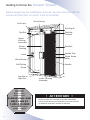
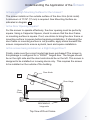
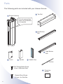
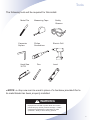
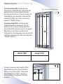
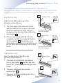
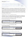
!
Installation Manual for
Installation
Questions?
Missing Parts?
Replacements?
PLEASE CALL OUR
HELP LINE AT
1-866-333-8868
Please do not return
product to store
For Right Hinged Doors
Please read entire manual
before beginning installation.
Recommended for In-Swing Doors
(Not for use on sliding patio doors)
Durable. Reliable. Attractive.
For door openings up to 36” (914 mm) wide
and 81 3/16” (2,062 mm) high
Quick and
Easy to Size
and Install
QC03-0903R
Congratulations and
thank you for purchasing an
Unseen Screen!
The Unseen retractable screen is designed and manufactured by Seiki
Screen Systems, one of the world's largest manufacturers of retractable
screens. Phantom Screens, North America's leading brand of retractable
solutions, is proud to bring you these innovative products. Thanks to
engineered design and rigorous product testing, this screen will provide
years of dependable operation. Plus, it comes with a factory supplied limited
lifetime warranty against manufacturer’s defects on all parts, except mesh.
The screen was designed for easy sizing and installation. This Installation
Manual provides a step by step guide through the entire process.
Any questions? Contact our Toll Free Help Line at
1-866-333-8868.
2
Index
Getting to Know the Unseen Screen................. 4
Understanding the Application of the Screen.... 5
Parts and Tools............................................. 6, 7
Measuring the Door Opening............................ 8
Choosing the Correct Bottom Rail..................... 9
Sizing the Screen............................................ 10
Cutting the Top and Bottom Rails.................... 11
Cutting the Screen Housing.................12, 13, 14
Installing the Top Rail...................................... 15
Installing the Screen Housing.......................... 16
Installing the Bottom Rail............................ 17, 18
Final Steps................................................ 19, 20
Notes Page...................................................... 21
Service and Maintenance, Warranty......... 22, 23
3
Getting to Know the Unseen Screen
Before beginning the installation process, become familiar with the
screen and the door on which it will be installed.
Wood Screw
End Cap L
End Cap R
Top Rail
Side Bar
Cushion
Upper
Housing
Assembly
Screen
Housing
Side Bar
Handle Grip
Latch
Wood Screw
Mesh
Wood Screw
Handle
Self Drilling
Screw
Low Rail or
High Rail
!
Installation
Questions?
Missing Parts?
Replacements?
PLEASE CALL OUR
HELP LINE AT
1-866-333-8868
Please do not return
product to store
4
Lower Housing
Assembly
! ATTENTION !
Insect screens are intended to provide reasonable
insect control and are not intended to provide security
or retention of objects, animals or persons.
Understanding the Application of the Screen
Is there enough Mounting Surface for the Unseen?
The screen installs on the outside surface of the door trim (brick mold). A minumum of 11/16" (17 mm) is required. See Mounting Surface as
indicated in diagram A .
Is the Door Opening Square?
For the screen to operate effectively, the door opening must be perfectly
square. Using a Carpenter Square, check to ensure that the door frame
or mounting surface is square. If not, use shims to bring the door frame or
mounting surface to square before beginning installation. If shimming the
door frame or mounting surface is not possible, apply shims beneath the
screen components to ensure a plumb, level and square installation.
Is this screen being installed on a Right Hinged Door?
Finally, make sure the correct model has been purchased! The screen in
this package is configured for a “RIGHT” hinged door. The hinges should
be on the right side and the door knob should be on the left. This screen is
designed to be installed on in-swing doors only. This requires the screen
to be installed on the outside of the building.
Door Knob
A
Doo
r
Door Hinge
Door
Frame
INSTALL ON
BRICKMOLD,
hinge side
Top View of Door Frame
5
Parts
The following parts are included with your Unseen Screen.
2 Top Rail
1 S
creen Housing
Do not remove blue
tape until installation
is complete
3 Low Bottom Rail
4 High Bottom
Rail
5
Latch
6 Handle
7
Handle Grip
Drill bit
Self Drilling Metal Screw (4 pcs.) Stainless Steel
8
Painted Wood Screw (11 pcs.) for Side Bar
6
Protective
Sticker
Tools
Hack Saw 32 TPI
Measuring
The following
tools will be required
forTape
this install.
Hack Saw 32 TPI
Measuring Tape
Hack Saw 32 TPI
Measuring Tape
Hack Saw Metal
32 TPIFile
Metal
Hack Saw
32 File
TPI
Level
Safety
Glasses
Measuring Tape
Measuring
Tape
Measuring Tape
Carpenter Square
Philips Screwdriver
Electric Drill
Carpenter
Philips
Electric Drill
Carpenter Square
Philips Screwdriver
Screwdriver
Electric Drill
SquareSquare
Carpenter
Philips
Screwdriver Electric Electric
Drill
Carpenter Square
Philips
Screwdriver
Drill
Carpenter Square
Hack Saw
Metal File
32 Saw
TPI 32 TPI
Hack
Metal
File
Metal File
Metal File
Philips Screwdriver
Pen
Electric Drill
Level
Level
Measuring TapeLevel
Level
Level
Level
Metal File
saw can be used in place of a hacksaw provided that a
* NOTE: a chop
Carpenter Square
Philips Screwdriver
Electric Drill
bi-metal blade has been properly installed.
! WARNING
Improper use of hand or power tools can result in
personal injury and/or product damage. Follow
equipment manufacturer’s instructions for safe
operation. Always wear safety glasses.
Metal File
Level
7
Measuring the Door Opening
For the width (W), measure the
dimension between the right and left
exterior trim or door frame at both
the top and bottom of the doorway as
indicated in the diagram. Record the
smallest of the two sizes in the box
labeled "Width" below.
Top Trim Mounting Surface
T
For the height (H), measure the inside dimension between the top
exterior trim or door frame and the
door sill at the lowest point in its slope.
Measure in all three locations as
indicated in the diagram and record the
smallest dimension in the box labeled
"Height" below.
Width (W)
Finally, measure the height of the
lowest flat portion of the exterior
trim or door frame (T). This must
be a minimum of 5/8" (16 mm),
and must be completely flat and
square.
8
Height (H)
T
Choosing the Correct Bottom Rail
The screen package comes with two Bottom Rail options to
accommodate different configurations. Choosing the correct Bottom Rail
is important, since this will determine the final cut size of the Screen.
B
Low Bottom Rail
Use the Low Bottom Rail
following circumstances:
3
in the Door Sill
1. The front edge of the door sill is flush
with the exterior trim or door frame and
there is a minimum of 9/16" (15 mm)
clearance from the top of the sill and the
deck below B .
2. There is a minimum of 9/16" (15 mm)
clearance, but the front edge of the door
sill is recessed C . Use a shim or an
aftermarket sill extension to extend the sill
so it is flush with the exterior trim or door
frame.
High Bottom Rail
Use the High Bottom Rail
following circumstances:
Exterior Trim
4
Exterior Trim
Door Sill
The height of the door sill
(min 9/16" (15 mm))
Exterior Trim
1. The door sill is flush with the exterior
trim or door frame B , but there is less
than 9/16" (15 mm) clearance to the deck
below.
3. The door sill has an existing track for a
sliding screen E .
C
D
in the
2. The door sill extends beyond the
exterior trim D .
The height of the door sill
(min 9/16" (15 mm))
Door Sill
E
Rail for flat panel
Screen
9
Sizing the Screen
If the door opening is smaller than 36" (914 mm) wide and 80 9/16" (2,047 mm) high when using the Low Bottom Rail 3 or less than 81 3/16" (2,062 mm) high when using the High Bottom Rail 4 , the
Screen must be cut.
NOTE: Actual Unseen components are designed with offset dimensions
to fit a standard opening (see dimensions above); therefore parts will not
measure the same as the doorway dimensions. To fit a smaller opening,
determine the Length to be Cut from the components by calculating the
difference between your doorway measurements and the standard width
and height provided above.
Determining Cut Size for Screen Housing
Important: The cut size of the Screen Housing depends on whether the
Low Bottom Rail 3 or High Bottom Rail 4 is selected. Ensure that the
correct formula is used (see page 9 for Bottom Rail selection).
For Screen Housing with Low Bottom Rail
Use the following formula:
(Measured Height)
80
9
/16” (2,047 mm) - [
[Length to be cut off]
]=
For Screen Housing with High Bottom Rail
Use the following formula:
(Measured Height)
81
3
/16” (2,062 mm) - [
[Length to be cut off]
]=
Determining Cut Size for Top Rail and Bottom Rail
Use the following formula:
(Measured Width)
36” (914 mm)
10
-[
]=
[Length to be cut off]
Cutting the Top and Bottom Rails
NOTE: Top Rail
2
is clearly labeled with CUT and NO CUT zones.
2
DO NOT
cut this end.
Cut this end
Door opening
1. Remove the End Caps from both sides of the Top Rail
2
.
2. Using the "Length to be Cut" dimension for Top Rail 2 calculated on
Page 10, carefully measure and mark the rail on all sides to ensure an
even cut.
3. Cut straight through Top Rail
2
.
Cutting the Bottom Rail
NOTE: Low and High Bottom Rails
and NO CUT zones.
3
and
4
are clearly labeled with CUT
1. Select the Bottom Rail chosen on Page 9.
2. Using the same "Length to be Cut"
dimension for Top Rail 2 , carefully
measure and mark the Bottom Rail
on all sides to ensure an even cut.
3. Cut straight through Bottom Rail
3
or
3
Cut this portion
4
NOTE: After cutting any part of the screen,
use a file to remove any burrs from the
surfaces.
.
OR
4
Cut this portion
11
Cutting the Screen Housing
NOTE: All cutting will be done on the lower end of the Screen Housing,
away from the Upper Housing Assembly and spring mechanism.
The Screen is clearly labeled with CUT and NO CUT zones.
1. Begin by tightening the screw at the top of the Upper Housing
Assembly F . This will align the Mesh Cylinder for cutting.
2. Remove the Lower Housing Assembly and washer by removing the two
screws with a Philips screwdriver. G
Upper Housing Assembly
F
Lower Housing
Assembly
1
G
Washer
3. Slide the Side Bar Cushion off of the Side Bar and slide the Bottom
Rail Guide off of the Screen Housing 1 . H
H
Side Bar
Side Bar Cushion
Inner Handle
Bottom Rail Guide
12
Cutting the Screen Housing
4. Carefully measure and mark the Screen Housing on all sides using the
"Length to be Cut" dimension for Screen Housing 1 calculated on Page 10.
5. Cut straight through Screen Housing
1
and the fiberglass mesh. I
Do not remove blue
tape until installation
is complete.
I
1
Important
Cut only from bottom as
indicated by hack saw
illustration.
Cut this
portion
6. Replace the Side Bar Cushion onto the Side Bar, ensuring that it is
pushed in as far as it will go. J
J
Side Bar Cushion
Side Bar
K
Side Bar
Side Bar Cushion
Ensure that the SIDE
BAR CUSHION is
pushed completely in
place.
Side Bar
Side Bar
Cushion
1
Inner Handle
Bottom Rail Guide
Washer
Lower Housing Assembly
7. Slide the Bottom Rail Guide back onto Screen Housing 1 and reattach
the Lower Housing Assembly and Washer using the two screws. K
13
Cutting the Screen Housing
8. Loosen the screw at the top of the Upper Housing Assembly until the
head of the screw is slightly above the Top. L
L
9. Finally, remove the blue tape, slide the Inner Handle to the center of
the Screen Housing and tighten the screws. M
Center and tighten inner handle
M
Remove
the blue tape
14
Installing the Top Rail
The top edge of the Top Rail 2 will be mounted exactly 5/8" (16 mm) from
the bottom edge of the exterior top trim or door frame.
1. Make a mark 5/8" (16 mm) up from the bottom edge of the exterior trim
or door frame. Using a level, extend the mark across the surface. This
mark will be the reference point for the top edge of the Top Rail 2 .
2. Apply the Protective Sticker
right side.
8
to back edge of Top Rail
2
on the 3. Remove the backing on the adhesive strip and position Top Rail
along the guide line.
4. Secure Top Rail
2
2
using the Wood Screws provided.
Backing of Adhesive Strip
2
5/8"
(16 mm)
8 Protective
Sticker
Protective Sticker 8 must be
applied half way to the back
edge of 2 and then fold the
other half over after cutting
has been completed.
Mounting Surface
15
Installing the Screen Housing
1. Insert the rollers of the Screen Housing into Top Rail
2
(Right side).
2. Peel the backing off the adhesive strip along the back of the Side Bar.
3. Making sure the top of the Side Bar Cushion is level with the Upper
Housing Assembly, fasten the Side Bar Cushion to the exterior trim or
door frame using a Wood Screw.
4. Press the Side Bar firmly in place along the exterior trim or door frame,
making sure that the fiberglass mesh is kept flat, and the Side Bar is
square to Top Rail 2 .
5. Using the Wood Screws provided, secure the Side Bar to the exterior
trim or door frame.
Exter
ior Tr
2
im
Side Bar Cushion
must be positioned
level with the Upper
Housing Assembly.
Rollers
Upper Housing
Assembly
Side Bar
Cushion
Side Bar
Side Bar Cushion
must be positioned
flush and square
to 2 .
NOTE: If during the
sizing of Screen
Housing 1 , the
predrilled hole for
the Bottom Side Bar
Cushion was removed, a
new hole must be drilled.
16
Wood Screw
[for Side Bar]
Side Bar
Cushion
Installing the Bottom Rail
1. Select the Bottom Rail (Low or High) chosen on Page 9, and remove
the adhesive backing.
2. While slightly lifting the Bottom Rail Guide on the Screen Housing
insert Bottom Rail 3 or 4 .
1
,
3. Slide the Bottom Rail in just far enough so that when laying flat on sill,
it will be tight against the left side of the door frame.
Lift
1
Bottom Rail Guide
3 or 4
Insert
Do
or
ll
Si
Important
While lifting the Bottom Rail Guide slightly, insert
the Bottom Rail 3 / 4 into it. The installation
function is the same for either Bottom Rail type.
The backing of
the adhesive
strip
17
Installing the Bottom Rail
Positioning the Bottom Rail
A. Door Sill flush with Exterior Trim B. Door Sill recessed from Exterior Trim
Exterior Trim
Exterior Trim
Front edge
flush with
Exterior Trim.
3
Min. 9/16"
(15 mm)
Front edge
flush with
Door Sill.
Door Sill
Min. 9/16"
(15 mm)
Door Sill
3
Shim can be installed
between Door Sill and
3 for added support.
Shim not included.
C. Door Sill extends beyond
Exterior Trim
Exterior Trim
Front edge
flush with
Exterior Trim.
4
D. Door Sill with Existing
Screen Tracks
Exterior Trim
Front edge
flush with
Exterior Trim.
Door Sill or
Concrete Surface
4
Existing
Screen Tracks
Door Sill or
Concrete Surface
4. While keeping it tight to the left door frame, position the bottom rail
flush with the exterior trim (see above drawing), and then press down
firmly into place.
5. Through the predrilled holes
in the Bottom Rail 3 or 4 ,
fasten to the door sill using
the Self Drilling Metal
Screws provided. N It is not
necessary to pre-drill the
surface below.
18
N
Self Drilling
Metal Screws
Final Steps
Install the End Caps
1. Locate the two End Caps removed during earlier installation steps and
press firmly into place on both ends of Top Rail 2 O .
End Cap L
End Cap R
O
2
Center of Frame
4" (100 mm)
5
Push firmly in place
1
Install the Latch
1. Position Latch 5 to the left inner edge of the exterior trim or door
frame, 4" (100 mm) below the center of the frame. O
2. Fasten in place using the Wood Screws provided. P
Ex
ter
io
r Tr
im
5
P
Wood Screw
19
Final Steps
Installing the Handle
1. Remove the backing on the adhesive strip from the back side of the
Handle 6 .
2. Adhere the Handle
door opening.
6
onto the Screen Housing
1
at the center of the
3. Remove the backing on the adhesive strip from the Handle Grip
4. Insert the Handle Grip 7 into the hole on the Handle
onto the Screen Housing 1 .
6
7
.
and adhere
1
7
Center of
the opening
6
Congratulations! You have now installed your
Unseen Screen!
20
21
Service and Maintenance Hints
The Unseen Screen is designed and engineered to be maintenance
free. The following are some helpful hints to ensure the smooth
operation of your Unseen Screen for years to come.
• The moving components used in the screen contain nylon. This
combination of compounds is strong, impact resistant, and self-lubricating. Do not use oil, grease, petroleum or oil based sprays
or lubricants on any of the components on the screen. These products
attract dirt and debris, which may affect the operation of the Unseen
Screen. However, the periodic application of a dry silicone lubricant to
the moving parts is permissible.
• We recommend that when the screen is not required, keep it stored
away in the Screen Housing. This will extend the life of the mesh and
keep it clean.
• The Bottom Rail should be kept free of dirt and debris. Use a broom to
remove any obstructions from the Bottom Rail.
• If the screen mesh becomes damaged or torn, a Replacement Mesh
Cartridge can be purchased separately through the help line.
If you have any questions during the installation of the Unseen Screen,
please call toll free:
1-866-333-8868
22
Unseen Screen Limited Lifetime / Non-transferable
Manufacturer's Warranty
The Unseen Screen is warranted by Seiki Screen Systems to be free of manufacturer’s defects in materials or workmanship, for as long as the original purchaser owns and/or resides at that residence and that the product remains at
its original point of installation. Seiki Screen Systems will repair or replace at its discretion, any component, within the terms and conditions of this warranty, which is
deemed as being defective from the manufacturing process upon proof of purchase.
This warranty excludes the screen mesh.
Furthermore this warranty does not cover components damaged through improper
use or installation, or if components have been altered from their original state in a
manner not otherwise prescribed in this manual. This warranty is strictly limited to
defective components only. This non-transferable, limited warranty excludes labor,
breakage or damage due to normal wear and tear, lack of maintenance, or use for
other than residential applications, accidents and “acts of God”.
Replacements or repairs made subject to this limited warranty are otherwise warranted for the balance of the original warranty period. Seiki Screen Systems’ liability under this limited warranty is restricted to the corrective actions as set forth
herein and contrarily repudiates all incidental and consequential damage. It is the
responsibility of the consumer to notify Seiki Screen Systems of missing components,
within 30 days of the purchase of the Unseen Screen.
The Unseen Screen is designed to assist in keeping unwanted insects from the home;
it is in no way intended as a safety or security device to prevent access or exit by individuals, animals or small children. Liability for any damages, including but not
limited to general, special, indirect, incidental, consequential, aggravated, punitive or
exemplary damages, and economic loss, as well as for breach of any expressed or
implied warranties, including but not limited to implied warranties of merchantability,
quality and fitness for any purpose other than as prescribed herein, is disavowed and
omitted here from, to the extent that such a disclaimer and preclusions are permitted
by the laws of any particular jurisdiction.
Maintenance: Keep Bottom Rail clean and free of debris. Periodic use of silicone
spray on the rollers of the Upper Housing Assembly and the Bottom Rail Guide is recommended; do not use petroleum-based lubricants.
Unseen Screen
Designed and Manufactured by Seiki Screen Systems
Marketed by Phantom Screens
PRODUCT INFORMATION MANUAL
For warranty claims
Call 1-866-333-8868
23
Designed & Manufactured by Seiki Screen Systems ™
Marketed & Distributed by Phantom Screens ®
Seiki Screen Systems
Phantom Mfg. (Int'l) Ltd.
www.seikiscreensystems.com
www.phantomscreens.com
© 2009 Phantom Mfg. (Int'l) Ltd. & Seiki Screen Systems
24