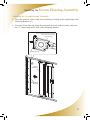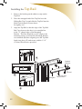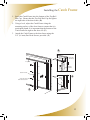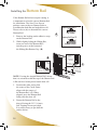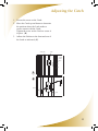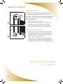
1
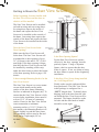
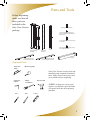
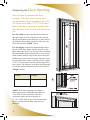
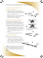
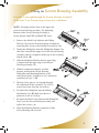
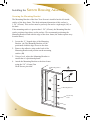
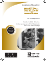
Installation Manual for
For Left Hinged Doors
Durable. Reliable. Attractive.
For door openings up to 36” (914 mm) wide
and 81 1/4” (2,064 mm) high
Quick and
Easy to Size
and Install
Congratulations and
thank you for purchasing
Sure View!
The Sure View retractable screen is designed and manufactured by Seiki
Screen Systems, the world’s largest manufacturer of retractable screens. Phantom Screens, North America’s leading brand of retractable solutions, is proud to bring you these innovative products. Thanks to
rigorous design and product testing, the Sure View Screen will provide
years of dependable operation. Plus, it comes with a factory-supplied
limited lifetime warranty on all parts against manufacturer’s defects.
The Sure View Screen is designed for easy sizing and installation. This
Installation Manual provides a step by step guide through the entire
process.
Any questions? Contact
our Help Line, Toll Free at
1-888-PHANTOM
(1-888-742-6866).
Index
Getting to Know the Sure View Screen ........................... 4
Parts and Tools ................................................................ 5
Measuring the Door Opening .......................................... 6
Sizing the Sure View Screen ........................................... 7
Cutting the Top/Bottom Rail and Catch Frame ............... 8
Cutting the Screen Housing Assembly ............................ 9
Installing the Screen Housing Assembly ................ 10 - 11
Installing the Top Rail .................................................... 12
Installing the Catch Frame .............................................
13
Installing the Bottom Rail .............................................. 14
Adjusting the Catch ....................................................... 15
Final Adjustments .......................................................... 16
Service and Maintenance Hints ..................................... 17
For installations on double doors (French doors) you
will need: one left Sure View Screen, one right Sure
View Screen, and one Double Door Kit. Please refer to Installation Manual within the “Double
Door Kit” prior to installation.
The Sure View Screen is not intended for installation on a Sliding Patio Door.
Getting to Know the Sure
View Screen
Before beginning, become familiar with
the Sure View Screen and the door on
which it will be installed.
Top Rail
Sliding Bar
Top Rail
End Cap
Mesh Lock
Adjuster
The Sure View Screen can be installed
on both in-swing and out-swing doors.
In-swing doors open to the inside of
the home and require the Sure View
Screen to be installed on the outside of
the home. Out-swing doors open to the
outside of the home and require the Sure
View Screen to be installed on the inside
of the home.
Does the Sure View Screen fit the
Door Opening?
Sliding Bar
Top Cap
Screen
Housing
Catch
Catch
Frame
One Touch
Latch
Bottom Rail
Type A or B
Spring Tension
Adjuster
Make sure the Sure View Screen will
fit the door. The Sure View Screen will
accommodate a door opening of up to
36” (914 mm) wide and 81 1/4” (2,064
mm) high. If the door opening is larger
than this, the Sure View Screen can still
be installed by attaching a filler strip
under the door frame to reduce the height
of the door opening. Refer to page 6 for
details.
Retracting
Mesh Guide
Sliding Bar
Bottom Cap
Is the Door Opening Square?
For the Sure View Screen to operate
effectively, the door opening must be
perfectly square. Using a Carpenter
Square, check to ensure that the door
frame is square. If not, use shims to bring
the door frame to square before beginning
installation.
Is there enough Mounting Surface for the
Sure View Screen?
Is this Sure View Screen being installed
on a Left Hinged Door?
The Sure View Screen is a recess mount
screen which installs on the inside
surface of the door frame (Mounting
Surface as indicated in diagram (A)). To
ensure that the Sure View Screen is fully
recessed after installation, there must be
at least 1 5/8” (42 mm) of mounting
surface. However the Sure View Screen
can accommodate a minimum mounting surface of 1 1/8” (28 mm). In
this instance, the Mounting Bracket will extend slightly beyond the door frame.
This mounting surface must be flat and
flush, and at a right angle (90º) to the door.
Finally, make sure the right model has
been purchased! The Sure View Screen
in this package is configured for a
“LEFT” hinged door. To identify door
hinging, look at the door from the side
on which the Sure View Screen will be
mounted. The hinges should be on the
left side and the door knob or handle
should be on the right.
4
A
Mounting Surface
Parts and Tools
Before beginning,
make sure that all
these parts are
included in the
Sure View Screen
package.
Stickers, 2pcs. for Latch
5/8” (16 mm) Pan Head Screws,
10pcs. for Mounting Bracket and
Catch Frame
1-1/4” (32 mm) Wood Screws, 3pcs.
for Top Rail
Screen Housing
Assembly
Bottom Rail Type “A”
(used on flat door sills)
Mounting
Bracket
Catch
Frame
Bottom Rail Type “B”
(used on angled door sills)
5/8” (16 mm) Self Tapping Screws,
2pcs. for Bottom Rail
Top Rail
Required Tools
Hacksaw *
32tpi
Measuring tape
Sure View Screens can be sized and
installed using common household
tools. Make sure all necessary tools
are available before beginning.
Carpenter
square
Philips
screwdriver
Electric drill
*NOTE: A chop saw can be used
in place of a hacksaw provided that
a bi-metal blade has been properly
installed.
File
Pen
Level
5
Measuring the Door
Opening
Now it's time to measure the door
opening. The Sure View Screen will
accommodate a door opening of up to 36”
(914 mm) wide and 81 1/4” (2,064 mm)
high. If the door opening is smaller than
this, the Sure View Screen will have to be
cut.
W
H
For the width, measure the dimension between
the right and left sides of the door frame at both
the top and bottom of the doorway as indicated in
the diagram. Record the smallest of the two sizes
in the box labeled “Width” below.
For the height, measure the dimension between
the top of the door frame and the door sill at the
point where the Sure View Screen will be installed.
We recommend positioning the Sure View Screen
flush with the outside edge of the door frame (the
furthest point away from the door). Measure from
the top of the door frame to the door sill at a point
1 5/8” (42 mm) back from the outside edge of the
door frame. (A) Measure in all three locations and
record the smallest dimension in the box labeled
“Height” below.
Width
Height
AAA
NOTE: If the door opening is too high, a
filler strip must be installed before the Sure
View Screen can be installed. The filler
strip must reduce the door opening to 81 1/4" (2,064 mm) or less. All measurements
must be made after the filler strip has been
installed.
6
Sizing the Sure
View Screen
If the door opening is smaller than 36” (914 mm) wide and 81 1/4” (2,064 mm) high, the Sure View Screen must be cut.
Determine Length to be Cut
from Top and Bottom Rails
To determine the length to be cut from the Top and Bottom Rails,
use the following formula:
(Measured Width) [Length to be cut off]
( 36” (914 mm) - [
]) =
Determine Length to be Cut from
Screen Housing Assembly and Catch Frame
To determine the length to be cut from the Screen Housing Assembly and Catch Frame, use the following formula:
(Measured Height)
( 81 1/4” (2,064 mm) - [
[Length to be cut off]
]) =
H
W
7
Cutting the Top and Bottom Rail and Catch Frame
Cutting the Top Rail of the Sure View
Screen is an easy process.
1.
Using the “Length to be cut” dimension
calculated on Page 7, carefully measure the Top Rail on the end opposite the end cap. Mark on all sides to ensure an even cut.
A
2. Wearing safety glasses, cut straight through the Top Rail using either a chop saw or a hacksaw with a bi-metal blade. (A)
Choosing and Cutting the Bottom Rail
Before cutting, it is important to select the correct Bottom Rail for installation. The Sure View
Screen package comes with two Bottom Rails to
accommodate both flat and angled door sills. Please
refer to (B) to determine the correct Bottom Rail.
1. Using the same “Length to be cut” dimension used for the Top Rail, measure and mark the appropriate Bottom Rail on all sides to ensure an even cut. The Bottom Rail can be cut on either side.
B
Choose the correct Bottom Rail for either
flat or angled door sills.
C
2. Cut straight through the Bottom Rail. (C)
Cutting the Catch Frame
Either end of the Catch Frame can be cut.
1. Using the Screen Housing and Catch Frame “Length to be Cut” dimension calculated on
Page 7, carefully measure and mark the Catch Frame on all sides to ensure an even cut.
2. Cut straight through the Catch Frame. (D)
Catch Frame
NOTE: It is important to wear safety glasses at all
times when cutting components of the Sure View
Screen. After cutting any part of the Sure View
Screen use a file to remove any burrs from the cut
surfaces.
8
D
Length
to be cut
gth
e cut
Cutting the Screen Housing Assembly
It is easy to cut right through the Screen Housing Assembly
of the Sure View Screen using a chop saw or hacksaw.
NOTE: All cutting will be done on the upper end
of the Screen Housing Assembly. The Mounting
Bracket on the Screen Housing Assembly is
clearly labeled with CUT and NO CUT zones.
A
1. Remove the Mesh Lock Adjuster and Sliding
Bar Top Cap from the Screen Housing Assembly by
removing their screws with a Phillips screwdriver. (A)
2. Detach the Sliding Bar from the Sliding Bar Bottom Cap,
and slide it towards the upper end of the Screen Housing
Assembly until it is aligned with the top of the Assembly
and the mesh. (B)
3. Slide the Mounting Bracket until its upper edge
is aligned with the upper edge of the Screen
Housing Assembly. (C)
4. With all components aligned, carefully
measure and mark the Screen Housing,
Sliding Bar and Mounting Bracket on all
sides based on the “Length to be cut” dimension
calculated on Page 7. (D)
C
B
5. Wearing safety glasses, cut straight through
all components of the assembly. Use a file to
remove any burrs from the cut surfaces.
6. Re-attach the Sliding Bar onto the Sliding
Bar Bottom Cap. (B) Make sure that it is
pushed in as far as it will go.
D
7. Re-attach the Mesh Lock Adjuster and Sliding Bar
Top Cap to the Screen Housing Assembly and
replace the screws. (A)
8. Slide the Mounting Bracket completely off the
Screen Housing and set aside.
9
Installing the Screen
Housing Assembly
Securing the Mounting Bracket
The Mounting Bracket of the Sure View Screen is installed on the left inside
surface of the door frame. The ideal minimum dimension of this surface is 1 5/8” (42 mm). This surface must be perfectly flat and at a right angle (90º) to
the door.
If the mounting surface is greater than 1 5/8” (42 mm), the Mounting Bracket
can be positioned anywhere on this surface. We recommend positioning the
Mounting Bracket flush with the edge of the door frame (the furthest point away
from the door.)
1. Locate the “L” shaped edge of the Mounting Bracket. (A) The Mounting Bracket will be positioned with this edge closest to the door.
2. Remove the adhesive strip on the back of the
Mounting Bracket and position on the mounting
surface. (B)
3. Using a level, adjust the Mounting Bracket to ensure that it is positioned plumb.
4. Attach the Mounting Bracket to the door frame using the 5/8” (16 mm) Pan Head Screws provided.
Mounting Surface
A
“L” Shaped Edge
B
Mounting Bracket
5/8” (16 mm)
Screw
10
Installing the Screen
Housing Assembly
Attaching the Screen Housing Assembly
1. Place the front left corner of the Screen Housing Assembly in the outside edge of the Mounting Bracket. (C)
2. Pivot the Screen Housing along this point until the back of the Assembly snaps into the “L” shaped edge on the back of the Mounting Bracket.
Snap Screen Housing into “L” Shaped
Edge of Mounting Bracket
Screen Housing
Mounting Bracket
C
Screen
Housing
Mounting
Bracket
11
Installing the Top
Rail
1. Remove the backing on the adhesive strip on the Top Rail.
2. Place the uncapped end of the Top Rail over the Sliding Bar Top Cap and slide the Top Rail into the Mesh Lock Adjuster. Ensure that it fits tightly. (A)
3. Align the Top Rail so that the edge of the Top Rail End Cap closest to the door is in a straight line to the “L” shaped edge of the Mounting Bracket. This line should be at a 90º angle to the mounting surface on which the Mounting Bracket was attached. (B) Once aligned, press the Top Rail firmly into place (C) and secure with the 1 1/4”
(32 mm) Wood Screws provided.
Mesh Lock
Adjuster
Top Rail
A
Sliding Bar Top Cap
Mounting Bracket
Top Rail
End Cap
Top Rail End Cap
Align
Top Rail
B
Push
Sliding Bar
C
12
1 1/4” (32 mm)
Wood Screw
Installing the Catch
Frame
1. Insert the Catch Frame into the bottom of the Top Rail End Cap. Ensure that the Top Rail End Cap fits tight to the right side of the door frame. (D)
2. Using a level, adjust the Catch Frame along the mounting surface of the door frame to ensure that it is positioned plumb. It is important that the bottom of the Catch Frame fits tight to the door sill. (E)
3. Attach the Catch Frame to the door frame using the 5/8”(16 mm) Pan Head Screws provided. (F)
D
Push
Top Rail
End Cap
Insert
Top Rail
Catch
Frame
Catch Frame
Catch
Frame
5/8” (16 mm)
Pan Head Screw
E
Push
F
13
Installing the Bottom
Rail
If the Bottom Rail did not require cutting, it
is important to select the correct Bottom Rail
for installation. The Sure View Screen package comes with two Bottom Rails to
accommodate both flat and angled door sill.
Please refer to (A) to determine the correct
Bottom Rail.
1. Remove the backing on the adhesive strip on the Bottom Rail.
2. Bottom Rail Type“A”
A
While slightly lifting the Sliding Bar,
insert one end of the Bottom Rail
into the groove at the bottom of
the Sliding Bar Bottom Cap. (B)
B
Sliding
Bar
Screen Housing
Bottom Rail
NOTE: If using the Angled Bottom Rail, ensure that it is oriented so that the top of the Bottom Rail is flat and level when placed on the door sill.
3. Position the other end so that the center of the Catch Frame aligns with the center of the Bottom Rail. (C) When aligned, press the Bottom Rail firmly onto the door sill.
4. Fasten the Bottom Rail to the door sill using the 5/8” (16 mm) Self-Tapping Screws provided. It is not necessary to pre-drill the surface below.
14
Flat Surface
Bottom Rail Type“B”
Angled Surface
Catch
Frame
Align The
Centre
Bottom
Rail
C
5/8” (16 mm)
Self Tapping
Screw
Bottom
Rail
Adjusting the Catch
1. Loosen the screw on the Catch.
2. Move the Catch up and down to determine the position where the Latch makes a secure contact with the Catch. Tighten the screw on the Catch to secure it in place. (D)
3. Adhere the Stickers to the front and rear of the Latch as indicated. (E)
Sliding Bar
Latch
Catch
Frame
Catch
D
E
Sticker
Sticker
Latch
15
Final Adjustments
Adjusting the Mesh
Mesh Lock Adjuster
Dial
Lock
A
Spring
Tension
Adjuster
Dial
B
Increase Spring Tension
The Sure View Screen can be adjusted to reduce
the amount of mesh discharged from the Screen
Housing. This keeps the mesh tight to maintain the
effectiveness of the Sure View Screen in keeping
out unwanted insects.
1. 2. Close the Sure View Screen.
Turn the dial on the Mesh Lock Adjuster as
indicated in illustration (A) until meeting with resistance, but without over-tightening.
Adjusting Spring Tension
1. 2. If the Sure View Screen does not retract fully or quickly enough, turn the dial on the Spring Tension Adjuster, as indicated in illustration (B), to increase spring tension.
If the Sure View Screen retracts too quickly, turn the dial on the Spring Tension Adjuster in the opposite direction to reduce spring tension.
The Sure View Screen Installation
is Now Complete!
16
Service and Maintenance Hints
The Sure View Screen is designed and engineered
to be maintenance free. Please review these helpful
hints to ensure the smooth operation of the Sure View Screen for years to come:
•
All moving components used in the Sure View Screen are manufactured from a mixture of nylon and other materials. This combination of compounds is strong, impact resistant, and self-lubricating. Do not use oil, grease, or oil based sprays or lubricants on any of the components on the Sure View Screen. These products attract dirt and debris, and may cause the Sure View Screen to react abnormally.
However, the periodic application of a dry silicon lubricant to the moving parts is permissible.
•
We recommend that while not in use, the Sure View Screen be kept in the retracted position. This will help extend the life of the screen mesh. In the retracted position, the mesh is protected and kept clean.
• The Bottom Rail should be kept free of dirt and debris. Use a broom to remove any obstructions from the Bottom Rail.
• If the screen mesh becomes damaged or torn, a
Replacement Mesh Cartridge can be purchased
separately through your local dealer or retailer.
* Before installing the Sure View Screen, please
take the time to read the installation instructions
thoroughly.
17
Help Hotline
The Sure View Screen was designed for easy sizing and
installation. This Installation Manual provides a step by step
guide through the entire process.
If there are any questions during the installation of the Sure View Screen, please call toll free:
1-888-PHANTOM
(1-888-742-6866)
18
Sure View Screen
Limited Lifetime/Non-transferable
Manufacturer’s Warranty
The Sure View Screen is warranted by Seiki Screen Systems to be free of manufacturer’s
defects in materials or workmanship, for as long as the original purchaser owns and or
resides at that residence and that the product remains at its original point of installation.
Seiki Screen Systems will repair or replace at its discretion any component, within the
terms and conditions of this warranty, which is deemed as being defective from the
manufacturing process upon proof of purchase. This warranty excludes the fiberglass
screen mesh. Furthermore this warranty does not cover components damaged through
improper use or installation, or if components have been altered from their original state
in a manner not otherwise prescribed in this manual. This warranty is strictly limited to
defective components only. This non-transferable, limited warranty excludes labor,
breakage or damage due to normal wear and tear, lack of maintenance, or use for other
than residential applications, accidents and “acts of god”. Replacements or repairs made
subject to this limited warranty are otherwise warranted for the balance of the original
warranty period. Seiki Screen Systems’ liability under this limited warranty is restricted to
the corrective actions as set forth herein and contrarily repudiates all incidental and
consequential damage. It is the responsibility of the consumer to notify Seiki Screen
Systems of missing components, within 30 days of the purchase of the Sure View Screen.
The Sure View Screen is designed to assist in keeping unwanted insects from the
home; it is in no way intended as a safety or security device to prevent access by
individuals, animals or small children. Liability for any damages, including but not
limited to general, special, indirect, incidental, consequential, aggravated, punitive or
exemplary damages, and economic loss, as well as for breach of any expressed or
implied warranties, including but not limited to implied warranties of merchantability,
quality and fitness for any purpose other than as prescribed herein, is disavowed and
omitted here from, to the extent that such a disclaimer and preclusions are permitted
by the laws of any particular jurisdiction.
Maintenance: Keep Bottom Rail clean and free of debris. Periodic use of silicone spray
onto the inside of the Top Rail, the Bottom Rail and the Retracting Mesh Guide is
recommended; do not use petroleum-based lubricants.
Sure View Screen
Designed and Manufactured by
Seiki Screen Systems
PRODUCT INFORMATION MANUAL
For warranty claims
Call 1-877-446-7180
Or email: [email protected]
19
Designed & Manufactured by Seiki Screen Systems ™
Marketed and Distributed by Phantom Screens ®
Seiki Screen Systems
Call 1-877-446-7180
Or email: [email protected]
Phantom Mfg. (Int’l) Ltd.
Call 1-888-PHANTOM
Or email: [email protected]
www.seikiscreensystems.com
www.phantomscreens.com
© 2008 Phantom Mfg. (Int’l) Ltd. & Seiki Screen Systems
SU0508L