1
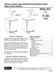
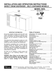
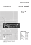
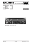
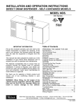
INSTALLATION and OPERATION INSTRUCTIONS
Dual Zone back bar cabinet — self contained
MODEL NOS.
BSDZ Series
BSDZ60
IMPORTANT INFORMATION
To register your product, visit our web site at
(www.perlick.com). Click on “Commercial”, then
“Service”. You will see the link to “Warranty
Registration Form”. You must complete and submit
this form or the installation date will revert back to
the ship Date.
This manual has been prepared to assist you in the
installation of your Cabinet and to acquaint you
with its operation and maintenance.
We dedicate considerable time to ensure that our
products provide the highest level of customer
satisfaction. If service is required, your dealer can
provide you with a list of qualified service agents.
For your own protection, never return merchandise
for credit without our approval.
We thank you for selecting a Perlick product and
assure you of our continuing interest in your
satisfaction.
Table of Contents
Preparing the Cabinet
Specifications.........................................................2
Tools Required.......................................................3
Plumbing................................................................3
Electrical.................................................................3
Uncrating and Inspection.......................................3
Installing Casters or Legs .....................................3
Placing the Cabinet................................................3
Leveling the Cabinet..............................................3
Installing the Base Plate.........................................3
Refrigeration and Temperature Control..................4
Cleaning the Cabinet..............................................4
Cleaning the Condenser........................................4
Cleaning Stainless Steel.........................................4
Replacement Parts.................................................5
Reversing Door Hinge............................................6
Wiring Diagram.......................................................7
WARNING: When lifting, the full weight of the
cabinet must be supported. Lift from the cabinet
base and not from the top. Improper lifting can
result in severe damage to the cabinet.
8300 West Good Hope Road • Milwaukee, WI 53223 • Phone 414-353-7060 • Fax 414-353-7069
Toll Free 800-558-5592 • E-Mail: [email protected] • www.Perlick.com
Form No. Z2304
Rev. 05.22.10
Installation and Operating Instructions
Sizes and Specifications, Dual Zone Back Bar Cabinets – Self Contained
Model Nos.
BSDZ60
2
Number oF doors
Cabinet
Dimensions
Length - Inches (mm)
60” (1524)
Depth - Inches (mm)
243/4” (629)
Height - Inches (mm)
341/2” (876)
15
CASE CAPACITY (based on 12 oz. Long Neck bottle)
CASE CAPACITY (based on use of full extension wine
48 bottles (per door)
shelves)
CONDENSING UNIT H.P.
1/4
RUNNING LOAD –AMPS
5.5
Ship Wt. Lbs. (kg.)
390 (177)
Interior
Door sill: High strength polyethylene. Door pan and ceiling: High strength polystyrene. Floor pan and Walls: Stainless steel. Includes pilasters, (2) vinyl coated shelves and floor rack per door, and interior lights.
Exterior
Front, back, top and sides stainless steel. Bottom galvanized steel. See optional accessories for door &
grille finishes.
Door Hinging
Stainless steel hinges with standard location as illustrated.For special hinging hinge locations starting left to
right. Field reversible.
Door Hardware
REFRIGERATION
ELECTRICAL
Door handles: Choice of full length stainless steel, classic 6” black vinyl wrapped pull or top mounted stainless steel pull tab. Lock finish: chrome.
R-134a capillary tube-type. Aluminum fin and copper tube evaporator, epoxy coated coil. Adjustable
temperature control for each temperature zone. Self-defrosting. Pull out condensing unit for service and
cleaning. Condensing unit and evaporator left side only.
115V, 60Hz., 1 phase AC. Furnished with 3-prong, 6 foot NEMA5-15 PC cord. Contact Perlick for other voltage/frequency requirements.
Evaporator condensate is removed automatically. Optional floor drain with 3/4” NPT at right end or 1” NPS out bottom come plugged from factory.
PLUMBING
INSULATION
Optional
Accessories &
Modifications
Foamed-in-place polyurethane, 2” walls, 11/2” top.
Door finishes
• Leg set
• Laminated top
Black vinyl coated
• Laminated ends
Stainless steel
• Full extension wine shelves
Customer choice of laminate
• Brass hardware
Painted in color of choice
(classic & full length only)
Prepared for field lamination
• Caster sets
Glass door with black vinyl • Base plates
coated frame
NOTE: This equipment is intended for the storage and display
of non-potentially-hazardous
bottled or canned products only.
12”
[305]
44” [1118] 2 DOOR
“NOTE B”
4 1/4”
[107]
6 5/16”
[161]
18 3/4” [476]
BACK LINER
TO INSIDE OF
DOOR SILL
16 3/8”
20”
“NOTE C”
24 3/4”
[629]
60” [1524] 2 DOOR
23 1/2”
[597]
DOOR
20”
31 1/4”
[794]
DOOR
HEIGHT
4 1/4”
[108]
7 3/16”
[182]
27 7/16”
[697]
DOOR
OPENING
19 7/8”
[505]
DOOR
OPENING
R23 1/2”
Glass door with stainless
steel frame
Glass door with laminated frame
Grille finishes
Black vinyl coated
Stainless steel
Customer choice of laminate
Painted in color of choice
34 1/2”
[876]
1 1/8”
[29]
4 3/16”
[106]
NOTE A: 3/4” NPT DRAIN EXIT
NOTE B: 1” NPS DRAIN EXIT
NOTE C: CONDENSING UNIT
AVAILABLE LEFT ONLY
22 3/4”
[578]
“NOTE A”
Perlick is committed to continuous improvement. Therefore, we reserve the right to change specifications without prior notice.
Form No. Z2304
Rev. 05.22.10
2
Preparing the Cabinet for Use
Suggested Tools
■
■
■
■
■
Installing Base Plate
2 Phillips Screwdriver.
#
10” Crescent Wrench.
9/ 16” Allen Wrench.
5/ 16” and 3/ 8” Hex Socket.
Power Drill or Driver.
Attach brackets to cabinet bottom in holes provided. Attach base plate to brackets. (See separate
instructions, provided with kit). When returning
cabinet to upright position, be careful not to bend
brackets.
Plumbing
WARNING!
For your convenience, a factory installed floor drain
is located in the back right corner of the cabinet. This
can be plumbed to an external floor drain. The floor
drain can be plumbed from the cabinet right side
using a 3⁄4” NPT connection or out the bottom using
a 1” NPS connection. Both ports of the drain come
capped from the factory.
Placing the Cabinet
To avoid compressor damage, after returning
cabinet to an upright position, let unit stand for
24 hours before plugging it in.
No plumbing required. Condensate from the cooling
coil is automatically evaporated through a condensate
pan located in the side condensing unit compartment.
Push the cabinet into place using rollers when
necessary. Important: Proper air flow around the
condensing unit is necessary for efficient operation.
Never obstruct the air flow in and out of the
condensing unit.
For sanitation purposes, it may be necessary to
seal the base of the cabinet to the floor. This can be
accomplished by laying a bead of silicone sealant
between the base of the cabinet and the floor as
shown by the figure at below.
Electrical
The cabinet must be connected to a separately
fused power source (see electrical specification
plate) and grounded in accordance with National
and Local Electrical Codes. Caution: Do not
attempt to operate the equipment on any other
power source than that listed on the Electrical
Specification plate.
CABINET
BEAD SILICON
SEALER (RTV)
Uncrating
and Inspection
Remove all crating material before operating.
Carefully inspect cabinet for hidden damage. If
damage is discovered, file your claim immediately
with the transportation company. Perlick is
not responsible for damage in transit.
Installing
Casters or Legs
(Optional)
FLOOR
Leveling the Cabinet
When the cabinet is in place, check installation with
carpenter’s level. When level front to back and left
to right, accumulated water will drain out of cabinet
evaporator drain.
(Optional)
Attach four casters or legs to the cabinet bottom;
mount rigid casters at the rear and swivel casters on
the front. Use the supplied 1/ 4”- 20 x 3/ 4” hex head
self-tapping machine screws.
Perlick is committed to continuous improvement. Therefore, we reserve the right to change specifications without prior notice.
3
Form No. Z2304
Rev. 05.22.10
General Information
Refrigeration and Temperature Control
NOTE:
Cabinet Temperatures lower than 34° will not allow
for proper defrosting of the evaporator coil. If
defrosting is necessary, remove product from the
cabinet and turn the control adjusting screw to the
OFF position until coil is defrosted.
Each zone has been factory set to maintain the
desired temperature specified when ordered. The
factory set storage temperatures are as follows:
Refrigerator — 34° to 38° F
White wine — 50° to 55° F
Red wine — 60° to 65° F
Cleaning the Cabinet
Adjusting the Temperature
Use a mild detergent and water to clean the inside
and outside of the cabinet. Dry thoroughly. Never
use a scouring pad or abrasive cleanser.
Note: An industrial strength, commercial cleaner
can be used to clean the outside of painted
cabinets.
The temperature control in the left compartment is
located on the left side of the evaporator fan panel.
The temperature control in the right compartment is
located on the top rear partition wall. You will need
a flat head screwdriver to turn the adjusting screw
on the control. Make small adjustments until the
desired temperature is achieved.
Cleaning the Condenser
The condenser (located behind the front grille
cover) should be inspected every 30 days and
cleaned, if necessary.
Colder Temperatures:
Turn the adjusting screw clockwise (to the right).
■ Warmer Temperatures:
Turn the adjusting screw counterclockwise
(to the left).
■ Temperature Control “OFF”:
Turn the adjusting screw completely counter-
clockwise to the “O” position until a click is noted.
The condenser fan motor turns off and on with
the compressor. The evaporator fan motor runs
continuously. The partition wall fan cycles with
the damper assembly.
■
Use a long handled, stiff brush to clean the dirt
from the front surface of the condenser. Keeping
the condenser free from dust and dirt will ensure
efficient operation.
Failure to keep the condenser clean will cause a
loss in condensing unit efficiency, and may damage
the compressor.
Caution: Do not bend the fins while brushing the
front of the condenser.
Recommended Cleaning Agents
Job Cleaning Agent* Comments
Routine Cleaning Soap, ammonia, detergent Apply with sponge or cloth.
Can be used on all finishes.
Fingerprints and smears Areal 20, Lac-O-Nu, Lumin Wash, Provides barrier film to minimize
O’Cedar Cream Polish fingerprints. Can be used on all finishes.
Stubborn stains and Allchem Concentrated Cleaner, Rub lightly, using dry or damp
Discolorations Samae, Twinkle, Zud Restoro, cloth in the direction of polish
Grade F or FFF Italian Pumice,
lines on the stainless steel.
Whiting or Talc, Liquid Nu Steel,
Copper’s or Revere Stainless Steel
Cleaner, Lumin Cleaner, Sta-Clean,
Cameo Copper Cleaner, Allen Polish
Highlite, Penny-Brite, Copper Brite
*Use of propriety names is intended only to indicate a type of cleaner and does not constitute an endorsement.Omission of any proprietary cleaner does not imply its inadequacy. All products should be used in strict accordance with instructions on the package. Note: Do Not Use Steel Wool or Scouring Pads to clean stainless steel.
Perlick is committed to continuous improvement. Therefore, we reserve the right to change specifications without prior notice.
Form No. Z2304
Rev. 05.22.10
4
Replacement Parts – Dual Zone Back Bar Cabinets
MODEL NOS.
Complete condensing unit
Replacement compressor, R134a
Condensing unit fan motor assembly
Condenser Coil
Terminal board
Overload protector
Relay
Start capacitor
Fan blade, evaporator
Fan motor, evaporator
Fan motor, partition wall
Fan guard, partition wall
Fan guard, evaporator
Temperature control, refrigerator
Temperature control, wine
Solenoid, damper
Damper blade, assembly
Evaporator coil
Liquid and suction line assembly
Pan, evaporator
Wire harness, compressor bottom
Wire harness, evaporator
Wire harness, partition wall (damper)
Wire harness, light jumper
Wire harness, mullion heater
Light bulb
Light bulb guard
Light socket
Light switch
Lock
Space, lock
Lock rail
Grille, rail
Grille, front
Condensate pan
Panel, end, condensor unit housing
Panel, rear, condensor unit housing
Door sill
Door handle full length SS
Gasket, door
Hinge group, right
Hinge group, left
Hinge pin
Shelf, wire
Shelf, wine rack
Clip, shelf
*Replacement top
*Replacement door
BSDZ60
C22647
513200314UA.2
515315009
15352019
519100088
US-PB10HBX1
US-PB10HBX1
US-PB10HBX1
57699
C15239A
65253
65254
65557
61283
C12827W
65778
65783
66572
65084
66579-1
65560
65561
65776
65538
65571
63821
65525
63484
65535
63762
63761-1
65432-24SS or 65432-24
65432-1-12SS or 65432-12
66210-12SS or 66210-12
65565-1
66215-1SS
65435-12SS
65500-1
65305-1
66237-4
66264R
66264L
63679-1
62307-2
66413
C15875
RT-NL2
RD-NL2
*Contact Perlick Milwaukee for complete door and top replacement. Cabinet serial no. required.
Perlick is committed to continuous improvement. Therefore, we reserve the right to change specifications without prior notice.
5
Form No. Z2304
Rev. 05.22.10
Reversing Door Hinge
Tools Required
■
■
■
STEP 8:
Re-assemble hinge brackets to unit. Bottom right bracket is assembled as the top left bracket. Top right bracket
is assembled as the bottom left bracket.
#3 Phillips Screwdriver.
1/16” Allen Wrench.
Flathead Screwdriver
STEP 9:
Right Hinged Door
Re-insert top hinge pin.
(as shipped from factory)
STEP 10:
Handle Styles
Re-assemble lock rail from
STEP #3
Bottom Hinge Bracket Top Hinge Bracket
Operations to Perform on Door
65305-1
C31409-1
Not
Reversible
STEP 11:
Remove bottom
door hinge bracket
from door assembly and remove
door hinge bushing
from bracket.
Re-assemble door
hinge bracket to
previous position,
without bushing.
65189
65609-2
Operations to Perform on Cabinet
STEP 1:
Remove bottom hinge pin from
assembly.
STEP 2:
STEP 12:
Carefully lift and tilt out door
assembly from the unit and
set aside.
Remove top door
hinge bracket from
door assembly and
Step #12
Step #11
Step #13
assemble door
hinge bushing from
STEP 11 to bracket. Re-assemble door hinge bracket to
previous position with bushing attached.
STEP 3:
Remove lock rail from
cabinet, requires removal of
four screws.
STEP 13:
STEP 4:
Door with full length SS handle:
There is no need to remove door handle. It will be positioned correctly when door is reversed.
Remove
these screws
Remove top hinge pin.
Remove top and bottom
hinge brackets from the unit.
Door with SS pull tab or handle with wraparound bracket:
Remove the two screws mounting the handle and reposition to appropriate location on the opposite side of the door.
STEP 5:
Remove hinge bushing from
bottom hinge bracket and
assemble to top hinge bracket.
Step #14
Top Hinge Bracket Bottom Hinge Bracket
STEP 14:
STEP 6:
Taking care not to scratch the
surface, remove hole plugs
from the left hinge holes.
STEP 7:
Remove lock retainer and install on opposite end of
door.
Hinge Bushing
STEP 15:
What was the door top is now the door bottom.
Carefully lift the door onto the hinge brackets of the
cabinet. The two hinge bushings should meet. Reinsert
the bottom hinge pin to complete the door switching
operation.
Step #7
Insert hole plugs into vacant right
hinge holes.
Step #6
Perlick is committed to continuous improvement. Therefore, we reserve the right to change specifications without prior notice.
Form No. Z2304
Rev. 05.22.10
6
Wiring Diagram – BSDZ60 2 Door Dual Zone Back Bar Cabinet
[2] DOOR
MULLION HEATER
RED
BLACK
WHITE
LIGHT
SWITCH
WHITE
WHITE
BLACK
LIGHT
LIGHT
SOLENOID
(Partition Wall)
THERMOSTAT
(Partition Wall)
EVAPORATOR FAN
BLACK
WHITE
BLACK
BLACK
WHITE
WHITE
FAN MOTOR
(Partition Wall)
BLACK
POWER CONNECTION
RED
WHITE
GREEN
BLACK
THERMOSTAT
(Compartment #1)
CONDENSING UNIT
BLACK
WHITE
GREEN
JUNCTION BOX
Perlick is committed to continuous improvement. Therefore, we reserve the right to change specifications without prior notice.
7
Form No. Z2304
Rev. 05.22.10
8300 West Good Hope Road • Milwaukee, WI 53223 • Phone 414-353-7060 • Fax 414-353-7069
Toll Free 800-558-5592 • E-Mail: [email protected] • www.Perlick.com
Perlick is committed to continuous improvement. Therefore, we reserve the right to change specifications without prior notice.
8
Form No. Z2304
Rev. 05.22.10