1
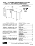
INSTALLATION AND OPERATION INSTRUCTIONS
SINGLE KEG BEER DISPENSER
MODEL NOS.
DP32S
DS32S
Table of Contents
IMPORTANT INFORMATION
A Warranty card is enclosed that must be filled out
and mailed to the Perlick Corporation in order to register the warranty. If the card is not returned to
Perlick, the warranty period will begin from the date
the equipment is shipped from the factory.
This manual has been prepared to assist you in the
installation of your Single Keg Dispenser and to
acquaint you with its operation and maintenance.
We dedicate considerable time to ensure that our
products provide the highest level of customer
satisfaction. If service is required, your dealer can
provide you with a list of qualified service agents. For
your own protection, never return merchandise for
credit without our approval.
We thank you for selecting a Perlick product and
assure you of our continuing interest in your
satisfaction.
WARNING: When lifting, the full weight of the
cabinet must be supported. Lift from the cabinet
base and not from the top. Improper lifting can
result in severe damage to the cabinet.
PREPARING THE CABINET FOR USE
Specifications.........................................................2
List of Included Parts.............................................3
Tools Required.......................................................3
Plumbing................................................................3
Electrical ................................................................3
Uncrating ...............................................................3
Installing Casters ...................................................3
Placing the Cabinet ...............................................3
Leveling the Cabinet..............................................3
Installing Faucet and Dispensing Head.................3
TAPPING
Connecting the Keg Coupler .................................4
Tapping the Keg.....................................................4
Connecting the Regulator......................................4
Adjusting Gas Flow................................................4
CO2 Leak Test .......................................................5
Replacing a CO2 Gas Cylinder..............................5
Handling CO2 Gas .................................................5
TEMPERATURE
Beer Temperature ..................................................6
Refrigeration and Temperature Control .................6
Adjusting the Temperature.....................................6
CLEANING
Cleaning the Beer System.....................................7
Cleaning the Cabinet .............................................7
Cleaning the Condenser........................................7
Condenser .............................................................7
GENERAL INFORMATION
How to Pour a Perfect Glass of Beer ....................8
Troubleshooting .....................................................9
REPLACEMENT PARTS ................................10-11
Wiring Diagram....................................................12
8300 West Good Hope Road • Milwaukee, WI 53223 • Phone 414-353-7060 • Fax 414-353-7069
Toll Free 800-558-5592 • E-Mail: [email protected] • www.Perlick.com
Form No. Z2268
Installation and Operating Instructions
Sizes and Specifications, Single Keg Beer Dispensers
MODEL NUMBERS
CABINET STYLE
HALF BARREL CAPACITY
AMPS
SHIP WT lbs. (kg)
DP32S
Portable
1 Keg
2.7
222 (101)
INTERIOR
DS32S
Underbar
1 Keg
2.7
216 (98)
Door Pan & Ceiling: High strength polystyrene. Door Sill: High strength polyethylene.
Floor Pan: Stainless steel. Walls: Galvanized steel.
Stainless steel top, back, sides and front. Galvanized bottom. Condensing unit grille
stainless steel. Decorative handle. Right hinged door standard from factory. Door
hinging is field reversible.
R-134a capillary tube-type. Aluminum fin and copper tube evaporator coil.
Adjustable temperature control. Self-defrosting.
Front ventilated.
115 Volt, 60 Hz., 1 Phase AC. Furnished with three-prong, six foot NEMA 5-15P cord.
Contact Perlick-Milwaukee for other voltage/frequency requirements.
3/4” NPT drain exits out right end or 1” NPS out bottom.
• Leg Set
• Caster Sets
EXTERIOR
REFRIGERATION
VENTILATION
ELECTRICAL
PLUMBING
OPTIONAL ACCESSORIES
20 1/8”
[511]
16”
[406]
23 3/16” R
[589]
11 15/16”
[334]
TOP VIEW
24 3/4”
[699]
12 3/4”
[324]
19 7/8”
[505]
OPENING
27 1/4”
[692]
2 3/4”
[70]
32”
[813]
FRONT VIEW
34 1/2”
[876]
27 1/2”
[699]
OPENING
4 3/16”
[94]
1 1/8”
[29]
END VIEW
4 1/16”
[103]
CORD EXIT
2 1/16”
[52]
BACK VIEW
Perlick is committed to continuous improvement. Therefore, we reserve the right to change specifications without prior notice.
Form No. Z2268
2
Preparing the Cabinet for Use – Single Keg Beer Dispensers
Parts List
■
■
■
■
■
■
■
■
Installing Casters
Casters* .
Faucet Standard.
Faucet Head Assembly.
Spanner Wrench for Faucet.
Black Connector Hose 3⁄16” x 3’.
5
⁄16” Air Hose.
Bag of Miscellaneous Parts.
Plastic Waste Bottle.*
Attach four casters to the cabinet bottom; rigid
casters at the rear and swivel casters on the front.
Use the supplied 1/ 4”- 20 x 3/ 4” hex head selftapping machine screws.
Placing the Cabinet
Push the cabinet into place using rollers when
necessary. Important: Proper air flow around the
condensing unit is necessary for efficient operation.
Never obstruct the air flow in and out of the
condensing unit.
* Portable Model Only.
Suggested Tools
■
■
■
■
■
■
(Portable Models Only)
#2 Phillips Screwdriver.
Spanner Wrench (included).
10” Crescent Wrench.
9/ 16” Allen Wrench.
5/ 16” and 3/ 8” Hex Socket.
Power drill or driver.
Leveling the Cabinet
When the cabinet is in place, check installation with
carpenter’s level. When perfectly level, accumulated
water will drain out. A slight pitch to the drain side
will not harm the cabinet. Water may accumulate if
cabinet is pitched to the opposite side.
Plumbing
Installing the Faucet and
Dispensing Head
Portable Model
No plumbing connections are required. Condensate
from the cooling coil is automatically evaporated.
Drain pan waste is accumulated in the plastic bottle
installed inside the cabinet.
Underbar Model
Features a floor drain with a 3⁄4” female pipe thread
connection for disposal of both condensate and
drip pan waste. Remove bottom 1” NPS or side 3⁄4”
drain plug attach male pipe to create external drain.
Before you begin: Wash dispensing head and
faucet. Flush beer, dispensing head and faucet
lines with fresh water.
■ Apply RTV around the base of the dispensing
head to seal it to the top. Align the dispensing
head over the five holes on the cabinet top
and use the five stainless steel #10-32 x 13⁄4”
Phillips pan head stainless steel machine
screws to secure standard to cabinet top.
Wipe off excess RTV to complete the seal.
■ Attach faucet to standard using spanner
wrench to tighten coupling. Attach faucet
handle to faucet.
■ Insert flexible plastic air hose six to seven
inches into bottom of faucet standard.
Secure hose with tie wrap (supplied).
Electrical
The cabinet must be connected to a separately
fused power source (see electrical specification
plate) and grounded in accordance with National
and Local Electrical Codes. Caution: Do not
attempt to operate the equipment on any other
power source than that listed on the Electrical
Specification plate.
Uncrating and Inspection
WARNING!
Remove all crating material before operating.
Carefully inspect cabinet for hidden damage. If
damage is discovered, file your claim immediately
with the transportation company. Perlick is
not responsible for damage in transit.
To avoid compressor damage, after returning
cabinet to an upright position, let unit stand for 24
hours before plugging it in and running the unit.
Perlick is committed to continuous improvement. Therefore, we reserve the right to change specifications without prior notice.
Form No. Z2268
3
Installation and Tapping – Single Keg Beer Dispensers
Connecting the Keg Coupler
(when Supplied by Perlick)
■
■
■
■
Connecting the Regulator to the
CO2 Cylinder
■
Place one brown leather washer into black beer
line connector hose on hex nut side. Screw
connector to stainless steel beverage line on
faucet standard. Tighten with a wrench, but do
not over tighten.
Make sure lever handle on the keg coupler is in
the UP (untapped) position. Place one brown
leather washer into wing nut end of black beer
line connector hose and thread onto top of keg
coupler. Hand tighten.
Place clamp on one end of red air line. Push
end over air valve located inside cabinet.
Tighten clamp with screwdriver. Turn shut-off
valve to OFF (horizontal) position.
Place clamp on the other end of red air line and
push over tailpiece on coupler. Tighten clamp
with screwdriver.
CAUTION: Do not use keg coupler as a
handle to lift keg.
■
■
Remove blue plug from regulator fitting.
(Note: Do not remove the carbonic washer).
Screw regulator onto gas cylinder valve. Tighten
with wrench until vertically straight. Be sure that
shut-off valve (black lever) on regulator is in
the OFF (horizontal) position.
Place a screw clamp over end of red air line
and push onto regulator tailpiece. Tighten clamp
with a screwdriver.
CO2
PRESSURE
GAUGE
REGULATOR
FITTING
20
30
HAND
VALVE
40
PERLICK
50
10
PSI
0
60
CO2
GAS
DRUM
Tapping a Single Valve Keg (Sankey):
FITTING FOR
RED AIR HOSE
Step 1
SHUT-OFF VALVE
(BLACK LEVER IN
CLOSED POSITION)
REGULATOR
ADJUSTING
SCREW
Single Valve Keg Coupler
OUT
Step 3
Adjusting the CO2 Gas Flow
DOWN
Step 2
■
■
1/4
TURN
■
■
■
■
■
Be sure beer faucet is in closed position.
Align keg lugs with lug openings on bottom
of coupler.
Turn clockwise 1⁄4 turn. Pull handle out and
down. Keg is now tapped.
Open shut-off valve on air distributor located
inside of the cabinet.
Important: Be sure to close this valve
when untapping keg.
■
Turn regulator adjusting screw counterclockwise
until it turns freely.
Turn hand valve counterclockwise on CO2
cylinder to the fully open position.
Turn regulator adjusting screw clockwise until
desired pressure is reached (approximately
12-15 lbs.). Tighten stop nut on adjusting screw.
Open shut-off valve on bottom of regulator.
Perlick is committed to continuous improvement. Therefore, we reserve the right to change specifications without prior notice.
Form No. Z2268
4
Installation and Tapping – Single Keg Beer Dispensers
CO2 Leak Test
■
Dilute a small amount of liquid dishwashing soap
and rub the soapy mixture around each connection.
If bubbles appear, tighten connection.
■
NEVER...
Replacing CO2 Gas Cylinder
■
■
■
■
■
or dirt before attaching regulator.
Store CO2 cylinder and regulator assembly
upright.
Allow only properly trained and experienced
personnel to handle high pressure gas.
■
Turn CO2 hand valve clockwise until seated and
close shut-off valve on regulator.
Unscrew regulator from cylinder fitting.
Replace carbonic washer (Part No. 157F2P),
if needed and reattach regulator to filled
cylinder.
Turn CO2 hand valve counterclockwise until
fully open. Turn regulator shut-off valve to
open position.
Adjust CO2 gas flow as required, turning
clockwise for higher pressure.
■
■
■
■
■
Connect cylinder directly to a keg without a
regulator (reducing valve).
Drop or throw regulator or CO2 cylinder.
Transport CO2 cylinder in a closed vehicle.
Apply oil to a regulator.
Shut off CO2 cylinder when not in use. You will
not save gas by doing so!
Allow untrained, inexperienced personnel to
handle high pressure gas.
Failure to heed this warning could result in
personal injury or death.
Proper CO2 Handling
ALWAYS...
■
■
■
■
■
■
Connect a regulator (reducing valve) to
CO2 cylinder.
Secure cylinder in upright position whether in
storage or in use.
Keep cylinder away from heat. Rupture disc
vents at 122° F. maximum.
Ventilate room after high pressure gas leakage.
Check the last DOT test date on cylinder neck
before filling. If more than five years old, the
cylinder must be retested to DOT specifications.
Be sure CO2 cylinder outlet fitting is free of dust
Perlick is committed to continuous improvement. Therefore, we reserve the right to change specifications without prior notice.
Form No. Z2268
5
Draft Beer Information – Single Keg Beer Dispensers
Temperature
At temperatures lower than 30° F., beer will freeze.
When beer freezes, the alcohol in the beer may
separate and cause the beer to be cloudy with an
“off” taste.
One of the most common causes of dispensing
problems is improper temperature. Draft beer
should be stored at a temperature between 32° and
38°. At warmer temperatures, beer will foam.
Draft beer is not pasteurized and must be kept cool at all times.
Refrigeration and Temperature Control
Adjusting the temperature
The Partymaster Dispenser is equipped with a
heavy-duty refrigeration system designed to
automatically maintain a storage temperature of
36-41 degrees F. The control is factory set at 38
degrees F.
The temperature control is inside the cabinet on
the right-hand side of the evaporator fan panel
assembly. You will need a screwdriver to turn the
adjusting screw. Make small adjustments until the
desired temperature is achieved.
■ Colder Temperatures:
Turn the adjusting screw clockwise (to the right).
■ Warmer Temperatures:
Turn the adjusting screw counterclockwise
(to the left).
In normal operation the condensing unit will turn on
and off, depending on the cooling load required.
The condenser fan motor turns off and on with the
condensing unit. The evaporator fan motor runs
continuously. The fan motors are lifetime lubricated
and will require no oiling.
NOTE:
Cabinet Temperatures lower than 34° will not allow
for proper defrosting of the evaporator coil. If
defrosting is necessary, turn the control knob to the
OFF position until coil is defrosted.
Perlick is committed to continuous improvement. Therefore, we reserve the right to change specifications without prior notice.
Form No. Z2268
6
Cleaning the Beer System – Single Keg Beer Dispensers
■
The entire beer system, to include the faucet, flexible
beer line and tapping devices must be cleaned at
regular intervals. We recommend flushing the entire
system with fresh water immediately after a keg has
been emptied. Once each month the system should
be cleaned chemically.
It is recommended that you purchase Perlick’s
Pump Type Sterilizer, as shown below. It is
equipped with an adapter that attaches directly to
the faucet shank in lieu of the faucet. It is also
available with a slip coupling for those who choose
to clean their faucets in place.
Part Nos.
887P
887PSC
848A33
Description
1
⁄2 Gallon sterilizer w/faucet coupling.
1
⁄2 Gallon sterilizer w/slip coupling.
33 oz. liquid alkaline cleaner.
Beer Stone:
All beer contains calcium which is present from
the grains used in the brewing process. it is an
important natural material in draft systems in
that as it oxidizes it coats the internal parts of
the beer lines and equipment. This thin coat of
beer stone helps prevent the beer from picking
up strong metallic or plastic flavors as it flows
through the system. The beer stone will
continue to build if the system is not cleaned
properly or regularly and can cause drawing
problems if it begins to flake off. Beer stone is
present if one can see a brownish color on the
faucet or inner wall of the beer line, or tobaccolike flakes in the beer.
Cleaning the Cabinet
Cleaning the draft beer system
will help to eliminate the build-up
of the following materials:
■ Bacteria:
Beer is an excellent food for
bacteria (none of which is
harmful). Proper conditions
may begin the growth of
bacteria in draft beer and on
the beer faucet. By regular
cleaning, we prevent this
bacterial buildup and
maintain the quality of the
No. 887P
draft beer. Greenish or yellowish colored material on the faucet may indicate
bacterial growth.
■ Yeast:
All domestic draft beers contain a small amount
of yeast which remains in the beer from the
fermentation process. When the temperature of
draft beer exceeds 50° a process of secondary
fermentation may take place. The beer faucet
may exhibit a white colored substance (yeast
build up) if not cleaned on a regular basis.
Use a mild detergent and water to clean the inside
and outside of the cabinet. Dry thoroughly. Never
use a scouring pad or abrasive cleanser.
NOTE: An industrial strength, commercial cleaner
can be used to clean the outside of painted
cabinets.
Cleaning the Condenser
Use a long handled, stiff brush to clean the dirt from
the front surface of the condenser. Keeping the
condenser free from dust and dirt will ensure efficient operation.
CAUTION: Do not bend the fins while brushing the
front of the condenser.
Condenser
The condenser (located behind the back cover)
should be inspected every 30 days and cleaned, if
necessary. Failure to keep the condenser clean will
cause a loss in condensing unit efficiency.
Perlick is committed to continuous improvement. Therefore, we reserve the right to change specifications without prior notice.
Form No. Z2268
7
Pouring a Perfect Glass of Beer – Single Keg Beer Dispensers
STEP 1
➠
Start with a clean glass.
Place the glass at a
45° angle, one inch
below faucet. Do not
let the glass touch the
faucet. Open the faucet
all the way.
STEP 2
➠
After the glass has
reached half full,
gradually bring the
glass to the upright
position
STEP 3
➠
Let the remaining beer
run straight down the
middle of the glass.
This ensures proper
release of CO2 by
producing a 3⁄4” to 1”
foam head.
STEP 4
➠
Close the faucet quickly
and completely.
Perlick is committed to continuous improvement. Therefore, we reserve the right to change specifications without prior notice.
Form No. Z2268
8
Trouble Shooting – Single Keg Beer Dispensers
Beer Service Problems
■
■ Cloudy Beer:
Beer in glass appears hazy, not clear.
CAUSES:
■ Dirty glass.
■ Dirty faucet or beer line.
■ Frozen or nearly frozen beer.
■ Old beer.
■ Beer that has not been refrigerated for a
long period of time.
Wild Beer:
Dispensed beer has either too much foam or
is all foam.
CAUSES:
■ Beer has been dispensed improperly.
Solution: See pouring instructions
on page 8.
■ Regulator pressure is set too high.
■ Warm keg temperature.
Solution: Keg must be colder than
40°. Target temperature is between
36° and 38° F.
■ Cabinet door is opened and closed
frequently and temperature is warmer
than 38° F.
Solution: Adjust temperature to between
36° and 38° F.
■ Kinks, dents or obstructions in the line.
■ Using oddly shaped glasses. Frosted,
waxed or styrofoam containers may
cause foaming.
■ Dispenser has been turned off for a
long period of time.
■ Faucet is bad, dirty or in a worn condition.
■ Regulator malfunction.
Beer and CO2 Facts
Keg
Size
Quarter
Half
■
■
■
■
■
No. of
Gallons
No. of
Oz.
No. of
Cases
73⁄4
151⁄2
992
1,984
3.445
6.889
No. of
Full Keg
12Oz.
Weight
Servings
105
87 lbs.
210
161 lbs.
Beer foam is 25% liquid beer and 75% CO2
gas. Don’t waste it!
Most people prefer beer stored at 38° F.
Beer lines and faucets require regular cleaning
(see cleaning instructions on page 7).
A fully-charged 4.2 lb. CO2 cylinder will
dispense approximately 51⁄2 to 61⁄2 half barrels.
CO2 gas gives beer its sparkling effervescence.
It also gives beer its creamy head of foam.
■ Flat Beer:
Foamy head disappears quickly; beer lacks
brewery fresh flavor.
CAUSES:
■ Dirty glassware.
■ CO2 pressure is too low, due to leak or
pressure setting.
■ CO2 is turned off at night.
■ Cooler is too cold.
■ CO2 leak or defective (sticking)
check valve.
■ Sluggish CO2 regulator.
Perlick is committed to continuous improvement. Therefore, we reserve the right to change specifications without prior notice.
Form No. Z2268
9
Replacement Parts – Single Keg Beer Dispensers
MODEL NOS.
Item Description
1
Compressor for R134a
2
Condenser fan motor
3
Condenser fan motor bracket
4
Condenser fan blade
5
Side panel
6
Front grille
7
Condenser
8
Evaporator fan blade - 4”
9
Evaporator fan motor
10
Evaporator assembly - complete
11
Top assembly
12
Temperature control
13
Door assembly
14
Magnetic door gasket
15
Door sill
16
Door handle
16A Door handle bracket
17
Swivel caster
18
Waste bottle
19
Waste bottle holder
20
Drip pan assembly
20A Drain insert
21
Dispensing head draft arm complete w/ Faucet
21A Faucet
Parts Not Shown on Drawing
Wiring harness
Power cord
Top evaporator
Top
Liquid and Suction line assembly
DP32S & DS32S
Part #’s
63778
63807
65166-1
63808
66215-1SS
66210-8SS
65528
63461
C15239A
66295
66230-32T
61271
66256-1
66237-4
65500-1
C31409-1
65189-1
57788
C24392-1
65524-1
65507
65510-1
63251
408X
65531
65532
65532
65529
21 21A
20
12
8 9 10
20A
18 19
11
14 16
16A
5
1
15
6
2
3
4
7
13
17
Perlick is committed to continuous improvement. Therefore, we reserve the right to change specifications without prior notice.
Form No. Z2268
10
Replacement Parts – Single Keg Beer Dispensers
For Single Valve Keg Coupler (Series D)
14
4
Item
Part
No.
No.
Description
1 .............32499................Probe assembly
2 ............F40184...............Probe body
3...........31080-2P.............Ball
4............43641-1 ..............Ball retainer
5...........31087-2P.............Probe washer
6 .............31089................“O” Ring - 3-per assembly
7 .............43061................Body
8...........23682-2P.............Check valve
9............157R2P ..............Washer
10............206B-1...............Tailpiece
11..............2026.................Coupling nut
12..........31088-2P.............Bottom seal washer
13...........31084-1 ..............Retaining screw
14 ...........43002A...............Yoke assembly w/lock
15 ...........43001A...............Yoke assembly standard
16...........32474-1 ..............Wrench
3
1
2
15
13 6
11
10
9
8
7
12
5
16
Miscellaneous
Part
No.
Description
157L2P................Beer line connector gasket
57F2P .................CO2 tank washer
1392R .................Red air hose
529 ......................Beer hose
2928D .................Twin gauge CO2 regulator
Perlick is committed to continuous improvement. Therefore, we reserve the right to change specifications without prior notice.
Form No. Z2268
11
Wiring Diagram – Single Keg Beer Dispensers
EVAPORATOR FAN
BLACK
WHITE
THERMOSTAT
BLACK
RED
BLACK
WHITE
JUNCTION
POINTS
POWER CONNECTION
CONDENSER FAN
WHITE
COMPRESSOR
BLACK
WHITE
GREEN
RED
OVERLOAD
NEMA–15P CORD
RELAY
WHITE
END VIEW
GR
EEN
8300 West Good Hope Road • Milwaukee, WI 53223 • Phone 414-353-7060 • Fax 414-353-7069
Toll Free 800-558-5592 • E-Mail: [email protected] • www.Perlick.com
Perlick is committed to continuous improvement. Therefore, we reserve the right to change specifications without prior notice.
12
Form No. Z2268