1
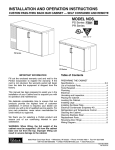
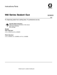
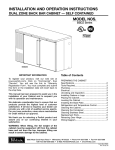
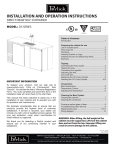
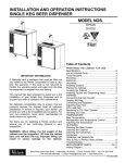
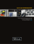
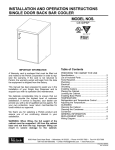
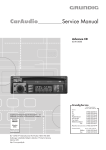
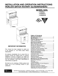
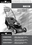
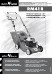
INSTALLATION AND OPERATION INSTRUCTIONS
SINGLE DOOR FREEZER
MODEL NOS.
■ F24N
■ F24S
Finished Stainless
Steel Top
F24S
IMPORTANT INFORMATION
This manual has been prepared to assist you in the
installation of your Single Door Freezer and to
acquaint you with its operation and maintenance.
We dedicate considerable time to ensure that our
products provide the highest level of customer
satisfaction. If, however service is required, call
Perlick at 1-800-777-7267 or your dealer who can
provide you with a list of qualified service agents. For
your own protection, never return merchandise for
credit without our approval.
We thank you for selecting a Perlick product
and assure you of our continuing interest in
your satisfaction.
IMPORTANT WARRANTY INFORMATION
Non-Finished
Top
F24N
Table of Contents
Cabinet Specifications ..........................................2
Installing
Uncrating and Inspection ................................3
Plumbing .........................................................3
Electrical..........................................................3
Placing The Cabinet........................................3
Installing Casters or Legs ...............................3
Anti-Tip ............................................................3
Sealing the Floor.............................................3
Defrost System .....................................................4
Temperature Control .............................................4
Cleaning the Condenser .......................................5
Cleaning the Cabinet ............................................5
Cleaning Stainless Steel/Avoiding Corrosion .......5
Replacement Parts ............................................6/7
Wiring Diagram .....................................................8
A Warranty card is enclosed that must be completed
and mailed to the Perlick Corporation in order to
register the warranty. If the card is not returned to
Perlick, the warranty period will begin from the date
the equipment is shipped from the factory.
8300 West Good Hope Road • Milwaukee, WI 53223 • Phone 414-353-7060 • Fax 414-353-7069
Toll Free 800-558-5592 • E-Mail: [email protected] • www.Perlick.com
Form No. Z2255
Rev. 08.22.06
Sizes and Specifications
Single Door Freezer
MODEL NOS.
F24NB
F24SB
F24NS
F24SS
CABINET
Length
24” (610)
24” (610)
DIMENSIONS Depth
24 1⁄ 4” (615)
24 1⁄ 4” (615)
(mm)
Height
34 1⁄ 2” (887)
34 1⁄ 2” (887)
INTERIOR CU. FT. (m3)
4.9 (0.14)
4.9 (0.14)
GLASS CAPACITY*
86
86
CONDENSING UNIT H.P.
1/5 HP
1/5HP
RUNNING LOAD –AMPS
2.0
2.0
Ship Wt. Lbs. (kg.)
145 (54)
145 (54)
INTERIOR
Both models: Interior liner is stainless steel. Includes two adjustable vinyl coated shelves plus
a bottom rack.
EXTERIOR:
Back, top and sides are Galvanized steel.
Top and sides are stainless steel.
Back is galvanized steel.
Both models: Front is stainless steel. Doors: Either black vinyl CRS or stainless steel.
Bottom: galvanized steel with stainless grille.
REFRIGERATION
R-134A capillary tube-type. with hermetic condensing unit. Front access for condenser and cleaning.
ELECTRICAL
115V, 60Hz., 1 phase . Furnished with 3-prong, 6 foot rubber plug in cord.
PLUMBING
None required. Moisture drains to self evaporating condensate pan in machinery compartment.
INSULATION
2” foamed-in-place polyurethane insulation.
TEMPERATURE RANGE Adjustable from -10° to +10° F (-23° to-12° C).
VENTILATION
Front vented.
DEFROST SYSTEM
Solid state, push button defrost system, manually initiated at end of each day, automatically
terminates after six hours. Hot gas automatic defrost every 4 hours for approximately 20 minutes
(time/temperature terminated).
OPTIONAL
• Set of 4 casters (33⁄ 4” high) P/N 65426.
ACCESSORIES &
• Set of 4 adjustable legs (6” - 71⁄ 4” high) P/N 65423.
* Capacity calculations based on use of 3” diameter glasses on standard shelving.
47 1/8”
[1197]
24”
[610]
24 1/4”
[615]
18 1/2”
[470]
20”
[508]
FINISHED
STAINLESS
TOP
8” [203]
34 1/2”
[887]
8” [203]
30 9/16”
[776]
11 3/4”
[470]
8 7/16” [214]
180°
DOOR SWING
5 9/16”
[141]
3 11/16”
[92]
TopView
29 1/4”
[743]
Front View
NON-FINISHED
TOP
End View
Perlick is committed to continuous improvement. Therefore, we reserve the right to change specifications without prior notice.
2
Form No. Z2255
Rev. 08.22.06
Preparing the Cabinet – Single Door Freezer
THE ANTI-TIP BRACKETS MUST CATCH EACH
OF THE LEVELING LEGS TO HAVE A STABLE
AND SAFE INSTALLATION.
Some installation sites might need to be modified to
provide a secure surface for attaching the bracket.
Refer to the illustration below for anti-tip mounting
bracket locations.
Uncrating and Inspection
Remove all crating material before operating.
Carefully inspect cabinet for hidden damage. If
damage is discovered, file your claim immediately
with the transport company. Perlick is not
responsible for damage in transit.
Plumbing
NOTE: Do not extend leveler leg
more than 3/4” out of base. Do not
shim or pad to obtain levelness.
No plumbing connections are required. Condensate
from the cooling coil is automatically evaporated
through a condensate pan located in the
condensing unit section.
Ø 3/8”
Surface
mounts
to floor.
1 1/2”
20 7/8”
Electrical
Cabinet must
have at least
5/16” clearance
from floor to
accomodate
brackets.
7/16”
The cabinet must be connected to a separately
fused power source (see Electrical Specification
Plate) and grounded in accordance with National
and Local Electrical Codes.
CAUTION: Do not attempt to operate the equipment
on any other power source than that listed on the
Electrical Specification Plate.
Shown with leg
leveler engaged
in anti-tip bracket.
Placing the Cabinet
TOP VIEW
To assure maximum performance, fresh air must
be allowed to circulate through the machinery
compartment. Do not place anything in front of the
cabinet that would obstruct air flow at these grilles.
Do not place the unit in an unventilated small room.
Cabinet should be leveled front to back and side
to side.
Sealing the Cabinet
For sanitation purposes, it may be necessary to
seal the base of the cabinet to the floor. This can be
accomplished by laying a bead of silicone sealant
between the base of the cabinet and the floor as
shown by the figure below.
When sealing the cabinet to the floor, make sure
that the louvered front grille plate can still be
removed for condenser maintenance and cleaning.
Installing Casters or Legs (optional)
Attach casters or legs to the mounting bracket
with the lockwashers and 1⁄4”–20 hex head nuts
provided. Attach bracket and leg/caster assembly to
the side of the cabinet base using the 1⁄4”–20 hex
head self-tapping machine screws provided.
CABINET
Anti-tip (without Legs or casters)
To prevent the cabinet from tipping forward and to
provide a stable installation, the cabinet must be
secured in place with an anti-tip device.
A set of metal anti-tip brackets and installation
screws (#10-3⁄4” wood screws) are supplied. These
brackets should be attached to the floor, at the
back of the cabinet; each bracket located to catch
each rear leveling leg when the cabinet is pushed
backward into position.
BEAD SILICON
SEALER (RTV)
FLOOR
Perlick is committed to continuous improvement. Therefore, we reserve the right to change specifications without prior notice.
3
Form No. Z2255
Rev. 08.22.06
Operation Instructions – Single Door Freezer
Defrost System - Hot Gas Defrost
Temperature Control
This system consists of a six-hour, as well as a
four-hour defrost cycle which includes a 20 minute
evaporator defrost. The six-hour defrost cycle is
manually activated and automatically terminated,
while the four-hour cycle is completely automatic.
An adjustable temperature control is located inside
the freezer on the evaporator fan panel
assembly. Approximate temperature operating
range: minus 15° F. minimum and plus 10°F
maximum. Make adjustments as shown to attain
the desired temperature.
■ Colder Temperatures: Turn the adjusting
screw clockwise (to the right).
■ Warmer Temperatures: Turn the adjusting
screw counterclockwise (to the left).
■ Temperature Control “OFF”: Turn the
adjusting screw completely counterclockwise to the “O” position until a click is noted.
The condenser fan and the evaporator fan motor
turns off and on with the compressor.
■ The Six Hour Solid-State Defrost Timer:
This timer shuts off the power to the
condensing unit, the evaporator fan, and
the automatic four hour defrost timer.
To activate the six hour defrost system,
depress the defrost switch located on the
front grille of the cabinet. An amber light will
illuminate and the defrost cycle will begin.
When the defrost cycle ends, the light
goes off and the cabinet resumes normal
operation. To manually cancel the defrost
cycle, momentarily turn off the electricity to
the unit.
NORMAL
5
6
4
COOLER
8
9
1
This timer ensures that frost will not buildup on
the evaporator coil. Every four hours the hot gas
by-pass valve is opened and hot gas is
circulated through the evaporator coil. The
defrost is terminated when the coil is clear of
frost. The defrost cycle lasts for approximately
20 minutes.
During normal operation it is recommended that
the doors are not left open to prevent excessive
frost buildup on the coil.
7
3
2
WARMER
■ The Four Hour Defrost Timer:
0
CONDENSING UNIT
Perlick is committed to continuous improvement. Therefore, we reserve the right to change specifications without prior notice.
4
Form No. Z2255
Rev. 08.22.06
Cleaning Instructions – Single Door Freezer
Cleaning the Condenser:
Avoiding Stainless Steel Corrosion
■ The Condenser (located behind the front
grille) should be inspected every 30 days,
and cleaned, if necessary. Failure to keep
the condenser clean will cause a loss in
condensing unit efficiency, or compressor
failure.
CAUTION: Do not bend the fins while
brushing the front of the condenser.
Corrosion can be prevented by following product
cautions, cleaning instructions and avoiding use
of certain chemicals or objects which will cause
stainless steel corrosion.
STAINLESS STEEL ENEMY
■ Steel wool or steel scouring pads
■ Cherry/Orange/Olive juice
■ Chlorine Bleach
■ Sharp Objects
Cleaning the Cabinet:
■ Use a damp cloth and a mild detergent and
water to clean the inside and outside of the
cabinet. Dry thoroughly. Do not allow cleaning
agents or large amounts of water to go down
the drain. Uae an acceptable stainless steel
polish to clean all stainless steel surfaces.
Never use steel wool, scouring pad or abrasive
cleanser.
NOTE: An industrial strength, commercial
cleaner can be used to clean the outside of
painted cabinets
Perlick is committed to continuous improvement. Therefore, we reserve the right to change specifications without prior notice.
5
Form No. Z2255
Rev. 08.22.06
Replacement Parts – Single Door Freezer
21
13
10 11
19
14
17
16
15
12
36
6
1
22
20
22
24
18
2 3 4
5
9
23
7
25
33
8
CAUTION
■ Service should be done by a qualified
refrigeration technician.
■ Disconnect all power before servicing
the cabinet.
Perlick is committed to continuous improvement. Therefore, we reserve the right to change specifications without prior notice.
6
Form No. Z2255
Rev. 08.22.06
Replacement Parts – Single Door Freezer
MODEL NOS.
Item Description
1
Compressor for R134A
2
Condenser fan motor
3
Condenser fan motor bracket
4
Condenser fan blade
5
Condenser fan shroud
6
Rear panel
7
Front grille
8
Condenser coil
9
Condenser pan
10
Evaporator fan guard
11
Evaporator fan motor
12
Evaporator assembly, complete
13
Top overlay
14
Temperature control with dial plate
15
Door assembly
16
Magnetic door gasket
17
Shelf
18
Shelf, bottom
19
Pilaster
20
Shelf clip
21
Evaporator grille
22
Tip over bracket
23
Door handle
24
Bypass valve/solenoid assembly
25
Defrost switch
26
Solid state controller
27
Time delay relay
28
Defrost terminator
29
Power cord wiring harness
30
Evaporator assembly wiring harness
31
Relay wiring harness
32
6 Hour defrost wiring harness
33
Leg kit set of 4 includes brackets
34
Caster kit set of 4 including brackets
35
Complete hinge set-left
36
Complete hinge set-right
(not shown)
(not shown)
(not shown)
(not shown)
(not shown)
(not shown)
(not shown)
(not shown)
(not shown)
ALL MODELS
Part Numbers
63778
C15239A
60988-1
C22370
65206-2
65159-1
65158-1
65252
65473
65254
65253
H66136F
65429-1SS
61282
66223 or 66223SS
66237-1
66236-1
64809-1
C19271-1
C15875
66139-2
63740-1
C31409-1
63717
C31659
57466
63794
57676
65470
65475
65476
61959
65423
65426
66153L
66153R
Perlick is committed to continuous improvement. Therefore, we reserve the right to change specifications without prior notice.
7
Form No. Z2255
Rev. 08.22.06
WHITE
Wiring Diagram – Single Door Freezer
EVAP
FAN
A2 RED
NORMAL CLOSED
HOT GAS DEFROST
SOLENOID
TEMPERATURE
CONTROL
DEFROST CYCLE:
1) AFTER 220 MINUTES:
• A2 OPENS.
• B1 CLOSES.
• HOT GAS VALVE OPENS.
• ON DELAY RELAY CONTACT
CLOSES 1 TO 2, IN 3 MINUTES.
• THERMOSTAT IS BYPASSED.
• COMPRESSOR RESTARTS AFTER
3 MINUTES FOR HOT GAS DEFROST.
OPEN
@ 40° F
BLACK
RED
DEFROST
TEMP. LIMIT
SWITCH
CLOSE
@ 25° F
1
2
BLACK
ON DELAY
RELAY
3
WHITE
A1
A
A2
RELAY
3
4
W
B
2
2) LIMIT SWITCH OPENS AT 40° F:
• COMPRESSOR POWER OFF.
• HOT GAS REMAINS ENERGIZED.
3) AFTER 20 MINUTES:
• B1 OPENS.
• HOT GAS VALVE IS DE-ENERGIZED.
• A2 CLOSES.
• COMPRESSOR STARTS THROUGH
TEMPERATURE CONTROL.
B2 B1 T11 T12 T13
RELAY
B (POWER)
INTERNAL
CONNECTIONS
WHITE
WHITE
COND
FAN
T14
T15
S.S. TIMER
1
TO CONDENSING
UNIT
4
2
5
3
6
S.P.S.T. MOMENTARY
CONTACT DEFROST SWITCH
W/ INDICATOR LIGHT
PLUG-IN-CORD
8300 West Good Hope Road • Milwaukee, WI 53223 • Phone 414-353-7060 • Fax 414-353-7069
Toll Free 800-558-5592 • E-Mail: [email protected] • www.Perlick.com
Perlick is committed to continuous improvement. Therefore, we reserve the right to change specifications without prior notice.
Form No. Z2255
Rev. 08.22.06