1
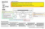
Expand Your Factory Radio
add
iPod
®
GM
Owner’s
Manual
Owner’s Manual
Media Gateway
PXAMG
Media Gateway
PGHGM3
PXAMG
Peripheral Electronics®®,
a division of AAMP of America™
13160 56th Court Clearwater, Florida 33760
Ph. 800-477-2267
866-788-4237 ext. 230
[email protected]
©2007 AAMP of Florida, Inc.
©2008
Rev. 05-01-08
INST013
Table of Contents
1. Introduction
Pages
1
2. Precautions
1
3. Compatibility
1
4. Dipswitch Settings
2
5. Installation
2
6. iPod Operation
3
7. HD Radio Operation
(if equipped)
5
8. Selecting AUX Input
6
9. Selecting Factory Satellite
(if equipped)
7
10. Troubleshooting
7
11. Warranty Information
8
Media Gateway & Optional Add-ons
Factory Radio
Not Included
iPod
Not Included
Media Gateway Harness
Part #: PGHGM3
Media Gateway
Part #: PXAMG
11Ft. iPod Cable
3Ft. HD Radio Cable
Antenna Adapter
HD RadioTM Tuner
(sold separately)
Part #: HDRT
* Required for most vehicles. (sold seperately)
1. Introduction
Thank you for purchasing the Peripheral Electronics® Media Gateway.
The Media Gateway is designed to provide endless hours of listening
pleasure from your factory radio. To ensure that your iPod performs
correctly with your radio, we recommend that you read this entire manual
before attempting installation of the Media Gateway.
The Media Gateway allows connectivity for iPod and the HD Radio tuner
(HDRT sold separately), enabling full control of these devices from the
factory installed radio. It also retains original system features such as
Satellite Radio(if equipped).
2. Precautions
UPDATING iPod FIRMWARE
For proper operation of the Media Gateway, your iPod must be updated with the
most recent version of firmware from Apple. This is done on your computer. To
update the software on the iPod go to: http://www.apple.com/ipod/download/.
Follow the directions on the website to complete the download. There is no
charge for this update.
PREVENTING DAMAGE TO YOUR VEHICLE OR iPod.
Some installations require you to make wiring connections. To eliminate the
risk of an electrical short, we recommend disconnecting the vehicle’s battery
prior to installation. If you do not feel comfortable making these connections,
we suggest you seek professional installation. We recommend that the iPod
be disconnected from the interface when the vehicle is not in use.
PROPER MOUNTING LOCATION
Securely install the interface in a location free from; heat, humidity, moving
parts, sharp metal edges or direct sunlight. We recommend securing the
interface to a suitable location using; double sided tape, VelcroTM or zip-ties.
3. Compatibility
Please visit www.peripheralelectronics.com/apps to verify your
vehicle’s compatibility.
4. Dipswitch Settings
All 4 dipswitches MUST be set in the OFF (up) position for proper
operation. (See fig.1 on next page)
OFF
ON
Fig. 1 Side view of interface with dip switches in correct position
5. Installation
1. When making electrical connections we always recommended disconnecting the vehicle’s battery from the electrical system before performing
the installation.
2. Carefully remove the trim panels covering the 7mm bolts that secure
the radio into the dash cavity. Remove these bolts, and carefully pull the
radio from the dash of the vehicle. This will provide access to the factory
radio connectors where you will connect the Media Gateway harness.
3. Disconnect the factory 24-Pin harness and 12-Pin harness from the
back of the radio (if present). Disconnect the antenna from the radio.
4. Connect the 8-Pin iPod docking cable into the first port on the Media
Gateway (farthest away from dipswitches). Carefully run the 11 foot iPod
cable behind the dash to the location where the iPod will be mounted or
stored (for example the glove box or center console). This location will
vary based on the vehicle, and the customer’s prefrence. When running
this cable through the dash be sure to secure it away from moving parts
or sharp metal edges that may damage the cable.
5. If connecting the HD Radio Tuner (HDRT sold separately), make the
following connections before connecting the PXAMG to the vehicle. Plug
the 3 foot HD Radio Cable (8-Pin mini-din to 8-Pin mini-din) into the
second port (closest to the dipswitches) on the Media Gateway. Connect
the other end of this cable into the HD Radio tuner. Connect the factory antenna cable into the antenna connection on the HD Radio tuner
(HDRT) Using a BestKits BAA5 antenna adaptor or eqivilalent if needed
to make this connection.
6. Locate the 24-pin and 12-pin male connectors on the PGHGM3 harness, plug these connectors into the back of the radio. Plug the Black
micro-fit 24-pin connector on the PGHGM3 harness into the PXAMG
Media Gateway box.
Before connecting the vehicle’s harness to the PGHGM3 harness, locate
the Pink and Pink/Black wires on this harness. The Male and female 24Pin connectors each have a Pink and Pink/Black wire on them. There are
also Pink and Pink/Black wires run outside of the main bundle of wires
on the 24-pin micro fit harness. One of these wires will need to pass from
the Factory wiring harness, through the media gateway, to the factory radio. The other will need to be disconnected (this disconnected wire must
NOT pass through from the vehicle to the radio.
-- For Malibu and Malibu Maxx connect the solid Pink wires on the male
and female 24-Pin connectors to the long Pink and Pink/Black wires run
outside the main bundle of wires on the PGHGM3 harness.
-- For Cobalt and G6 connect the Pink/Black wires on the male and female 24-Pin connectors to the long Pink and Pink/Black wires run outside
the main bundle of wires on the PGHGM3 harness.
Plug the vehicle’s 24-pin and 12-pin male connectors from the vehicle’s
wiring harness into the PGHGM3 connectors.
7. To complete the installation secure the Media Gateway (PXAMG) and
HD Radio tuner (HDRT) into the cavity in the dash behind the radio. Be
sure that the cables and interface modules are not near moving parts or
sharp metal edges as they may damage the cables. To prevent rattling
noises inside the dash, use zip ties, tape, or other fasteners to mount the
interfaces to the factory wiring or installed audio components.
8. With all connections made, reconnect the vehicle’s battery, insert the
key into the ignition, and turn the vehicle on. Check for proper operation
of the Media Gateway and HD Radio tuner if installed before reinstalling
the factory dash panels.
9. NOTE: The first time you access the Gateway, your radio may display
“DEV INIT” while the device is initializing. If this is displayed, please wait
one minute then cycle the ignition off and on. Then access SAT mode
again to begin normal gateway operation.
10: NOTE: If the radio does not turn on, when the vehicle is on, the data
wire configuration is not correct. Please refer to step 6 above.
6. iPod Operation
Entering Mode Select Menu
Leave and re-enter the SAT mode to enter the mode select menu. This
can be accomplished by pressing the BAND button a few times until
XM is displayed on the screen. Once in the Mode Select Menu, turn the
rotary tune knob to scroll through available sources. Once “IPOD” is
displayed, press preset #2 to select the displayed mode.
Next Track
Turn the rotary tune knob to the right one notch to advance to the next
track.
Previous Track
Turn the rotary tune knob to the left one notch to move back to the previous track.
Fast Forward
Press Preset #6 to fast forward the song that is playing. Press Preset #6
again to resume play.
Rewind
Press Preset #5 to rewind the song that is playing. Press Preset #5 again
to resume play.
Entering Browse Menu / Select
Press preset #2 to enter the “BROWSE” menu. While in the Browse
menu turn the tune knob to cycle through Browsing options. (Playlist, Artist, Album, Genre and Composer) when the desired Browsing method is
displayed, press Preset #2 to select that option. When the radio displays
“TR:” you are about to select a track to play, when you press Preset #2
and select a track, the iPod will play that song through the audio system.
Menu UP
Press Preset #1 to move back one folder in the “BROWSE” menu. For
example, if you selected to Browse by album, then decided to Browse
by artist instead, press Preset #1 to go back to the previous option in the
Browse menu.
Exit Browse menu
Press Preset #3 to exit the Browse menu.
Steering wheel controls
If the vehicle is equipped with Steering wheel controls, Press the “/\” button while the iPod is playing to skip to the next track.
Press the “\/” button while the iPod is playing to return to the previous track.
These steering wheel control buttons can also be used to cycle through
the Browse menu. Press Preset #2 to enter the Browse menu, and to
select the displayed Browse menu option.
Example of Browsing by artist
Press Preset #2 to enter the Browse menu.
”PL:LIST” will appear on your display.
Turn the rotary tune knob until “AR:ARTIST” is displayed.
Press Preset #2 to select browse by Artist.
The list of Artists on your iPod will be displayed one at a time in alphabetical order.
“AR” will be displayed in front of the artist’s name to indicate that you are
searching for an artist.
Turn the rotary tune knob to cycle through the artists.
When the desired artist is displayed on the radio,
Press Preset #2 to select the artist and display the albums by that artist.
The Albums from the selected Artist will be displayed one at a time in alphabetical order. “AL” will be displayed in front of the name of the album
to indicate you are searching for an album.
Turn the rotary tune knob to cycle through the albums.
Once the desired album is displayed,
Press Preset #2 to select the desired Album.
The first song in the album will be displayed. “TR” will be displayed in
front of the song title to indicate that a “track” or song title is being
displayed.
Turn the rotary tune knob to cycle through the songs in the selected
album.
Songs are listed in the order in which they appear in the album, not
alphabetically.
Once the radio displays the name of the desired song,
Press Preset #2 to select and play the desired song.
The display will automatically change to display and scroll the title of the
chosen song.
7. HD Radio Operation
Entering Mode Select Menu
Leave and re-enter the SAT mode to enter the mode select menu. This
can be accomplished by pressing the BAND button a few times until XM
is displayed on the screen. Once in the Mode Select Menu, turn the rotary
tune knob to scroll through available sources. Once “HD Radio” is displayed, press Preset #2 to select the displayed mode.
Tune Up
Turn the rotary tune knob to the right to manually tune up.
Seek Up
Press the “SEEK /\” button to seek up to next available station.
Tune Down
Turn the rotary tune knob to the left to manually tune down.
Seek Down
Press the “SEEK \/” button to seek down to next available station.
Changing Bands
To switch between AM and FM bands, press Preset #5 to toggle between
AM and FM modes.
Store Presets
To Store a station into the Preset memory, tune to the station, press Preset
#2 to enter the preset menu. Turn the tune knob to select the preset location (1-18) where you wish to store the preset. When the preset position
is displayed (for example PRE1) press “SEEK \/” to store the preset into
memory.
The screen will display “PR SAVED” and your preset has been stored into
memory.
Recall Presets
To recall a preset saved in memory, press Preset #2 to enter the preset
menu. Turn the tune knob to scroll through the stored preset stations.
When the desired preset is displayed, press the “SEEK /\” button to select it.
Exit preset menu
To leave the preset menu simply wait 10 seconds. After 10 seconds of
inactivity the media gateway will automatically exit the menu.
Changing Display:
Press the “Disp” button to display artist and song information if the current
HD Radio station is transmitting that information.
Steering wheel controls
If the vehicle is equipped with Steering wheel controls, Press the “/\” button
to seek up to the next station. Press the “\/” button to seek down to the
next station.
8. Selecting AUX Input
Entering Mode Select Menu
Leave and re-enter the SAT mode to enter the mode select menu. This
can be accomplished by pressing the BAND button a few times until XM
is displayed on the screen. Once in the Mode Select Menu, turn the rotary
tune knob to scroll through available sources. Once “Aux 1” or “Aux 2” is
displayed, press Preset #2 to select the displayed mode.
9. Selecting Factory Installed Sat
(if equipped)
Entering Mode Select Menu
Leave and re-enter the SAT mode to enter the mode select menu. This can be
accomplished by pressing the BAND button a few times until XM is displayed
on the screen. Once in the Mode Select Menu, turn the rotary tune knob to
scroll through available sources. Once “SAT” is displayed, press Preset #2 to
select the displayed mode.
Factory Sat Operation
Refer to the owners’ manual that came with your vehicle.
10. Troubleshooting
Symptom
Cause
Remedy
Radio shows iPod
not connected
iPod cable is not
Verify the docking cable is connected
connected to iPod or to the Media Gateway, and the iPod
Gateway.
I can not correctly
control the iPod
through the radio.
The iPod firmware
may be out of date.
Update iPod firmware for free at http://
www.apple.com/ipod/download
I have updated my
iPod’s firmware
and still have
control issues
Sometimes the
iPods needs to be
reset
Press and hold the click wheel (center
button) and the menu button for 10
seconds. This will reboot the iPod.
YOU WILL NOT LOSE MUSIC on the
iPod by doing this reset
I don’t see iPod
artist or song
information on the
screen
The radio is
Press the Text / Scan button to see
displaying a different text
text field
I can’t use my
iPod’s click wheel
to select music
The iPod is in
external control
mode. This allows
text to be displayed
on the radio screen
Press the Aux / Sat button and select
AUX 2 source to control the iPod
manually using the click wheel
The Media
Gateway does
not recognize the
HD Radio tuner
(HDRT)
The HD tuner
was not properly
connected when
the PXAMG was
first connected and
initialized.
HDRT must be connected before the
PXAMG is powered on. Disconnect
the PXAMG from the vehicles harness
for 5 minutes. Verify the 8 pin DIN
HDRT cable is securely connected
at both ends before reconnecting the
vehicle harness.
Radio shows “DEV
INIT”
Gateway device is
initializing
This only occurs the first time the
PXAMG is powered on. Wait one
minute, cycle ignition off and on then
enter SAT Mode.
When I listen to
the factory AM or
FM radio there
is only static, no
audio.
Factory antenna
cable is connected
to the HD Radio
tuner.
Use Gateway to access HD Radio
source. This will provide all AM and
FM reception for your vehicle.
No AM or FM
Factory antenna
reception using the cable is not
HD Radio source
connected to the HD
Radio tuner (HDRT)
Remove from factory radio, connect
into HDRT module. Note* some
vehicles need to use the supplied
antenna adaptor to make this
connection.
HD Radio station
quality fluctuates
or is lost randomly
This is expected performance. The
Digital HD Radio playback will resume
in areas of higher broadcast signal
strength.
The HD Tuner is
temporarily losing
reception of the
Digital HD Radio
broadcast signal
11. Warranty Information
One Year Limited Warranty
The quality controls used in the manufacture of this product will ensure your
satisfaction. This warranty applies only to the original purchaser of this product from an authorized Peripheral Elecronics dealer. This warranty covers any
supplied or manufactured parts of this product that, upon inspection by Peripheral Electronics authorized personnel, is found to have failed in normal
use due to defects in material or workmanship. This warranty does not apply to installation expenses. Attempting to service or modify this unit, operating this unit under conditions other than the recommended voltage will render this
WARRANTY VOID.
Unless otherwise prescribed by law, Peripheral Electronics shall not be liable for
any personal injury, property damage and or any incidental or consequential damages of any kind (including water damage) resulting from malfunctions, defects,
misuse, improper installation or alteration of this product. All parts of this Peripheral Electronics product are guaranteed for a period of 1 year as follows:
Within the first 12 months from date of purchase, subject to the conditions above,
Peripheral Electronics will repair or replace the product at their discretion, if it
is defective in material or workmanship providing it is returned to an Authorized
Peripheral Electronic’s Dealer, with PROOF OF PURCHASE from an authorized
Peripheral Elecronics dealer.
Warning:
This equipment may be reset by unintentional electrostatic discharge during operation. Exposure to direct sunlight or extreme heat may cause damage or malfunction.
FCC Class B Radio Frequency
Interference Statement
This equipment has been tested and found to comply with the limits for a Class B
digital device, pursuant to Part 15 of FCC rules. These limits are designed to provide reasonable protection against harmful interference in a residential installation.
This equipment generates, uses, and can radiate radio frequency energy and, if
not installed and used in accordance with the instructions, may cause harmful interference to radio communications. However, there is no guarantee that interference will not occur in a particular installation. If this equipment does cause harmful
interference to radio or television recption, which can be determined by turning the
equipment off and on, the user is encouraged to try to correct the interference by
one or more of the following measures:
1. Reorientate or relocate the receiving antenna.
2. Increase the separation between the equipment and reciever.
3. Connect the equipment into an outlet on a circuit differant from
that of which the reciever is connected.
4. Consult the dealer or an experienced radio / television technical
for help.
Notice : The changes or modifications not expressly approved by the party responsible for compliance could void the user authority to operate the equipment.
For Best Performance Have It
Professionally Installed.
www.peripheralelectronics.com
Peripheral Electronics®,
a division of AAMP of America™
13160 56th Court Clearwater, Florida 33760
Ph. 800-477-2267 ext. 230
[email protected]
©2008 AAMP of Florida, Inc.