1
1 1
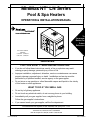
MiniMax NT ® LN Series
Pool & Spa Heaters
OPERATION & INSTALLATION MANUAL
To
Consumer
Retain For
Future
Reference
U.S. Patent Numbers
6,295,980
5,318,007 - 5,228,618
5,201,307 - 4,595,825
WARNING
FOR YOUR SAFETY - READ BEFORE OPERATING
• If you do not follow these instructions exactly, a fire or explosion may result,
causing property damage, personal injury or loss of life.
• Improper installation, adjustment, alteration, service or maintenance can cause
property damage, personal injury or death. Installation and service must be
performed by a qualified installer, service agency or the gas supplier.
• Do not store or use gasoline or other flammable vapors and liquids in the vicinity
of this heater or other appliances.
WHAT TO DO IF YOU SMELL GAS
• Do not try to light any appliance.
• Do not touch any electrical switch; do not use any phone in your building.
• Immediately call your gas supplier from a neighbor's phone.
Follow the gas supplier's instructions.
• If you cannot reach your gas supplier, call the fire department.
For additional free copies of this manual; call (800) 831-7133.
Pentair Water Pool and Spa, Inc.
1620 Hawkins Ave., Sanford, NC 27330 • (919) 566-8000
10951 W. Los Angeles Ave., Moorpark, CA 93021 • (805) 523-2400
Rev. E 4-19-05
P/N 472089
2
Customer Service
If you have questions about ordering Pentair Water Pool and Spa replacement parts,
and pool products, please use the following contact information.
Customer Service (8 A.M. to 5 P.M. Pacific Time)
Phone: (800) 831-7133 (press 3 in voice mail)
Fax: (800) 284-4151
Technical Support for Pentair Water Pool and Spa, Inc.
Sanford, North Carolina (8 A.M. to 5 P.M. Eastern Time)
Phone: (919) 566-8000
Fax: (919) 776-0562
Moorpark, California (8 A.M. to 5 P.M. Pacific Time)
Phone: (805) 523-2400 (Ext. 6502)
Fax: (805) 530-0194
Web site
visit www.pentairpool.com to find information about Pentair Water Pool and Spa, Inc.
© 2005 Pentair Water Pool and Spa, Inc.
1620 Hawkins Ave., Sanford, NC 27330 • (919) 556-8000
10951 West Los Angeles Ave., Moorpark, CA 93021 • (805) 523-2400
All rights reserved. Information in this document is subject to change without notice.
Trademarks and Disclaimers. MiniMax NT LN and the Pentair Pool Products logo are registered trademarks of Pentair
Water Pool and Spa, Inc. Other trademarks and trade names may be used in this document to refer to either the entities
claiming the marks and names or their products. Pentair Water Pool and Spa, Inc. disclaims any proprietary interest in
trademarks and trade names other than its own.
P/N 472089
Rev. E 4-19-05
3
Table of Contents
Section I. Heater Identification Information ...........................................................
4
Section II. Introduction ............................................................................................
5
Important Notices ......................................................................................................................................................................
5
Warranty Information .................................................................................................................................................................
5
Code Requirements ...................................................................................................................................................................
6
Consumer Information and Safety .............................................................................................................................................
6
Section III. Installation ..............................................................................................
7
Specifications ............................................................................................................................................................................
7
Plumbing Connections ...............................................................................................................................................................
8
Valves ........................................................................................................................................................................................
8
Manual By-Pass ........................................................................................................................................................................
8
Below Pool Installation ..............................................................................................................................................................
8
Water Connections .................................................................................................................................................................... 9 - 10
Gas Connections .......................................................................................................................................................................
11
Sediment Traps .........................................................................................................................................................................
11
Gas Pipe Sizing ......................................................................................................................................................................... 12
Testing Gas Pressure/Gas Pressure Requirements .................................................................................................................. 13
Indoor Venting—General Requirements .................................................................................................................................... 14
Indoor (USA) / Outdoor (Canada) Installations ..........................................................................................................................
15
Combustion Air Supply ..............................................................................................................................................................
16
Vent Adaptors ............................................................................................................................................................................ 16
Indoor Installations —Venting Guidelines .................................................................................................................................. 17
Outdoor Installations —Venting Guidelines ............................................................................................................................... 18
Outdoor Vent Kit ........................................................................................................................................................................ 18
Electrical Connections ...............................................................................................................................................................
19
Wiring Diagram—NT LN with DDTC .......................................................................................................................................... 20
Section IV. Operation ................................................................................................ 21
Basic System Operation ............................................................................................................................................................ 21
HSI (Hot-Surface Ignition) Lighting/Operation ...........................................................................................................................
21
Safety Controls .......................................................................................................................................................................... 22 - 23
Digital Display Temperature Controller (DDTC) ......................................................................................................................... 24 - 27
Section V. Troubleshooting ....................................................................................... 28
Troubleshooting (DDTC) ............................................................................................................................................................ 28
Troubleshooting (General) .........................................................................................................................................................
29
Service Checks - Ignition Module .............................................................................................................................................. 29
Section VI. Maintenance ......................................................................................................... 30
Maintenance Instructions ........................................................................................................................................................... 30
Pressure Relief Valve ................................................................................................................................................................ 30
Energy Saving Tips ....................................................................................................................................................................
30
Spring, Fall and Winter Operation .............................................................................................................................................
31
Chemical Balance ...................................................................................................................................................................... 32
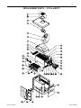
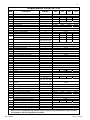
Replacement Parts — NT LNw/DDTC ....................................................................................................................................... 33 - 34
Chauffe-eau pour piscine et spa MiniMax® NT/Guide d'Installation et de Fonctionnement .......................... 36-72
Rev. E 4-19-05
P/N 472089
Section I. Heater Identification Information
4
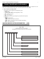
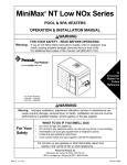
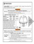
Heater Identification Information
To identify the heater, see rating plate on the inner front panel of the heater. There are two designators for each
heater, one is the Model Number and the other is the Heater Identification Number (HIN).
a. Heater Identification Number (HIN)
The following example simplifies the identification system:
1) HTR : Heater
2) (200, 250, 300 or 400) : Input rating (Btu/hr) X 1000
3) NT : MiniMax NT Series
4) LN : Series Character
5) NH : Gas type (Natural gas) and ignition system (Hot Surface Ignition)
6) Options :
Blank: Standard Model
ASME: ASME Certified (Bronze Headers)
ASHI: ASME Certified Bronze Header and High Altitude Rating
HALT: High Altitude Rating
HEATER IDENTIFICATION INFORMATION — (HIN)
H. I. N.
HEATER IDENTIFICATION NUMBER
ID DESIGNATOR FOR PENTAIR POOL & SPA HEATERS
HTR
400
NT
LN
N H
ASHI
BLANK = STANDARD MODEL
ASME = ASME CERTIFIED
ASHI
= ASME CERTIFIED AND HIGH ALTITUDE RATED
HALT = HIGH ALTITUDE RATED
H = HOT SURFACE IGNITION
N = NATURAL GAS
LN = LOW NOx
NT = MINIMAX NT SERIES
MODEL SIZE = BTU INPUT in 1000 of BTU / HR
P/N 472089
Rev. E 4-19-05
Section II.
Introduction
5
Introduction
MiniMax NT ® LN Series
Pool and Spa Heaters
Congratulations on your purchase of a MiniMax NT LN high performance heating system. Proper installation
and service of your new heating system and correct chemical maintenance of the water will ensure years
enjoyment. The MiniMax NT LN is a compact, lightweight, efficient, induced-draft, gas fired high performance
pool and spa heater that can be directly connected to schedule 40 PVC pipe. The MiniMax NT LN also comes
equipped with the Pentair multifunction temperature controller which shows, at a glance, the proper functioning
of the heater. All MiniMax NT LN heaters are designed with a direct ignition device, HSI (hot-surface ignition),
which eliminates the need for a standing pilot. The MiniMax NT LN requires an external power source
(120/240 VAC 60 Hz) to operate.
This instruction manual provides operating instructions, installation and service information for the
MiniMax NT LN high performance heater. The information in this manual applies to all MiniMax NT LN
models. It is very important that the owner/installer read and understand the section covering installation
instructions, and recognize the local and state codes before installing the MiniMax NT LN. History and
experience has shown that most heater damage is caused by improper installation practices.
IMPORTANT NOTICES
...For the installer and operator of the MiniMax NT LN pool and spa heater. The manufacturer’s warranty may
be void if, for any reason, the heater is improperly installed and/or operated. Be sure to follow the instructions
set forth in this manual. If you need any more information, or if you have any questions regarding to this pool
heater, please contact Pentair Water Pool and Spa, Inc. at (800) 831-7133.
WARRANTY INFORMATION
The MiniMax NT LN pool heater is sold with a limited factory warranty. Specific details are described on the
warranty registration card which is included with the product. Return the warranty registration card after
filling in the serial number from the rating plate inside the heater.
Pentair Water Pool and Spa’s high standards of excellence include a policy of continuous product improvement
resulting in your state-of-the-art heater. We reserve the right to make improvements which change the
specifications of the heater without incurring an obligation to update the current heater equipment.
These heaters are designed for the heating of swimming pools and spas, and should never be used as
space heating boilers, general purpose water heaters, in non-stationary installations, or for the heating
of salt water. The manufacturer’s warranty may be void if, for any reason, the heater is improperly
installed and/or operated. Be sure to follow the instructions set forth in this manual.
CAUTION
OPERATING THIS HEATER CONTINUOUSLY AT WATER TEMPERATURE BELOW 68° F. WILL CAUSE
HARMFUL CONDENSATION AND WILL DAMAGE THE HEATER AND VOID THE WARRANTY. Do not use
the heater to protect pools or spas from freezing if the final maintenance temperature desired is below
68° F., as this will cause condensation related problems.
Rev. E 4-19-05
P/N 472089
Section II.
Introduction
6
CODE REQUIREMENTS
The installation must conform with local codes or, in the absence of local codes, with the National Fuel Gas
Code, ANSI Z223.1/NFPA 54 and/or CSA B149.1, Natural Gas and Propane Installation Codes. The heater,
when installed, must be electrically grounded and bonded in accordance with local codes or, in the absence
of local codes, in the USA, with the National Electrical Code, ANSI/NFPA 7; in Canada, with Canadian
Electric Code, CSA C22.1.
CONSUMER INFORMATION AND SAFETY
WARNING
The U.S. Consumer Product Safety Commission warns that elevated water temperature can be hazardous.
See below for water temperature guidelines before setting temperature.
1. Spa or hot tub water temperatures should never exceed 104° F. A temperature of 100° F. is considered
safe for a healthy adult. Special caution is suggested for young children. Prolonged immersion in hot
water can induce hyperthermia.
2. Drinking of alcoholic beverages before or during spa or hot tub use can cause drowsiness which could
lead to unconsciousness and subsequently result in drowning.
3. Pregnant women beware! Soaking in water above 100° F. can cause fetal damage during the first three
months of pregnancy (resulting in the birth of a brain-damaged or deformed child). Pregnant women
should stick to the 100° F. maximum rule.
4. Before entering the spa or hot tub, the user should check the water temperature with an accurate
thermometer. Spa or hot tub thermostats may err in regulating water temperatures by as much as 4° F.
5. Persons with a medical history of heart disease, circulatory problems, diabetes or blood pressure
problems should obtain their physician's advice before using spas or hot tubs.
6. Persons taking medication which induce drowsiness, such as tranquilizers, antihistamines or
anticoagulants should not use spas or hot tubs.
WARNING
Should overheating occur or the gas supply fail to shut off, turn off the manual gas control valve to the
heater. Do not use this heater if any part has been under water. Immediately call a qualified service
technician to inspect the heater and to replace any part of control system and gas control which has been
under water.
P/N 472089
Rev. E 4-19-05
Section III. Installation
7
Installation Instructions
SPECIFICATIONS
These installation instructions are designed for use by qualified personnel only, trained especially for
installation of this type of heating equipment and related components. Some states require installation and
repair by licensed personnel. If this applies in your state, be sure your contractor bears the appropriate
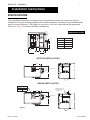
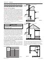
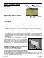
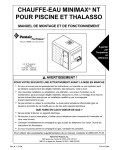
license. See Figure 1 for Outdoor and Indoor Installations.
DIMENSIONS IN INCHES
24.05
Heater
Depth
3.50
MODEL
200
"A" DIM.
21.63
250
24.63
300
27.63
400
34.13
14.50
LEG
8.84
6.64
4.88
"A" DIM.
OUTDOOR INSTALLATION
15.50
7.35
2 in. SOCKET
30.63
24.05
LEG
INDOOR INSTALLATION
INDOOR VENT ADAPTOR
P/N 460506
4 in. Kit
P/N 460507
5 in. Kit
VENT ADAPTOR
(See Indoor Venting
Instructions)
15.50
2.00
7.35
2 in. SOCKET
24.05
30.63
Figure 1.
LEG
Rev. E 4-19-05
P/N 472089
Section III. Installation
8
MANUAL BY-PASS
POOL
HEATER
TO
POOL
CHECK
VALVE
PUMP
FILTER
MANUAL
BY-PASS
GATE
VALVE
Model
CHECK
VALVE
Figure 2.
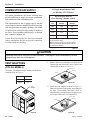
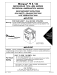
Where the flow rate exceeds the maximum 120 GPM, a
manual bypass should be installed and adjusted. After
adjustments are made, the valve handle should be removed
to avoid tampering. See Figure 2.
FROM
POOL
PLUMBING CONNECTIONS
The MiniMax NT LN heater has the unique capability of
direct schedule 40 PVC plumbing connections. A set of
bulkhead fittings is included with the MiniMax NT LN to
insure conformity with Pentair’s recommended PVC
plumbing procedure. Other plumbing connections can be
used. See Figure 2 for plumbing connections.
CAUTION
Before operating the heater on a new installation, turn
on the circulation pump and bleed all the air from
the filter using the air relief valve on top of the filter.
Water should flow freely through the heater. Do not
operate the heater unless water in the pool/spa is at
the proper level. If a manual by-pass is installed,
temporarily close it to insure that all air is purged
from the heater.
Min. (GPM) Max. (GPM) *
200
20
120
250
30
120
300
30
120
400
40
120
* Do not exceed the maximum recommended
flow rate for the connecting piping.
Table 1.
See page 30 for
Pressure Relief Valve Installations.
BELOW POOL INSTALLATION
If the heater is below water level, the pressure
switch must be adjusted. This adjustment must be
done by a qualified service technician.
See following CAUTION before installation.
CAUTION
VALVES
BELOW OR ABOVE POOL INSTALLATION
When any equipment is located below the surface of the
pool or spa, valves should be placed in the circulation piping
system to isolate the equipment from the pool or spa. Check
valves are recommended to prevent back siphoning.
CAUTION
Exercise care when installing chemical feeders so
as to not allow back siphoning of chemical into the
heater, filters or pump. When chemical feeders are
installed in the circulation of the piping system,
make sure the feeder outlet line is down stream of
the heater, and is equipped with a positive seal
noncorrosive “Check Valve”, (P/N R172288),
between the feeder and heater.
P/N 472089
The water pressure switch is set in the factory at
1½ PSI. This setting is for a heater installed at pool level
or within 3’ above or 3’ below. If the heater is to be installed
more that 3’ above or 3’ below, the water pressure switch
must be adjusted by a qualified service technician. See
page 22, Figure 21.
FLOW SWITCH
If the heater is installed more the 6’ above the pool or
more than 10’ below the pool level, you will be beyond
the limits of the pressure switch and a flow switch must
be installed. Locate and install the flow switch externally
on the outlet piping from the heater, as close as possible
to the heater. Connect the flow switch wires in place of
the water pressure switch wires.
Rev. E 4-19-05
Section III. Installation
9
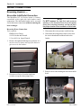
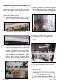
WATER CONNECTIONS
Reversing Headers —
Reversible Inlet/Outlet Connection
The MiniMax NT LN Series heater is factory
assembled with right side inlet/outlet water
connections. The inlet/outlet header can be reversed
for left side water connections without removing the
heat exchanger.
Reversing Water Connections
Tools required:
Phillips Screw Driver
9/16 in. Socket and Wrench
1/2 in. & 9/16 in. Open Wrench
NOTE
Do NOT remove the high-limit and pressure
switches or the thermistor from the front header
during the reversing procedure, as they will be in
the proper location when installed on the left side.
3. Disconnect the water pressure switch wiring.
4. Disconnect the temperature sensor wires from
the circuit board and feed them back to the
header.
1. Remove the right and left large access doors. It is
not necessary to remove the top of the heater to
gain access to the headers.
2. Disconnect all wires from the high-limit
switches except the short jumper wire.
Rev. E 4-19-05
5. Remove the 8 bolts holding the main inlet/outlet
head.
P/N 472089
Section III. Installation
10
Reversible Inlet/Outlet Connection, cont’d.
On the MiniMax NT LN Series heater there is insulation
installed by the factory on the return head side of the
heaters. This insulation is there so that if the heads are
reversed in the field, during initial installation of the
heater, the high limits will be insulated from the heat
radiating from the flue collector.
6. Return head in position before removal. This view
shows the insulation installed by the factory.
Remove the 8 bolts holding the return head in place.
9. Install the temperature sensing probe by passing
the wires through the hole provided on the left
side of the brace panel. Route wires through the
support bracket.
7. When heads are removed, replace the heat
exchanger tube seal gaskets.
10. Reconnect all the high limit wires and the
pressure switch wiring, routing the wires
through the same hole as the thermostat sensor
wires.
8. Exchange the inlet/outlet header with the return
header. Lift the insulation to allow the main head
to be installed. Align header with the heat
exchanger. When head is placed into position,
release the insulation; it will now shield the high
limits from the heat produced by the flue collector.
Install header bolts, and tighten snugly by hand.
(This will help avoid cross threading.) When
tightening, use a cross pattern starting from the
center of the header. DO NOT over tighten.
11. Pump and bleed system to check the head for
leaks.
12. Reinstall the two large inspection plates on the
appropriate side.
Remember: The inlet and outlet markings
on the header are still correct.
Do not plumb the heater backwards.
P/N 472089
Rev. E 4-19-05
Section III. Installation
11
GAS CONNECTIONS
GAS LINE INSTALLATIONS
Before installing the gas line, be sure to check which gas the heater has been designed to burn. This is important because different types of gas require different gas pipe sizes. The rating plate on the heater will indicate
which gas the heater is designed to burn. The tables, shown on page 12, show which size pipe is required for
the distance from the gas meter to the heater. The table is for natural gas at a specific gravity of .65.
When sizing gas lines, calculate three (3) additional feet of straight pipe for every elbow used. When installing
the gas line, avoid getting dirt, grease or other foreign material in the pipe as this may cause damage to the gas
valve, which may result in heater failure.
The gas meter should be checked to make sure that it will supply enough gas to the heater and any other
appliances that may be used on the same meter. The gas line from the meter will usually be of a larger size than
the gas valve supplied with the heater. Therefore a reduction of the connecting gas pipe will be necessary.
Make this reduction as close to the heater as possible.
The heater and any other gas appliances must be disconnected from the gas supply piping system during any
pressure testing on that system, (greater that ½ PSI). The heater and its gas connection must be leak tested
before placing the heater in operation. Do not use flame to test the gas line. Use soapy water or another
nonflammable method.
NOTE
A manual main shut-off valve must be installed externally to the heater.
WARNING
DO NOT INSTALL THE GAS LINE UNION INSIDE THE HEATER CABINET. THIS WILL VOID YOUR WARRANTY.
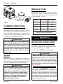
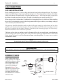
SEDIMENT TRAPS
Install a sediment in front of
the gas controls. The sediment
trap shall be either a tee fitting
with a capped nipple in the
bottom outlet which can be
removed for cleaning, as
illustrated in Figure 3, or a
other device recognized as an
effective sediment trap. All
gas piping should be tested
after installation in accordance
with local codes.
GAS
VALVE
GAS
SUPPLY
UNION
TEE
FITTING
MANUAL
SHUT OFF
VALVE
3 INCHES
MINIMUM
NIPPLE
HEATER CABINET
CAP
Figure 3.
Rev. E 4-19-05
P/N 472089
Section III. Installation
12
GAS PIPE SIZING
Table 2.
PIPE SIZING FOR GAS LINE CONNECTIONS
MAXIMUM EQUIVALENT PIPE LENGTH (Ft.)
Natural Gas at 1000 B.T.U. per Cubic Foot
1/2”
3/4”
1”
1-1/4” 1-1/2”
2”
2-1/2”
MODEL
NAT
NAT
NAT
NAT
NAT
NAT
NAT
200
-
30’
125’
450’
-
-
-
250
-
20’
70’
250’
600’
-
-
300
-
10’
50’
200’
400’
-
-
400
-
-
20’
100’
200’
400’
-
“RESIDENTIAL” NATURAL GAS 2 STAGE REGULATION
In many Natural gas line installations, the gas supplier and/or installer may utilize a two stage regulation
process where by at the streets main gas supply they will install the first stage gas regulator, which would
be at a higher pressure. This higher pressure is usually set at 2 psi or 5 psi and can be for long distances
and in a much smaller pipe size. Then within a short distance of the pool heater, generally around
24 inches, they will install a second regulator, which is the second stage. This second stage regulator
would be set at the minimum operating pressure for the heater. For “Natural Gas Pentair Pool Heaters”
the minimum is 7 inches W.C.
See “Gas Pressure Requirement Charts”
Stage One "High Pressure" Gas Pipe Sizing
Stage Two "Low Pressure" Gas Pipe Sizing
2 PSI @ 1000 B.T.U. Per CU. FT.
Stage 2 set at 7 in. W.C.
MAXIMUM EQUIVALENT PIPE LENGTH
MAXIMUM EQUIVALENT PIPE LENGTH
Model
0 to 50 Ft.
50 to 100 Ft.
100 to 150 Ft.
Model
0 to 10 Ft.
10 to 20 Ft.
200 through 300
1/2 in.
1/2 in.
1/2 in.
200 through 300
3/4 in.
3/4 in.
400
3/4 in.
3/4 in.
3/4 in.
400
3/4 in.
1 in.
5 PSI @ 1000 B.T.U. Per CU. FT.
200 through 400
1/2 in.
1/2 in.
Stage 2 set at 7 in. W.C.
1/2 in.
Table 3.
P/N 472089
200 through 400
3/4 in.
1 in.
Table 4.
Rev. E 4-19-05
Section III. Installation
13
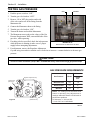
TESTING GAS PRESSURE
Inlet
Manifold
1. Push the power switch to “OFF”.
2. Turn the gas valve knob to “OFF”.
3. Remove 1/8 in. NPT plug on the outlet side
of the valve and screw in the fitting from the
Manometer kit.
4. Connect the Manometer hose to the fitting.
5. Turn the gas valve knob to “ON”.
6. Turn on the heater and read the Manometer.
7. The Manometer must read per the values of the Gas
Pressure Requirement Table, on manifold side of the
gas valve, while operating.
8. If reading is below specified; check the inlet pressure
MiniMax NT LN
while the heater is running to make sure of proper
Illustration above is for Natural Gas, see Table 5.
supply before attempting adjustments.
9. For adjustment, remove the Regulator Adjustment
Cap and using a screwdriver turn the screw clockwise to increase - counterclockwise to decrease gas
pressure.
CAUTION
The use of Flexible Connectors (FLEX) is NOT recommended as they cause excessive high gas pressure drops.
GAS PRESSURE REQUIREMENTS
Natural
Regulator Adjustment Cap
1/8" NPT Plug
(Inlet Press)
ON
OFF
Figure 4.
1/8" NPT Plug
(Manifold Press)
Gas Pressure
Model
Inches
W.C.
Maximum Inlet
LN
10
Minimum Inlet
LN
5*
Manifold
LN
4
NOTE: Al l r e a d i n g s mu s t b e t a ke n wh i l e
h e a t e r i s o p e ra t i n g . Any a d j u s t me n t s o r
readings made while heater is off will result in
performance problems.
All Values are +/- 0.2 inch W.C.
* 6 inch. W.C. for LN 400 Model.
Table 5.
Rev. E 4-19-05
P/N 472089
Section III. Installation
14
INDOOR VENTING — General Requirements
The vent pipe must be the same size or larger. The MiniMax NT LN heaters are capable of a 360-degree discharge
rotation and operate with a positive vent static pressure and with a vent gas temperature less than 400° F. The total length
of the horizontal run must not exceed the length that is listed below in the tables.
NOTE
The allowable vent runs for each vent pipe diameter are different and can not be exceeded.
Each 90-degree elbow reduces the maximum horizontal vent run by 8 feet and each 45-degree elbow in
the vent run reduces the maximum vent run by 4 feet. See the tables below for the maximum vent
lengths using 90-degree and 45-degree elbows.
The MiniMax NT LN is a “Category III” appliance and is an induced-draft pool and spa
heater which uses positive pressure to push flue gases through the vent pipe to the outside.
This requires a completely sealed vent system—single wall vent pipe with sealed-seams
and joints. Flue gases under positive pressure may escape into the dwelling with any
cracks or loose joints in the vent pipe, or improper vent installation. The vent pipe must
be of a sealed-seam construction, such as those listed for use with “Category III Appliances”,
and for operating temperatures less than 400° F. The use of listed thimbles, roof jacks and/
or side vent terminals are required; and the proper clearances to combustible materials
must be maintained in accordance with type of vent pipe employed—in the absence of a
clearance recommendation by the vent pipe manufacturer, the requirements of the Uniform
Mechanical Code should be met. The ventilation air requirements for the MiniMax NT
heater can be found on page 16. It is recommended that vent
runs over 18 feet be insulated to reduce condensation related
5 inch Vent Pipe
problems and/or the use of a condensate trap in the vent run
close to the heater may be necessary in certain installations
Number of
Maximum
such as cold climates. The MiniMax NT LN heater is suitable
Elbows
Vent Run
for through-the-wall venting, see table and dimensions below.
(Feet)
Recommended sources for Side-wall vent hood terminals
include: The Field Controls Co. (2308 Airport Road, Kingston,
NC 28501, (800)742-8368) and Tjernlund Products Inc. (1601
Ninth Street, White Bear Lake, MN 55110, (800) 255-4208)—
consult manufacturer for model information and availability.
CAUTION
Do NOT combine exhaust vent pipes to a common exhaust
vent in multiple unit installations. Run separate vent pipes.
90°
45°
0
1
1
1
1
2
2
2
—
1
2
3
—
1
45
45
41
37
33
37
33
4 inch Vent Pipe
Number of
Elbows
90°
45°
Maximum
Vent Run
(Feet)
1
1
1
2
—
1
2
—
22
18
14
14
Table 6.
5 inch Vent Pipe
Number of
Elbows
90°
45°
Maximum
Vent Run
(Feet)
2
2
2
3
3
3
4
2
3
4
—
1
2
—
29
25
21
29
25
21
21
Table 7.
C
THROUGH WALL VENT KITS FOR HEATERS
Part
Number
Dim. A
Dim. B
Dim. C
471532 4 in. Dia. 6 in. Dia.
8½ in.
471543 5 in. Dia. 8 in. Dia.
8½ in.
Table 8.
P/N 472089
Dim. D
Dim. E
Dim. F
B
F
A
E
6 5/16 in. 12 5/8 in. 10 5/8 in.
8 in.
12 5/8 in. 10 5/8 in.
D
Figure 5.
Rev. E 4-19-05
Section III. Installation
15
INDOOR INSTALLATION (USA ONLY)
OUTDOOR SHELTER INSTALLATION (CANADA)
Chimney or Gas Vent
Vent Cap and
Riser Furnished
by Installer
See page 16 for Vent Adaptors
All products of combustion and vent gases must be
completely removed to the outside atmosphere through a
vent pipe which is connected to the stack adaptor. A vent
pipe extension of the same size must be connected to the
vent adaptor and extended at least 2 feet higher than highest
point of the roof within a 10 foot horizontal radius, and at
least 3 ft. higher than the point at which it passes through
the roof, or as permitted by local code; see Figures 6, 7
and 12. The vent should terminate with an approved vent
cap (weather cap) for protection against rain or blockage
by snow. Insulated vent pipe and an approved roof jack
shall be employed through the roof penetration.
Outlet Air
Opening
Optional
Side
Wall Vent
Inlet Air
Opening
Heater
Figure 6.
The heater must be located as close as practical to a
chimney or gas vent.
Chimney or Gas Vent
Vent Cap and
Riser Furnished
by Installer
CAUTION
The heater should be installed at least 5 feet away
from the pool or spa.
The heater must be placed in a suitable room with adequate
ventilation and on a leveled floor, where leakage from heat
exchanger or water connections will not result in damage
to the area adjacent to the heater or the structure. When
such locations cannot be avoided, it is recommended that
a suitable drain pan with adequate drainage, be installed
under the heater. The pan must not restrict air flow.
It is recommended to install the heater on fire-resistance
slabs. Do not install the heater directly on a combustible
wood floor without placing a non-combustible material
between the floor and the heater. Heaters must NEVER
be installed directly on carpeting.
Installations in basements, garages, or underground
structures where flammable liquids may be stored must
have the heater elevated 18 inches from the floor. The
following minimum clearances from combustible materials
must be provided.
Outlet Air Opening
Optional
Side
Wall Vent
Inlet Air Opening
Heater
Figure 7.
The heater should not be installed closer than 6 inches to
any fences, walls or shrubs at any side or back, nor
closer than 18 inches at the plumbing side. A minimum
clearance of 24 inches must be maintained at the front of
the heater.
6"
INSTALLATION
INDOOR
(Outrdoor Shelter)
OUTDOOR
INCHES
INCHES
WATER PIPING
18
18
BLANK
6
6
REAR
6
6
TOP *
18
Open Un-roofed Area
FRONT
24
24
* To ceiling or roof.
Rev. E 4-19-05
24"
DOOR
SIDE
OF
HEATER
6"
18"
Table 9.
Figure 8.
P/N 472089
Section III. Installation
16
COMBUSTION AIR SUPPLY
Air Supply Requirements Guide
for MiniMax NT LN Heaters
For indoor installation, the heater location must
provide sufficient air supply for proper combustion
and ventilation of the surrounding area.
Net Free open Area for
Each Opening * (Square Inches)
The requirements for the air supply specify that the
room in which a heater is installed should be provided
with two permanent air supply openings; one within
12 inches of the ceiling, the other within 12 inches of
the floor. These openings shall directly, or through
duct, connect to outdoor air.
Pentair Water Pool and Spa, Inc. does not recommend
indoor installations that do not provide combustion
air from outside the building.
Heater
Size
Ducted from
Outside
Direct from
Outside
200
100
50
250
125
63
300
150
75
400
200
100
* Area indicated is for one of two openings; one at floor
level and one at the ceiling.
NOTE: If using louvered type or screen type openings,
check with Louver/Screen Manufacturers to correct for
the Louver/Screen resistance.
Table 10.
CAUTION
Chemicals should not be stored near the heater installation. Combustion air can be contaminated by corrosive
chemical fumes which can void the warranty.
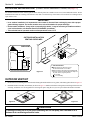
1. Remove the six (6) retaining screws from the old
exhaust grill and discard the screws, gasket, and
exhaust grill as shown in Figure 10.
VENT ADAPTORS
(FITS ALL MODELS)
The proper vent adaptor must be installed on the heater
as shown below in Figure 9.
Product No.
Vent Dia.
460506
4 in.
460507
5 in.
EXHAUST GRILL
SCREWS (6)
GASKET
Figure 10.
Vent
Adaptor
2. Install the Vent Adaptor as shown in Figure 11.
Make sure the holes in the gasket, metal flange of
the main vent assembly, and heater cover are
aligned before securing into place using the six (6)
screws provided in the Vent Adaptor Kit.
METAL FLANGE
SCREWS (6)
GASKET
Figure 9.
P/N 472089
Figure 11.
Rev. E 4-19-05
Rev. E 4-19-05
Roof
Jack
Roof
Thimble
3 ft. min.
Chimney/Gas Vent
2 ft. min.
Vent Cap
may use a single wall vent pipe with
permanently sealed seams, joints and
proper insulating materials.
must be suitable for use with category III
appliances with flue gas temperature ratings
less than 400 deg. F.
must be the same diameter as the
vent connector.
Vent pipe extension:
must terminate with an approved (listed)
roof jack, storm collar, and vent/weather cap.
must use a roof thimble through the
roof penetration.
must extend at least 3 ft. higher than the
point at which it passes through the roof,
or as permitted by local code.
Vent for roof penetration installations:
Ridge
More Than10 ft.
vent terminated at least 24"
above any object within 10 ft.
7'
Force Air Inlet
4'
.
1' min
3'
Vent Hood
1' min.
above grade
Recommended sources for
side wall Vent Hood;
see "Section Venting".
Vent Hood
4'
.
1' min
Clearances indicated are for non-mechanical air supply inlet to the building.
For mechanical air supply inlet, a minimum horizontal clearance of 10 feet
should be maintained away from the vent termination.
Air Supply
Figure 12.
must be located the following distances away from any door, window, or gravity air inlet:
4 ft. below
4 ft. horizontally
1 ft. above
must be not less than 7 ft. above public walkways.
must be at least 3 ft. above any outside air intake located within a 10 ft. radius.
must NOT be within 3 ft. of an inside corner of the structure.
must be at least 1 ft. above grade.
Vent termination for side wall installations:
Walkway
Vent Hood
4'
INDOOR INSTALLATIONS
MINIMAX NT VENTING GUIDELINES
Section III. Installation
17
P/N 472089
Section III. Installation
18
OUTDOOR INSTALLATION
(Outdoor Shelter Installation in Canada, see page 15)
For outdoor installation with an exhaust grill, the heater must be placed in a suitable area on a level, noncombustible surface. Do not
install the heater under an overhang with clearances less than 3 feet from the top of the heater. The area under an overhang must be
open on three sides.
IMPORTANT!
• In an outdoor installation it is important to ensure water is diverted from overhanging eves with a proper
gutter/drainage system. The heater must be set on a level foundation for proper drainage.
• Under certain conditions, “heavy rains or unusually high winds”, it may be necessary to install an outdoors
vent. In this situation, use Outdoor Vent Kit, P/N 460424, (see below).
• This unit shall not be operated outdoors at temperatures below -20o F.
OUTDOOR INSTALLATION
VENTING GUIDELINES
4'
3'
SIDE VIEW
4'
Property Line
4 ft.
4'
Window
4 ft.
Force
Air Inlet
Exhaust Grill
(Vent)
s
de
co ts.
g
n
n
i
e
ild
bu uirem
al
oc k req
l
k
ec ac
Ch setb
for
Building
Vent Termination:
Heater
Must be at least 3 ft. above any forced
air inlet located within a 10 ft. radius.
(side view)
Figure 13.
Must be located 4 feet away from the building wall
openings, and at the following distances away from
any door, window, or gravity air inlet:
4 ft. below,
4 ft. horizontally
OUTDOOR VENT KIT
1.
Remove the six (6) retaining screws from the old exhaust grill and discard the screws, gasket, and exhaust grill as shown in Figure 14.
2.
Install the Outdoor Vent Kit, (P/N 460424), as shown in Figure 15. Make sure the holes in the gasket, metal flange of the main vent
assembly, and heater cover are aligned before securing into place using the six (6) screws provided in the Outdoor Vent Kit.
EXHAUST GRILL
METAL FLANGE
SCREWS (6)
GASKET
GASKET
SCREWS (6)
Figure 15.
Figure 14.
CAUTION
If installing the heater next to or near an air conditioning unit or a heat pump, allow a minimum of 36 in.
between the air conditioning unit and the heater.
P/N 472089
Rev. E 4-19-05
Section III. Installation
19
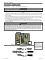
ELECTRICAL CONNECTIONS
Electrical Rating
60 Hz
120 / 240 Volts AC, single phase
CAUTION
This heater is designed to operate at 120 or 240 VAC. It is not recommended to be connected to OR operate on a 208 VAC.
NOTE
• The MiniMax NT LN heater is prewired for 240-volt AC connection using the “RED” connector and the “BEIGE” common
connector; see below, Figure 16. For 120-volt AC supply, remove the “BEIGE” common connector and plug it into the “BLUE”
common connector.
• When connecting the power supply to the “Line Terminal Block” inside the junction box, follow the polarity as shown below.
Connecting to 120 VAC, make sure that you connect the wire to the terminal (L), the neutral wire is connected to the neutral
terminal (N) and the ground is connected to the ground terminal (GND); see below, Figure 17.
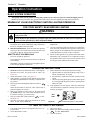
• If any of the original wiring supplied with this heater must be replaced, installer must supply (No. 18 AWG, 600V, 105° C.
U.L. approved AWM low energy stranded) copper wire or it’s equivalent. Thermal fuse wiring must be replaced with 18 AWG,
600V, 150° C. temp. rating.
CAUTION
The installation must conform with local codes or, in the absence of local codes, with the National Fuel Gas Code,
ANSI Z223.1/NFPA 54 and/or CSA B149.1, Natural Gas and Propane Installation Codes. If an external electrical
source is utilized, the heater, when installed, must be electrically grounded and bonded in accordance with local
codes or, in the absence of local codes, in the USA, with the National Electrical Code, ANSI/NFPA 7; in Canada, with
Canadian Electric Code, CSA C22.1.
Always use crimp type connectors when connecting two wires.
TRANSFORMER
CONNECTOR
BLUE
120V CONNECTOR
BEIGE
COMMON CONNECTOR
TERMINAL BLOCK
FOR AC INPUT
120 / 240 VOLT SINGLE
PHASE "See Below"
RED
240V CONNECTOR
Figure 16.
LINE TERMINAL BLOCK
INTERNAL
FACTORY WIRES
GREEN WIRE
GROUND
CONNECTION
WHITE WIRE
NEUTRAL / WHITE 120 VAC
LINE #1 FOR 240 VAC
You need to open the right
door then remove the
control panel cover for
servicing the Line Terminal
Block as shown in Figures
16 & 17, (see item 40 in the
exploded view on page 33).
N
BLACK WIRE
L
HOT / BLACK 120 VAC
LINE #2 FOR 240 VAC
Figure 17.
Rev. E 4-19-05
P/N 472089
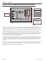
BLOWER
AIR PRESSURE SW.
J5 J8 J6 J1 J2
GY
24VAC
SPA
COM
POOL
J4
24V
P4
W
PR
Y
J7
TFUSE
HLMT
PRESS
P7
JI0
VLV
P10
R
W
BL
O
R
W
GY
O
PR
BL
BK
Y
W
BR
J17
BK
BK
GY
PS
TH
24VAC
VLV
GND
F1
F2
FC
9
GY
GY
8
7
6
5
Y
BK
GY
9 W
8
7
6
5
4
3
2
1
IGN/120
L1
IGN/240
L2
IGN/FS
IGNITER
9
8
7
6
5
4
3
2
1
P12(240V)
4
3
2
1
J16
W
W
BK
BK
GY
BK
BK
W
BK
BK
BK
BL
GY
P12(120V)
W
W
L'INSTALLATION ELECTRIQUE DU FUSIBLE THERMIQUE DOIT ETRE REMPLACEE
AVEC UNE ECHELLE DE TEMPERATURE A 18 AWG, 600V, 150 DEGRES CELSIUS.
18 AWG, 600V, 150˚C TEMP. RATING.
SI L'INSTALLATION ELECTRIQUE ORIGINALE D'USINE DOIT ETRE REMPLACEE,
L'INSTLLATEUR DOIT PROCURER DES CABLES UL/CSA APPROUVES AVEC
18 AWG, 600V, 105 DEGRES CELSIUS D'ECHELLE DE TEMPERATURE.
BR
BR
BK
R
Y
BK/W
R/W
BK
BR
PR
O
J12
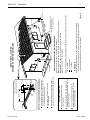
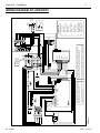
NOTE :
THE HEATER
IS PREWIRED
FOR 240 VAC
THERMAL FUSE WIRING MUST BE REPLACED WITH
J9
MV
MV
G
THERMAL FUSE
Y
Y
GAS VALVE
J11
IGN
MOD
P9
P11
W
R
IF ORIGINAL FACTORY WIRING MUST BE REPLACED,
INSTALLER MUST SUPPLY UL/CSA APPROVED WIRE
WITH 18 AWG, 600V, 105˚C TEMP. RATING.
DDTC
FAN
Figure 18.
REMOTE CONTROL
MANUAL FOR
& INSTALLATION
PR
O
WATER PRESS
SWITCH
SEE OPERATION
G
PR
{
O
BK
BK
150˚F
R
R
THERMISTER
472088B
O
BK/W
BK/W
GY
R/W
R/W
COM NO
R
R
J15 P15
O
115˚F
HIGH LIMITS
PR
PR
R
R
Y
Y
P/N 472089
PR
BK
BK
W
BK
W
Y
6 6
5 5
4 4
3 3
2 2
BLOWER
J14
P14
W
BK
BK
BK
W
W
W
W
P13
1 1
J13
BK
O
W
PR
O
BK
Y
W
MiniMax NT LN W/DDTC Wiring Diagram
BK
BK
L
N
G
: BLUE (BLEU)
: BROWN (MARRON)
BR
: RED (ROUGE)
: YELLOW (JAUNE)
: WHITE (BLANC)
: RED W/WHITE TRACE
(ROUGE ET/BLANC)
PR
R
Y
W
R/W
OR
240 VAC
120 VAC
BK/W : BLACK W/WHITE TRACE
(NOIR ET/BLANC)
: ORANGE (ORANG)
: PURPLE (VIOLET)
O
: GRAY (GRIS)
GY
: GREEN (VERT)
: BLACK (NOIR)
BL
(COULEUR DU CABLE)
WIRE COLOR
ATTACH
GROUND
WIRE HERE
BK
G
BK
W
BOND LOG
(ON THE SIDE JACKET)
W
G
W
TERM
BLOCK
G
Section III. Installation
20
WIRING DIAGRAM–NT LN/W DDTC
Rev. E 4-19-05
Section IV. Operation
21
Operation Instruction
BASIC SYSTEM OPERATION
1.
Start pump, make sure the pump is running and is primed, to close the water pressure switch and supply power to
heater. Be sure the pool and/or spa is properly filled with water. Follow the Lighting/Operating instructions below.
MINIMAX NT LN HSI ELECTRONIC IGNITION LIGHTING/OPERATION
FOR YOUR SAFETY: READ BEFORE LIGHTING
WARNING
If you do not follow these instructions exactly, a fire or explosion may result causing property damage, personal
injury or loss of life.
Do not attempt to light the heater if you suspect a gas leak. Lighting the heater can result in a fire or explosion
which can cause personal injury, death, and property damage.
A. This appliance does not have a pilot. It is equipped with
an ignition device which automatically lights the burners.
Do not try to light the burners by hand.
B. BEFORE OPERATING, smell all around the appliance
area for gas. Be sure to smell next to the floor because some
gas is heavier than air and will settle on the floor.
-
WHAT TO DO IF YOU SMELL GAS
D. Do not use this appliance if any part has been under water.
Immediately call a qualified service technician to inspect
the appliance and to replace any part of the control system
and any gas control which has been under water.
-
Do not try to light any appliance.
Do not touch any electrical switch; do not use any phone in
your building.
Immediately call your gas supplier from a neighbor's phone.
Follow the gas supplier's instructions.
If you cannot reach your gas supplier, call the Fire
Department.
C. Use only your hand to push in or turn the gas control knob.
Never use tools. If the knob will not push in or turn by hand,
don't try to repair it, call a qualified service technician. Forced
or attempted repair may result in a fire or explosion.
OPERATING INSTRUCTIONS
1.
2.
3.
4.
5.
6.
7.
8.
STOP! Read the safety information above, (A through D).
Open the access doors. Set power switch to ”OFF”, (see
Figure 25).
Set the thermostat to ”OFF”, (see page 27).
This appliance is equipped with an ignition device which
automatically lights the burners. Do not try to light the burners by hand.
Push in gas control knob slightly and turn clockwise
to “OFF”.
NOTE: Knob cannot be turned to “OFF” unless knob is
pushed in slightly. Do not force.
Wait five (5) minutes to clear out any gas. If you then smell
gas, STOP! Follow "B" in the safety information above.
If you don't smell gas, go to the next step.
Turn gas control knob counterclockwise
to “ON”.
See Figure 19.
Close the access doors and set the thermostat to desired
Mode: “POOL, SPA or REMOTE”.
9.
Set the thermostat to the desired temperature setting.
a. Ignition module is energized and the pre-purge cycle is
started, approximately 15 seconds.
b. Fan motor starts, which closes Vacuum Air Pressure (fan)
switch.
c. Check for powering-up the (glow coil) hot-surface ignitor
by viewing through the glass window or opening on the
burner face plate.
10. If the appliance will not operate, follow the instructions
"To Turn Off Gas To Appliance" and call your service technician or gas supplier.
Gas
Inlet
ON
OFF
Figure 19.
Gas control knob shown in “ON” position.
TO TURN OFF GAS TO APPLIANCE
1.
2.
Turn off all electric power to the appliance if service is to
be performed.
Set the thermostat to “OFF”.
3.
4.
5.
Rev. E 4-19-05
Open access doors.
Push in gas control knob slightly and turn clockwise
to "OFF". Do not force.
Close access doors.
P/N 472089
Section IV. Operation
22
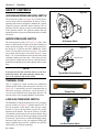
SAFETY CONTROLS
Figure 20.
VACUUM AIR PRESSURE (FAN) SWITCH
The air pressure switch, (see Figure 20), is a safety device
used to insure that the combustion air blower (fan) is
operating and has been designed to monitor the vacuum
(negative) pressure within the blower housing. The air
pressures switch is factory set and is connected upstream
of the ignition module. The ignition module does not
operate unless the air pressure switch and all safety switches
are closed.
WATER PRESSURE SWITCH
The water pressure switch, (see Figure 21), closes when
there is a sufficient flow of water to the heat exchanger to
safely operate the heater. The switch has been preset by
the Factory at 1½ PSI for operation. NOTE: See, Below
Pool Level Installation instructions on page 8. The switch
may remain closed with no water flow if there is more
than a 3 ft. elevation difference between the heater (heat
exchanger) and the pool water line—if this is the case, the
water pressure switch must be reset by a qualified service
technician to maintain open switch contacts with no water
flow.
AIR PRESSURE SWITCH
Air Pressure Switch
Figure 21.
Adjustment Knob
NOTE
If the pool is more than one floor above or one floor
below the heater, the water pressure switch may
have to be replaced with a flow switch.
Typical Water Pressure Switch
THERMAL FUSE
This is a single-use switch, mounted on combustion
chamber jacket divider (inner front panel). The fuse, (see
Figure 22), is activated by excessive temperature due to
abnormal operating conditions. Upon detection of
excessive heat within the inner front panel, the fuse will
open the safety circuit causing shutdown of the heater.
Figure 22.
Thermal Fuse
Figure 23.
LOW GAS PRESSURE SWITCH
The MiniMax NT LN model heater uses a low gas supply
pressure switch, (see Figure 23), ahead of the gas valve, to
prevent operation of the heater when the gas supply
pressure is below the minimum required for proper
operation of the burners. The switch is factory set. In the
event that the switch does not close and prevents the firing
of the heater, the cause of the low gas supply pressure must
be corrected. Typical causes are undersized supply piping,
undersized gas meter or low gas regulator setting (gas
supply regulator and gas meter problems are typically
corrected by your local gas company).
P/N 472089
Low Gas Pressure Switch
Rev. E 4-19-05
Section IV. Operation
SAFETY CONTROLS, (cont’d.)
23
Flame Current
Check Point
HIGH LIMITS
A “High Limit”, is a safety device that opens the electrical
circuit and shuts off the heater based on a water temperature
set point within the “High Limit Device”. The MiniMax NT
LN series of heaters contains two (2) high limit devices which
are located on the main inlet / outlet header, one sensing the
inlet water temperature and one sensing the outlet water
temperature.
Diagnostic LED
1 Flash - Air Flow Fault
2 Flashes - Flame no Call for Heat
3 Flashes - Lock Out
OPERATION OF IGNITION MODULE
Figure 24.
The Ignition Module, (see Figure 24), is microprocessor based
and operates on 24 VAC supplied by the transformer. The
control utilizes a microprocessor to continually and safely monitor, analyze, and control the proper operation of the gas
burners. The module with the presence of the flame sensor, using flame rectification, allows the heater to operate.
1. HEAT MODE
• When a call for heat is received from the thermostat supplying 24 volts to the (TH) terminal, the module will check
the pressure switch for normally open contact. The combustion blower is then energized and, once the air pressure
switch contacts close, the 15-second "pre-purge" period begins. After pre-purge, the hot surface igniter is energized
for approximately 40-second heat-up period, followed by the gas valve for the "trial for ignition" (TFI) period, for
maximum of 7 seconds for the LN model.
• When the flame is detected during the TFI period, through the flame sensor, the igniter is deactivated and the gas
valve remains energized.
Note: After the pre-purge period the combustion blower slows down to half normal speed during the heat-up and TFI
periods and continues thereafter for another 30 seconds at low speed, then return to full speed for the remainder of
the heating cycle.
• The thermostat, air pressure switch and burner flame are constantly monitored to assure that the system operates
properly. When the thermostat is satisfied and the demand for heat ends, the gas valve is immediately de-energized,
the module senses the loss of flame signal and initiates the 45-second "post-purge" period before de-energizing the
combustion blower.
2. FAILURE TO LIGHT THE BURNER—LOCK OUT
Should the main burner fail to light, or the flame is not detected during the
first TFI (try for ignition) cycle, the gas valve is de-energized and the ignition
module performs an "inter-purge" delay (approximately 15 seconds) before
attempting another TFI cycle. The module will attempt 2 additional TFI's
cycles before locking out. The gas valve will be turned off immediately. The
combustion blower will be turned off following 45 seconds "post-purge"
period.
The module will automatically reset after one hour, if the thermostat
is still calling for heat, and attempt a new TFI cycle.
3. FLAME FAILURE—RE-IGNITION
INTERNAL POWER SWITCH
Figure 25.
If the established flame signal is lost while the burner is operating, the control
will respond within .08 second. The gas valve is de-energized and the control
starts a new ignition sequence in an attempt to relight the burner. The ignition attempt will be repeated (3) times. If the
burner does not relight, the control will go into lockout as previously described in the “Failure to Light the Burner—Lock
Out”. If flame is reestablished, normal operation resumes.
Rev. E 4-19-05
P/N 472089
Section IV. Operation
24
DIGITAL DISPLAY TEMPERATURE CONTROLLER (DDTC)
REMOTE BUTTON
POWER
REMOTE
PRESSURE SW
POOL
SPA
SYSTEM
INDICATOR
LIGHTS
THERMOSTAT
POOL BUTTON
SPA BUTTON
OFF
HEATING
SERVICE
TEMPERATURE SETTING
POOL
OFF BUTTON
SPA
TEMP. UP
PRESS ANY ARROW ONCE TO
CHECK SET TEMPERATURE
Figure 26.
SPA AND POOL
TEMPERATURE
SET BUTTONS
TEMP. DOWN
The DDTC board, shown in Figure 26, is a digital temperature controller capable of controlling the pool, spa
or both to a minimum temperature of 65° F. (below 65° F. display reads "Off") and a maximum of 104° F.
The DDTC board also functions as a system status indicator, using LED lights and programmed error codes.
During normal operation, the DDTC will display the current temperature of the water returning to the
heater, depending on which mode has been selected, “Pool” or “Spa”. This is accomplished by a thermister
(sensor) on the inlet port of the water header of the heater and working in conjunction with the internal
microprocessor controlling the operation of the heater.
Changing the desired pool or spa temperature is easily done by simply depressing the appropriate up or
down arrow until the display reads the desired set-point temperature. For example, set pool to 78° F. and the
spa to 104° F., when releasing the up or down arrow the display will flash once then return to the current
temperature.
At any time, you wish to know the temperature setting of the pool or spa, simply press the appropriate up or
down arrow, the display will flash once and display the set-point temperature for three (3) seconds, then
flash once again and return to the current temperature.
P/N 472089
Rev. E 4-19-05
Section IV. Operation
25
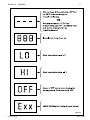
Figure 27.
Rev. E 4-19-05
P/N 472089
Section IV. Operation
26
SET UP
The MiniMax NT LN Heater comes from the factory preset with a pool temperature setting of 78° F. and a
preset spa temperature of 100° F., and in the off mode setting. Once the power is turned on, the DDTC
board will do a self diagnostic internal check, during this time the display will first read “888”, then the
display will switch to three dashes “- - -“, this process takes approximately ten (10) seconds. The DDTC
will then illuminate the “Power” LED and “Off” LED, see Figure 27.
1. Turn on the power to the heater; the switch is on the bottom of the electrical junction box located internally on the right side of the cabinet. The DDTC will now go through the self-diagnostic’s test as stated
above.
2. Turn on the circulating system pump and make sure that adequate water is being delivered to the heater,
The “PRESSURE SW” LED will now illuminate.
3. If you are using the heater with a remote control system, open the right door of the heater to access the
rear portion of the DDTC. Locate the three terminals marked “Pool” (J5), “Spa” (J6) and “Com” (J8).
If the remote system is a three-wire remote unit, connect the pool lead to the “pool” terminal J5, connect
the spa lead to the “spa” J6 terminal and connect the common wire to the “com” terminal J8. If the
remote system is a two-wire remote, the remote system will be used to turn the heater on for a selected
body of water, Pool or Spa, select which application you are working with and connect one wire to the
common terminal J8 and the other wire to either “Pool J5” or “Spa J6”. Close and latch the door.
LED INDICATORS
There are nine lights that can be seen from the front of the control panel, (five are system indicators and four
are mode indicators), which helps you understand the operation of the heater, see Figure 26. If something
should go wrong, the lights will aid in troubleshooting the problem. An additional four lights can be seen
after opening the control panel. These four lights are diagnostic indicators for the service technician to
troubleshoot the system.
On the right front of the DDTC board there are four Buttons and corresponding LED lights, see Figure 26.
Using the buttons allows you to select one of the four modes and the lights indicate which operational mode
that the heater is in, Off, Spa mode, Pool mode or Remote mode. If the heater is not connected to a remote
system then the remote mode will not be used.
The following are descriptions of the five system indicators:
• POWER
The light is on at all times, in any switch position, indicating 24 VAC power is being supplied to the control
circuit. If it fails to light, no other light will be on. Possible causes are:
1. External power to the heater is disconnected; check service panel circuit breaker or fuses;
2. Transformer has failed.
• PRESSURE SW (WATER PRESSURE SWITCH)
This light is on when Spa/Pool Selector switch is on, indicates the circulating pump is running properly.
If pressure light fails to light, the pump may have lost its prime or water flow may be restricted by an
inadvertently closed valve or clogged filter or pump basket. If you have determined that there is no water
flow restriction to the heater, you should call a qualified technician.
• THERMOSTAT
This light is on when the thermostat contacts close, signaled by the water temperature falling below the
set-point, calling for the heater to fire to maintain the desired water temperature.
P/N 472089
Rev. E 4-19-05
Section IV. Operation
27
• HEATING
The heating light is on any time the thermostat has signaled a call for heat which initializes the ignition
safety circuit — the light comes on indicating successful firing of the main burners and stays on until the
pool/spa reach the water temperature setting.
• SERVICE
The service light is off during normal operation of heater. The light only comes on if a problem with a
control has occurred or when the heater is first firing. The problem must be investigated by the technician
prior to attempts to fire the heater again.
TEMPERATURE SETTING
The heater comes factory set at 78° F. for the pool mode and 100° F. for the spa mode, using the up and
down arrows, you can set the thermostats to a minimum temperature of 65° F., or a maximum of 104° F.
If you desire to heat only one body of water, the thermostat is capable of an off mode. As an example, if you
only wish to heat the spa and not the pool, simple depress and hold the pool down arrow, and the thermostat
will lower its setting to 65° F. then go to an off mode. If there is a remote system connected to the heater,
please see the special thermostat setting features under Heating Mode Selection & Remote mode.
HEATING MODE SELECTION
1. Off Mode: The heater will not come on. NOTE: The "Off" display on the Digital Display Temperature
Controller does not mean that the heater is off. It only states that the pool or spa thermostat has been
turned off.
2. Spa Mode: The heater will operate and heat the spa to the desired temperature.
3. Pool Mode: The heater will operate and heat the pool to the desired temperature.
4. Remote Mode: The DDTC is compatible with two and three wire remote control systems. In order to
operate by a remote control system, the REMOTE mode must be selected on the front panel. When the
REMOTE mode is selected, the REMOTE LED will light up.
REMOTE CONTROL
THE TWO-WIRE REMOTE CONTROL SYSTEM is typically installed and connected to the heater for spa
heating. The two-wire remote system is usually provided with a water temperature sensor that monitors the
system temperature and turns the heater on or off in response to the temperature of the spa. To heat a spa, it
should be connected to terminals J6 and J8. Pool heating remote control would require connecting to
terminals J5 and J8. If the REMOTE mode is set at the front panel LED light, the DDTC will respond to a
contact closure by remote system and heater will operate until the remote system temperature setting is
satisfied.
NOTE: With this type of two-wire remote, with its own temperature sensors and system control, using the
up arrows on the front of the DDTC, hold down the up arrow until you reach the maximum setting of
104° F., this allows the remote system thermostat to operate the heater at any set-point below 104° F., the
heater thermostats then act as a secondary controller if water temperature reaches 104° F.
THE THREE-WIRE REMOTE CONTROL SYSTEM will be connected to terminals J5, J6 & J8. J8 is the
common terminal. If the heater is in the REMOTE mode, the DDTC will monitor the terminals and respond
to a contact closure between J5 & J8 or J6 & J8. A contact closure between J5 & J8 will cause the DDTC to
switch to the POOL setting and control the heater to the DDTC pool set-point temperature. A contact
closure between J6 & J8 will cause the DDTC to switch to the SPA setting and control the heater to the
DDTC spa set-point temperature. If only heating the spa, then depress the pool down arrow until the display
goes to “Off”.
Rev. E 4-19-05
P/N 472089
Section V.
Troubleshooting
28
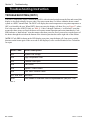
Troubleshooting Instruction
TROUBLESHOOTING (DDTC)
The DDTC temperature display contains three LED’s with a decimal point between the first and second, this
display is also used to display an error code if for some reason there is a failure within the heater control
system or a DDTC internal fault. The DDTC will display the actual temperature or set-point temperature or
OFF, as selected by the user. When DDTC detects an error, the display will show Exx, see Figure 27, where
Exx is the error code of DDTC fault, see Table 11. Codes 1 through 9 indicate a “soft lockout” error that
means after these errors are fixed, the heater will resume normal operation and restart immediately. Code
ERR indicates a “hard lockout” error that means after these errors are fixed, you need to reset the power of
the heater through the switch on the bottom of the electrical junction box on the right side of the cabinet.
NOTE: If Code ERR is shown on the LED display at any time, turn the heater off, (from power switch),
then turn on the heater again. If the error code is still displayed, call a certified Pentair Service Technician
for repair.
Error Code
Error Description
E01
System Low Voltage
E02
High Temperature Limit
E03
Thermal Fuse Open
E04
Fan Failure
E05
Ignition / Flame Failure
E06
Gas Valve / Module Failure
E07, E08, E09
Not Used
ERR
Call Pentair's Technical Service Department at: (800) 831-7133
Table 11.
P/N 472089
Rev. E 4-19-05
Section V.
Troubleshooting
29
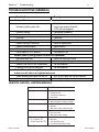
TROUBLESHOOTING (GENERAL)
Possible Cause
Heater will not come on
Remedy
Check if electrical connections are
Automatic ignition system fails
correct and securely fastened –
If YES, call serviceperson.
Pump not running
Place pump in operation
Pump air locked
Check for leaks
Filter dirty
Clean filter
Pump strainer clogged
Clean strainer
Defective wiring or connection
Repair or replace wires
Defective pressure switch
Replace switch
Defective gas controls
Call serviceperson
On-Off switch in "OFF" position
Turn switch to "ON"
Heater Short Cycling (Rapid On and Off Operation)
Insufficient water flow
Clean filter and pump strainer
Defective wiring
Repair or replace wiring
Defective flow valve or out of adjustment
Call serviceperson
Defective hi-limit and/or thermostat
Call serviceperson
Heater Makes Knocking Noises,
make sure all valves on system are open.
Heater operating after pump has shut off
Shut off gas supply and call serviceperson
Heater exchanger scaled
Shut off gas supply and call serviceperson
SERVICE CHECKS—IGNITION MODULE
Symptom
1. Dead
2.
3.
4.
5.
Rev. E 4-19-05
Cause/Cure
A.
B.
C.
D.
Thermostat on—no ignition A.
B.
Valve on, no ignition
A.
B.
C.
Ignitor on, no valve action A.
B.
C.
Flame okay during
A.
Try For Ignition (TFI),
B.
no flame sense (after TFI) C.
D.
Miswired
Transformer bad
Fuse/Circuit breaker bad
Bad control
Miswired
Bad thermostat no voltage at terminal
Defective ignitor
Miswired
Bad control (check voltage at ignitor)
Valve coil open
Open valve wire
Bad control (check voltage)
Bad flame sensor
Bad wires
Poor ground at burner
Poor flame (check flame current)
P/N 472089
Section VI. Maintenance
30
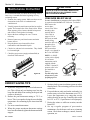
Maintenance Instruction
It is recommended that you check the following items at
least every six months and at the beginning of every
swimming season.
1. Examine the venting system. Make sure there are no
obstructions in the flow of combustion and
ventilation air.
2. Visually inspect the main burner and the hot surface
ignitor. The normal color of the flame is blue. When
flame appears yellow, burners should be inspected
and cleaned. Check ignitor for damage.
3. Inspect the heat exchanger for soot. Clean as
necessary.
4. Remove burner tray and clean burners and main
burner orifices.
5. Keep the heater area clean and free from
combustibles and flammable liquids.
6. Check wire ends and wire connections. They should
be clean and tight.
7. Check the gas pressure (supply and manifold) as
described in this manual.
Figure 28.
LN
LOW-NOx
ENERGY SAVING TIPS
1. If possible, keep pool or spa covered when not in
use. This will not only cut heating costs, but also
keep dirt and debris from settling in the pool and
conserve chemicals.
2. Reduce the pool thermostat setting to 78° F. or
lower. This is accepted as being the most healthy
temperature for swimming by the American Red
Cross.
3. Use an accurate thermometer.
4. When the proper maximum thermostat settings
have been determined, tighten the thermostat knob
stopper.
P/N 472089
CAUTION
REMOVE THE FLOW VALVE ASSEMBLY WHEN DRILLING
THE HOLE TO INSTALL A PRV, OTHERWISE, YOU WILL
DRILL INTO THE VALVE ASSEMBLY.
PRESSURE RELIEF VALVE
In some installations, a pressure relief valve (PRV)
is required on the MiniMax NT LN Series. To install a
PRV, remove the
RELIEF
access doors,
VALVE
remove Flow Valve
assembly, then
FOR PRV
carefully drill a
INSTALLATION
DRILL THRU
3/8 in. hole in
THE NPT PORT
center of 3/4 in.
NPT port (on main
header) being
REMOVE FLOW VALVE
careful to drill only
BEFORE DRILLING
through wall at
THE NPT PORT
bottom of 3/4 in.
NPT port and no
Figure 29.
deeper—now thread in
the 3/4 in. NPT PRV.
RELIEF VALVE
NOTE: (A.S.M.E.
version varies slightly.
It is of bronze
construction, and is
supplied with the
A.S.M.E. Section IV,
pressure relief valve
pre-installed at
factory.)
Test the relief valve
at least once a year
by lifting up lever.
TO WINTERIZE,
OPEN DRAIN VALVE
A.S.M.E. VERSION
A.S.M.E. VERSION
5. Set time clock to start circulation system no earlier
than daybreak. The swimming pool loses less heat
at this time.
6. For pools that are only used on the weekends, it is
not necessary to leave the thermostat set at 78° F.
Lower the temperature to a range that can be
achieved easily in one day. Generally, this would
be 10° F. to 15° F., if pool heater is sized properly.
7. During the winter or while on vacation, turn the
heater off.
8. Set up a regular program of preventative
maintenance for the heater each new swimming
season. Check heat exchanger, controls, burners,
operation, etc.
Rev. E 4-19-05
Section VI. Maintenance
31
SPRING AND FALL OPERATION
If the pool is being used occasionally, do not turn the heater completely off. Set the thermostat down to
65° F. This will keep the pool and the surrounding ground warm enough to bring the pool up to a
comfortable swimming temperature in a shorter period of time.
WINTER OPERATION
CAUTION
• Operating this heater continuously at water temperatures below 68° F. will cause harmful condensation and will
damage the heater and void the warranty.
• If the heater has been drained for freezing condition, do NOT turn "ON" until the system is circulating water.
• Water trapped in the heat exchanger can result in freeze damage to the exchanger or headers. Freeze damage is
specifically not covered by the warranty.
If the pool won't be used for a month or more, turn the heater off at the main gas valve. For areas where
there is no danger of water freezing, water should circulate through the heater all year long, even though you are
not heating your swimming pool. The MiniMax NT LN should not be operated outdoors at temperatures
below 0° F. for propane and -20° F. for natural gas. Where freezing is possible, it is necessary to drain
the water from the heater. This may be done by opening the drain valve, located at the inlet/outlet header,
(see Figure 29), allowing all water to drain out of the heater. It would be a good practice to use compressed
air to blow the water out of the heat exchanger. (See additional notes under Important Notices in
Introduction.)
Rev. E 4-19-05
P/N 472089
Section VI. Maintenance
32
CHEMICAL BALANCE
RULE: 7.4 to 7.6 is a desirable pH range. It is essential
to maintain correct pH, see Table 13.
POOL AND SPA WATER
If pH becomes too high (over alkaline), it
has these effects:
Your Pentair Pool Products pool heater was designed
specifically for your spa or pool and will give you many
years of trouble-free service, provided you keep your
water chemistry in proper condition.
Three major items that can cause problems with your
pool heater are: improper pH, disinfectant residual, and
total alkalinity. These items, if not kept properly
balanced, can shorten the life of the heater and cause
permanent damage.
CAUTION
Heat exchanger damage resulting from chemical
imbalance is not covered by the warranty.
WHAT A DISINFECTANT DOES
Two pool guests you do not want are algae and bacteria.
To get rid of them and make pool water sanitary for
swimming - as well as to improve the water's taste, odor
and clarity - some sort of disinfectant must be used.
Chlorine and bromine are universally approved by health
authorities and are accepted disinfecting agents for
bacteria control.
WHAT IS A DISINFECTANT
RESIDUAL?
When you add chlorine or bromine to the pool water, a
portion of the disinfectant will be consumed in the
process of destroying bacteria, algae and other oxidizable
materials. The disinfectant remaining is called chlorine
residual or bromine residual. You can determine the
disinfectant residual of your pool water with a reliable test
kit, available from your local pool supply store.
You must maintain a disinfectant residual level adequate
enough to assure a continuous kill of bacteria or virus
introduced into pool water by swimmers, through the air,
from dust, rain or other sources.
It is wise to test pool water regularly. Never allow
chlorine residual to drop below 0.6 ppm (parts per
million). The minimum level for effective chlorine or
bromine residual is 1.4 ppm.
pH - The term pH refers to the acid/alkaline balance of
water expressed on a numerical scale from 0 to 14. A test
kit for measuring pH balance of your pool water is
available from your local pool supply store; see Table 12.
pH Chart
Table 12.
Strongly Acid
0
1
2
3
Neutral
4
5
6
7
8
9
Strongly Alkaline
10
11
12
13
Muriatic Acid has a pH of about 0. Pure water is 7
(neutral). Weak Lye solution have a pH of 13-14.
P/N 472089
14
1. Greatly lowers the ability of chlorine to destroy
bacteria and algae.
2. Water becomes cloudy.
3. There is more danger of scale formation on the
plaster or in the heat exchanger tubing.
4. Filter elements may become blocked.
If pH is too low (over acid) the following
conditions may occur:
1. Excessive eye burn or skin irritation.
2. Etching of the plaster.
3. Corrosion of metal fixtures in the filtration and
recirculation system, which may create brown, blue,
green, or sometimes almost black stains on the
plaster.
4. Corrosion of copper tubes in the heater, which may
cause leaks.
5. If you have a sand and gravel filter, the alum used as
a filter aid may dissolve and pass through the filter.
CAUTION: Do not test for pH when the chlorine
residual is 3.0 ppm or higher, or bromine residual
is 6.0 ppm or higher. See your local pool supply
store for help in properly balancing your water
chemistry.
RULE: Chemicals that are acid lower pH. Chemicals
that are alkaline raise pH.
pH Control Chart
Table 13.
6.8
7.0
7.2
Add Soda, Ash or
Marginal
Sodium Bicarbonate
7.4 7.6
7.8
8.0
Ideal
Marginal
8.2
8.4
Add Acid
ALKALINITY High or Low:
"Total alkalinity" is a measurement of the total amount
of alkaline chemicals in the water, and control pH to a
great degree. (It is not the same as pH which refers
merely to the relative alkalinity/acidity balance.) Your
pool water's total alkalinity should be 100 - 140 ppm to
permit easier pH control.
A total alkalinity test is simple to perform with a reliable
test kit. You will need to test about once a week and
make proper adjustments until alkalinity is in the proper
range. Then, test only once every month or so to be sure
it is being maintained. See your local pool dealer for
help in properly balancing the water chemistry.
Rev. E 4-19-05
33
REPLACEMENT PARTS — NT LN w/DDTC
Rev. E 4-19-05
P/N 472089
34
\
$]^_
<
$
;
!"#
%
%
&'
=>>?@?BJ!
K>?@!"#
%?'>Q
X?'>Q
&%!"#
?'>Q?@
?'>Q?@
%YY?'>Q
<
$
;
<
$
;
!"
?BJ!!B\&]
?BJ!!B;\&]
X^'
=>_^"B?@!"#
=>_`>?@!"#
=>_%!^"B?@
=>_%!^"B?@
_BK>Q@
@%@K>Q
@%@{
&>"^
&|!"#
!>&|
|B}
%>#!"#
=Q>
^'
^"B
`>Y@
`>Y@_Y';B;;;~
_Y';B;;;~
%>
<
$
;
'>JY
'>KQ
'^"B
>'>%!"#
^';B;;;~
`@=Q>>>
!>!"#
KQ!"#>
KQ!"#>
JY!"#
!BYYZ}^>[
>Y!;|Z}^>[
X?>!"#Z}^>[
=>@|>@Z^Q][
}
}
}
}
<
Z;;;;;;;[
<
<
Z;;;;;;;[
<
Z;;;;;;;[
$;
$;
$
;
$
;
;;
;;
;
$$
;<
<
$
<
$<
$
$
<<
$
;
;;<
$;
;;
<$
<
$
$$
;
$
;
;;$
;
;
;
;
$
$
;<
$
;;
;;
;;
$<
;;
$<
<
<
$;;
;
<;
<
;;
<
$<
;
;
;;Z{[`;;Z{[
<
"#"$%+;<=$+;>
$
J;
$[
P/N 472089
Rev. E 4-19-05
35
NOTES
Rev. E 4-19-05
P/N 472089
40
36
SAVE THESE INSTRUCTIONS
Pentair Water Pool and Spa, Inc.
1620 Hawkins Ave., Sanford, NC 27330 • (919) 566-8000
10951 W. Los Angeles Ave., Moorpark, CA 93021 • (805) 523-2400
P/N 472089
Rev. E 4-19-05