1
11 1
MiniMax® NT Series
POOL & SPA HEATERS
SERVICE MANUAL
WARNING
FOR YOUR SAFETY - READ BEFORE OPERATING
Warning: If you do not follow these instructions exactly, a fire or explosion may
result, causing property damage, personal injury or loss of life.
For additional free copies of this manual; call (800) 831-7133.
WARNING
Warning: Improper installation, adjustment, alteration, service or maintenance can
cause property damage, personal injury or death. Installation and service must be
performed by a licensed qualified installer, service agency or the gas supplier.
WHAT TO DO IF YOU SMELL GAS
For Your
Safety
Do not try to light any appliance.
Do not touch any electrical switch; do not use any phone in your building.
Immediately call your gas supplier from a neighbor's phone.
Follow the gas supplier's instructions.
If you cannot reach your gas supplier, call the fire department.
•
•
•
•
Do not store or use gasoline or other flammable vapors and
liquids in the vicinity of this or other appliances.
Pentair Pool Products, Inc.
1620 Hawkins Ave., Sanford, NC 27330 • (919) 774-4151
10951 W. Los Angeles Ave., Moorpark, CA 93021 • (805) 523-2400
Rev. B 2-11-04
P/N
NTSM03
2
Table of Contents
Introduction .............................................................................................................................
3
Important Notice ..........................................................................................................................................................................
Code Requirements .....................................................................................................................................................................
Safety Rules ................................................................................................................................................................................
3
3
4
Installation Tips ........................................................................................................................
Dimensions ...............................................................................................................................
4
5
Installation Outdoors/Indoors .................................................................................................
6
Installation on Floors Constructed of Combustible Materials .......................................................................................................
6
Gas Requirements ...................................................................................................................
7-8
Gas Line Installations ..................................................................................................................................................................
Sediment Traps ...........................................................................................................................................................................
Pipe Sizing for Gas Line Installations ..........................................................................................................................................
Residential Propane 2 Stage Regulation .....................................................................................................................................
Residential natural Gas 2 Stage Regulation ................................................................................................................................
7
7
8
8
8
Testing Gas Pressure ..............................................................................................................
9
Gas Pressure Requirements .......................................................................................................................................................
9
Water Connections................................................................................................................... 10-11
Plumbing Connections .................................................................................................................................................................
Manual By-Pass ..........................................................................................................................................................................
Valves ..........................................................................................................................................................................................
Below Pool Installation ................................................................................................................................................................
Pressure Switch Adjustment ........................................................................................................................................................
10
10
11
11
11
Reversing Headers ................................................................................................................... 12-13
Air Requirements ..................................................................................................................... 14-17
Venting — Indoor Installations ..................................................................................................................................................... 14 - 16
Venting — Outdoor Installations .................................................................................................................................................. 17
Electrical Wiring ....................................................................................................................... 18-21
Wiring Schematic for all Dual Voltage Blowers ............................................................................................................................
Wiring Diagram ............................................................................................................................................................................
Schematic for Remote Controls (2 and 3 Wire) ...........................................................................................................................
19
20
21
Basic System Operation .......................................................................................................... 22-24
Heater Operation — Firing Sequence — Ignition Failure — Hard Lock Out ................................................................................
Starting Operation — HSI Electronic Ignition Lighting/Operation .................................................................................................
Chemical Balance ........................................................................................................................................................................
22
23
24
Maintenance ............................................................................................................................. 25-28
Pressure Relief Valve ..................................................................................................................................................................
Spring and Fall Operation — Winter Operation ...........................................................................................................................
Burner Tray Removal ...................................................................................................................................................................
Desooting ....................................................................................................................................................................................
Reinstalling Heat Exchanger .......................................................................................................................................................
25
25
26
27
28
Troubleshooting ....................................................................................................................... 29-46
Glossary .................................................................................................................................... 47
MiniMax NT (Standard) Parts List & Exploded View (Dual Voltage) ........................................... 48-49
MiniMax NT Low NOx Parts List & Exploded View (Dual Voltage) ............................................ 50-51
Warranty Information ...............................................................................................................
P/N NTSM03
Back Cover
Rev. B 2-11-04
3
Important Notice
MiniMax® NT Series
Pool and Spa Heaters
....For the installer and operator of the MiniMax NT Series pool and spa heaters. The manufacturer’s
warranty may be void if, for any reason, the heater is improperly installed and/or operated. Be sure to follow
the instructions set forth in this manual. If you need any more information, or if you have any questions
regarding to this pool heater, please contact Pentair Pool Products, Inc. at (800) 831-7133.
These heaters are designed for the heating of swimming pools and spas, and should never be
employed for use as space heating boilers, general purpose water heaters, in non-stationary
installations, or for the heating of salt water.
CAUTION
OPERATING THIS HEATER CONTINUOUSLY AT WATER TEMPERATURE BELOW 68° F. WILL CAUSE
HARMFUL CONDENSATION AND WILL DAMAGE THE HEATER AND WILL VOID THE WARRANTY.
Do not use the heater to protect pools or spas from freezing if the final maintenance temperature desired is
below 68° F. as this will cause condensation related problems.
CODE REQUIREMENTS
The installation must conform with local codes or, in the absence of local codes, with the National Fuel Gas
Code, ANSI Z223.1/NFPA 54 and/or CSA B149.1, Natural Gas and Propane Installation Codes. If an
external electrical source is utilized, the heater, when installed, must be electrically grounded and bonded in
accordance with local codes or, in the absence of local codes, in the USA, with the National Electrical
Code, ANSI/NFPA 7; in Canada, with Canadian Electric Code, CSA C22.1-98.
Rev. B 2-11-04
P/N
NTSM03
4
Safety Rules
1. Spa or hot tub water temperatures should never exceed
104° F. A temperature of 100° F. is considered safe for
a healthy adult. Special caution is suggested for young
children.
4. Before entering the spa or hot tub, the user should
check the water temperature with an accurate
thermometer. Spa or hot tub thermostats may err in
regulating water temperatures by as much as 4° F.
2. Drinking of alcoholic beverages before or during spa
or hot tub use can cause drowsiness which could lead
to unconsciousness and subsequently result in
drowning.
5. Persons with a medical history of heart disease,
circulatory problems, diabetes or blood pressure
problems should obtain their physician's advice before
using spas or hot tubs.
3. Pregnant women beware! Soaking in water above 100°
F. can cause fetal damage during the first three months
of pregnancy (resulting in the birth of a brain-damaged
or deformed child). Pregnant women should stick to
the 100° F. maximum rule.
6. Persons taking medication which induce drowsiness,
such as tranquilizers, antihistamines or anticoagulants
should not use spas or hot tubs.
WARNING
Should overheating occur or the gas supply fail to shut off, turn off the manual gas control valve to the heater.
Do not use this heater if any part has been under water. Immediately call a qualified service technician to
inspect the heater and to replace any part of control system and gas control which has been under water.
Installation Tips
CAUTION
DO NOT INSTALL HEATER
UNDER ANY ROOF
OVERHANG NOT HAVING A
PROPER RAIN GUTTER.
DO NOT PLACE GAS
SUPPLY LINE UNION
COUPLING INSIDE OF
HEATER JACKET.
(Follow Recommendations of
National Fuel Gas Code NFPA 54.)
DO NOT RESTRICT
ACCESS TO HEATER
WITH PIPING.
P/N NTSM03
CAUTION
DO NOT INSTALL the heater under an overhang
of less than three (3) feet from the top of the heater.
The area under the overhang must be open on three
sides. Overhangs must be such that flue products
are not diverted into living spaces. Heaters installed
under overhangs must be protected from direct roof
water drainage by gutters and the like.
DO NOT INSTALL the heater in locations which
will permit the accumulation of leaves or other
combustible material on or around the base of the
heater.
DO NOT INSTALL the heater in a location that
will allow sprinklers to operate near the heater
equipment since the water may cause damage to the
controls and/or electronics.
Rev. B 2-11-04
5
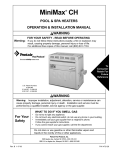
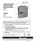
Dimensions
OUTDOOR VENTILATION
15.50
7.35
2 in. SOCKET
24.05
30.63
LEG
14.50
"A" DIM.
21.63
250
24.63
300
27.63
400
34.13
4.88
8.84
LEG
MODEL
200
"A" DIM.
DIMENSIONS IN INCHES
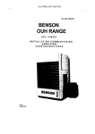
INDOOR VENTILATION
15.50
INDOOR VENT ADAPTOR
P/N 460506
4 in. Kit
P/N 460507
5 in. Kit
7.35
2.00
2 in. SOCKET
24.05
30.63
LEG
14.50
LEG
8.84
4.88
MODEL
200
"A" DIM.
21.63
250
24.63
300
27.63
400
34.13
"A" DIM.
Rev. B 2-11-04
P/N
NTSM03
6
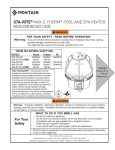
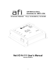
Installation - Outdoors/Indoors
The heater should not be installed closer than 6 inches to any
fences, walls or shrubs at any side or back, nor closer than 18
inches at the plumbing side. A minimum clearance of 24 inches
must be maintained at the front of the heater. The heater should
be installed at least 5 feet away from the pool or spa.
IMPORTANT!
Under certain conditions, “heavy rains or unusually high winds”,
it may be necessary to install an outdoors vent. In this situation,
use vent adaptor P/N 460507 and outdoor vent P/N 471357.
NOTE
From the point where the flue products leave the heater, that point
MUST be a minimum of (4) feet below, and (4) feet horizontally from
or (1) foot above any door, window or gravity inlet to a building.
6"
DOOR
24"
6"
OUTDOOR INSTALLATION
VENTING GUIDELINES
3'
um )
nim tal
Mi on e
4' oriz ranc
(H lea
C
4' Min. Below
4'
18"
Figure 3.
Figure 1.
INDOOR INSTALLATIONS
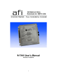
INSTALLATION ON FLOORS CONSTRUCTED
OF COMBUSTIBLE MATERIALS
The heater must be placed in a suitable room on a non-combustible
floor or on a non-combustible base and in an area where leakage
from heat exchanger or water connections will not result in
damage to the area adjacent to the heater or the structure. When
such locations cannot be avoided, it is recommended that a
suitable drain pan with adequate drainage, be installed under the
heater. The pan must not restrict air flow.
Installations in basements, garages, or underground structures
where flammable liquids may be stored must have the heater
elevated 18 inches from the floor using a non-combustible base.
The following minimum clearances from combustible materials
must be provided.
The heater may be placed on a “combustible floor”
using the method listed below:
a) The heater must be installed on a non-combustible floor
and at least six inches from any combustible material or
wall. Construct a non-combustible base from masonry
blocks as illustrated in Figure 2.
BASE FOR USE ON COMBUSTIBLE FLOORS
Water Connection
6"
Remaining
.
in
M
6"
M
in
.
Ceiling Clearance
Side
Front
Back
Top
18 in.
24 in.
-
-
6 in.
-
6 in.
-
-
-
-
18 in.*
*To ceiling or roof.
CAUTION
SHEET METAL
BLOCKS
HOLLOW MASONARY BLOCKS, NOT LESS THAN 4" THICK
(LAID WITH ENDS UNSEALED AND JOINTS MATCHED
FOR AIR CIRCULATION). COVER BLOCKS WITH
24 GA. (MIN.) GALVANIZED SHEET METAL.
Figure 2.
P/N NTSM03
Chemicals should not be stored near the heater installation.
Combustion air can be contaminated by corrosive chemical
fumes which can void the warranty.
Rev. B 2-11-04
7
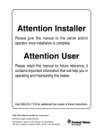
Gas Requirements
GAS LINE INSTALLATIONS
CAUTION
Before installing the gas line, be sure to check which
gas the heater has been designed to burn. This is
important because different types of gas require
different gas pipe sizes. The rating plate on the heater
will indicate which gas the heater is designed to burn.
Tables 1-5, shown on page 8, shows which size pipe
is required for the distance from the gas meter to the
heater. The table is for natural gas at a specific gravity
of .65 and propane at a specific gravity of 1.5.
When sizing gas lines, calculate three (3) additional
feet of straight pipe for every elbow used.
When installing the gas line, avoid getting dirt, grease
or other foreign material in the pipe as this may cause
damage to the gas valve, which may result in heater
failure.
The gas meter should be checked to make sure that it
will supply enough gas to the heater and any other
appliances that may be used on the same meter.
The gas line from the meter will usually be of a larger
size than the gas valve supplied with the heater.
Therefore a reduction of the connecting gas pipe will
be necessary. Make this reduction as close to the
heater as possible.
The heater and any other gas appliances must be
disconnected from the gas supply piping system
during any pressure testing on that system, (greater
than ½ PSIG).
The heater and its gas connection must be leak
tested before placing the heater in operation. Do not
use flame to test the gas line. Use soapy water or
another nonflammable method.
A manual main shut-off valve must be installed
externally to the heater. See Figure 4.
SEDIMENT TRAPS
Install a sediment in front of the gas controls.
The sediment trap shall be either a tee fitting with
a capped nipple in the bottom outlet which can be
removed for cleaning, as illustrated below, or a
other device recognized as an effective sediment
trap. All gas piping should be tested after installation
in accordance with local codes. See Figure 4.
WARNING
Do not install the gas line union inside the heater
cabinet. This will void your warranty.
GAS
VALVE
GAS
SUPPLY
UNION
TEE
FITTING
MANUAL
SHUT OFF
VALVE
NIPPLE
3 INCHES
MINIMUM
HEATER CABINET
CAP
Figure 4.
Rev. B 2-11-04
P/N
NTSM03
8
Installation (Gas Line)
Pipe Sized For Length Of Run In Equivalent Feet
Table 1.
PIPE SIZING FOR GAS LINE CONNECTIONS
MAXIMUM EQUIVALENT PIPE LENGTH
Natural gas at 1000 B.T.U. per Cubic Foot
Propane Gas at 2500 B.T.U. per Cubic Foot
1/2”
MODEL
3/4”
1”
1-1/4”
1-1/2”
2”
2-1/2”
NAT PRO NAT PRO NAT PRO NAT PRO NAT PRO NAT PRO NAT PRO
200
-
20’
30’
80’
125’ 250’
450’
600’
-
-
-
-
-
-
250
-
10’
20’
50’
70’
150’ 250’
500’
600’
-
-
-
-
-
300
-
-
10’
30’
50’
100’ 200’
350’
400’
600’
-
-
-
-
400
-
-
-
10’
20’
60’
150’ 200’
450’
400’
-
-
-
100’
“RESIDENTIAL” PROPANE 2 STAGE REGULATION
In many Propane gas line installations, the gas supplier and/or installer will utilize a two stage regulation process
where by at the supply tank they will install the first stage gas regulator, which would be at a higher pressure, usually
10 psi. This higher pressure allows for a much longer distance and in a much smaller pipe size. Then within a short
distance of the pool heater, usually around 24 inches, they will install a second regulator, which is the second stage,
and this would be set at the required inlet pressure of the heater.
See “Gas Pressure Requirement Charts”
Stage One "High Pressure" Gas Pipe Sizing
Stage Two "Low Pressure" Gas Pipe Sizing
10 PSI @ 2500 B.T.U. Per CU. FT.
Stage 2 set at 14 in. W.C.
MAXIMUM EQUIVALENT PIPE LENGTH
MAXIMUM EQUIVALENT PIPE LENGTH
Model
0 to 50 Ft.
50 to 100 Ft.
100 to 150 Ft.
Model
0 to 10 Ft.
10 to 20 Ft.
75 through 400
1/2 in.
1/2 in.
1/2 in.
75 through 400
3/4 in.
3/4 in.
Table 2.
Table 3.
“RESIDENTIAL” NATURAL GAS 2 STAGE REGULATION
In many Natural gas line installations, the gas supplier and/or installer may utilize a two stage regulation process
where by at the streets main gas supply they will install the first stage gas regulator, which would be at a higher
pressure. This higher pressure is usually set at 2 psi or 5 psi and can be for long distances and in a much smaller pipe
size. Then within a short distance of the pool heater, generally around 24 inches, they will install a second regulator,
which is the second stage. This second stage regulator would be set at the minimum operating pressure for the heater.
For “Natural Gas Pentair Pool Heaters” the minimum is 7 inches W.C.
See “Gas Pressure Requirement Charts”
Stage One "High Pressure" Gas Pipe Sizing
Stage Two "Low Pressure" Gas Pipe Sizing
2 PSI @ 1000 B.T.U. Per CU. FT.
Stage 2 set at 7 in. W.C.
MAXIMUM EQUIVALENT PIPE LENGTH
MAXIMUM EQUIVALENT PIPE LENGTH
Model
0 to 50 Ft.
50 to 100 Ft.
100 to 150 Ft.
Model
75 through 300
1/2 in.
1/2 in.
1/2 in.
350 & 400
3/4 in.
3/4 in.
3/4 in.
5 PSI @ 1000 B.T.U. Per CU. FT.
75 through 400
1/2 in.
1/2 in.
10 to 20 Ft.
75 through 300
3/4 in.
3/4 in.
350 & 400
3/4 in.
1 in.
Stage 2 set at 7 in. W.C.
1/2 in.
Table 4.
P/N NTSM03
0 to 10 Ft.
75 through 400
3/4 in.
1 in.
Table 5.
Rev. B 2-11-04
9
Testing Gas Pressure
Inlet
1. Push the power switch to “OFF”.
2. Turn the gas valve knob to “OFF”.
3. Remove 1/8 in. NPT plug on the
outlet side of the valve and screw in
the fitting from the Manometer kit.
4. Connect the Manometer hose to the
fitting.
5. Turn the gas valve knob to “ON”.
6. Turn on the heater and read the
Manometer.
7. The Manometer must read
4 in. W.C. for natural gas or
11 in. W.C. for propane, on
manifold side of the gas valve,
while operating.
8. If reading is below specified; check
the inlet pressure while the heater is
running to make sure of proper
supply before attempting adjustments.
9. For adjustment, remove the Regulator
Adjustment Cap and using a screwdriver
turn the screw clockwise to increase counterclockwise to decrease gas pressure.
CAUTION
The use of Flexible Connectors (FLEX) is NOT
recommended as they cause excessive high gas
pressure drops.
Manifold
GAS PRESSURE REQUIREMENTS*
Natural
Maximum inlet gas pressure 10 in. WC
Minimum inlet gas pressure **5 in. WC
Normal manifold pressure
4 in. WC
Propane
14 in. WC
12 in. WC
11 in. WC
*All Readings are taken with the heater fired. Any adjustments
or readings made with heater off will give incorrect readings.
** 6 in. WC for 400 model
REGULATOR
PRESS
TAP
ON
OFF
Figure 5.
Rev. B 2-11-04
GAS VALVE
P/N
NTSM03
10
Water Connections
PLUMBING CONNECTIONS
The MiniMax NT Series heater has the
unique capability of direct schedule 40
PVC plumbing connections. A set of
bulkhead fittings is included with the
MiniMax NT Series to insure
conformity with Pentair’s
recommended PVC plumbing
procedure.
CAUTION
PUMP
TO
POOL
POOL
HEATER
FILTER
MANUAL
BY-PASS
CHECK
VALVE
Before operating the heater on a new
installation, turn on the circulation
pump and bleed all the air from the
filter using the air relief valve on top
of the filter. If a Manual By-Pass is
installed; temporarily close it to insure
that all air is purged from the heater.
Water should flow freely through the
heater.
GATE
VALVE
CHECK
VALVE
FROM
POOL
Figure 6.
Do not operate the heater unless water in the pool/spa is at the proper level.
MANUAL BY-PASS
Where the flow rate exceeds the maximum 120 GPM,
a manual bypass should be installed and adjusted.
After adjustments are made, the valve handle should
be removed to avoid tampering.
Heater
Max. (GPM) *
200
20
120
250
30
120
300
30
120
400
40
120
* Do not exceed the maximum recommended
flow rate for the connecting piping.
Table 6.
P/N NTSM03
Valve
Min. (GPM)
Out
Model
In
Adjust By-Pass until a Delta T of 28° - 32° F. is
reached.
From
Pump
To
Pool
Figure 7.
Rev. B 2-11-04
11
Water Connections, cont’d.
CAUTION
VALVES
When any equipment is located below the surface of
the pool or spa, valves should be placed in the
circulation piping system to isolate the equipment
from the pool or spa. Check valves are recommended
to prevent back siphon.
Periodically check the operation of the valve to
insure proper operation.
Exercise care when installing chemical feeders so
as to not allow back siphoning of chemicals into the
heater, filters or pump. When chemical feeders are
installed in the circulation of the piping system, make
sure the feeder outlet line is down stream of the
heater, and is equipped with a positive seal
noncorrosive “Check Valve”, (P/N R172288), between
the feeder and heater.
PRESSURE SWITCH ADJUSTMENT
1. Backwash filter and clean the pump hair and
BELOW POOL INSTALLATION
If the heater is below water level, the pressure
switch must be adjusted. This adjustment must be
done by a qualified service technician.
See following CAUTION before installation.
CAUTION
BELOW OR ABOVE POOL INSTALLATION
lint basket before making any adjustment to the
pressure switch.
2. Switch the circulation pump on and make sure
it is primed.
3. Push the heater power switch on and set the
thermostats to their highest temperature
settings.
4. Turn the adjustment knob clockwise or away
from the micro-switch, until the heater shuts
down.
The water pressure switch is set in the factory at
1½ PSI. This setting is for a heater installed at pool
level or within 3’ above or 3’ below. If the heater is to
be installed more that 3’ above or 3’ below, the water
pressure switch must be adjusted by a qualified
service technician.
FLOW SWITCH
If the heater is installed more the 10’ above the pool
or more than 10’ below the pool level, you will be
beyond the limits of the pressure switch and a flow
switch must be installed. Locate and install the flow
switch externally on the outlet piping from the heater,
as close as possible to the heater. Connect the flow
switch wires in place of the water pressure switch wires.
Rev. B 2-11-04
MICRO SWITCH
Figure 8.
Clockwise
Counter-Clockwise
5. Turn the adjustment knob counter-clockwise
1/2 turn and the heater should refire.
6. Turn the pump off and the heater should shut
down. If heater does not shut down, repeat
procedure.
7. Switch pump off and on several times to assure
proper adjustment.
P/N
NTSM03
12
Reversing Headers
Reversible Inlet/Outlet Connection
The MiniMax NT Series heater is factory assembled
with right side inlet/outlet water connections. The
inlet/outlet header can be reversed for left side water
connections without removing the heat exchanger.
Reversing Water Connections
Tools required:
Phillips Screw Driver
9/16 in. Socket and Wrench
1/2 in. & 9/16 in. Open Wrench
NOTE
Do NOT remove the high-limit and pressure
switches or the thermistor from the front header
during the reversing procedure, as they will be in
the proper location when installed on the left side.
3. Disconnect the pressure switch wiring.
4. Disconnect the temperature sensor wires from
the circuit board and feed them back to the
header.
1. Remove the right and left large inspection plates.
It is not necessary to remove the top of the
heater to gain access to the headers.
2. Disconnect all wires from the high-limit
switches except the short jumper wire.
P/N NTSM03
5. Remove the 8 bolts holding the main inlet/outlet
head.
Rev. B 2-11-04
13
Reversing Headers (Return Head)
Reversible Inlet/Outlet Connection, cont’d.
On the MiniMax NT Series heater there is insulation
installed by the factory on the return head side of the
heaters. This insulation is there so that if the heads
are reversed in the field, during initial installation of
the heater, the high limits will be insulated from the
heat radiating from the flue collector.
6. Return head in position before removal. This view
shows the insulation installed by the factory.
Remove the 8 bolts holding the return head in place.
9. Install the temperature sensing probe by passing
the wires through the hole provided on the left
side of the brace panel. Route wires through the
support bracket.
7. When heads are removed, replace the heat
exchanger tube seal gaskets.
10. Reconnect all the high limit wires and the
pressure switch wiring, routing the wires
through the same hole as the thermostat sensor
wires.
8. Exchange the inlet/outlet header with the return
header. Lift the insulation to allow the main head
to be installed. Align header with the heat
exchanger. When head is placed into position,
release the insulation; it will now shield the high
limits from the heat produced by the flue collector.
Install header bolts, and tighten snugly by hand.
(This will help avoid cross threading.) When
tightening, use a cross pattern starting from the
center of the header. DO NOT over tighten.
11. Pump and bleed system to check the head for
leaks.
12. Reinstall the two large inspection plates on the
appropriate side.
Remember: The inlet and outlet markings
on the header are still correct.
Do not plumb the heater backwards.
Rev. B 2-11-04
P/N
NTSM03
14
Air Requirements
INDOOR VENTING—General Requirements
The vent pipe must be the same size or larger than specified adaptor. The MiniMax NT Series heaters are capable of a
360-degree discharge rotation and operate with a positive vent static pressure and with a vent gas temperature less than 400° F.
Please note the allowable vent runs for each stack pipe diameter are different and can not be exceeded. The total
length of the horizontal run must not exceed the length that is listed below in the tables.
Note that each 90-degree elbow reduces the maximum horizontal vent run by 8 feet and each 45-degree elbow in the vent
run reduces the maximum vent run by 4 feet. See the tables below for the maximum vent lengths using a 90-degree and
45-degree elbows.
The MiniMax NT Series is a “Category III” Appliance and is an induced-draft pool and spa heater which uses positive
pressure to push flue gases through the vent pipe to the outside. This requires a completely sealed vent system—single
wall vent pipe with sealed-seams and joints. Flue gases under positive pressure may escape into the dwelling with any
cracks or loose joints in the vent pipe, or improper vent installation. The vent pipe must be of a sealed-seam construction
such as those listed for use with “Category III Appliances” and for operating temperatures above 350°. The use of listed
thimbles, roof jacks and/or side vent terminals are required; and the proper clearances to combustible materials must be
maintained in accordance with type of vent pipe employed—in the absence of a clearance recommendation by the vent
pipe manufacturer, the requirements of the Uniform Mechanical Code should be met. The ventilation air requirements
for the MiniMax NT Series heater can be found on page 15. It is recommended that vent runs over 18 feet be insulated
to reduce condensation related problems and/or the use of a condensate trap in the vent run close to the heater may be
necessary in certain installations such as cold climates. The MiniMax NT Series is suitable for through-the-wall venting,
see table and dimensions below.
Recommended sources for Side-wall vent hood terminals include: The Field Controls Co. (2308 Airport Road,
Kingston, NC 28501, (800)742-8368) and Tjernlund Products Inc. (1601 Ninth Street, White Bear Lake, MN
55110, (800) 255-4208)—consult manufacturer for model information and availability.
CAUTION
Do NOT combine exhaust vent pipes to a common exhaust vent in multiple unit installations. Run separate vent pipes.
Table 7.
22 ft. Maximum Vent Run, 4 in. O.D. vent (Equiv. ft.)
45 ft. Maximum Vent Run, 5 in. O.D. vent (Equiv. ft.)
Additional 90° elbows
after first elbow
Table 8.
Additional 90° elbows
after first elbow
Additional 45° elbows
after first elbow
Additional 45° elbows
after first elbow
Quantity
Reduced
Max.
Quantity
Reduced
Max.
Quantity
Reduced Max.
Quantity
Reduced
Max.
1 (2 total)
37
(2 total)
41
1 (2 total)
14 ft.
(2 total)
18 ft.
2 (3 total)
29
(3 total)
37
2 (3 total)
—
(3 total)
14 ft.
3 (4 total)
21
(4 total)
33
3 (4 total)
—
(4 total)
—
C
Table 9.
F
THROUGH WALL VENT KITS FOR HEATERS
Part
Number
Dim. A
Dim. B
Dim. C
471532 4 in. Dia. 6 in. Dia.
8½ in.
471543 5 in. Dia. 8 in. Dia.
8½ in.
Dim. D
Dim. E
Dim. F
B
A
8 in.
12 5/8 in. 10 5/8 in.
Figure 9.
P/N NTSM03
E
6 5/16 in. 12 5/8 in. 10 5/8 in.
D
Rev. B 2-11-04
;;;
;;;
15
Air Requirements (Indoor)
INDOOR INSTALLATION (USA ONLY)
OUTDOOR SHELTER INSTALLATION (CANADA)
The heater must be located as close as practical to a chimney or
gas vent.
vent terminated at least 24"
above any object within 10 ft.
See below for Vent Adaptors
All products of combustion and vent gases must be completely
removed to the outside atmosphere through a vent pipe which is
connected to the stack adaptor. A vent pipe extension of the same
size must be connected to the vent adaptor and extended at least
2 feet higher than highest point of the roof within a 10 foot
horizontal radius, and at least 3 feet higher than the point at which
it passes through the roof, or as permitted by local code; see
Figures 10, 11 and Detail “H” of Figure 13. The vent should
terminate with an approved vent cap (weather cap) for protection
against rain or blockage by snow.
More Than10 ft.
Vent Cap
Ridge
2 ft. min.
3 ft. min.
Roof
Jack
Chimney
Figure 10.
Chimney or Gas Vent
Vent Cap and
Riser Furnished
by Installer
Chimney or Gas Vent
Vent Cap and
Riser Furnished
by Installer
Outlet Air
Opening
Outlet Air Opening
Optional
Side
Wall Vant
Optional
Side
Wall Vant
Inlet Air
Opening
Inlet Air Opening
Heater
Heater
Figure 11.
VENT ADAPTORS (ALL MODELS)
NOTE
• The heater requires two uninterrupted air
supply openings; one for ventilation and one to
supply air for proper gas combustion. The air
supply openings should be sized according to
Table 10.
The proper draft hood and adapter must be installed on
the heater as shown below and on page 14:
• The openings listed in Table 10. are free open vent
area—if the vents incorporate restrictive louvers, the
vent openings must be increased to compensate
for the area blocked by the louvers (or grills).
Part No.
Vent Dia.
460506
4 in.
460507
5 in.
Vent
Adaptor
Air supply requirements below apply to all
MiniMax NT Series heaters
REQUIRED AIR SUPPLY
Table 10.
Model
Air for Combustion
Sq. In.
Air Ventilation
Sq. In.
200
200
200
250
250
250
300
300
300
400
400
400
Rev. B 2-11-04
Figure 12.
P/N
NTSM03
P/N NTSM03
;;
;;
L
Roof
Jack
K
J
Vent Cap
3 ft. min.
Chimney
2 ft. min.
may use a single wall vent pipe with
permanently sealed seams and joints.
must be suitable for use with category III
appliances which have flue gas temperatures
of less than 400 deg. F.
must be the same diameter as the
vent connector.
Vent pipe extension:
L must terminate with an approved (listed)
roof jack, storm collar, and vent/weather cap.
K must use a double-wall vent pipe through
the roof penetration.
J must extend at least 3 ft. higher than the
point at which it passes through the roof,
or as permitted by local code.
Vent for roof penetration installations:
Detail H
Ridge
More Than10 ft.
vent terminated at least 24"
above any object within 10 ft.
4'
7'
Air Supply
Combustion
Air Supply
Ventilation
G
G
F
4'
D
1' min.
1' min.
3'
B
Vent Hood
1' min.
above grade
C
Recommended sources for
side wall Vent Hood; see page 17,
Section Venting.
Vent Hood
F
(Table 10. on page 15.)
G See Air Supply Requirements Table.
Air Supply
Figure 13.
must be located the following distances away from any door, window, or gravity air inlet:
D 4 ft. below
E 4 ft. horizontally
F 1 ft. above
A must be not less than 7 ft. above public walkways.
B must be at least 3 ft. above any outside air intake located within a 10 ft. radius.
must NOT be within 3 ft. of an inside corner of the structure.
C must be at least 1 ft. above grade.
Vent termination for side wall installations:
Walkway
A
Vent Hood
E
H
INDOOR INSTALLATIONS
MINIMAX NT VENTING GUIDELINES
Air Requirements (Indoor)
16
Rev. B 2-11-04
17
Air Requirements (Outdoor)
OUTDOOR INSTALLATION ONLY (Outdoor Shelter Installation in Canada, see page 15)
For outdoor installation with an exhaust grill, the heater must be placed in a suitable area on a level, noncombustible
surface. Do not install the heater under an overhang with clearances less than 3 feet from the top of the heater. The
area under an overhang must be open on three sides.
IMPORTANT!
• For an outdoor installation it is important to ensure water is diverted from overhanging eves
with a proper gutter/drainage system. The heater must be set on a level foundation for proper
drainage.
• Under certain conditions, “heavy rains or unusually high winds”, it may be necessary to install
an outdoors vent. In this situation, use vent adaptor P/N 460507 and outdoor vent P/N 471357.
Maintain minimum clearances as indicated below. Install a minimum of 4 feet below, and 4 feet horizontally from
any opening to a building, see Figure 14.
OUTDOOR INSTALLATION
MINIMAX NT VENTING GUIDELINES
D
A
1'
4'
3'
4'
B
Property Line
C
E
4'
Walkway
E
Check local building codes
for setback requirements.
Figure 14.
Vent Termination:
Must be not less than 7 ft. above public walkways.
A Must be at least 3 ft. above any forced
air inlet located within a 10 ft. radius.
Must be located the following distances away
from any door, window, or gravity air inlet:
B 4 ft. below, or
C 4 ft. horizontally, or
D 1 ft. above
Rev. B 2-11-04
P/N
NTSM03
18
Electrical Wiring
Electrical Rating
60 Hz 120 / 240 Volts AC, single phase
NOTE
•
The MiniMax NT Series heater is prewired for 240 volt AC connection using the “RED/BROWN” female connector and the
“WHITE” common male connector; see below, Figure 15. If you require the heater to be connected to 120 volts AC,
remove the “RED/BROWN” female connector from the “WHITE” common connector; now locate the “BLUE” female
connector and plug it into the “WHITE” common connector. When connecting the home wiring to the “Line Terminal
Block” inside the junction box, follow the polarity as shown below. Connecting to 120 VAC, make sure that you connect
the positive wire to the positive terminal (L), the neutral wire is connected to the neutral terminal (N) and the ground is
connected to the ground terminal (GND); see below, Figure 16.
•
If any of the original wiring supplied with this heater must be replaced, installer must supply (No. 18 AWG, 600V, 105° C.
U.L. approved AWM low energy stranded) copper wire or it’s equivalent. Thermal fuse wiring must be replaced with
18 AWG, 600V, 150° C temperature rating. Interconnecting wiring to appliance must conform to the National Electrical
Code or supercede local (wiring) codes.
WARNING
The installation must conform with local codes or, in the absence of local codes, with the National Fuel
Gas Code, ANSI Z223.1/NFPA 54 and/or CSA B149.1, Natural Gas and Propane Installation Codes. If an
external electrical source is utilized, the heater, when installed, must be electrically grounded and
bonded in accordance with local codes or, in the absence of local codes, in the USA, with the National
Electrical Code, ANSI/NFPA 7; in Canada, with Canadian Electric Code, CSA C22.1-98.
•
Always use crimp type connectors when connecting two wires.
WHITE
RED/BROWN
COMMON MALE
CONNECTOR
FM CONNECTOR
FOR USE WITH
240 VOLT AC
BLUE
TERMINAL BLOCK
FOR AC INPUT
120 / 240 VOLT SINGLE
PHASE "See Figure Below"
FM CONNECTOR
FOR USE WITH
120 VOLT AC
Figure 15.
LINE TERMINAL BLOCK
GROUND
CONNECTION
WHITE WIRE
NEUTRAL / WHITE 120 VAC
LINE #1 FOR 240 VOLT AC
N
INTERNAL
FACTORY WIRES
GREEN WIRE
You might need
to open the jacket
(upper panel)
for servicing the
Line Terminal
Block as shown in
Figures 15 & 16.
BLACK WIRE
POSITIVE LINE FOR 120 VOLTS AC
LINE #2 FOR 240 VOLT AC
L
Figure 16.
P/N NTSM03
Rev. B 2-11-04
19
Electrical Installation (Dual Voltage Blowers)
WIRING SCHEMATIC FOR ALL DUAL VOLTAGE BLOWERS
120 VOLTS AC
WHITE
LINE # 1
YELLOW
240 VOLTS AC
WHITE
LINE # 1
YELLOW
CAP OFF
JOINED
ORANGE
ORANGE
JOINED
BLACK
BLACK
LINE # 2
PURPLE
PURPLE
BROWN
BROWN
=
=
CAPACITOR
BROWN
LINE # 2
CAPACITOR
BROWN
NOTE FOR TEST OF THE BLOWER:
1. In reference to the above terms, "CAP OFF" means to no connection.
2. The term "JOINED" means the two wires are connected together and
no external connection.
Rev. B 2-11-04
P/N
NTSM03
O
O
R
R/W
COM
BK/W
NO
AIR PRESS. SW.
BK
O
W
G
R
R
W
W
O
SW/HL/TFUSE
24V
W
W
P9
W
W
J7
P7
J4
P4
COM POOL TPROBE
J8
J5
J9
W
POOL OFF SPA
W
SPA
J6
J3
J2
JUMPER REQUIRED
IF NO REMOTE SWITCH
W
O
WATER PRESSURE
SWITCH
SPST EXTERNAL SWITCH
HIGH LIMIT
150˚F
HIGH LIMIT
115˚F
BL
IGN MODULE
J11
P11
W
TEMP.
PROBE
THERMOSTAT
CIRCUIT BOARD
(6800)
VLV
J10
P10
R
W
O
THERMAL FUSE
BL
W
W
R
BK/W
FLAME
SENSOR
W
BL
W
R
W
W
W
BK
Y
W
W
W
G
GND
VAL
TH
FS
IGN
L2
L1
IGN/240
IGN/120
BURNER
HOT SURFACE
IGNITOR
GAS VALVE
BL
MV
MV
Y
BK
O
W
IGN MODULE
CON-MAL(W)
PR
BL
BK
P2
O
O
P1
PR
Y
W
W
BLOWER
O
BK
CON-FEM(BR)
FOR 240 VAC
W
CON-FEM(BL)
FOR 120 VAC
Figure 17.
IND
24 VAC
F2
F1
W
Y
R/W
BK
R
W
BK
W
5
4
3
2
1
TERM
BLOCK
W
: YELLOW
: GREEN
Y
G
BK
240 VAC
ATTACH
GROUND
WIRE HERE
G
: RED W/WHITE TRACE
: WHITE
: PURPLE
OR
120 VAC
THERMAL FUSE WIRING MUST BE REPLACED WITH
18 AWG, 600V, 150˚ C TEMP. RATING.
472085C
BK/W : BLACK W/WHITE TRACE
R/W
W
PR
: GRAY
: ORANGE
O
: RED
: BROWN
: BLACK
: BLUE
GY
G
W
WIRE COLOR CODE
BR
R
3
2
1
BOND LOG
(ON THE SIDE JACKET)
BK
W
TERM
BLOCK
BL
BK
BK
BK
BK
W
W
FROM
TRANSFORMER
IF ORIGINAL FACTORY WIRING MUST BE REPLACED,
INSTALLER MUST SUPPLY UL/CSA APPROVED WIRE
WITH 18 AWG, 600V, 105˚ C TEMP. RATING.
W
P/N NTSM03
BK
MiniMax NT Dual Voltage W/6800 Control Board Wiring Diagram
Electrical Installation (Dual Voltage Wiring)
20
MiniMax NT Series HSI Electronic Ignition Wiring Diagram
(DUAL VOLTAGE w/6800 Control Board)
Rev. B 2-11-04
21
Electrical Installation (Remotes)
SCHEMATIC FOR REMOTE CONTROL
3 Wire Remote
JUMPER REQUIRED IF NO 2 WIRE REMOTE SWITCH
EXT SWITCH
24 VAC
OUT
PRESS HILMT
TFUSE
VALVE
IGNITION MOD
RETURN
THERMOSTAT CIRCUIT BOARD
SPA
COM
POOL
TPROBE
REMOTE POOL/OFF/SPA
THERMOSTAT SELECT SWITCH
FRONT PANEL
POOL/
OFF/SPA
THERMOSTAT SELECT SWITCH
Figure 18.
2 Wire Remote
JUMPER REQUIRED IF NO 2 WIRE REMOTE SWITCH
EXT SWITCH
24 VAC
OUT
PRESS HILMT
TFUSE
VALVE
IGNITION MOD
RETURN
THERMOSTAT CIRCUIT BOARD
SPA
COM
POOL
TPROBE
FRONT PANEL
POOL/OFF/SPA
THERMOSTAT SELECT SWITCH
Figure 19.
NOTE: When connecting a remote control to the MiniMax NT Series Heater, you must install the low
voltage thermostat wires in separate conduit from ANY line voltage wires. Failure to follow these
instructions will cause the thermostat relay to react erratically..
Rev. B 2-11-04
P/N
NTSM03
22
Basic System Operation
TO OPERATE HEATER
1.
Start pump, make sure the pump is running and is primed, to close water pressure switch and
supply power to heater. Be sure the pool and/or spa is properly filled with water.
2.
Follow the Lighting/Operating instructions on the following page.
FIRING SEQUENCE
1. Pump on.
2. Heater on.
3. T-stats call for heat.
4. Pre-purge for 15 seconds (clears combustion chamber of combustible gas).
5. Hot surface igniter heat up time of 40 seconds.
6. Main valve opens for 7 seconds for flame rectification.
7. Heater runs until desired temperature is reached.
8. Gas valve closes and fan runs for 45 seconds to cool combustion chamber.
IGNITION FAILURE
1. If flame is not rectified in 7 seconds or less the heater goes into pre-purge for 15 seconds, then starts
the ignition sequence again.
2. After 3 attempts, the heater goes into hard lock
out for 1 hour and tries over again.
(Note: The fan will stay running during lockout.)
3. To get out of the 1 hour lock out you must
de-energize the heater by cutting power either
with the pool / spa rocker switch or internal
rocker switch.
HARD LOCK OUT
❖ Lock out can occur under the following condition:
1. Heater has failed to fire on three attempts.
INTERNAL ROCKER SWITCH
(Under J-Box)
❖ When a lock out occurs the heater shows a
service light, no heat light, and the exhaust fan stays running until the one hour time out has expired.
At that point the heater will attempt to fire three more times. It is important to discover why the lock
out has occurred before you attempt to reset the control board.
P/N NTSM03
Rev. B 2-11-04
23
Starting Operation (HSI)
HSI ELECTRONIC IGNITION
LIGHTING/OPERATION
FOR YOUR SAFETY: READ BEFORE LIGHTING
WARNING
If you do not follow these instructions exactly, a fire or explosion may result causing property damage, personal
injury or loss of life.
Do not attempt to light the heater if you suspect a natural gas leak. Lighting the heater can result in a fire or
explosion which can cause personal injury, death, and property damage.
A. This appliance does not have a pilot. It is
equipped with an ignition device which
automatically lights the burners. Do not try to
light the burners by hand.
B. BEFORE OPERATING, smell all around
the appliance area for gas. Be sure to smell
next to the floor because some gas is heavier
than air and will settle on the floor.
WHAT TO DO IF YOU SMELL GAS
- Do not try to light any appliance.
- Do not touch any electrical switch; do not use
any phone in your building.
- Immediately call your gas supplier from a
neighbor's phone. Follow the gas supplier's
instructions.
-
If you cannot reach your gas supplier, call the
Fire Department.
C. Use only your hand to push in or turn the gas
control knob. Never use tools. If the knob will
not push in or turn by hand, don't try to repair it,
call a qualified service technician. Forced or
attempted repair may result in a fire or explosion.
D. Do not use this appliance if any part has been
under water. Immediately call a qualified service
technician to inspect the appliance and to
replace any part of the control system and any
gas control which has been under water.
OPERATING INSTRUCTIONS
1.
2.
3.
4.
STOP! Read the safety information above.
Turn off electric power to the heater.
Set the thermostat to the lowest setting.
This appliance is equipped with an ignition
device which automatically lights the burners.
Do not try to light the burners by hand.
5. Remove the control access door.
6. Push in gas control knob slightly and turn
clockwise
to “OFF”.
NOTE: Knob cannot be turned to “OFF” unless
knob is pushed in slightly. Do not force.
7. Wait five (5) minutes to clear out any gas. If you
then smell gas, STOP! Follow "B" in the safety
information above. If you don't smell gas, go to
the next step.
8.
9.
10.
11.
12.
Turn gas control knob counterclockwise
to “ON”. See Figure 20.
Replace the control access door.
Set the thermostat to the desired setting.
Turn on the electrical power to the appliance.
If the appliance will not operate, follow the
instructions "To Turn Off Gas To Appliance"
and call your service technician or gas supplier.
Gas
Inlet
ON
OFF
Figure 20.
Gas control knob shown in “ON” position.
TO TURN OFF GAS TO APPLIANCE
1. Turn off all electric power to the appliance if
service is to be performed.
2. Set the thermostat to lowest setting.
3. Remove control access door.
Rev. B 2-11-04
4. Push in gas control knob slightly and turn
clockwise
to "OFF". Do not force.
5. Replace control access door.
P/N
NTSM03
24
Chemical Balance
RULE: 7.4 to 7.6 is a desirable pH range. It is essential
to maintain correct pH, see Table 12.
POOL AND SPA WATER
Your Pentair Pool Products pool heater was designed
specifically for your spa or pool and will give you many
years of trouble-free service, provided you keep your
water chemistry in proper condition.
Three major items that can cause problems with your
pool heater are: improper pH, disinfectant residual, and
total alkalinity. These items, if not kept properly
balanced, can shorten the life of the heater and cause
permanent damage.
CAUTION
Heat exchanger damage resulting from chemical
imbalance is not covered by the warranty.
WHAT A DISINFECTANT DOES
Two pool guests you do not want are algae and bacteria.
To get rid of them and make pool water sanitary for
swimming - as well as to improve the water's taste, odor
and clarity - some sort of disinfectant must be used.
Chlorine and bromine are universally approved by health
authorities and are accepted disinfecting agents for
bacteria control.
WHAT IS A DISINFECTANT
RESIDUAL?
When you add chlorine or bromine to the pool water, a
portion of the disinfectant will be consumed in the
process of destroying bacteria, algae and other oxidizable
materials. The disinfectant remaining is called chlorine
residual or bromine residual. You can determine the
disinfectant residual of your pool water with a reliable test
kit, available from your local pool supply store.
You must maintain a disinfectant residual level adequate
enough to assure a continuous kill of bacteria or virus
introduced into pool water by swimmers, through the air,
from dust, rain or other sources.
It is wise to test pool water regularly. Never allow
chlorine residual to drop below 0.6 ppm (parts per
million). The minimum level for effective chlorine or
bromine residual is 1.4 ppm.
pH - The term pH refers to the acid/alkaline balance of
water expressed on a numerical scale from 0 to 14. A test
kit for measuring pH balance of your pool water is
available from your local pool supply store; see Table 11.
pH Chart
Table 11.
Strongly Acid
0
1
2
3
Neutral
4
5
6
7
8
9
Strongly Alkaline
10
11
12
13
Muriatic Acid has a pH of about 0. Pure water is 7
(neutral). Weak Lye solution have a pH of 13-14.
P/N NTSM03
14
If pH becomes too high (over alkaline), it
has these effects:
1. Greatly lowers the ability of chlorine to destroy
bacteria and algae.
2. Water becomes cloudy.
3. There is more danger of scale formation on the
plaster or in the heat exchanger.
4. Filter elements may become blocked.
If pH is too low (over acid) the following
conditions may occur:
1. Excessive eye burn or skin irritation.
2. Etching of the plaster.
3. Corrosion of metal fixtures in the filtration and
recirculation system, which may create brown, blue,
green, or sometimes almost black stains on the
plaster.
4. Corrosion of copper in the heater, which may cause
leaks.
5. If you have a sand and gravel filter, the alum used as
a filter aid may dissolve and pass through the filter.
CAUTION: Do not test for pH when the chlorine
residual is 3.0 ppm or higher, or bromine residual
is 6.0 ppm or higher. See your local pool supply
store for help in properly balancing your water
chemistry.
RULE: Chemicals that are acid lower pH. Chemicals
that are alkaline raise pH.
pH Control Chart
Table 12.
6.8
7.0
7.2
Add Soda, Ash or
Marginal
Sodium Bicarbonate
7.4 7.6
7.8
8.0
Ideal
Marginal
8.2
8.4
Add Acid
ALKALINITY High - Low:
"Total alkalinity" is a measurement of the total amount
of alkaline chemicals in the water, and control pH to a
great degree. (It is not the same as pH which refers
merely to the relative alkalinity/acidity balance.) Your
pool water's total alkalinity should be 100 - 140 ppm to
permit easier pH control.
A total alkalinity test is simple to perform with a reliable
test kit. You will need to test about once a week and
make proper adjustments until alkalinity is in the proper
range. Then, test only once every month or so to be sure
it is being maintained. See your local pool dealer for
help in properly balancing the water chemistry.
Rev. B 2-11-04
25
Maintenance
CAUTION
It is recommended that you check the following items at least
every six months and at the beginning of every swimming
season.
1. Examine the venting system. Make sure there are no
obstructions in the flow of combustion and ventilation air.
2. Visually inspect the main burner and the hot surface
ignitor. The normal color of the flame is blue. When flame
appears yellow, burners should be inspected and cleaned.
Check ignitor for damage.
3. Inspect the heat exchanger for soot. Clean as necessary.
4. Remove burner tray and clean burners and main burner
orifices.
5. Keep the heater area clean and free from combustibles
and flammable liquids.
6. Check wire ends and wire connections. They should be
clean and tight.
7.
Check the gas pressure as described in this manual.
REMOVE THE FLOW VALVE ASSEMBLY WHEN
DRILLING THE HOLE TO INSTALL A PRV, OTHERWISE,
YOU WILL DRILL INTO THE VALVE ASSEMBLY.
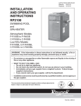
PRESSURE RELIEF VALVE
In some installations, a pressure relief valve (PRV) is required
on the MiniMax NT Series.
RELIEF
To install a PRV, carefully
VALVE
drill a 3/8 in. hole in center
of 3/4 in. NPT port (on
FOR PRV
INSTALLATION
main header) being careful
DRILL THRU
THE NPT PORT
to drill only through wall at
bottom of 3/4 in. NPT port
and no deeper—now thread
in the 3/4 NPT PRV.
REMOVE FLOW VALVE
NOTE: (A.S.M.E. version
varies slightly. It is of
bronze construction, and is
supplied with the A.S.M.E.
Section IV, pressure relief
valve pre-installed at factory.)
BEFORE DRILLING
THE NPT PORT
Figure 22.
RELIEF VALVE
Test the relief valve at least
once a year by lifting up
lever.
TO WINTERIZE,
OPEN DRAIN VALVE
STANDARD
LOW-NOx
Figure 21.
A.S.M.E. VERSION
SPRING AND FALL OPERATION
If the pool is being used occasionally, do not turn the heater completely off. Set the thermostat down to 68° F. This will keep the pool
and the surrounding ground warm enough to bring the pool up to a comfortable swimming temperature in a shorter period of time.
WINTER OPERATION
CAUTION
OPERATING THIS HEATER CONTINUOUSLY AT WATER TEMPERATURE BELOW 68° F. WILL CAUSE HARMFUL
CONDENSATION AND WILL DAMAGE THE HEATER AND WILL VOID THE WARRANTY.
If the pool won't be used for a month or more, turn the heater off at the main gas valve. For areas where there is no danger of water
freezing, water should circulate through the heater all year long, even though you are not heating your swimming pool. The MiniMax NT
Series should not be operated outdoors at temperatures below 0° F. for propane and -20° F. for natural gas. Where freezing is
possible, it is necessary to drain the water from the heater. This may be done by opening the drain valve, located at the inlet/outlet
header, (see Figure 22.), allowing all water to drain out of the heater. It would be a good practice to use compressed air to blow the
water out of the heat exchanger.
CAUTION
• If the heater has been drained for freezing condition, do NOT turn "ON" until the system is circulating water.
• Water trapped in the heat exchanger can result in freeze damage to the exchanger or headers. Freeze damage is
specifically not covered by the warranty.
Rev. B 2-11-04
P/N
NTSM03
26
Maintenance - Burner Tray Removal
At some time during the life of a heater, you may
need to inspect and repair the parts of the heater that
allows the gas to flow from the gas supply line into
the burners. If the heater won’t fire and you wish to
check these gas controls:
1. Turn off the gas supply.
2. Disconnect the gas union at the heater.
3. Remove the gas pipe installed into the gas
valve.
4. Remove the gas valve holding bracket.
5. Remove the gas valve wires.
6. Disconnect the ignition wire.
7. Slide the burner tray out.
8. You can remove the gas valve if you need to
check the inlet and outlet screens. (You will
have to remove the pilot tubing.)
9. Remove the bracket that holds the burners in
place.
10. Remove each burner and check for any
blockages.
MINIMAX NT (LOW NOx) VERSION
MINIMAX NT (STANDARD) VERSION
MINIMAX NT (STANDARD) VERSION
11. Remove the main burner orifices and check for
blockage.
NOTE
If the heater has been off for the winter or has been
installed, but not fired for an extended period of
time, insects will crawl into these orifices and the
pilot orifice and prevent the heater from firing.
NOTE
MINIMAX NT (LOW NOx) VERSION
P/N NTSM03
You can use this procedure if you have to change
fuel-type—natural to propane or vice versa. The
parts needed to convert the MiniMax NT Series
are: Gas valve, main burner orifices, pilot
orifice and module.
Rev. B 2-11-04
27
Maintenance - Desooting
COMMON CAUSES OF SOOTING
1. Low gas pressure.
2. Inadequate air supply or inadequate venting.
3. Foreign material in burners and orifices; dirt, spider
webs, etc.
4. Excessive water flow can cause condensation which will
contribute to sooting.
To remove a light soot formation without
removing the heater exchanger:
For heavy soot accumulation which cannot
be successfully removed by merely
brushing, the heat exchanger must be
removed from the heater.
1. Disconnect the plumbing at the unions. Remove the
thermistor, hi-limit wires from the inlet outlet heater.
1. Remove burner tray.
2. Remove top, inner lid, flue collector and baffles.
CAUTION
When lifting the heat exchanger out of the fire box,
use caution so as not to damage the fire wall.
WARNING
Soot is combustible — DO NOT USE WIRE BRUSH!
3. Using a brush with plastic or wood bristles, brush the
bottom of the tubes and then the top of the tubes.
4. Spray off residue with water. (Repeat steps 3-4 as needed).
5. Brush off burners.
6. Replace burner tray and baffles, then test fire.
7. If flames burn clean, replace baffles, flue collector, and top.
Rev. B 2-11-04
2. Remove the heat exchanger.
3. Place exchanger in an area that won’t be affected by
chemicals or strong detergents.
4. After spraying the exchanger with water, use a mixture
of detergent and water. Pour, spray or brush on.
5. Rinse the solution off of the tubes and inspect them,
repeat if necessary.
P/N
NTSM03
28
Maintenance - Reinstalling Heat Exchanger
1. Inspect fire box for damage or cracks that would allow
heat to leak out into the outer cabinet and controls.
5. Reconnect the inlet and outlet flange to the headers (use
new flange gaskets), be careful not to move the heat
exchanger and break the seal.
2. Remove any old sealant from fire box.
6. Reinstall baffles, flue collector, inner lid and top.
3. Apply new sealant to the fire box using a quality
industrial grade R.T.V. or equivalent. The sealant must
completely seal the space between the heat exchanger
and fire box, so that when the heater is firing, heat does
not escape to the outer cabinet.
CAUTION
Do not store combustible material, gasoline and
other flammable vapor and liquids in the vicinity
of this or any other appliance.
4. Place heat exchanger into the box and push down firmly,
until the heat exchanger sets solidly on the fire box.
P/N NTSM03
Rev. B 2-11-04
29
Troubleshooting
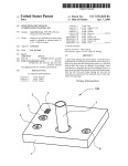
DIAGNOSTIC LIGHT OPERATION
The circuit board in the MiniMax NT Series heater uses lights that are wired in sequence with the
controls. The MiniMax NT Series heater still uses the same controls as the original MiniMax but this
method of wiring is more helpful while troubleshooting.
Sequence wiring means that each control is wired separately from the other controls and they are
independently attached to the circuit board. This is how the wiring method works to help diagnose a
problem.
Power is connected to the board directly from the Transformer. So, if the Transformer is wired
correctly and is being supplied with voltage, the Power light will be “ON”. This is not an indication that
proper voltage is being supplied by the Transformer.
When you push the “POOL/SPA” switch to either position and turn the thermostat knobs to “HOT”,
the voltage is transferred into the circuit board, through the Thermistor, Potentiometer and down to the
Remote Control terminals. If the Thermistor and Potentiometer are working the “TSTAT” light will
come “ON”.
If there is a Remote Control connected to these terminals, the voltage travels to the remote switch and
back to the circuit board and the “AUX” light comes “ON”. If there is no Remote, there will be a jumper
wire across the Remote terminals causing the “AUX” light to come “ON”.
If the voltage comes across the Remote Control terminals, it will go back into the circuit board and go
to the Pressure switch. If the Pump is “ON” and primed and there is enough water flow, the Pressure
switch will close and the “PRESS” light will come “ON”.
On the back of the circuit board, there are (3) more lights. “HIGH LIMIT”, “THERMAL CUT OFF”
and “PILOT VALVE”. Voltage must travel to and through the High Limits, Thermal Cut Off and finally
to the orange Pilot Valve wire before the Module will start to spark. And each time the voltage goes
through a control, indicating that the control is working, the voltage must go back to the circuit board,
where it lights the control indicator light.
24V
25D K .032 D.C TAB
J4
1
J3
J2
HLMT
JUMPER REQUIRED IF NO REMOTE SWITCH
TFUSE
PRESS
With this method of wiring we can easily see which control is not working by looking at the FIRST
LIGHT that is NOT LIT because we know that voltage has to pass through the control and back to the
board in order for the light to come “ON”. If the light is NOT “ON”, look at that control first.
1
IGN MODULE
VLV
J7
J11
JI0
1
1
AUX.
CONTACTS
TPROBE
THERMOSTAT
CONTROL RELAY
CLOSE ON CALL
FOR HEAT
J6
J8
J5
SPA
COM
POOL
P6
P8
P5
CIRCUIT BOARD
J9
P9
BLK
BLK
Figure 23.
TEMPERATURE
PROBE
POOL OFF SPA
THERMOSTAT SELECT SWITCH
Rev. B 2-11-04
P/N
NTSM03
30
Troubleshooting
1. The POWER Light indicates voltage to the
Control Board from the Transformer. The
POWER light will be ON without pushing the
Pool/Spa switch as long as there is power being
supplied to the transformer.
2. The TSTAT Light or Thermostat Light will
come ON if there is voltage to the
Potentiometers and they are turned to the Hot
Position and the water temperature is below
the hot set point.
3. The AUX Light or Remote Switch Light will
come ON if the Remote control is operating
properly and/or is attached to the back of the
Control Board correctly. If the heater is not
connected to a remote switch, there will be a
small jumper wire attached to the Control
Board to make the light come on.
4. The PRESS Light is attached to the Pressure
Switch and will come ON if the Pump is ON
and is pumping enough water to create
adequate water pressure to close the contacts
on the Pressure Switch.
DIAGNOSTIC LIGHTS
5. The HEAT Light is attached to the MV
(Main Valve) terminal on the Control Board.
This terminal does not receive voltage until
the Hot Surface Igniter (HSI) has been ON for
40 seconds. Once voltage is sent to the Gas
Valve, it should open to allow gas flow to the
burners that will be ignited by the HSI.
6. The SERVICE Light is a dual-purpose light.
When there is a call for heat the Service Light
will be ON during the 15-second pre-purge and
the 40 second Hot Surface Igniter (HSI)
heat-up period. The Service Light will be OFF
during the 7 second trial for Ignition when the
HEAT Light comes ON. If the burners fire
and the Flame Sensor sends a signal to the
Ignition Module that there is a successful
ignition, the Service Light will stay OFF and
the Heat light will stay ON. The Service light
will also be ON if there is a problem with one
or both of the High Limit Switches, the
Thermal Fuse or the Valve (VAL) output on
the Ignition Module.
Figure 24.
P/N NTSM03
Rev. B 2-11-04
31
Troubleshooting
MiniMax NT Series Heater Troubleshooting/Check List
1. Look at the lights, which ones are on? Review Diagnostic Lights section on previous page.
2. Check for correct voltage on Secondary side of Transformer. Should be greater than 24 VAC
at Orange Wire at 24 V position on Control Board.
3. Check all wire connections on Module, Control Board, HSI, Flame Sensor and Gas Valve.
4. Check position of HSI and Flame Sensor to Burners.
5. Check for true ground and good ground connections.
6. Push the Pool/Spa switch ON to the opposite side and then the thermostat from cold to hot.
7. Make sure that the pump is running with a full prime and that the filter pressure is not too
high or low.
8. Remove any Remote Control wires from the heater Control Board and replace with the jumper
wire while testing.
MiniMax NT (Standard) Wire Connection
ORANGE
ORANGE
WHITE
IG
NIT
CO
NN
EC
TO
R
GREEN
IO
OD
UL
IGN
/12
0
L1
IGN
FS
FLAME SENSOR
E
ORANGE
240 OR 120VAC
TH
VA
L
GN
D
AN
HIT
WH
ITE
WHITE
E
BL
UE
L2
GE
AN
OR
OR
W
W
HIT
IGN
/24
0
E
O
LL
YE
W
NM
ITE
GE
RED
BLAC
K
WH
BLAC
K/WHIT
E
RED/W
HITE
TO
FE
MA
LE
IGNITOR
TRANSFORMER
IND
24V
AC
F2
F1
W
HIT
E
GE
ORAN
WHITE
WHITE
120VAC
AIR PRESSURE SWITCH
BLACK
BLUE
GREEN
ORAN
GE
WHITE
RED
BLUE FEMALE
CONNECTOR
W
HIT
E
YE
L
BL L O
AC W
OR
K
AN
GE
PU
RP
LE
WHITE MALE
CONNECTOR
GREEN
WH
IT
RE E
D
BLU
240VAC
E
ND
OU
GR
WHITE
BLACK
ER
MP )
JU HT
(W
ITE
WH
HILIMITS
K
AC
BL
GAS VALVE
RE
WH D
T
RED/BROWN FEMALE
CONNECTOR
WHITE
FIELD
SUPPLIED
120 VAC
OR
240 VAC
60 Hz
POWER TERMINAL
BLOCK
WHI
WHITE
BLAC
RED
K
AC
BL
WHITE
BLAC
K
BLK
WHITE
WHITE
WHITE
TERMINAL BLOCK
THERMOSTAT SWITCH
POOL/OFF/SPA
THERMISTOR PROBE
ITE
WH
CK
BLA
POWER SWITCH
WHI
RED
TE
K
WHI
TE
L FUSE
THERMA
WHITE
TE
E
WHIT
WHI
(WHT)
HT)
(WHT)
SPA
L (W
MON
POO
COM
PENTAIR 6800
DUAL
ELECTRONIC
THERMOSTAT
TE
BLOWER
BLACK
BOND LUG
(ON THE SIDE OF JACKET)
WATER
PRESSURE
SWITCH
Figure 25.
Rev. B 2-11-04
P/N
NTSM03
32
Troubleshooting
DIAGNOSTIC LIGHTS SHOW
“POWER” ONLY!
1. Check water temperature, if water has reached the desired temperature, the thermostat will cut
off power to the module and the heater will stop firing. In this case the POWER Light would
remain ON.
2. Check the voltage on the Secondary side of the Transformer. It should be greater than 24 VAC.
If the voltage is less than required, the incoming voltage may be too low for the heater to operate
properly, there could be a wiring short or the wrong voltage connector may be connected to the
White Male Connector. Because the Power light is not a specific 24 VAC light, it will illuminate
with less than 24 VAC, so even if the Power Light is ON, the voltage may not be correct.
3. The Pool/Spa switch may have inadvertently been switched Off. Even though the Pool/Spa
switch does not have to be ON for the POWER Light to be ON, it does have to be pushed to
either the Pool or Spa position in order to transfer voltage to the rest of the controls.
4. Make sure that the Thermostat Knobs have been turned to Hot because the voltage must pass
through the thermostat (potentiometer) first before going to any other control. If the
potentiometer or thermistor is not working or is disconnected from the Control Board, only the
POWER Light will be ON. If you suspect that this may be the problem, first check the
thermistor connections on the back of the Control Board. If this does not light the T-STAT Light,
connect a known functional thermistor to the Control Board. If the light still does not come on,
the Control Board is bad.
Figure 26.
P/N NTSM03
Rev. B 2-11-04
33
Troubleshooting
POWER / T-STAT ONLY!
1. Check that jumper has not come off of EXT SWITCH terminals.
2. Remove Wires to External Switch or Remote Control System and replace with jumper.
If AUX Light comes ON, the problem is in External Switch or Remote Control System.
3. Check for 24 VAC at the OUT terminal of the EXT SWITCH connection.
If no voltage, Control Board is bad.
Figure 27.
2 Wire Remote
EXT SWITCH
24 VAC
OUT
PRESS HILMT
TFUSE
VALVE
IGNITION MOD
RETURN
POOL
SPA
MODEL 6800
ELECTRONIC THERMOSTAT
PVALV LED
TFUSE LED
HITEMP LED
POTENTIOMETER
TPROBE
SPA
COM
POTENTIOMETER
POOL
FRONT PANEL
POOL / OFF/SPA
THERMOSTAT SELECT SWITCH
Figure 28.
Rev. B 2-11-04
P/N
NTSM03
34
Troubleshooting
POWER / T-STAT / AUX ONLY!
1.
2.
3.
4.
Be sure that Pump is ON and running with a full prime.
Is Pump Impeller clogged.*
Is Filter Dirty.*
Is Pump too small or worn out.*
*30 GPM is required to close the Pressure Switch. Some 2 Speed pumps will not
produce 30 GPM on Low Speed.
5. Check for 24 VAC at outside White Wire on PRESS connector. If no voltage, Control Board is bad.
6. Check for 24 VAC at second White Wire on PRESS connector. If have voltage, Control Board is bad.
7. Check that wires are attached to Pressure Switch and check for 24 VAC at both terminals. If no
voltage at either terminal, wire is bad. If voltage at one terminal only, Pressure Switch is
clogged, out of adjustment or bad.
Figure 29.
MiniMax NT (Standard) Wire Connection
ORANGE
ORANGE
WHITE
HIT
E
IG
NIT
N
N
EC
TO
R
GREEN
IO
LE
C
O
IGNITOR
MA
ITE
NM
OD
WH
UL
E
/12
0
IGN
/24
IGN
L1
GE
L2
240 OR 120VAC
D
GN
VA
L
IGN
FS
TH
OR
AN
GE
OR
ORANGE
ORAN
UE
W
FLAME SENSOR
O
W
HIT
E
WH
ITE
WHITE
E
HIT
W
BL
LL
AN
HITE
RED
E
K/WHIT
RED/W
TRANSFORMER
YE
BLAC
BLAC
K
0
FE
TO
IND
24V
AC
F2
F1
W
GE
WHITE
WHITE
120VAC
BLACK
BLUE
GREEN
ORAN
GE
WHITE
RED
BLUE FEMALE
CONNECTOR
YE
L
BL LO
AC W
OR
K
AN
GE
PU
RP
LE
W
HIT
E
WHITE MALE
CONNECTOR
AIR PRESSURE SWITCH
GREEN
WH
IT
RE E
D
240VAC
BLU
E
GR
WHITE
BLACK
ER
MP )
JU HT
(W
GAS VALVE
BL
RE
WH D
T
RED/BROWN FEMALE
CONNECTOR
WHITE
OU
WH
HILIMITS
ND
ITE
AC
K
FIELD
SUPPLIED
120 VAC
OR
240 VAC
60 Hz
POWER TERMINAL
BLOCK
WHI
TE
WHITE
BLAC
K
WHI
TE
WHI
TE
L FUSE
WHITE
RED
WHITE
WHITE
POWER SWITCH
BL
TERMINAL BLOCK
THERMOSTAT SWITCH
POOL/OFF/SPA
THERMISTOR PROBE
ITE
WH
CK
BLA
A
CK
WHITE
BLAC
K
RED
BLK
THERMA
WHITE
TE
WHI
E
WHIT
SPA
(WHT)
POO
L (W
HT)
PENTAIR 6800
DUAL
ELECTRONIC
THERMOSTAT
COM
MON
(WHT)
BLOWER
BLACK
BOND LUG
(ON THE SIDE OF JACKET)
WATER
PRESSURE
SWITCH
Figure 30.
P/N NTSM03
Rev. B 2-11-04
35
Troubleshooting
POWER / T-STAT / AUX / PRESS / SERVICE
Fan Not Running
1. Check the 3 lights on the back of the Control Board. These 3 lights are
connected to 3 different controls in this order: #1 – High Limit,
#2 – Thermal Fuse, #3 – Gas Valve.
2. If all of the lights are out, the High Limit safety switches are keeping the
heater off. If the inlet water reaches 115 degrees or if the water from the heat
exchanger reaches 150 degrees the heater will not fire. Check for proper
water flow through heater. If water flow is correct, allow heater to cool and
check continuity of the High Limit Switches. If either switch shows an open
circuit when the heater is cool, replace the switch. See Figure 31.
3. If only the “High Limit” light is ‘ON’ (i.e. only one green light is on), the
Thermal Fuse circuit is keeping the heater off. If there is evidence of flame
roll-out at the Thermal Fuse location, it is probably burned out. Check
Thermal Fuse for continuity, if good, check wiring for continuity. If Thermal
Fuse is burned out, find reason for roll-out before putting heater back into
service. See Figure 32.
Figure 31.
4. If the “High Limit” and “Thermal Fuse” lights are ON (i.e. two green lights
ON), Check for 24 VAC at 24 VAC terminal on Ignition Module. If none,
check connections and wire back to Transformer. See Figure 33.
5. Check for 24 VAC at IND terminal on Ignition Module. If none, check
connections and wire back to Control Board and then for 24 VAC at orange
wire at connector at Control Board.
6. Check Fan connection on module (F1 & F2) for continuity if electric supply is
120VAC by removing plug and checking continuity across terminals. If no
continuity, module is bad. If the heater electric supply is 240 VAC, leave plug
in place and check for 120 volts from F1 to ground. If no voltage, module is
bad. See Figure 34.
Figure 32.
7. Check connections and wires from module and 120/240 plug connectors to fan
motor. Replace fan motor if necessary.
Figure 33.
Figure 34.
Figure 35.
Rev. B 2-11-04
P/N
NTSM03
36
Troubleshooting
POWER / T-STAT / AUX / PRESS / SERVICE
Fan Running / HSI not energized and
lock out occurs after 30 seconds
1. Check for 24VAC at TH terminal on Ignition Module.
If none, check connections and wire and check for
24VAC at white wire terminal on Fan Vacuum Switch.
If none, check Vacuum Switch operation, (see Vacuum
Switch Testing section later in this manual).
2. Check for 120VAC between IGN/120 & IGN terminal
on Ignition Module or 120VAC between IGN/240 &
IGN terminal on Ignition Module depending on electric
supply. If none, Ignition Module is bad.
White Wire
3. Check for 120VAC at HSI. If none, check connections
and wires. If you have 120 VAC at HSI and it’s not
functioning, the HSI is bad.
4. See HSI Testing section later in this manual for
additional testing information.
P/N NTSM03
Rev. B 2-11-04
37
Troubleshooting
POWER / T-STAT / AUX / PRESS / SERVICE
Fan Running / HSI Energized / No Gas to Burners
1. Check the green lights on back of
Control Board. If the “High Limit”
and “Thermal Fuse” are ON, (i.e.
only one light is OFF), there is no
voltage being supplied to the
Control Board from the Valve
(VAL) connection on the Ignition
Module. Check for 24 VAC at the
“VAL” connection on the Ignition
Module. If no voltage, Ignition
Module is bad.
2. Check for 24 VAC at the red wire
connected to the Ignition Module
terminals on the Control Board.
If none, check connections and red
wire for continuity.
Red Wires
Connect Here
Red Wire
3. Check for 24 VAC at the red wire
connected to the Valve connector on
the Control Board. If none, Control
Board is bad.
4. Check for 24 VAC at the red wire on
the Gas Valve. If no voltage, check
connections and red wire for continuity.
5. If there is voltage at the Gas Valve, be
sure that the gas valve and all shut off valves are turned ON, that the gas line has been bled and
that there is gas available.
6. If all valves are open and there is gas to the valve. Replace Gas Valve.
Rev. B 2-11-04
P/N
NTSM03
38
Troubleshooting
POWER / T-STAT / AUX / PRESS
HEAT (on then off) / SERVICE (off then on)
Fan Running / HSI Energized / Burners ignite and
the go off in 7 seconds or less
1. Check for 24 VAC at FS terminal on
Ignition Module If none, Ignition Module
is bad.
2. Check for 24 VAC at Connector on Flame
Sensor, if none, replace wire.
3. Check to make sure the Flame Sensor is
not shorted to Ground.
4. If Flame Sensor voltage and amperage are
OK, Ignition Module is bad.
P/N NTSM03
Rev. B 2-11-04
39
Troubleshooting
1. It is possible to bypass the 6800 Control
Board and, therefore, the thermostat and
safety circuits by installing a jumper from the
Orange Wire on the 24V connector to the
Orange Wire on the Ignition Module
connector. If the heater fires, the problem is
in the Control Board/Thermostat Circuit, the
Thermostat Temperature Sensor (Thermistor)
or the Control Circuit.
2. Each component in the Control Circuit can be
checked individually at the Control Board for
24 volts in and out, but the diagnostic lights
tell us if the circuit is good or bad (closed or
open); therefore, it is not necessary.
3. The Thermostat Thermistor can be checked
by removing the connector from the Control
Board and taking an Ohm reading at the end
of the connector. Compare this reading to
the following conversion table to see if it is
reading correctly. If it is not, replace the
thermistor.
Degrees
'F'
Resistance
(Ohms)
Degrees
'C'
59
15711
15
68
12492
20
77
10000
25
86
8057
30
95
6531
35
104
5326
40
TESTING THE
6800 CONTROL BOARD CIRCUITRY
Jumper
Orange Wires
Check resistance
across these two
White Wires
Table 13.
4. If 24 VAC is not present at the orange wire
on the Ignition Module connector, the
Control Board is bad.
Rev. B 2-11-04
P/N
NTSM03
40
Troubleshooting
THE SERVICE LIGHT
1. The primary responsibility for the SERVICE Light is to illuminate whenever there is a problem
that prevents the heater from firing (please see Diagnostic Lights explanation at the beginning of
this section). However, it will also be ON during the Fan 15-second pre-purge and the 40-second
Hot Surface Igniter heat up.
2. The SERVICE Light also comes ON if the burners do not continue to burn properly or if the
flame goes out, if there is a bad Flame Sensor or Flame Sensor wire or if anything else causes the
Ignition Module to restart the ignition sequence. So, if the SERVICE Light comes ON and heater
stops firing and then the heater fires and the SERVICE Light goes out, simulating a Rapid Cycle,
it can be caused by a loss of or weak signal to the Ignition Module by the Flame Sensor.
3. The SERVICE Light will come ON if the water temperature in the Inlet side of the Header
reaches 115 degrees or if the water temperature at the outlet of the heat exchanger reaches 150
degrees. If the heater is cycling in this mode, the three green lights on the back of the Control
Board will flash OFF and ON as the heater shuts down and refires.
NOTE
If a weak Flame Sensor signal causes the cycling, the SERVICE Light will go ON and OFF, but
the High Limit Light will remain ON. If water temperature causes the cycling, the SERVICE Light
will go ON and OFF AND the High Limit will go ON and OFF as well.
EXT SWITCH
24 VAC
OUT
PRESS HILMT
TFUSE
VALVE
IGNITION MOD
RETURN
POOL
SPA
MODEL 6800
ELECTRONIC THERMOSTAT
PVALV LED
TFUSE LED
HITEMP LED
POTENTIOMETER
TPROBE
SPA
COM
POTENTIOMETER
POOL
FRONT PANEL
POOL / OFF/SPA
Figure 36.
P/N NTSM03
THERMOSTAT SELECT SWITCH
Rev. B 2-11-04
41
Troubleshooting
TESTING THE FAN VACUUM SWITCH
1. The Fan Vacuum Switch is a normally open switch
that closes on a decrease of pressure in the fan exhaust
housing. It then sends 24 VAC through the white wire
to the Ignition Module at the TH terminal to start the
ignition sequence. Applying a vacuum to the barbed
fitting where the orange tube is attached can test the
switch and its circuit. To perform this test, SHUT
OFF POWER, connect the leads of a multimeter set
to Ohms to each terminal on the switch, remove orange
tube from switch and, using a short piece of ¼ in. ID
tube attached to the barbed fitting, draw air from the
switch to see if it closes.
Attach ¼” ID
Test Tube here
Check Continuity
from White to
Orange Wire with
Power turned OFF
2. Checking to see if there is 24 VAC on the white wire
terminal can also check the Fan Vacuum Switch during
operation.
3. If the Fan Vacuum Switch is good but it does not close
when the fan is operating and, therefore, power is not
sent to the Ignition Module, the problem is in the orange
tube or the connector in the Fan Housing is clogged.
4. If the Fan Vacuum Switch closes but 24 VAC is not sent
to the Ignition Module, the problem is in the white wire.
Troubleshooting
Orange Vacuum Tube
connector in Fan Housing
TESTING THE
HOT SURFACE IGNITOR (HSI)
1. The Hot Surface Igniter can be checked four different ways:
a. Voltage Check: Check for 120 VAC across two wires
after 15 second pre purge time has expired.
b. Amp Draw: Check the HSI circuit for 0.5 +/- .05 amps
after 15 second pre purge time has expired, (see picture).
c. Continuity: Turn OFF electric supply to heater,
disconnect HSI leads and, using an Ohm setting, look
for any reading greater than zero or OL.
d. Visual: Remove burner Flash Back Shield to allow
visual inspection. The HSI should glow for about 47
seconds after the 15-second pre-purge cycle. It also
should be located above and parallel to the burner.
2. Before replacing the HSI, be sure that the heater frame and electric circuit are properly grounded,
as this will affect the performance of both the HSI and the Flame Sensor.
Rev. B 2-11-04
P/N
NTSM03
42
Troubleshooting
RAPID CYCLING
If the heater fires, shuts down and refires every 30-45 seconds and the Service Light comes ON and
goes OFF alternately with the Heat Light, this indicates that the Inlet or Outlet High Limit Switch is
sensing a temperature greater than 115° of 150° F., respectively. This is generally caused by a lack of
water inside the heat exchanger, while the heater is firing.
Things To Look For:
1.
2.
3.
4.
5.
6.
The pump is worn out.
The pump isn’t pumping enough water.
The pump impeller is plugged.
A valve on the outlet side of the heater has been closed.
The pump is a 2 speed that is operating on low speed.
Something is blocking the water flow through the heat
exchanger.
7. The flow valve is defective or damaged.
Troubleshooting
Outlet High Limit
Inlet High Limit
ADJUSTING FLOW VALVE
The flow valve is installed in the inlet/outlet header and allows
a small portion of the water to pass through the heat exchanger
when the heater is not firing. When the heater fires, as the water
leaving the exchanger warms, the flow valve forces more water
into the exchanger by partially closing the by-pass opening.
You can test the flow valve by removing it from the heater and
placing the power element in hot water. If the power element
rod extends and forces the by-pass disc to move toward the
mounting plate and retracts when placed in cold water, the flow
valve is OK, but if it does not move, replace the power element. The power element is copper, so water
with a low pH (7.4 or lower) and or water velocity (too much flow) will cause the element to fail and the
heater will cycle rapidly.
If there is not enough water in the heat exchanger to prevent the heater from cycling, the inlet/
outlet header will be too hot to touch.
If you check all the water related causes of rapid cycling and do not find the problem, an electrical
nuisance shut down may be causing the cycling. (wiring connections, inadequate grounding, defective
or not properly aligned Flame Sensor). However, if you have followed the directions in the “BEFORE”
troubleshooting section, the wiring problems should be minimal.
•
•
•
4¼”
P/N NTSM03
Diverter.
Power element.
When replacing or adjusting the power
element, use a measurement of 4¼”
between the diverter and retention cap face.
Rev. B 2-11-04
43
Troubleshooting
PROPER COMPONENT VOLTAGES
Pressure switch (water) .................................................................................................. 24 volts
High limit switch (outlet) .............................................................................................. 24 volts
High limit switch (inlet) ................................................................................................ 24 volts
Thermal fuse (fusible link) ............................................................................................ 24 volts
Gas valve ....................................................................................................................... 24 volts
Thermostat board ........................................................................................................... 24 volts
Transformer (secondary) ................................................................................................ 24 volts
Flame rectifier (signal sent back to module) ........................................ (7 micro amps) 24 volts
Hot surface igniter (only when heater firing) .............................................................. 120 volts
Reset switch .......................................................... (depends on input voltage) 120 or 240 volts
Fan motor .............................................................. (depends on input voltage) 120 or 240 volts
Troubleshooting
FENWAL IGNITION
SEQUENCING MODULE
F1 – (Power output for fan circuit)
F2 – (white wire) 120 volts input – Fan circuit- when wired for 240vac
F2 – (white wire) Neutral when wired 120vac
24VAC – (orange wire marked 24 volts) – 24 volt supply to ignition module (this wire is hot
whenever the transformer is energized) - this is a direct lead
IND – (orange wire marked IND) – 24 volts from T-stat board when heater switch ON triggered
by the completion of the safety circuit.
Rev. B 2-11-04
P/N
NTSM03
44
CONTROL WIRE
TERMINAL DESIGNATION
Troubleshooting
IGN/120 – 120 volt supply for Hot Surface Igniter (only when supply is 120 volts)
IGN/240 – 120 volt supply for Hot Surface Igniter (only when supply is 240 volts)
L1 – (black wire) Line supply voltage to module (120 volts)
L2 – (white wire) Line supply voltage to module (neutral only if heater supplied by 120 volts)
IGN – (white wire) 120 volt output to Hot Surface Igniter (only when heater firing)
FS – (white wire) 24 volts to flame rectifier (constant). This is a communication wire there will
be signals sent in both directions on this wire (24vac to the sensor 7 Micro amps returning).
TH – (white wire) 24 volts from Low Pressure Switch (fan)
VAL – (red and blue wires) 24 volts to open gas valve
Only the blue wire is used by the gas valve even though both have been energized.
GND – (white wire) 24 volt ground
BL
Y
BK
W
W
W
W
R
BL
W
F1
IGN/120
F2
IGN/240
24 VAC
L1
IND
L2
O
IGN
FS
TH
VAL
GND
IGN MODULE
P/N NTSM03
O
Figure 37.
Rev. B 2-11-04
45
STEP-BY-STEP ELECTRICAL TROUBLESHOOTING
OF THE
MINIMAX NT SERIES HEATER w/6800 BOARD
•
Power to the heater should be configured properly at the terminal block, (for 120v the neutral lead
always goes to the center lug of terminal block).
•
From the terminal block the power flows through the internal shut off switch at the bottom of the
J-Box. (This voltage will be the same as the supply voltage for the heater.)
•
The power now is divided between the 120v and 240v female connectors; (from the factory the
heater is configured for 240v to avoid damage to the transformer).
•
The male connector should be plugged into the proper 120v or 240v female connector before turning
on the heater. This provides the proper voltage to the transformer, fan and ignition module.
•
High voltage supplied to the transformer is changed to 24vac to control the ignition process, (output
voltage is relative to the input voltage and it should range from 24-29vac). Voltage readings below
24vac indicate a problem. (NOTE: The heater is also certified at 85% of 120v/240v too, therefore,
the voltage could be as low as 22.5. However, we do NOT recommend operating the heater at that
condition for a long period at all.)
•
The 24vac from the transformer is supplied to the 24vac terminal on the circuit board as well as the
24vac lead on the module. This is the main power supply for the circuit board as well as the module.
•
To start the ignition process, there must be a call for heat. This is provided by the thermostat circuit
on the circuit board. If the thermostats are turned up and the pool/spa switch is in either the Pool or
Spa position, if there is no call for heat, then check the temperature probe connection on the back of
the circuit board. If the connection is good, test with a known good sensor.
•
Once the thermostat circuit is completed, power is supplied to the safety circuit. The power flows as
follows:
1. From the circuit board to the pressure switch and back to the board (this will illuminate the
pressure light (PRESS) on the front of the board).
2. From the circuit board to the high limits and back to the board, (this will illuminate the high
limit light (HTEMP) on the back of the board).
3. From the circuit board to the thermal fuse and back to the board, (this will illuminate the T-fuse
light (TFUSE) on the back of the board).
•
When the thermostat circuit and safety circuits have been completed, 24vac is supplied to the
fan-proving switch, (where it will wait for the fan to come on), and to the IND terminal on the top
left of the ignition module.
•
When the IND terminal is energized, the contactor between F1 and F2, (inside the Fenwal Module),
closes sending power to the fan. If the fan does not come on, disconnect the wires between F1 and
F2 and check for continuity through F1 and F2 with the IND terminal energized.
(continued on next page)
Rev. B 2-11-04
P/N
NTSM03
46
STEP-BY-STEP ELECTRICAL TROUBLESHOOTING
OF THE
MINIMAX NT SERIES HEATER w/6800 BOARD
•
When the fan comes on, it transfers a low pressure (vacuum) to the fan-proving switch. This low
pressure closes the fan-proving switch, which then allows 24vac to be supplied to the TH terminal
on the ignition module. This starts the Ignition phase of the heater.
1.
2.
3.
4.
15 seconds of pre purge.
40 seconds of HSI heat up time.
7 seconds of flame rectification, (heater runs until no longer calling for heat).
45 seconds of post purge.
•
After the 15 seconds of pre-purge, the IGN terminal on the module will be energized for 40 seconds
to supply 120vac to the HSI prior to the opening of the gas valve.
•
After the 40 second heat up of the HSI, 24vac is supplied from the VAL terminal on the module to
the circuit board at the connection labeled “Module”. This is done to activate the heat light (HEAT)
on the front of the board as well as the PV light on the back of the board. The service light will go
out when the heat light comes on.
•
24vac is then supplied from the VLV terminal on the circuit board to energize the gas valve using
the blue wire.
•
Once the gas valve is open, the gas is exposed to the heat generated by the HSI and ignites.
•
From the time the ignition module is energized, (at the 24vac terminal), the flame sensor,
(NOT available for LN heater), is supplied with 24vac as well. Now that there is a flame between
the burner tray and the flame sensor, that same 24vac signal has a path to ground. This completes
the flame rectification circuit and discontinues the power supply to the hot surface igniter.
(NOTE: If the flame rectification circuit is compromised, the heater will shut down and attempt the
ignition process again.)
NOTE: The heater will shut down under the following conditions:
1.
2.
3.
4.
Outlet high limit opens up due to pool or spa water flow temperature.
Inlet high limit opens up due to pool or spa water temperatures in excess of 115° F.
Thermal fuse opens up due to roll out condition.
Fan proving switch does not close or open up during operation due to an obstruction of venting
or use of excessive vent piping.
5. Flame rectification is lost due to insufficient gas supply, improperly positioned or defective
flame sensor.
P/N NTSM03
Rev. B 2-11-04
47
Glossary
1. BURNER: A device for the final conveyance of gas,
or a mixture of gas and air, to the combustion zone.
2. BUTANE: A hydrocarbon fuel gas heavier than
methane and propane and a major constituent of
liquefied petroleum gases.
3. CIRCUIT BOARD: Interprets signals from
potentiometers and thermistor.
4. COMBUSTION: The rapid oxidation of fuel gases
accompanied by the production of heat or heat and
light.
5. COMBUSTION AIR: Air supplied in an appliance
specifically for the combustion of a fuel gas.
6. CUBIC FOOT OF GAS: (Standard Conditions).
The amount of gas which will occupy 1 cubic foot
when at a temperature of 60° F. and under a pressure
equivalent to that of 30 inches of mercury.
7. DRAFT HOOD: (Draft Diverter). A device built
into an appliance, or made part of a vent connector
from an appliance, which is designed to: (1) assure
the ready escape of the products of combustion in
the event of no draft, backdraft, or stoppage beyond
the draft hood; (2) prevent backdraft from entering
the appliance; and (3) neutralize the effect of stack
action of a chimney or gas vent upon the operation
of the appliance.
8. DOWNDRAFT: Excessive high air pressure
existing at the outlet of chimney or stack which
tends to make gases flow downward in the stack.
9. FLASHBACK: An undesirable flame characteristic
in which burner flames strike back into a burner to
burn there or to create a pop after the gas supply has
been turned off.
10. FLUE GASES, FLUE PRODUCTS: Products of
combustion and excess air in appliance flues or heat
exchangers before the draft hood.
11. GAS VALVE: A device that allows gas to flow
from the gas supply line into the pilot assembly and
into the main burners after receiving voltage from
the module.
12. HEAT EXCHANGER: Any device for transferring
heat from one fluid to another.
13. HIGH LIMITS: Devices installed into the outlet
side of the inlet/outlet header, designed to shut
heater off when water temperature reaches 150° F.
14. LIQUEFIED PETROLEUM GASES: The terms
“Liquefied Petroleum Gases” “LPG” and “LP Gas”
mean and include any fuel gas which is composed
Rev. B 2-11-04
predominantly of any of the following hydrocarbons,
or mixtures of them: propane, propylene, normal
butane or isobutane and butylenes.
15. MANIFOLD: The conduit of an appliance which
supplies gas to the individual burners.
16. MODULE: Device that sends signals to the pilot
ignitor and gas valve. The module starts the pilot
spark and main burner sequence.
17. NATURAL GAS: Any gas found in the earth, as
opposed to gases which are manufactured.
18. ORIFICE: An opening in an orifice cap (hood),
orifice spud or other device through which gas is
discharged, and whereby the flow of gas is limited
and/or controlled.
19. POTENTIOMETER: Registers desired
temperature setting on circuit board.
20. PRESSURE SWITCH: A normally open switch
that closes with adequate water pressure.
21. PRIMARY AIR: The combustion air introduced
into a burner which mixes with the gas before it
reaches the port. Usually expressed as a percentage
of air required for complete combustion of the gas.
22. PROPANE: A hydrocarbon gas heavier than
methane but lighter than butane. It is used as a fuel
gas alone, mixed with air or as a major constituent
of liquefied petroleum gases.
23. SOOT: A black substance, mostly consisting of
small particles of carbon, which can result from
incomplete combustion and appear as smoke.
24. TRANSFORMER: A coil device that changes high
voltage to low voltage.
25. THERM: A unit of heat energy equal to 100,000 Btu.
26. THERMAL CUT OFF: A one shot soldered pill
type fuse that melts and interrupts power to the
controls if the temperature becomes to high in the
gas valve area.
27. THERMISTOR: Installed in the inlet/outlet header,
senses water temperature and tells circuit board
when to shut heater off.
28. VENT: A device, such as a pipe, to transmit flue
products from an appliance to the outdoors. This
term also is used to designate a small hole or
opening for the escape of a fluid (such as in a gas
control).
29. WATER COLUMN: Abbreviated as W.C. A unit
used for expressing pressure.
P/N
NTSM03
48
MINIMAX NT SERIES HEATER (Non-ASME Shown)
(Dual Voltage w/6800 Controller)
1
2
3
4
5
6
7
8
13
9
14
10
15
11
16
12
18
17
29
19
20
30
36
31
24
32
25
22 27 26 28 21 23
33
34
35
37
38
39
45
P/N NTSM03
44
43 42
41
40
Rev. B 2-11-04
49
+
J
*
Z[[\]^_=
!" #
$ $ % '
;< < => = ?@ ! K < => !" #
$ = '<Q
U = '<Q
% $ !" #
= '<Q => = '<Q => $XX = '<Q
+
J
*
+
J
! "
= ?@ ! ! ? \ %]
= ?@ ! ! ? *\ %]
U ^ '
;<_ ^"?=> !" #
;<_ ` < => !" #
;<_ $! ^"?=>
;<_ $! ^"?=>
_?K <Q >
> $ > K <Q
> $ > {
% < " ^
% | !" #
!< % | ^"? `< X > Q
| ? } | ? <
$ < # !" # } $ < # !" # <
;Q< % ! ^<
`< X > _ X ' } *?***~
`< X > _ X ' < *?***~
_ X ' } *?***~
_ X ' < *?***~
*
+
J
*
}
}
}
}
}
$ <
$ < $ '
' < @X
' < K Q
' ^"? <' < $ !" #
^ ' *?***~
`> ;Q< < < ! < !" #
K Q !" # < K Q !" # U_ < @X !" #
! ?XX Z} ^<[
<X ! * | Z} ^<[
U = < !" # Z} ^<[
;<> |< > Z} ^<[
}<?!" " $ Z} ^<[
" #"$ + $>
Rev. B 2-11-04
$$` $ + Z*******[
+
**+
*
J*
*
*
+
Z*******[
Z*******[
J*
J*
J
*
*
**
**
**
*
JJ
*+
+
J
+
J+
++
J
J
J
+J
+
J
JJ
*
J
*
**J
*
*
*
*
*
J
J
*
*
*
*
*
*
*
*+
*
*+
J
**
*
***
J**
J*
$ % +< $
J*
*
*+*
*+
*+
+
J+
*
**Z{[ **Z{[
J
J
J
= P/N
NTSM03
50
MINIMAX NT LOW NOx HEATER (Non-ASME Shown)
(Dual Voltage w/6800 Controller)
1
2
3
4
5
6
7
8
13
9
14
10
15
11
30
16
12
18
29
17
31
19
32
20
24
33
36
34
35
37
22 27 26 28 21 23
25
38
39
45
P/N NTSM03
44
43
42 41
40
Rev. B 2-11-04
51
+
J
*
Z[j\]^_=
!" #
$ $ % '
;< < => = ?@ ! K < => !" #
$ = '<Q
U = '<Q
% $ !" #
= '<Q => = '<Q => $XX = '<Q
+
J
*
+
J
*
! "
= ?@ ! ! ? \ %]
= ?@ ! ! ? *\ %]
U ^ '
;<_ ^"?=> !" #
;<_ ` < => !" #
;<_ $! ^"?=>
;<_ $! ^"?=>
_?K <Q >
> $ > K <Q
> $ > {
% < " ^
% | !" #
!< % | ^"? `< X >
^ '
| ? } $ < # !" #
;Q< `< X > _ X ' *?***~
_ X ' *?***~
$ <
+
J
*
' < @X
' < K Q
' ^"? <' < $ !" #
^ ' *?***~
`> ;Q< < < ! < !" #
K Q !" # < K Q !" # U_ < @X !" #
! ?XX Z} ^<[
<X ! * | Z} ^<[
U = < !" # Z} ^<[
;<> |< > Z} ^<[
}<?!" " $ Z} ^<[
}
}
}
}
}
$$` $ + Z*******[
+
+
Z*******[
+
Z*******[
" #"$ q% +z{
= + $>
Rev. B 2-11-04
J*
J*
J
*
J
*
**
**
*
JJ
*+
+
J
+
J+
J
J
**+
J*
**
**
++
J
+J
*
+
J
JJ
*
J
*
**J
*
*
J
*+
*
*
J
J
**
**
J+
**
J+
+
J**
J*
*
*+*
*+
*+
+
J+
*
**Z{[ **Z{[
J
J
$ % +< $
+J
J
P/N
NTSM03
52
40
SAVE THESE INSTRUCTIONS.
Pentair Pool Products, Inc.
1620 Hawkins Ave., Sanford, NC 27330 • (919) 774-4151
10951 W. Los Angeles Ave., Moorpark, CA 93021 • (805) 523-2400
P/N NTSM03
Rev. B 2-11-04