1
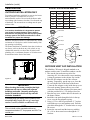
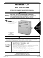
1 1
MiniMax CH
®
POOL & SPA HEATERS
OPERATION & INSTALLATION MANUAL
WARNING
FOR YOUR SAFETY - READ BEFORE OPERATING
Warning: If you do not follow these instructions exactly, a fire or explosion may
result, causing property damage, personal injury or loss of life.
For additional free copies of this manual; call (800) 831-7133.
To
Consumer
Retain For
Future
Reference
U.S. Patent Numbers
6,295,980
5,318,007 - 5,228,618
5,201,307 - 4,595,825
WARNING
Warning: Improper installation, adjustment, alteration, service or maintenance can
cause property damage, personal injury or death. Installation and service must be
performed by a qualified installer, service agency or the gas supplier.
WHAT TO DO IF YOU SMELL GAS
For Your
Safety
•
•
•
•
Do not try to light any appliance.
Do not touch any electrical switch; do not use any phone in your building.
Immediately call your gas supplier from a neighbor's phone.
Follow the gas supplier's instructions.
If you cannot reach your gas supplier, call the fire department.
Do not store or use gasoline or other flammable vapors and
liquids in the vicinity of this or other appliances.
Pentair Pool Products, Inc.
1620 Hawkins Ave., Sanford, NC 27330 • (919) 774-4151
10951 W. Los Angeles Ave., Moorpark, CA 93021 • (805) 523-2400
Rev. B 1-17-03
P/N 472128
2
Table of Contents
Introduction ...............................................................................................................
3
Important Notices ......................................................................................................................................................................
3
Warranty Information .................................................................................................................................................................
4
Operation ....................................................................................................................
4
Safety Rules ..............................................................................................................................................................................
4
Millivolt Lighting/Operation - Natural & Propane ........................................................................................................................
5
Operating (Controls) ..................................................................................................................................................................
6
Maintenance ...............................................................................................................
7
Maintenance Instructions ...........................................................................................................................................................
7
Relief Valve ................................................................................................................................................................................
7
Energy Saving Tips ....................................................................................................................................................................
7
Spring and Fall Operation ..........................................................................................................................................................
7
Winter Operation .......................................................................................................................................................................
7
Chemical Balance ......................................................................................................................................................................
8
Installation Instructions ............................................................................................
9
Specifications ..........................................................................................................................
9
Plumbing Connections ........................................................................................................... 10
Plumbing/Valves ........................................................................................................................................................................ 10
Manual Bypass ..........................................................................................................................................................................
10
Below Pool Installation ..............................................................................................................................................................
10
Water Connections.................................................................................................................. 11
Reverse Water Connections ......................................................................................................................................................
11
Insulating High Limits when Reversing Heads ...........................................................................................................................
11
Gas Connections ..................................................................................................................... 12
Gas Line Installation .................................................................................................................................................................. 12
Pipe Sizing Chart/Gas Pressure Requirements ......................................................................................................................... 12
Pipe Sizing Chart/Propane 2 Stage Regulation ......................................................................................................................... 13
Regulated Manifold Pressure Test .............................................................................................................................................
13
Ventilation ................................................................................................................................ 14
Outdoor Installation Requirements ............................................................................................................................................
14
Outdoor Cap Installation ............................................................................................................................................................ 14
Indoor Installation Requirements ............................................................................................................................................... 15
Installation on Floors Constructed of Combustible Materials ..................................................................................................... 16
Indoor Draft Hood Installation .................................................................................................................................................... 16
Electrical .................................................................................................................................. 17
Millivolt Wiring Diagram ............................................................................................................................................................. 17
Trouble Shooting (General) ....................................................................................... 18
MiniMax CH Parts List & Exploded View ................................................................. 19-21
MiniMax CH (150 IID Model) Appendix ..................................................................... A1-A9
MiniMax CH (150 IID Model) Parts List & Exploded View ....................................... A10-A12
Warranty Information .................................................................................................
P/N 472128
Back Cover
Rev. B 1-17-03
3
Introduction
MiniMax CH
Pool and Spa Heaters
Congratulations on your purchase of a MiniMax CH high performance heating system. Proper installation
and service of your new heating system and correct chemical maintenance of the water will ensure years of
enjoyment. The MiniMax CH is a compact, lightweight and efficient gas fired high performance pool and
spa heater that can be directly connected to schedule 40 PVC pipe and has a built-in top. The MiniMax CH
is a millivolt heater and has a self sustaining pilot and requires NO external power source.
IMPORTANT NOTICES
...For the installer and operator of the MiniMax CH pool and spa heater. The manufacturer’s warranty may
be void if, for any reason, the heater is improperly installed and/or operated. Be sure to follow the
instructions set forth in this manual. If you need any more information, or if you have any questions
regarding to this pool heater, please contact Pentair Pool Products, Inc. at (800) 831-7133.
These heaters are designed for the heating of swimming pools and spas, and should never be employed for
use as space heating boilers, general purpose water heaters, in non-stationary installations, or for the heating
of salt water.
CAUTION
OPERATING THIS HEATER CONTINUOUSLY AT WATER TEMPERATURE BELOW 68° F. WILL CAUSE
HARMFUL CONDENSATION AND WILL DAMAGE THE HEATER AND WILL VOID THE WARRANTY.
Do not use the heater to protect pools or spas from freezing if the final maintenance temperature desired is
below 68° F. as this will cause condensation related problems.
CODE REQUIREMENTS
The installation must conform with local codes or in the absence of local codes with the latest
National Fuel Gas Code, ANSI Z223.1, and the latest edition of the National Electrical Code, NFPA 70.
Installation in Canada to be made in accordance with the latest CAN/CGA-B149.1 or .2 and
CSA C22.1 Canadian Electric Code, part 1.
Rev. B 1-17-03
P/N 472128
Operation (contd.)
4
This instruction manual provides operating
instructions, installation and service information for
the MiniMax CH high performance heater. The
information in this manual applies to the MiniMax
CH 150, 200, 250, 300, 350, and 400 natural gas
and propane (LP) models.
It is very important that the owner/installer read and
understand the section covering installation
instructions, and recognize the local and state codes
before installing the MiniMax CH. History and
experience has shown that most heater damage is
caused by improper installation practices.
WARRANTY INFORMATION
The MiniMax CH pool heater is sold with a limited
factory warranty. Specific details are described on
the back cover of this manual and a copy of the
warranty and warranty registration card are
included with the product. Return the warranty
registration card after filling in the serial number
from the rating plate inside the heater.
Pentair Pool Products’ high standards of excellence
include a policy of continuous product improvement
resulting in your state-of-the-art heater. We reserve
the right to make improvements which change the
specifications of the heater without incurring an
obligation to update the current heater equipment.
Operation
SAFETY RULES
1. Spa or hot tub water temperatures should never
exceed 104° F (40° C). A temperature of 100° F
(38° C) is considered safe for a healthy adult.
Special caution is suggested for young children.
2. Drinking of alcoholic beverages before or during
spa or hot tub use can cause drowsiness which
could lead to unconsciousness and subsequently
result in drowning.
3. Pregnant women beware! Soaking in water
above 102° F (39° C) can cause fetal damage
during the first three months of pregnancy
(resulting in the birth of a brain-damaged or
deformed child). Pregnant women should stick
to the 100° F (38° C) maximum rule.
4. Before entering the spa or hot tub, the user
should check the water temperature with an
accurate thermometer. Spa or hot tub
thermostats may err in regulating water
temperatures by as much as 4° F (2.2° C).
5. Persons with a medical history of heart disease,
circulatory problems, diabetes or blood pressure
problems should obtain their physician's advice
before using spas or hot tubs.
6. Persons taking medication which induce
drowsiness, such as tranquilizers, antihistamines
or anticoagulants should not use spas or hot
tubs.
WARNING
Should overheating occur or the gas supply fail to shut off, turn off the manual gas control valve to the
appliance. Do not use this heater if any part has been under water. Immediately call a qualified service
technician to inspect the heater and to replace any part of control system and gas control which has been
under water.
P/N 472128
Rev. B 1-17-03
Operation (contd.)
5
MINIMAX CH MILLIVOLT LIGHTING/OPERATION-NATURAL GAS & PROPANE
FOR YOUR SAFETY: READ BEFORE LIGHTING
WARNING
If you do not follow these instructions exactly, a fire or explosion may result causing personal injury, loss of life
and property damage.
Since propane gas is heavier than air, escaping propane will accumulate and remain at ground level. Do not
attempt to light the heater. If you suspect a propane leak, lighting the heater can result in a fire or explosion
which can cause personal injury, death, and property damage.
A. This heater is equipped with a pilot which must be
lighted manually. When lighting the pilot, follow
these instructions exactly.
B. BEFORE LIGHTING smell all around the heater
area for gas. Be sure to smell next to the floor
because some gas is heavier than air and will settle
on the floor.
WHAT TO DO IF YOU SMELL GAS
- Do not try to light any heater.
- Do not touch any electrical switch; do not use any
phone in your building.
- Immediately call your gas supplier from a neighbor's
phone. Follow the gas supplier's instructions.
-
If you cannot reach your gas supplier, call the Fire
Department.
C. Use only your hand to push in or turn the gas control
knob. Never use tools. If the knob will not push in or
turn by hand, don't try to repair it. Call a qualified
service technician. Forced or attempted repair may
result in a fire or explosion.
D. Do not use this heater if any part has been under
water. Immediately call a qualified service
technician to inspect the heater and to replace any
part of the control system and any gas control which
has been under water.
LIGHTING INSTRUCTIONS
1.
2.
3.
4.
STOP! Read the safety information above.
Set the thermostat to the lowest setting.
Turn off electric power to the heater.
Push in gas control knob slightly and turn clockwise
to “OFF”.
7.
•
•
Robertshaw Millivolt Gas Valve
Figure 1.
Honeywell Millivolt Gas Valve
Figure 2.
Gas control knobs shown in “OFF” position.
NOTE
Knob cannot be turned from “Pilot to “OFF”” unless
knob is pushed in slightly. DO NOT FORCE.
5.
6.
Wait five (5) minutes to clear out any gas. If you then
smell gas, STOP! Follow "B" in the safety information above. If you don't smell gas, go to the next step.
Push in gas control knob slightly and turn counterclockwise
to “Pilot”.
8.
9.
10.
Push the control knob all the way and hold in.
Immediately light the pilot with Presslite matchless
ignition system by pressing the red igniter button
(located at the panel next to the gas valve). Continue
to hold the control knob in for about one (1) minute
after the pilot is lit. Release knob and it will pop
back up. Pilot should remain lit. If it goes out, repeat
steps 4 through 7.
If knob does not pop up when released, stop and
immediately call your service technician or gas
supplier.
Figure 3.
If the pilot will not stay lit
after several tries, turn the
gas control knob to “OFF”
and call your service
technician or gas supplier.
Turn knob on gas control
counterclockwise
to
“ON”.
Replace the control access
door.
Set the thermostat to the
Figure 4. Pilot
desired setting.
TO TURN OFF GAS TO HEATER
1. Set the thermostat to lowest setting.
2. Turn off all electric power to the heater if service is
to be performed.
3. Remove control access door.
Rev. B 1-17-03
4. Push in gas control knob slightly and turn clockwise
to "OFF". Do not force.
5. Replace control access door.
P/N 472128
Operation (contd.)
6
OPERATING (CONTROLS)
Dual Temperature Control System
For convenience and economy all MiniMax CH
heaters are equipped with two thermostats on the
front of the heater control panel; see Figure 5.
POOL
THERMOSTAT KNOB STOPPER
SPA
OFF
Each thermostat is equipped with a mechanical
stop that can be locked or unlocked with use of a
screwdriver to prevent temperatures in excess of
that desired by the user; see Figure 6.
The maximum setting can be adjusted by
COLD POOL TEMP HOT COLD SPA TEMP
HOT
loosening the screw "A" and turning the stopper
dial to desired maximum setting. Lock the setting
Figure 5.
by tightening the screw. The Mechanical stop is
under the knob. Ensure that the knob is stopping at the correct position when the knob is rotated clockwise
from a lower temperature position. (See Thermostat Adjustment.)
NOTE
To eliminate error due to piping heat losses, measure pool temperature with an accurate
thermometer directly at the pool or spa.
THERMOSTAT ADJUSTMENT
The knob with locking feature eliminates the need for
constant thermostat adjustments. Set the knob pointer to
the desired pool or spa temperature.
If further adjustment is needed, rotate the knob until the
desired temperature is obtained. This knob position
corresponding to your desired maximum pool or spa
temperature may now be preset (locked) by the knob
stopper which prevents the knob from being turned
beyond the maximum temperature you set.
Knob Stopper
POWER (THERMOSTAT SELECT) SWITCH
The Pool/Off/Spa switch allows the heater to be turned
off when heating is not desired.
Figure 6.
Screw A
1.
“Pool” position - Maintains selected pool temperature.
2.
“Off” position - Heater will not come on regardless of drop in pool or spa temperature.
3.
“Spa” position - This allows separate control of spa water temperature or an alternate lower pool
temperature.
P/N 472128
Rev. B 1-17-03
7
Maintenance
MAINTENANCE INSTRUCTIONS
It is recommended that you check the following items at least
every six months and at the beginning of every swimming
season.
1. Examine the venting system. Make sure there are no obstructions in the flow of combustion and ventilation air.
2. Visually inspect the main burner and the pilot burner
flame. The normal color of the flame is blue. When flame
appears yellow, burners should be inspected and cleaned;
see Figure 8.
3. Keep the heater area clear and free from combustibles
and flammable liquids.
Blue Flame
Figure 7.
Figure 8.
ENERGY SAVING TIPS
1. If possible, keep pool or spa covered when not in use.
This will not only cut heating costs, but also keep dirt and
debris from settling in the pool and conserve chemicals.
2. Reduce the pool thermostat setting to 78° F. or lower.
This is accepted as being the most healthy temperature
for swimming by the American Red Cross.
3. Use an accurate thermometer.
4. When the proper maximum thermostat settings have been
determined, tighten the thermostat knob stopper.
CAUTION
REMOVE THE FLOW VALVE ASSEMBLY WHEN DRILLING
THE HOLE TO INSTALL A PRV. OTHERWISE, YOU WILL
DRILL INTO THE VALVE ASSEMBLY.
Pressure Relief Valve
In some installations, a
Figure 9.
pressure relief valve
(PRV) is required on the
MiniMax CH heater. To
install a PRV, carefully
drill a 3/8 in. hole in
center of 3/4 in. NPT
port (on main header)
being careful to drill
REMOVE FLOW VALVE
only thru wall at bottom
BEFORE DRILLING
THE NPT PORT
of 3/4 in. NPT port and
no deeper—now thread
in the 3/4 NPT PRV. (Sold separately.)
FOR PRV
INSTALLATION
DRILL THRU
THE NPT PORT
5. Set time clock to start circulation system no earlier than
daybreak. The swimming pool loses less heat at this time.
6. For pools that are only used on the weekends, it is not
necessary to leave the thermostat set at 78° F. Lower the
temperature to a range that can be achieved easily in one
day. Generally, this would be 10° F. to 15° F., if pool
heater is sized properly.
7. During the winter or while on vacation, turn the heater off.
8. Set up a regular program of preventative maintenance
for the heater each new swimming season. Check heat
exchanger, controls, burners, operation, etc.
SPRING AND FALL OPERATION
If the pool is being used occasionally, do not turn the heater completely off. Set the thermostat down to 65° F. This will
keep the pool and the surrounding ground warm enough to bring the pool up to a comfortable swimming temperature in a
shorter period of time.
WINTER OPERATION
CAUTION
OPERATING THIS HEATER CONTINUOUSLY AT WATER TEMPERATURE BELOW 68° F. WILL CAUSE HARMFUL
CONDENSATION AND WILL DAMAGE THE HEATER AND WILL VOID THE WARRANTY.
If the pool won't be used for a month or more, turn the heater off at the main gas valve. For areas where there is no danger of
water freezing, water should circulate through the heater all year long, even though you are not heating your swimming pool.
The MiniMax CH should not be operated out doors at temperatures below 0° F. for propane and -20° F. for natural gas. Where
freezing is possible, it is necessary to drain the water from the heater. This may be done by opening the drain valve located at
the inlet/outlet header (see Figure 9.) allowing all water to drain out of the heater. It would be a good practice to use
compressed air to blow the water out of the heat exchanger. (See additional notes under Important Notices in Introduction
on page 3.)
Rev. B 1-17-03
P/N 472128
Maintenance (contd.)
8
CHEMICAL BALANCE
RULE: 7.4 to 7.6 is a desirable pH range. It is essential
to maintain correct pH, see Table 2.
POOL AND SPA WATER
If pH becomes too high (over alkaline), it
has these effects:
Your Pentair Pool Products pool heater was designed
specifically for your spa or pool and will give you many
years of trouble free service provided you keep your
water chemistry in proper condition.
Three major items that can cause problems with your
pool heater are improper pH, disinfectant residual, and
total alkalinity. These items, if not kept properly
balanced, can shorten the life of the heater and cause
permanent damage.
CAUTION
Heat exchanger damage resulting from chemical
imbalance is not covered by the warranty.
WHAT A DISINFECTANT DOES
Two pool guests you do not want are algae and bacteria.
To get rid of them and make pool water sanitary for
swimming - as well as to improve the water's taste, odor
and clarity - some sort of disinfectant must be used.
Chlorine and bromine are universally approved by health
authorities and are accepted disinfecting agents for
bacteria control.
WHAT IS A DISINFECTANT
RESIDUAL?
When you add chlorine or bromine to the pool water, a
portion of the disinfectant will be consumed in the
process of destroying bacteria, algae and other
oxidizable materials. The disinfectant remaining is
called chlorine residual or bromine residual. You can
determine the disinfectant residual of your pool water
with a reliable test kit, available from your local pool
supply store.
You must maintain a disinfectant residual level adequate
enough to assure a continuous kill of bacteria or virus
introduced into pool water by swimmers, through the air,
from dust, rain or other sources.
It is wise to test pool water regularly. Never allow
chlorine residual to drop below 0.6 ppm (parts per
million). The minimum level for effective chlorine or
bromine residual is 1.4 ppm.
pH - The term pH refers to the acid/alkaline balance of
water expressed on a numerical scale from 0 to 14. A test
kit for measuring pH balance of your pool water is
available from your local pool supply store; see Table 1.
pH Chart
Table 1.
Strongly Acid
0
1
2
3
Neutral
4
5
6
7
8
9
Strongly Alkaline
10
11
12
13
Muriatic Acid has a pH of about 0. Pure water is 7
(neutral). Weak Lye solution have a pH of 13-14.
P/N 472128
14
1. Greatly lowers the ability of chlorine to destroy
bacteria and algae.
2. Water becomes cloudy.
3. There is more danger of scale formation on the
plaster or in the heat exchanger.
4. Filter elements may become blocked.
If pH is too low (over acid) the following
conditions may occur:
1. Excessive eye burn or skin irritation.
2. Etching of the plaster.
3. Corrosion of metal fixtures in the filtration and
recirculation system, which may create brown, blue,
green, or sometimes almost black stains on the
plaster.
4. Corrosion of copper in the heater, which may cause
leaks.
5. If you have a sand and gravel filter, the alum used as
a filter aid may dissolve and pass through the filter.
CAUTION: Do not test for pH when the chlorine
residual is 3.0 ppm or higher, or bromine residual
is 6.0 ppm or higher. See your local pool supply
store for help in properly balancing your water
chemistry.
RULE: Chemicals that are acid lower pH. Chemicals
that are alkaline raise pH.
pH Control Chart
Table 2.
6.8
7.0
7.2
Add Soda, Ash or
Marginal
Sodium Bicarbonate
7.4 7.6
7.8
Ideal
Marginal
8.0
8.2
8.4
Add Acid
ALKALINITY High - Low:
"Total alkalinity" is a measurement of the total amount
of alkaline chemicals in the water, and control pH to a
great degree. (It is not the same as pH which refers
merely to the relative alkalinity/acidity balance.) Your
pool water's total alkalinity should be 100 - 140 ppm to
permit easier pH control.
A total alkalinity test is simple to perform with a
reliable test kit. You will need to test about once a
week and make proper adjustments until alkalinity is
in the proper range. Then, test only once every month
or so to be sure it is being maintained. See your local
pool dealer for help in properly balancing the water
chemistry.
Rev. B 1-17-03
9
Installation Instructions
SPECIFICATIONS
IMPORTANT NOTICE: These installation instructions are designed for use by qualified personnel
only, trained especially for installation of this type of heating equipment and related components. Some
states require installation and repair by licensed personnel. If this applies in your state, be sure your
contractor bears the appropriate license.
Outdoor installation - stackless
Model
"A" Dim
"B" Dim
POOL
SPA
OFF
CH
TM
HIGH PERFORMANCE HEATER
COLD POOL TEMP
150
17 7/8 in.
6½ in.
200
20 7/8 in.
9½ in.
250
23 7/8 in.
12½ in.
300
26 7/8 in.
15½ in.
350
29 7/8 in.
18½ in.
400
33 3/8 in.
22 3/8 in.
HOT COLD
SPA TEMP
HOT
32
13 7
8
51
2
"B" DIM.
"A" DIM.
4.875
FRONT VIEW
21 1
2
SIDE VIEW
Table 3.
Outdoor installation - with vent kit
Model
"A" Dim
"B" Dim
"C" Dim
"D" Dim
150
17 7/8 in.
6½ in.
7¾ in.
39¾ in.
200
20 7/8 in.
9½ in.
10 in.
42¾ in.
"E" DIM.
"C"
DIM.
"D"
DIM
POOL
250
23 7/8 in.
12½ in.
10 in.
42¾ in.
300
26 7/8 in.
15½ in.
10¼ in.
43¾ in.
350
29 7/8 in.
18½ in.
13 in.
47¾ in.
400
33 3/8 in.
22 3/8 in.
17 in.
51¾ in.
SPA
OFF
CH
TM
HIGH PERFORMANCE HEATER
COLD POOL TEMP
HOT COLD
SPA TEMP
HOT
28"
51
2
"B" DIM.
"A" DIM.
4.875
Table 4.
211
2
"E" DIM.
Indoor installation - stack (USA only)
Outdoor shelter installation (Canada)
Model
"A" Dim
"B" Dim
"C" Dim
"D" Dim
"E" Dim
150
17 7/8 in.
6½ in.
13 in.
52¾ in.
6 in.
200
20 7/8 in.
9½ in.
13 in.
53 7/8 in.
7 in.
250
23 7/8 in.
12½ in.
13 in.
53 7/8 in.
7 in.
300
26 7/8 in.
15½ in.
13 in.
55 in.
8 in.
350
29 7/8 in.
18½ in.
13 in.
56 in.
9 in.
400
33 3/8 in. 22 3/8 in.
17 in.
60¾ in.
10 in.
"C"
DIM.
"D"
DIM
POOL
SPA
OFF
CH
TM
HIGH PERFORMANCE HEATER
COLD POOL TEMP
HOT COLD
SPA TEMP
HOT
28
Table 5.
Rev. B 1-17-03
13 7
8
10 7
8
GAS LINE
OPENING
51
2
"B" DIM.
211
2
"A" DIM.
4.875
P/N 472128
Installation (contd.)
POOL
10
THERMOSTAT
SELECT
OFF
SPA
COLD
POOL
TEMP
HOT
COLD
SPA
MANUAL BY-PASS
TEMP
HOT
PUMP
TO
POOL
POOL
HEATER
FILTER
3
MANUAL
BY-PASS
1
ISOLATION
VALVE
CHECK
VALVE
Where the flow rate exceeds the maximum 120
GPM, a manual bypass should be installed and
adjusted. After adjustments are made, the valve
handle should be removed to avoid tampering.
ISOLATION
VALVE
1
2
3
Optional.
Required when installation is below water level.
Required when flow rates exceed 120 gpm.
CHECK
VALVE
2
FROM
POOL
Model
Min.
Max. *
150
20
120
PLUMBING CONNECTIONS
200
20
120
The MiniMax CH heater has the unique capability of
direct schedule 40 PVC plumbing connections.
250
30
120
300
30
120
350
40
120
400
40
120
Figure 10.
CAUTION
Before operating the heater on a new installation,
turn on the circulation pump and bleed all the air
from the filter using the air relief valve on top of the
filter. Water should flow freely through the heater.
Do not operate the heater unless water in the pool/
spa is at the proper level.
Table 6.
BELOW POOL INSTALLATION
If the heater is below water level, the pressure
switch should be adjusted. This adjustment must
be done by a qualified service technician.
See following CAUTION.
PLUMBING
VALVES
When any equipment is located below the surface
of the pool or spa, valves should be placed in the
circulation piping system to isolate the equipment
from the pool or spa.
Check valves are recommended to prevent back
siphon.
CAUTION
Exercise care when installing chemical feeders so
as to not allow back siphoning of chemical into the
heater, filters or pump. When chemical feeders are
installed in the circulation of the piping system,
make sure the feeder outlet line is down stream of
the heater, and is equipped with a positive seal
non-corrosive “Check Valve”, (P/N R172288),
between the feeder and heater.
P/N 472128
* Do not exceed the maximum recommended
flow rate for the connecting piping.
CAUTION
BELOW OR ABOVE POOL INSTALLATION
The water pressure switch is set in the factory at 1½
PSI. This setting is for a heater installed at pool level or
within 3’ above or 3’ below. If the heater is to be installed
more that 3’ above or 3’ below, the water pressure switch
must be adjusted by a qualified service technician.
FLOW SWITCH
If the heater is installed more the 6’ above the pool or
more than 10’ below the pool level, you will be beyond
the limits of the pressure switch and a flow switch must
be installed. Locate and install the flow switch externally
on the outlet piping from the heater, as close as possible
to the heater. Connect the flow switch wires in place of
the water pressure switch wires.
Rev. B 1-17-03
Installation (contd.)
11
WATER CONNECTIONS
INSULATING THE HIGH LIMITS
Reversible Inlet/Outlet Connection
When Reversing Heads on the
MiniMax CH Heater
The MiniMax CH heater is factory assembled with
right side inlet/outlet water connections. The inlet/
outlet header can be reversed for left side water
connections without removing the heat exchanger.
Reversing Water Connections
Disassembly
Tools needed:
1/4 in Nut Driver
9/16 in. Socket and Wrench
1/2 in. & 9/16 in. Open Wrench
Screw Driver(s) - (Flathead & Phillips)
On the MiniMax CH heater there is insulation installed
by the factory on the return head side of the heaters.
This insulation is there so that if the heads are reversed
in the field, during initial installation of the heater, the
reflected heat from the flue collector will be insulated
from the high limits.
Return head in position before removal.
This view shows the insulation installed by the factory.
1. Remove the inspection plates.
2. Disconnect all wires from the high-limit
switches except the short jumper wire. The
exact order of the disconnection is not
important.
NOTE
There is no reason to remove the high-limit
and pressure switches or the thermister from the
front header during the reversing procedure, as
they will be in the proper location when
installed on the left side.
Return head removed and new tube seals installed. Now
ready to accept the installation of the main head.
3. Disconnect the pressure switch wiring.
4. Disconnect the thermostat thermister leads from
the control board.
5. Exchange the in/out header with the return
header. Replace the heat exchanger tube seals
with new seals provided in the Quick-Flange
Accessory Bag.
6. Install the temperature sensing bulb by passing
the wires through the hole provided on the left
side of the brace panel. Route wires through the
support bracket.
Lift the installation to allow the main head to be installed.
When head is placed into position, release the insulation;
it will now shield the high limits from the heat produced
by the flue collector.
7. Reconnect all the high limit wires. Reconnect
the pressure switch wiring. Route the wires
through the same hole as the thermostat sensor
wires and reconnect thermister to the board.
8. Reinstall the inspection plates.
Rev. B 1-17-03
P/N 472128
Installation (contd.)
12
GAS CONNECTIONS
GAS LINE INSTALLATIONS
Before installing the gas line, be sure to check which gas the heater has been designed to burn. This is
important because different types of gas require different gas pipe sizes. The rating plate on the heater will
indicate which gas the heater is designed to burn. Tables 7-9, on pages 12 and 13, shows which size pipe is
required for the distance from the gas meter to the heater. The table is for natural gas at a specific gravity
of .65 and propane at specific gravity of 1.5.
When sizing gas lines, calculate three (3) additional feet of straight pipe for every elbow used.
When installing the gas line, avoid getting dirt, grease or other foreign material in the pipe as this may cause
damage to the gas valve, which may result in heater failure.
The gas meter should be checked to make sure that it will supply enough gas to the heater and any other
appliances that may be used on the same meter.
The gas line from the meter will usually be of a larger size than the gas valve supplied with the heater.
Therefore a reduction of the connecting gas pipe will be necessary. Make this reduction as close to the
heater as possible.
The heater and any other gas appliances must be disconnected from the gas supply piping system during any
pressure testing on that system, (greater that ½ PSIG).
The heater and its gas connection must be leak tested before placing the heater in operation. Do not use
flame to test the gas line. Use soapy water or another nonflammable method.
A manual main shut-off valve must be installed externally to the heater.
WARNING
Do not install the gas line union inside the heater cabinet. This will void your warranty.
Pipe Sized For Length Of Run In Equivalent Feet
Table 7.
PIPE SIZING FOR GAS LINE CONNECTIONS
MAXIMUM EQUIVALENT PIPE LENGTH
Natural gas at 1000 B.T.U. per Cubic Foot
Propane Gas at 2500 B.T.U. per Cubic Foot
1/2”
P/N 472128
3/4”
1”
1-1/4”
1-1/2”
2”
2-1/2”
MODEL
NAT PRO NAT PRO NAT PRO NAT PRO NAT PRO NAT PRO NAT PRO
75 & 100
20’
50’
50’
150’
150’ 600’
-
-
-
-
-
-
-
-
150
10’
40’
50’
150’
150’ 600’
-
-
-
-
-
-
-
-
200
-
20’
30’
80’
125’ 250’
450’
600’
-
-
-
-
-
-
250
-
10’
20’
50’
70’
150’ 250’
500’
600’
-
-
-
-
-
300
-
-
10’
30’
50’
100’ 200’
350’
400’
600’
-
-
-
-
350
-
-
10’
20’
30’
70’
125’ 250’
250’
500’
500’
-
-
-
400
-
-
-
10’
20’
60’
100’
150’ 200’
450’
400’
-
-
-
525
-
-
-
5’
15’
35’
65’
150’
130’ 360’
390’
700’
-
-
600’
750
-
-
-
-
-
20’
35’
80’
75’
180’ 260’
900
-
-
-
-
-
15’
20’
50’
45’
80’
150’ 360’
-
-
400’
Rev. B 1-17-03
Installation (contd.)
13
Pipe Sized For Length Of Run In Equivalent Feet, (cont’d.)
PROPANE 2 STAGE REGULATION
In many “RESIDENTIAL” Propane gas line installations, the gas supplier and or installer will utilize a two stage regulation
process where by at the supply tank they will install the first stage gas regulator, which would be at a higher pressure, usually
10 psi and can be for longer distance and in a smaller pipe size. Then within a short distance from the heater they will install
a second regulator, which is the second stage, and this would be set at the reguired inlet pressure of 11 inches of W.C. for all the
Pentair Pool Heaters.
Stage One "High Pressure" Gas Pipe Sizing
Stage Two "Low Pressure" Gas Pipe Sizing
MAXIMUM EQUIVALENT PIPE LENGTH
MAXIMUM EQUIVALENT PIPE LENGTH
Model
0 to 50 Feet
75 & 100
1/2 in.
Model
50 to 100 Feet 100 to 150 Feet
1/2 in.
0 to 10 Feet
10 to 20 Feet
1/2 in.
75 & 100
1/2 in.
1/2 in.
1/2 in.
1/2 in.
150
1/2 in.
1/2 in.
1/2 in.
150
200
1/2 in.
1/2 in.
1/2 in.
200
1/2 in.
3/4 in.
250
1/2 in.
1/2 in.
1/2 in.
250
1/2 in.
3/4 in.
300
1/2 in.
1/2 in.
1/2 in.
300
3/4 in.
3/4 in.
350
1/2 in.
1/2 in.
1/2 in.
350
3/4 in.
3/4 in.
400
1/2 in.
1/2 in.
1/2 in.
400
3/4 in.
3/4 in.
Table 9.
Table 8.
REGULATOR
ADJUSTMENT CAP
REGULATED MANIFOLD PRESSURE TEST
1. Attach the manometer to the heater jacket.
2. Shut off the main gas valve.
3. Remove 1/8 in. NPT plug on the outlet side of
the valve and screw in the fitting from the
manometer kit.
4. Connect the manometer hose to the fitting.
5. Fire the heater.
6. The manometer must read 4 in. WC for natural
gas, 11 in. WC for propane gas, while the heater
is operating.
7. For adjustment, remove the Regulator
Adjustment Cap and using a screwdriver turn the
screw clockwise to increase - counterclockwise
to decrease gas pressure.
CAUTION
The use of Flexible Connectors (FLEX) is NOT
recommended as they cause high gas pressure drops.
Rev. B 1-17-03
PILOT
HONEYWELL
Figure 11.
1/2 P.S.I.
PILOT
ADJ.
PRESS
TAP
MINIMAX CH GAS PRESSURE REQUIREMENTS*
Natural
Propane
Maximum inlet gas pressure 10 in. WC 14 in. WC
Minimum inlet gas pressure **5 in. WC 12 in. WC
Normal manifold pressure
4 in. WC 11 in. WC
** 6 WC for 400 model
*All Readings are taken with the heater fired. Any adjustments
made with heater off will give incorrect readings.
Table 10.
P/N 472128
Installation (contd.)
14
VENTILATION
STACK TYPE OUTDOOR VENT KIT
OUTDOOR INSTALLATION ONLY
For outdoor installation with built in vent top, the heater
must be placed in a suitable area on a level,
noncombustible surface. Do not install the heater under
an overhang with clearances less than 3 feet from the top
of the heater. The area under an overhang must be open
on three sides.
IMPORTANT!
Model
Vent Cap
Product No.
Vent Dia.
150
OV15
460237
6 in.
200
OV20
460222
7 in.
250
OV25
460223
7 in.
300
OV30
460224
8 in.
350
OV35
460225
9 in.
400
OV40
460226
10 in.
In an outdoor installation it is important to protect
your heater from water damage. Ensure water is
diverted from overhanging eves with a proper gutter/
drainage system. The heater must be set on a level
foundation for proper rain drainage.
Table 11.
Outdoor Stack
Top Cover
Maintain minimum clearances as indicated below. Install
a minimum of 4 feet below, and 4 feet horizontally from
any opening to a building.
Flue Adaptor
Inner Panel
The heater should not be installed closer than 6 inches to
any fences, walls or shrubs at any side or back, or any
combustible material, nor closer than 18 inches at the
plumbing side. A minimum clearance of 24 inches must
be maintained at the front of the heater.
Flue Collector
6"
DOOR
Figure 13.
Figure 14.
6"
24"
OUTDOOR VENT CAP INSTALLATION
18"
Figure 12.
IMPORTANT!
When locating the heater, consider that high
winds can roll over or deflect off adjacent
buildings and walls. Normally, placing the
heater at least three feet from any wall will
minimize downdraft.
Unusually high prevailing wind conditions and
downdrafts may require the use of a stack type
outdoor vent kit (available at additional cost).
NOTE
This unit shall not be operated outdoors at
temperatures below 0o F. for propane and -20o F. for
natural gas.
P/N 472128
The MiniMax CH heater is shipped standard as an
outdoor stackless unit. To install the outdoor vent kit:
1. Take out the louvered outer top after first
removing all 1/4 in. sheet metal screws attaching
it along its perimeter to the cabinet. Set it aside.
2. Place the flue adaptor over the flue collector
opening. Temporarily, put the top cover, from the
kit, on with the label to the front of the heater.
Center the flue adaptor evenly inside the top cover
flue stack opening. Remove the top cover and
secure the centered flue adaptor to the inner panel
with the provided #8 x 1/2 in. drill qwik screws.
3. Place the top cover, with the hole for the stack, on
the heater cabinet.
4. Install the vent stack through the hole in the top
cover, over the flue adaptor top ring.
5. Using a 3/32 in. drill bit, position the “L” bracket
to hold the top cover and outdoor stack. Drill the
pilot holes through the “L” bracket holes to accept
the screws.
6. Secure the vent stack and the inner top with the
#8 x 1/4 in. sheet metal screws through the “L”
brackets.
Rev. B 1-17-03
Installation (contd.)
15
INDOOR INSTALLATION (USA ONLY)
OUTDOOR SHELTER INSTALLATION
(CANADA)
All products of combustion and vent gases must be
completely removed to the outside atmosphere
through a vent pipe which is connected to the draft
hood. A vent pipe extension of the same size must
be connected to the draft hood and extended at least
2 feet higher than highest point of the roof within a
10 foot horizontal radius, and at least 3 ft. higher
than the point at which it passes through the roof, or
as permitted by local code; see Figures 15 and 16.
The vent should terminate with an approved vent
cap (weather cap) for protection against rain or
blockage by snow. Double-wall vent pipe and an
approved roof jack shall be employed through the
roof penetration. The use of double-walled type B
vent pipe is recommended.
Installations in basements, garages, or
underground structures where flammable liquids
may be stored must have the heater elevated 18
inches from the floor using a non-combustible
base. The following minimum clearances from
combustible materials must be provided.
Side
Front
Back
Top
;;;
;;;
;;;
The draft hood must be installed so as to be in the
same atmospheric pressure zone as the
combustion air inlet to the pool heater. The
certified (factory) draft hood must not be
modified in any way and must be employed in
every indoor installation.
Water Connection
18 in.
Remaining
24 in.
6 in.
6 in.
Ceiling Clearance
36 in.*
*To ceiling or roof.
More Than10 ft.
Height above
any roof surface
within 10 ft.
horizontally
10 ft.
Vent Cap
Ridge
2 ft. min.
3 ft. min.
Roof
Jack
The heater must be located as close as practical to
a chimney or gas vent. The heater should be
installed at least 5 feet away from the pool or spa.
Chimney
Figure 15.
The heater must be placed in a suitable room on a
non-combustible floor or on a non-combustible
base and in an area where leakage from heat
exchanger or water connections will not result in
damage to the area adjacent to the heater or the
structure. When such locations cannot be
avoided, it is recommended that a suitable drain
pan with adequate drainage, be installed under the
heater. The pan must not restrict air flow.
Vent Cap and
Riser Furnished
by Installer
* Rise
* 1” Rise Per Foot
Recommended
Air Supply
Ventilation
Air Supply
Gas Combustion
Figure 16.
Rev. B 1-17-03
P/N 472128
Installation (contd.)
16
NOTE
The heater requires two uninterrupted air supply
openings; one for ventilation and one to supply oxygen
for proper gas combustion. The air supply openings
should be sized according to Tables 12. and 13.
b) Construct a non-combustible base from masonry
blocks as illustrated, see Figure 17.
BASE FOR USE ON
COMBUSTIBLE FLOORS
T
O
H
Air supply requirements below apply to all
MiniMax heaters
TM
CE
RMAN
PERFO
R
HEATE
HIGH
.
in
ES
EL
TC
All opening sizes are minimum and unobstructed.
POOL
HT
RE
OM
TS
TA
SPA
"
OFF
M
6
HOT
TEMP
SPA
COLD
HOT
TEMP
POOL
COLD
6
"
M
in
.
All Air From Inside
Model
Air for Combustion
Sq. In.
Air Ventilation
Sq. In.
150
150
150
200
200
200
250
250
250
300
300
300
350
350
350
400
400
400
Table 12.
SHEET
METAL
HOLLOW MASONARY BLOCKS, NOT LESS THAN
4" THICK (LAID WITH ENDS UNSEALED AND JOINTS
MATCHED FOR AIR CIRCULATION). COVER BLOCKS
WITH 24 GA. (MIN.) GALVANIZED SHEET METAL.
BLOCKS
Figure 17.
CAUTION
Chemicals should not be stored near the heater
installation. Combustion air can be contaminated by
corrosive chemical fumes which can void the warranty.
All Air From Outside
Model
Air for Combustion
Sq. In.
Air Ventilation
Sq. In.
150
37
37
200
50
50
STACK TYPE INDOOR DRAFT HOOD KIT
The proper draft hood and adapter must be installed on
the heater as shown below:
250
63
63
Model
300
77
77
150
DH15
460227
6 in.
350
90
90
200
DH20
460228
7 in.
400
100
100
250
DH25
460230
7 in.
300
DH30
460231
8 in.
350
DH35
460233
9 in.
400
DH40
460234
10 in.
Draft Hood Product No.
Vent Dia.
Table 13.
INSTALLATION ON FLOORS CONSTRUCTED
OF COMBUSTIBLE MATERIALS
The heater may be placed on a “combustible floor”
using either of the two methods listed below:
a) Use Listed Factory Non-combustible Base Kit
for use on combustible floors.
Model
Non-Combustible Base Kit
150
471389
200
471390
250
471391
300
471392
350
471393
400
471394
Table 14.
P/N 472128
Table 15.
INDOOR DRAFT HOOD INSTALLATION
1. Take out the louvered outer top piece after first
removing the sheet metal screws, attaching it to
Draft Hood
the cabinet.
Top Cover
2. Install the adaptor
Adaptor
(vent kit).
Screw
(2 PLC's)
3. Install the top cover
(vent kit).
4. Install the draft hood
(vent kit).
Use the provided screws
HEATER
to secure the vent
assembly.
Figure 18.
Rev. B 1-17-03
Installation (contd.)
17
ELECTRICAL
MiniMax CH Millivolt Wiring Diagram
MINIMAX WIRING DIAGRAM (MILLIVOLT) DUAL THERM
(HONEYWELL ELECTRONIC)
IF ORIGINAL FACTORY WIRING MUST BE REPLACED, INSTALLER MUST SUPPLY UL OR CSA (IF CANADA)
APPROVED WIRE, 18 GAUGE, 600V, 105 C˚ TEMPERATURE RATING. THERMAL FUSE WIRING MUST BE
REPLACED WITH UL OR CSA (IF CANADA) APPROVED WIRE, 18 GAUGE, 600V, 125 C˚ TEMPERATURE RATING.
INTERCONNECTING WIRING TO APPLIANCE MUST CONFORM TO THE NATIONAL ELECTRICAL CODE OR
SUPERCEDING LOCAL (WIRING) CODES.
TH/PP
PILOT
GENERATOR
WHT
RED
TH
PP
GAS VALVE
SAFETY
SHUT-OFF
HI-LIMIT
WHT
PRESS
SWITCH
WHT
WHT
WHT
THERMAL
CUT-OFF
ORN
WHT
TH
PP
TH/PP
WHT
POT 1
POT 2
POT
SEN
THERMOSTAT BOARD
POOL
OFF
SENSOR
SPA
Figure 19.
NOTE: When connecting a remote control to the MiniMax CH, you must install the low voltage
thermostat wires in separate conduit from ANY line voltage wires. Failure to follow these
instructions will cause the thermostat relay to react erratically..
Rev. B 1-17-03
P/N 472128
18
Troubleshooting - General
Possible Cause
Remedy
Heater will not come on
Pump not running
Place pump in operation
Pump air locked
Check for leaks
Filter dirty
Clean filter
Pump strainer clogged
Clean strainer
Defective wiring or connection
Repair or replace wires
Defective pressure switch
Replace switch
Defective gas controls
Call serviceperson
On-Off switch in "OFF" position
Turn switch to "ON"
Heater Short Cycling (Rapid On and Off Operation)
Insufficient water flow
Clean filter and pump strainer
Defective wiring
Repair or replace wiring
Defective flow valve or out of adjustment
Call serviceperson
Defective hi-limit and/or thermostat
Call serviceperson
Heater Makes Knocking Noises,
Make sure all valves on system are open
Heater operating after pump has shut off
Heater exchanger scaled
Shut off gas supply and call serviceperson
Shut off gas supply and call serviceperson
CAUTION
Please consult the latest edition of the “MiniMax Service Manual” for complete service and repair
instructions. Repairs should only be attempted by properly trained service personnel.
P/N 472128
Rev. B 1-17-03
19
MINIMAX CH HEATER - ALL MODELS
32
H
O
T
INNER TOPS
M ode l No.
Part No.
150
470024
200
470025
250
470026
300
470027
350
470028
400
470029
31
30
28
2
1a
29
3
37
4
20
1
15
27
23
24
16
22
18
25
26
21
5
34
7
19
6
35
9
8
36
17
33
14
10
11
12
Rev. B 1-17-03
13
P/N 472128
20
MiniMax CH Parts List
ITEM DESCRIPTION
QTY
150
200
250
300
350
400
1
Vent kit assy. (indoor)
1
460227
460228
460230
460231
460233
460234
1a
Vent kit assy. (outdoor)
1
460237
460222
460223
460224
460225
460226
2
Return header
1
070994
070994
070994
070994
070994
070994
3
Bolt, heat exchanger
16
471991
471991
471991
471991
471991
471991
4
Washer 3/8" ID 1" OD
16
072184
072184
072184
072184
072184
072184
5
Tube seal gasket
18
070951
070951
070951
070951
070951
070951
6
Thermostat knob
2
470184
470184
470184
470184
470184
470184
7
Switch rocker (single pole & double throw)
1
470186
470186
470186
470186
470186
470186
8
Control panel assy. (complete) - Millivolt
1
472175
472174
472173
472172
472171
472170
9
Door - Millivolt
1
075468
075604
075488
075605
075606
075490
10
Manifold burner
1
070256
075525
070257
075526
075527
070258
Gas valve natural - Millivolt
1
075457
075457
075457
075457
075457
075457
Gas valve propane - Millivolt
1
075458
075458
075458
075458
075458
075458
076084
076084
076085
076085
076086
076086
11
12
13
14
Pilot tube - Millivolt
Burner tray assy. natural (complete) - Millivolt
1
075493
075496
075494
075497
075498
075495
Burner tray assy. propane (complete) - Millivolt
1
075502
075505
075503
075506
075507
075504
2 EA.
3 EA.
4 EA.
5 EA.
6 EA.
7 EA.
070230
070230
070230
070230
070230
070230
Burner
14a Burner with pilot bracket (not shown)
1
470550
470550
470550
470550
470550
470550
15
Pressure switch
1
471672
471672
471672
471672
471672
471672
16
Combustion chamber assy. (complete)
1
073858
075586
073857
075587
075588
073856
17
Presslite igniter assy.
1
075459
075459
075459
075459
075459
075459
18
Potentiometer
2
471678
471678
471678
471678
471678
471678
19
Flow valve assy.
1
471750
471750
471750
471750
471750
471750
20
Hi-Limit thermostat 115°
1
471587
471587
471587
471587
471587
471587
21
Adaptor - bulkhead, 2 in.
2
471441
471441
471441
471441
471441
471441
22
Adaptor - bulkhead ring
2
274440
274440
274440
274440
274440
274440
23
Main manifold assy.
1
471993
471993
471993
471993
471993
471993
24
Main header assy.
1
471992
471992
471992
471992
471992
471992
25
Main manifold bottom
1
471419
471419
471419
471419
471419
471419
26
Cap, main manifold bottom
1
471420
471420
471420
471420
471420
471420
27
Hi-Limit thermostat 150°
1
471694
471694
471694
471694
471694
471694
Heat exchanger (without heads)
1
472131 472132
472133
472134
472135
472136
Heat exchanger (with heads)
1
472169
472168
472167
472166
472165
472164
8 ea.
8 ea.
8 ea.
8 ea.
16 ea.
16 ea.
070277
075559
070276
075560
070277
070278
073810
073810
073810
073810
073810
073810
28
29
30
Baffle
Baffle hold down (2) baffles on 400
P/N 472128
1
Rev. B 1-17-03
21
MiniMax CH Parts List, contd.
ITEM DESCRIPTION
QTY
150
200
250
300
350
400
31
Flue collector
1
073864 075622 073863 075623 075624 073862
32
Outdoor top assy.
1
470471 470472 470473 470474 470475 470476
33
Lightback shield (Propane Gas units only)
1
075783 075784 075785 075786 075787 075788
34
Electronic thermostat (Millivolt models)
1
471677 471677
35
Panel (return)
1
073789 073789 073789 073789 073789 073789
36
Panel (in/out)
1
472127 472127 472127 472127 472127 472127
37
Thermistor (probe) complete (Millivolt models)
1
472101 472101 472101 472101 472101 472101
471677 471677
471677 471677
* N ot S how n
*
Plastic mounting bracket
070715 070715 070715 070715 070715 070715
*
Clips for wire harness
471277 471277 471277 471277 471277 471277
*
Wire Kit - Millivolt
075511
*
Screw 8 x 1/4" HH
071703 071703 071703 071703 071703 071703
*
Screw 8 x 1/2" HH
071698 071698 071698 071698 071698 071698
*
Screw 6 x 1/4"
071716 071716 071716 071716 071716 071716
*
Screw 10 -32 x 1/4"
071659 071659 071659 071659 071659 071659
*
Screw 10-32 x 3/16
075692 075692 075692 075692 075692 075692
*
Bushing 1/2"
070551 070551 070551 070551 070551 070551
*
Therm knob stopper
2
470414 470414
*
Bolt 5/16" - 18 x 3/4'
2
075511
075511
075511
470414 470414
075511
075511
470414 470414
*
*
Orifice main burner natural
073725 073725 073725 073725 073725 073725
3 ea.
4 ea.
5 ea.
6 ea.
7 ea.
8 ea.
N or P
N or P
N or P
N or P
N or P
N or P
073727 073727 073727 073727 073727 073727
Orifice main burner propane
073728 073728 073728 073728 073728 073728
*
Pilot - natural - Millivolt
1
471292 471292 471292 471292 471292 471292
*
Pilot - propane - Millivolt
1
471291 471291 471291 471291 471291 471291
*
Pilot - generator
1
071515 071515 071515 071515 071515 071515
*
Thermal cutoff - fusible link
1
075173 075173 075173 075173 075173 075173
*
Power element (flow-valve)
1
470178 470178 470178 470178 470178 470178
*
Pilot rainshield
1
471293 471293 471293 471293 471293 471293
*
Pilot electrode (only)
1
471328 471328 471328 471328 471328 471328
*
"L" brackets
3
074540 074540 074540 074540 074540 074540
*
Bracket adapter Q379 pilot, MV
471271 471271 471271 471271 471271 471271
*
Jumper
072253 072253 072253 072253 072253 072253
*
Door latch
071240 071240 071240 071240 071240 071240
Rev. B 1-17-03
P/N 472128
22
NOTES
P/N 472128
Rev. B 1-17-03
1 1
23
MiniMax CH (150 IID Model)
®
POOL & SPA HEATERS
OPERATION & INSTALLATION MANUAL
(APPENDIX)
WARNING
FOR YOUR SAFETY - READ BEFORE OPERATING
Warning: If you do not follow these instructions exactly, a fire or explosion may
result, causing property damage, personal injury or loss of life.
For additional free copies of this manual; call (800) 831-7133.
U.S. Patent Numbers
6,295,980
5,318,007 - 5,228,618
5,201,307 - 4,595,825
WARNING
Warning: Improper installation, adjustment, alteration, service or maintenance can
cause property damage, personal injury or death. Installation and service must be
performed by a qualified installer, service agency or the gas supplier.
WHAT TO DO IF YOU SMELL GAS
For Your
Safety
•
•
•
•
Do not try to light any appliance.
Do not touch any electrical switch; do not use any phone in your building.
Immediately call your gas supplier from a neighbor's phone.
Follow the gas supplier's instructions.
If you cannot reach your gas supplier, call the fire department.
Do not store or use gasoline or other flammable vapors and
liquids in the vicinity of this or other appliances.
Pentair Pool Products, Inc.
1620 Hawkins Ave., Sanford, NC 27330 • (919) 774-4151
10951 W. Los Angeles Ave., Moorpark, CA 93021 • (805) 523-2400
Rev. B 1-17-03
A-1
P/N 472128
Operation
24
MINIMAX CH (150 IID) ELECTRONIC IGNITION LIGHTING/OPERATION - NATURAL GAS
FOR YOUR SAFETY: READ BEFORE LIGHTING
WARNING
If you do not follow these instructions exactly, a fire or explosion may result causing personal injury, loss of life
and property damage.
Do not attempt to light the heater if you suspect a natural gas leak. Lighting the heater can result in a fire or
explosion which can cause personal injury, death, and property damage.
C. Use only your hand to push in or turn the gas
control knob. Never use tools. If the knob will
not push in or turn by hand, don't try to repair it.
Call a qualified service technician. Forced or
attempted repair may result in a fire or explosion.
D. Do not use this heater if any part has been under
water. Immediately call a qualified service
technician to inspect the heater and to replace
any part of the control system and any gas
control which has been under water.
E. The MiniMax CH incorporates (9) nine
indicator lights to aid you in the operation of the
heater, and to assist in diagnosing a failure in the
heater’s function.
A. This heater is equipped with an ignition device
which automatically lights the pilot. Do not try
to light the pilot by hand.
B. BEFORE OPERATING smell all around the
heater area for gas. Be sure to smell next to
the floor because some gas is heavier than air
and will settle on the floor.
WHAT TO DO IF YOU SMELL GAS
- Do not try to light any heater.
- Do not touch any electrical switch; do not use
any phone in your building.
- Immediately call your gas supplier from a
neighbor's phone. Follow the gas supplier's
instructions.
- If you cannot reach your gas supplier, call the
Fire Department.
OPERATING INSTRUCTIONS
1.
2.
3.
4.
STOP! Read the safety information above.
Set the thermostat to the lowest setting.
Turn off electric power to the heater.
This heater is equipped with an ignition device
which automatically lights the pilot. Do not try
to light the pilot by hand.
5. Remove the control access door.
6. Push in gas control knob slightly and turn clockwise
to “OFF”.
7. Wait five (5) minutes to clear out any gas. If you
then smell gas, STOP! Follow "B" in the safety
information above. If you don't smell gas, go to the
next step.
8. Turn knob on gas control counterclockwise
to “ON”; see Figure 1.
9.
10.
11.
12.
Replace the control access door.
Turn on the electrical power to the heater.
Set the thermostat to the desired setting.
If the heater will not operate, follow the instructions "To Turn Off Gas To Heater" and call your
service technician or gas supplier.
Gas
Inlet
ON
OFF
Figure 1.
Gas control knob shown in “ON” position.
TO TURN OFF GAS TO APPLIANCE
4. Push in gas control knob slightly and turn
clockwise
to "OFF". Do not force.
5. Replace control access door.
1. Set the thermostat to lowest setting.
2. Turn off all electric power to the heater if
service is to be performed.
3. Remove control access door.
P/N 472128
A-2
Rev. B 1-17-03
Operation (contd.)
25
MINIMAX CH (150 IID) ELECTRONIC IGNITION LIGHTING/OPERATION - PROPANE
FOR YOUR SAFETY: READ BEFORE LIGHTING
NOTE
The MiniMax CH propane models have special features for additional safety and protection.
Read the safety instructions for natural gas (page A-2) before proceeding.
WARNING
If you do not follow these instructions exactly, a fire or explosion may result causing personal injury, loss of life
and property damage.
Since propane gas is heavier than air, escaping propane will accumulate and remain at ground level. Do not
attempt to light the heater. If you suspect a propane leak, lighting the heater can result in a fire or explosion
which can cause personal injury, death, and property damage.
WHAT TO DO IF YOU SMELL GAS
- Do not try to light matches or lighter.
- Do not try to light any heater.
- Do not touch any electrical switch; do not
use any phone in your building.
- Shut off gas line at propane tank.
-
Immediately call your gas supplier from a
neighbor's phone. Follow the gas supplier's
instructions.
If you cannot reach your gas supplier, call the
Fire Department.
Do not tamper with the heater because it is
dangerous and voids all warranties.
Safety Lockout:
This MiniMax CH Propane Heater is equipped with a 100% safety lockout feature. If the pilot does not light
within a maximum of 90 seconds, lockout will occur.
OPERATING INSTRUCTIONS
1.
2.
3.
4.
STOP! Read the safety information above.
Set the thermostat to the lowest setting.
Turn off electric power to the heater.
This heater is equipped with an ignition device
which automatically lights the pilot. Do not try to
light the pilot by hand.
5. Remove the control access door.
6. Push in gas control knob slightly and turn clockwise
to “OFF”.
7. Wait five (5) minutes to clear out any gas. If you
then smell gas, STOP! Follow "B" in the safety
information on page 5. If you don't smell gas, go to
the next step.
8. Turn knob on gas control counterclockwise
to “ON”; see Figure 2.
9.
10.
11.
12.
Replace the control access door.
Turn on the electrical power to the heater.
Set the thermostat to the desired setting.
If the heater will not operate, follow the instructions "To Turn Off Gas To Heater" and call your
service technician or gas supplier.
Gas
Inlet
ON
OFF
Figure 2.
Gas control knob shown in “ON” position.
TO TURN OFF GAS TO APPLIANCE
1. Set the thermostat to lowest setting.
2. Turn off all electric power to the heater if
service is to be performed.
3. Remove control access door.
Rev. B 1-17-03
4. Push in gas control knob slightly and turn
clockwise
to "OFF". Do not force.
5. Replace control access door.
A-3
P/N 472128
Operation (contd.)
26
OPERATING (CONTROLS)
Dual Temperature Control System - (Electronic and Millivolt Models)
For convenience and economy all MiniMax CH heaters
are equipped with two thermostats on the front of the heater
control panel; see Figure 3.
THERMOSTAT ADJUSTMENT
The knob with locking feature eliminates the need for
constant thermostat adjustments. Set the knob pointer to
the desired pool or spa temperature.
If further adjustment is needed, rotate the knob until the
desired temperature is obtained. This knob position
corresponding to your desired maximum pool or spa
temperature may now be preset (locked) by the knob
stopper which prevents the knob from being turned beyond
the maximum temperature you set.
Figure 3.
THERMOSTAT KNOB STOPPER
Each thermostat is equipped with a mechanical stop that
can be locked or unlocked with use of a screwdriver to
prevent temperatures in excess of that desired by the user;
see Figure 4.
The maximum setting can be adjusted by loosening the screw
"A" and turning the stopper dial to desired maximum setting.
Lock the setting by tightening the screw. The Mechanical
stop is under the knob. Ensure that the knob is stopping at the
correct position when the knob is rotated clockwise from a
lower temperature position. (See Thermostat Adjustment.)
Knob Stopper
Figure 4.
Screw A
POWER (THERMOSTAT SELECT) SWITCH
The Pool/Off/Spa switch allows the heater to be turned off
when heating is not desired.
1. “Pool” position - Maintains selected pool
temperature.
2. “Off” position - Heater will not come on regardless
of drop in pool or spa temperature.
3. “Spa” position - This allows separate control of spa
water temperature.
NOTE
To eliminate error due to piping heat losses,
measure pool temperature with an accurate
thermometer directly at the pool or spa.
INDICATOR LIGHT DESCRIPTION
The MiniMax Pool Heater provides nine status indicator lights, six can be seen from the front of the control panel which
help you understand the operation of the heater. If something should go wrong, the lights will aid in troubleshooting the
problem. Three additional lights can be seen after opening the control panel. These three lights give the service technician
advanced troubleshooting capability. All the LED lights are green with the exception of the red service LED.
POWER LIGHT (POWER)
The light is on at all times, in any switch position, indicating
24 VAC power is being supplied to the control circuit. If it
fails to light, no other light will be on. Possible causes are:
a) external power to the heater is disconnected, check
service panel circuit breaker or fuses; b) local circuit
breaker inside the transformer has tripped -- investigate
cause before resetting; c) transformer has failed.
THERMOSTAT (TSTAT)
This light is on when the thermostat contacts close, signaled
by the water temperature falling below the setpoint, calling
for the heater to fire to maintain the desired water
temperature.
P/N 472128
AUXILIARY (AUX)
This light is on when it indicates the remote switch contacts
are closed. This allows you to observe if your remote switch
is properly closing the heater control circuit. When shipped
from the factory a jumper is installed to maintain closed
circuit in the absence of a remote switch.
PRESSURE (PRESS)
This light is on when Spa/Pool Selector switch is on,
indicates the circulation pump is running properly. If
pressure light fails to light, the pump may have lost its
prime or water flow may be restricted by an inadvertently
closed valve or clogged filter or pump basket. If you have
determined that there is no water flow restriction to the
heater, you should call a qualified serviceman.
A-4
Rev. B 1-17-03
Operation (contd.)
27
SERVICE (SERVICE)
The service light is off during normal operation of
heater. The light only comes on if a problem with a
control has occurred or when the heater is first
firing. The problem must be investigated by the
serviceman prior to attempts to fire the heater again.
HEAT (HEAT)
The heat light is on any time the thermostat has
signaled a call for heat which initializes the ignition
safety firing circuit -- the light comes on to indicate
successful firing of the main burners.
The diagrams that follow give examples of
troubleshooting a malfunctioning heater using the
assistance of the indicator lights.
TROUBLESHOOTING (CONTROLS)
Example of troubleshooting with the assistance of the indicator lights.
SYMBOL TABLE
LED LIT
SWITCH OR DEVICE
OPEN CIRCUIT
(BLOCK CURRENT)
LED OFF
SWITCH OR DEVICE
CLOSED CIRCUIT
(PASS CURRENT)
IGNITION MODULE
IND
INCOMING
LINE VOLTAGE
TRANSFORMER
CIRCUIT
BREAKER
REMOTE
PRESS
HI TEMP
LIMIT SWITCHES
GND
VAL
TFUSE
GAS VALVE
MV
MV
THERMOSTAT
RELAY
PWR
THERM
POWER
AUX
SERVICE
TSTAT
RMT
PRESS
HI TEMP
MV
TFUSE
HEAT
SRVE
CLOSE IF
NO MV
THERMOSTAT CIRCUIT BOARD
PRESS
WATER AT SELECTED TEMPERATURE.... NORMAL OPERATION
OR POOL/OFF/SPA THERMOSTAT SELECT SWITCH OFF.... NORMAL OPERATION
HEAT
FRONT PANEL LEDS
IGNITION MODULE
IND
INCOMING
LINE VOLTAGE
TRANSFORMER
CIRCUIT
BREAKER
REMOTE
PRESS
HI TEMP
LIMIT SWITCHES
GND
VAL
TFUSE
GAS VALVE
MV
MV
THERMOSTAT
RELAY
PWR
THERM
POWER
AUX
SERVICE
TSTAT
RMT
HI TEMP
PRESS
TFUSE
MV
HEAT
SRVE
CLOSE IF
NO MV
THERMOSTAT CIRCUIT BOARD
PRESS
HEAT
FRONT PANEL LEDS
Rev. B 1-17-03
THERMOSTAT CALLING FOR HEAT - PUMP OFF(NO PRESSURE) BLOCKS FIRING
NORMAL OPERATION
A-5
P/N 472128
Operation (contd.)
28
TROUBLESHOOTING (CONTROLS) - Continued
SYMBOL TABLE
LED LIT
SWITCH OR DEVICE
OPEN CIRCUIT
(BLOCK CURRENT)
LED OFF
SWITCH OR DEVICE
CLOSED CIRCUIT
(PASS CURRENT)
IGNITION MODULE
IND
INCOMING
LINE VOLTAGE
TRANSFORMER
CIRCUIT
BREAKER
REMOTE
HI TEMP
LIMIT SWITCHES
PRESS
GND
VAL
TFUSE
GAS VALVE
MV
MV
THERMOSTAT
RELAY
PWR
THERM
POWER
AUX
SERVICE
TSTAT
RMT
PRESS
HI TEMP
TFUSE
MV
HEAT
SRVE
CLOSE IF
NO MV
THERMOSTAT CIRCUIT BOARD
PRESS
HEATER FIRING - NORMAL OPERATION
HEAT
FRONT PANEL LEDS
IGNITION MODULE
IND
INCOMING
LINE VOLTAGE
TRANSFORMER
CIRCUIT
BREAKER
REMOTE
HI TEMP
LIMIT SWITCHES
PRESS
GND
VAL
TFUSE
GAS VALVE
MV
MV
THERMOSTAT
RELAY
PWR
THERM
POWER
AUX
SERVICE
TSTAT
RMT
PRESS
HI TEMP
TFUSE
MV
HEAT
SRVE
CLOSE IF
NO MV
PRESS
THERMOSTAT CIRCUIT BOARD
HEAT
FRONT PANEL LEDS
P/N 472128
THERMOSTAT CALLING FOR HEAT - BLOWN THERMAL FUSE BLOCKS FIRING
NOTE: SERVICE LED LIT FLAGS PROBLEM, TFUSE LED OFF SHOWS PROBLEM
IS IN THERMAL FUSE CIRCUIT
A-6
Rev. B 1-17-03
Installation
29
REGULATED MANIFOLD PRESSURE TEST
Regulator Adjustment Cap
1/8" NPT Plug
(Inlet Press)
1. Attach the manometer to the heater jacket.
2. Shut off the main gas valve.
ON
3. Remove 1/8 in. NPT plug on the outlet side of the valve and
screw in the fitting from the manometer kit.
OFF
1/8" NPT Plug
(Manifold Press)
4. Connect the manometer hose to the fitting.
5. Fire the heater.
REGULATOR
ADJUSTMENT CAP
6. The manometer must read 4 in. WC for natural gas,
11 in. WC for propane gas, while the heater is operating.
7. For adjustment, remove the Regulator Adjustment Cap and
using a screwdriver turn the screw clockwise to increase counterclockwise to decrease gas pressure.
PILOT
HONEYWELL
1/2 P.S.I.
PILOT
ADJ.
ELECTRICAL, IID ELECTRONIC UNITS
Electrical Rating
60 Hz
50/60 Hz
PRESS
TAP
Transformer Wiring Instruction
115 V.A.C. or 230 V.A.C.
208 V.A.C. or 240 V.A.C.
NOTE
If any of the original wiring supplied with this
heater must be replaced, installer must supply
(No. 18 AWG 105° C. U.L. approved AWM low
energy stranded) copper wire or it's equivalent.
In Canada: wires must be CSA approved.
WARNING
The heater must be electrically grounded and
bonded in accordance with local codes or, in the
absence of local codes, with the latest national
electrical codes ANSI/NFPA No. 70.
In Canada: CSA standard C22.1 Canada Electrical
Code Part 1 and/or local codes.
Always use crimp type connectors when connecting
two wires.
This heater is equipped with a reversible junction box
to allow line voltage to be wired from either side.
Figure 6.
Figure 5.
Rev. B 1-17-03
A-7
P/N 472128
BLK
WHT/BLK
WHT/RED
RED
GRN
L2-1
L1-1
W1
A-8
POOL
P5
COM
P8
SPA
P6
POOL OFF SPA
J5
J8
J6
AUX.
CONTACTS
1
P9
J9
TPROBE
1
THERMOSTAT SELECT SWITCH
CLOSE ON CALL
FOR HEAT
CONTROL RELAY
J3
J7
1
JI0
VLV
PI0
BLK
BLK
P11
THERMOSTAT
J11
CIRCUIT BOARD
1
IGN MODULE
1
J2
P7
TEMPERATURE
PROBE
GRN
MV
PV/MV
PV
IGNITION WIRE
PV
BLU
3
J4
24V
P4
MV/PV
ORG
MV
RED
GRN
IGNITION RETURN
RED
WHT
BLU
F2
THERMAL FUSE
F1
WHT
4
25D K .032 D.C TAB
WHT
WHT
RED
RED
WHT
ORG
W2
WATER PRESSURE
SWITCH
L2-2
L1-2
HIGH LIMIT
THERMAL SWITCHES
CHASSIS
SHEET METAL
IF ORIGINAL FACTORY WIRING MUST BE REPLACED, INSTALLER MUST SUPPLY
UL OR CSA (IF CANADA) APPROVED WIRE, 18 GAUGE, 600V, 105 C TEMPERATURE RATING.
THERMAL FUSE WIRING MUST BE REPLACED WITH UL OR CSA (IF CANADA) APPROVED
WIRE, 18 GAUGE, 600V, 125 C TEMPERATURE RATING..
INTERCONNECTING WIRING TO APPLIANCE MUST CONFORM TO THE NATIONAL ELECTRICAL
CODE OR SUPERCEDING LOCAL (WIRING) CODES.
WIRING
DIAGRAM
MiniMax CHMiniMax
150 IIDPlus
Wiring
Diagram
6
5
4
3
2
1
2
1
JUMPER REQUIRED IF NO REMOTE SWITCH
SPST. EXTERNAL ON/OFF SWITCH
T2
T1
CHASSIS
SHEET METAL
TERMINATE SUPPLY SAFETY GROUND WIRE (GREEN) HERE
GROUND SCREW WITH PAINT CUTTING WASHER
3
2
1
HLMT
2
PRESS
P/N 472128
PLUG
TFUSE
EXTERNAL
BOND LUG
SPARK IGNITER
SPARK
TH-W
( OPT )
24 V
GND
PV
GND
(BURNER)
MV/PV
MV
IGNITION MODULE
PV/MV
PV
MV
GAS VALVE
Installation (contd.)
30
MiniMax CH (150 IID Model) Electronic Ignition Wiring Diagram
PLUG
Rev. B 1-17-03
Installation (contd.)
31
REMOTE SWITCH DUAL THERM IID ONLY
JUMPER REQUIRED IF NO 2 WIRE REMOTE SWITCH
3 Wire Remote
EXT SWITCH
24 VAC
OUT
PRESS HILMT
TFUSE
VALVE
IGNITION MOD
RETURN
THERMOSTAT CIRCUIT BOARD
SPA
COM
POOL
TPROBE
REMOTE POOL/OFF/SPA
THERMOSTAT SELECT SWITCH
FRONT PANEL
POOL/
OFF/SPA
THERMOSTAT SELECT SWITCH
Figure 7.
2 Wire Remote
JUMPER REQUIRED IF NO 2 WIRE REMOTE SWITCH
EXT SWITCH
24 VAC
OUT
PRESS HILMT
TFUSE
VALVE
IGNITION MOD
RETURN
THERMOSTAT CIRCUIT BOARD
SPA
COM
POOL
TPROBE
Figure 8.
FRONT PANEL
POOL/OFF/SPA
THERMOSTAT SELECT SWITCH
NOTE: When connecting a remote control to the MiniMax CH, you must install the low voltage
thermostat wires in separate conduit from ANY line voltage wires. Failure to follow these
instructions will cause the thermostat relay to react erratically..
Rev. B 1-17-03
A-9
P/N 472128
32
MINIMAX CH HEATER - 150 IID MODEL
32
H
O
T
INNER TOP
M ode l No.
Part No.
150
470024
31
30
28
2
1a
29
3
37
4
20
1
15
27
23
24
16
22
25
26
6
21
5
7
19
18
34
9
35
8
36
37
33
14
10
11
12
P/N 472128
13
A-10
17
38
Rev. B 1-17-03
33
MiniMax CH Parts List - 150 IID Model
ITEM DESCRIPTION
QTY
150
1
Vent kit assy. (indoor)
1
460227
1a
Vent kit assy. (outdoor)
1
460237
2
Return header
1
070994
3
Bolt, heat exchanger
16
471991
4
Washer 3/8" ID 1" OD
16
072184
5
Tube seal gasket
18
070951
6
Electronic Thermostat circuit board - IID Model
1
470179
7
Switch rocker (single pole & double throw)
1
470186
Control panel assy. (complete) - IID Natural
1
472151
Control panel assy. (complete) - IID Propane
1
472191
9
Door - Millivolt or IID
1
075468
10
Manifold burner
1
070256
Gas valve Natural - IID
1
073998
Gas valve Propane - IID
1
073999
8
11
12
13
Pilot tube - IID
075191
Burner tray assy. Natural (complete) - IID
1
073752
Burner tray assy. Propane (complete) - IID
1
073906
2 EA.
14
Burner
14a
Burner with pilot bracket (not shown)
1
470550
15
Pressure switch
1
471672
16
Combustion chamber assy. (complete)
1
073858
17
Transformer - w/circuit breaker - dual voltage
1
471360
18
Thermostat knob
2
470184
19
Flow valve assy.
1
471750
20
Hi-Limit thermostat 115°
1
471587
21
Adaptor - bulkhead, 2 in.
2
471441
22
Adaptor - bulkhead ring
2
274440
23
Main manifold assy.
1
471993
24
Main header assy.
1
471992
25
Main manifold bottom
1
471419
26
Cap, main manifold bottom
1
471420
27
Hi-Limit thermostat 150°
1
471694
Heat exchanger (without heads)
1
472131
Heat exchanger (with heads)
1
472169
28
29
30
Rev. B 1-17-03
070230
8 ea.
070277
Baffle
Baffle hold down (2) baffles on 400
1
A-11
073810
P/N 472128
34
MiniMax CH Parts List - 150 IID Model, contd.
ITEM DESCRIPTION
QTY
150
31
Flue collector
1
073864
32
Outdoor top assy.
1
470471
33
Lightback shield (Propane Gas units only)
1
075783
Module Natural Gas
1
073584
Module Propane Gas
1
073585
35
Panel (return)
1
073789
36
Panel (in/out)
1
472127
37
Thermistor (probe) complete - IID
1
471566
38
Junction Box
1
470122
34
* N ot S how n
P/N 472128
*
Plastic mounting bracket
070715
*
Clips for wire harness
471277
*
Wire Kit - Millivolt
075511
*
Screw 8 x 1/4" HH
071703
*
Screw 8 x 1/2" HH
071698
*
Screw 6 x 1/4"
071716
*
Screw 10 -32 x 1/4"
071659
*
Screw 10-32 x 3/16
075692
*
Bushing 1/2"
070551
*
Therm knob stopper
2
470414
*
Bolt 5/16" - 18 x 3/4'
2
*
*
Orifice main burner natural
073725
3 ea.
N or P
073727
Orifice main burner propane
073728
*
Pilot - natural - Millivolt
1
471292
*
Pilot - propane - Millivolt
1
471291
*
Pilot - generator
1
071515
*
Thermal cutoff - fusible link
1
075173
*
Power element (flow-valve)
1
470178
*
Pilot rainshield
1
471293
*
Pilot electrode (only)
1
471328
*
"L" brackets
3
074540
*
Bracket adapter Q379 pilot, MV
471271
*
Jumper
072253
*
Door latch
071240
A-12
Rev. B 1-17-03
35
NOTES
Rev. B 1-17-03
A-13
P/N 472128
40
36
MiniMax® CH Heaters
Limited Warranty
Your MiniMax CH pool heater is another quality product from Pentair Pool Products, Inc.
and is backed by the following warranty.
1. The following parts are warranted for 5 years from date of purchase:
The MiniMax CH cabinet and combustion chamber, the main burners and burner
manifold, the inlet/outlet header and the return header. This warranty does not cover
rusting or corrosion on cabinets or burners that does not affect the heater's operation.
2. The following parts are covered for 2 years from date of purchase:
The automatic flow control valve, all controls, heat exchanger, pilot generator and the
pilot assembly.
This warranty only applies to the original purchaser.
3. This warranty shall not apply to any units or parts which have been subject to accident,
negligence, alteration, abuse, misapplication or misuse.
The above warranty applies only if the heater is installed and operated in complete
compliance with the installation and operation manual provided with each unit. Copies of
this manual are available by writing to Pentair Pool Products, Inc., at the address below.
Pentair Pool Products, Inc. assumes no liability except for the repair or replacements of
parts as specified above. Ship defective parts or equipment along with serial number and
purchase date, transportation prepaid to the address below. Purchaser shall be responsible
for freight charges for return of merchandise to purchaser. Some states do not allow
exclusion or limitation of incidental or consequential damages so the above may not apply
to you.
This warranty gives you specific legal rights, and you may also have other rights which
vary from state to state.
HEATER SERIAL NUMBER
(Please Fill In)
Pentair Pool Products, Inc.
1620 Hawkins Ave., Sanford, NC 27330 • (919) 774-4151
10951 W. Los Angeles Ave., Moorpark, CA 93021 • (805) 523-2400
P/N 472128
Rev. B 1-17-03