1
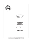
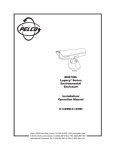
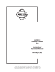
WARNING!
Warning! When lifting, transporting, or unpacking the PT7700 Series pan/tilt systems,
DO NOT use the camera enclosure as a
handle. Severe damage to the unit can occur.
C997M
®
3500 Pelco Way, Clovis, CA 93612-5699 • (559) 292-1981 • (800) 289-9100
• FAX (800) 289-9150
®
PT7700 Series
Pan and Tilt
Systems
Installation/
Operation Manual
C397M (4/98)
Pelco • 3500 Pelco Way • Clovis, CA 93612-5699 • USA • www.pelco.com
In North America and Canada: Tel (800) 289-9100 • FAX (800) 289-9150
International Customers: Tel (1-559) 292-1981 or FAX (1-559) 348-1120
Pelco Manual C397M (4/98)
1
CONTENTS
Section
Page
1.0 GENERAL .................................................................................................. 3
1.1 IMPORTANT SAFEGUARDS AND WARNINGS ............................... 3
2.0 DESCRIPTION .......................................................................................... 4
2.1 MODELS ............................................................................................ 4
2.2 CERTIFICATIONS ............................................................................. 4
3.0 INSTALLATION .......................................................................................... 5
3.1 MOUNTING ....................................................................................... 5
3.2 CAMERA/LENS INSTALLATION ....................................................... 5
3.3 WIRING ............................................................................................. 7
3.4 TESTING SYSTEM AND ADJUSTING LIMIT STOPS ...................... 10
4.0 OPERATION ............................................................................................. 11
5.0 TROUBLESHOOTING .............................................................................. 12
6.0 MAINTENANCE ........................................................................................ 13
7.0 EXPLODED ASSEMBLY DIAGRAMS ...................................................... 15
8.0 SPECIFICATIONS .................................................................................... 20
9.0 WARRANTY AND RETURN INFORMATION ........................................... 24
LIST OF ILLUSTRATIONS
Figure
1
2
3
4
5
6
7
8
9
10
11
Page
PT7700 Series Input Wiring Diagram ................................................ 8
PT7700 Series Connector ................................................................. 9
Tilt Limit Stop Adjustment ................................................................. 10
Pan Adjustments and Lubrication ..................................................... 14
Tilt Adjustments and Lubrication ....................................................... 14
Exploded Assembly Diagram for Blower and Circuit Board .............. 15
Exploded Assembly Diagram for Heaters and Circuit Board ............ 17
Wiring Diagram for Enclosure Circuit Board ..................................... 18
Component Locations for Enclosure Circuit Board ........................... 19
Layout of Traces on Enclosure Circuit Board ................................... 19
Dimension Drawing ........................................................................... 23
LIST OF TABLES
Table
A
B
Page
Parts List (Figure 6) .......................................................................... 16
Parts List (Figure 7) .......................................................................... 17
REVISION HISTORY
Manual #
C397M
C397M
Date
8/96
8/97
4/98
2
Comments
Original version
Completely revised manual. Added models and revised
pin assignments in Figure 2 per ECR #0927.
Removed options. Added certifications. Changed pagination.
Pelco Manual C397M (4/98)
1.0 GENERAL
1.1 IMPORTANT SAFEGUARDS AND WARNINGS
Prior to installation and use of this product, the following WARNINGS should be
observed.
1.
Installation and servicing should only be done by Qualified Service Personnel
and conform to all Local codes.
2.
Unless the unit is specifically marked as a NEMA Type 3, 3R, 3S, 4, 4X, 6, or
6P enclosure, it is designed for indoor use only and it must not be installed
where exposed to rain and moisture.
3.
The weight of the camera/lens and enclosure shall not exceed 75 lbs.
(34.02 kg).
4.
Only use replacement parts recommended by Pelco.
5.
After replacement/repair of this unit’s electrical components, conduct a resistance measurement between line and exposed parts to verify the exposed
parts have not been connected to line circuitry.
6.
The installation method and materials should be capable of supporting four
(4) times the weight of the enclosure, pan/tilt, camera and lens combination.
The product and/or manual may bear the following marks:
This symbol indicates that dangerous voltage constituting a
risk of electric shock is present within this unit.
This symbol indicates that there are important operating and
maintenance instructions in the literature accompanying this
unit.
CAUTION:
RISK OF
ELECTRIC SHOCK.
DO NOT OPEN.
CAUTION:
TO REDUCE THE RISK OF ELECTRICAL SHOCK,
DO NOT REMOVE COVER. NO USERSERVICEABLE PARTS INSIDE. REFER SERVICING
TO QUALIFIED SERVICE PERSONNEL.
Please thoroughly familiarize yourself with the information
in this manual prior to installation and operation.
Pelco Manual C397M (4/98)
3
2.0 DESCRIPTION
The PT7700 systems combine an environmental camera enclosure, pan/tilt assembly, and receiver/driver into a single unit that you can install indoors or outdoors. You can install 2/3-inch (1.69 cm) and 1-inch (2.54 cm) format cameras with
either fixed focal length lenses or motorized zoom lenses. An adjustable camera
sled will accommodate different sizes of cameras and lenses.
2.1 MODELS
PT7723RX-1
PT7723RX-1/PP
PT7723RX-3
PT7723RX-3/PP
PT7729RX
PT7729RX-1
PT7729RX-1/PP
PT7729RX-1/SL
PT7729RX-3
PT7729RX-3/PP
PT7723WX-1
PT7729WX
PT7729WX-1
PT7729WX-3
Pan/tilt, CX9115RX Coaxitron® receiver/driver, and EH5723-1
23-inch (54 cm) enclosure. 120 VAC input. Thermostatically
controlled heater and blower.
PT7723RX-1 with preset positioning capabilities and alarm
outputs.
Pan/tilt, CX9115RX Coaxitron® receiver/driver, and EH5723-1
23-inch (54 cm) enclosure. 230VAC input. Thermostatically
controlled heater and blower.
PT7723RX-3 with preset positioning capabilities and alarm
outputs.
Pan/tilt, CX9115RX Coaxitron® receiver/driver, and EH5729
29-inch (74 cm) environmental camera enclosure. 120 VAC input.
PT7729RX with thermostatically controlled heater and blower.
PT7729RX-1 with preset positioning capabilities and alarm
outputs.
PT7729RX-1 with 360° pan rotation.
Pan/tilt, CX9220RX Coaxitron® receiver/driver, and EH5729-3
29-inch (74 cm) enclosure. 230 VAC input. Thermostatically
controlled heater and blower.
PT7729RX-3 with preset positioning capabilities and alarm
outputs.
Pan/tilt, WX8115RX Wiretron receiver/driver, and EH5723-1
23-inch (54 cm) enclosure. 120 VAC input. Thermostatically
controlled heater and blower.
Pan/tilt, WX8115RX Wiretron receiver/driver, and EH5729
29-inch (74 cm) environmental camera enclosure. 120 VAC input.
PT7729WX with thermostatically controlled heater and blower.
Pan/tilt, WX8220RX Wiretron receiver/driver, and EH5729-3
29-inch (74 cm) enclosure. 230 VAC input. Thermostatically
controlled heater and blower.
2.2 CERTIFICATIONS
The products identified below have been tested and certified for agency compliance as noted.
Model
PT7723RX-1
PT7723RX-1/PP
PT7729RX-1
PT7729RX-1/PP
PT7729RX-1/SL
PT7723WX-1
PT7729WX
PT7729WX-1
CE
Agency Compliance Certification
FCC
UL
CSA/cUL
X
X
X
X
X
X
X
X
Applicable CE, FCC, UL, and CSA/cUL directives/standards:
•
4
UL Listed to UL2044
Pelco Manual C397M (4/98)
3.0 INSTALLATION
CAUTION: When unpacking, transporting, or lifting the PT7700 Series systems, DO NOT use
the camera enclosure as a handle. Severe damage to the unit can occur.
NOTE: To insure proper wiring and operation of your equipment, it is recommended that you test the PT7700
system and its controller in your facility before installing them in the field. Refer to Sections 3.2 through 3.4.
3.1 MOUNTING
CAUTION: The PT7700
systems are designed to operate in an upright position
only. Do not mount the systems horizontally or in an inverted position.
Attach the base of the pan/tilt system to a flat surface. If you use a wall or pedestal
mount, follow the instructions that are provided with the mount.
Make sure the mounting surface can support four (4) times the weight of the pan/tilt
system. Refer to section 8.0, “Specifications,” for unit weights (excluding camera/
lens).
Proceed to Section 3.2, CAMERA/LENS INSTALLATION.
3.2 CAMERA/LENS INSTALLATION
1.
2.
Open the enclosure lid and remove the camera sled from the rail:
a.
Loosen the screws.
b.
Slide the sled so that the screws are in the large part of the mounting
slots.
c.
Remove the sled.
d.
Remove the parts tied to the sled.
All Models Except the PT7729RX and PT7729WX - If you are installing the
pan/tilt system in a marine or high-moisture environment, make the following
modifications to your enclosure:
Refer to Figure 6 in Section 7.0, “Exploded Assembly Diagram,” for an exploded assembly diagram of the blower assembly.
Pelco Manual C397M (4/98)
a.
Remove the plastic cover over the power supply section of the circuit
board.
b.
Disconnect the electrical plug from the fan.
c.
Remove the three screws that secure the fan plate and fan to the enclosure.
d.
Remove the four screws that secure the fan to the fan plate.
e.
Turn the fan around so that it blows toward the viewing window (refer to
the arrows on the fan).
f.
Reinstall the fan on the fan plate.
g.
Reinstall the fan plate and fan in the enclosure.
h.
Reconnect the electrical plug on the fan.
i.
Replace the plastic cover.
5
NOTE: If the AC power input to your
j.
On the bottom of the enclosure, remove the vent grill and filters at the
front of the enclosure. Replace the grill with one of the vent cover plates
that was attached to the camera sled as loose equipment.
k.
On the bottom of the enclosure, attach the other vent cover plate over
the grill at the rear of the enclosure.
3.
Mount the camera/lens to the sled with the 1/4-20 Phillips-head screws that
are provided in the parts bag. You can mount the camera to either side of the
sled for proper elevation of the camera inside the enclosure.
4.
Install the sled and camera/lens in the enclosure:
a.
If the camera’s lens is adjustable, extend the lens to its maximum length.
b.
Place the sled over the mounting screws in the enclosure.
c.
Slide the sled forward until the camera’s lens almost touches the window.
d.
Tighten the screws to secure the camera sled to the enclosure.
5.
Connect the video cable in the enclosure to the video output connection on
the camera.
6.
If your camera has a motorized zoom lens control, connect or wire the camera’s
lens control to the LENS or LENS CONTROL connector on the circuit board.
Refer to Figure 1 to see where to connect different lens connector options.
7.
Wire power from the circuit board to the camera. There are two ways to connect power (refer to Figure 1):
PT7700 unit is 120 VAC, the camera
must use 120 VAC. If the power input is 230 VAC, the camera must use
230 VAC.
a.
A three-pin plug with leads is supplied as loose equipment. Connect the
leads from the plug to the camera as follows:
Brown - AC HI
Blue - AC NT
Green - Ground
Remove the plastic cover over the power supply section of the circuit
board.
Connect the plug to the CAM1 socket on the circuit board.
Replace the plastic cover.
or
b.
If your pan/tilt system uses 120 VAC and you ordered the optional 120 VAC
electrical outlet accessory (O/I-OUTLET), connect the 120 VAC plug to the
camera. Connect the three-pin plug to CAM1 (remove the plastic cover over
the circuit board and replace the cover after you plug in the connector).
8.
Adjust the focus and iris on the camera, if necessary.
9.
Close the enclosure lid.
Proceed to Section 3.3, WIRING.
6
Pelco Manual C397M (4/98)
3.3 WIRING
1.
Route the six-foot power/video/control cable through the wall or pedestal mount
if applicable.
2.
Connect the end of the cable with the 16-pin connector to the mating connector in the base of the pan/tilt unit.
3.
Connect the other end of the cable as follows:
a.
Connect the coax cable to the video input of the controller.
b.
For models PT7729WX, PT7729WX-1, PT7723WX-1 and PT7729WX-3,
connect the Wiretron control wires (refer to Figure 2).
c.
For models PT7729RX-1/PP and PT7729RX-3/PP, connect the alarm
outputs (cable not supplied). Refer to Figure 2.
d.
Plug the power cord into either 120 VAC or 230 VAC, depending on your
model.
Proceed to Section 3.4, TESTING SYSTEM AND ADJUSTING LIMIT STOPS.
Pelco Manual C397M (4/98)
7
Figure 1. PT7700 Series Input Wiring Diagram
8
Pelco Manual C397M (4/98)
PIN
PT7729RX
PT7723RX-1
PT7729RX-1
PT7729RX-3
PT7729RX-1/SL
Base Connector
Pin Assignments
FUNCTION
2
COAX CORE
4
COAX SHIELD
BLK
8
GROUND
GRN
10
AUX COMMON
WHT/GRN
11
AUX1
ORG
AUX2
YEL
13
AUX3
BLU
15
AC NEUTRAL
WHT (2X)
16
AC HIGH
BLK (2X)
FUNCTION
PT7729RX-1/PP
PT7729RX-3/PP
With Alarm Outputs
Base Connector
Pin Assignments
COLOR
2
COAX CORE
4
COAX SHIELD
BLK
8
GROUND
GRN
RED
BRN/WHT
9
WIRETON INPUT SIGNAL HIGH
10
AUX COMMON
WHT/GRN
11
AUX1
ORG
12
AUX2
YEL
13
AUX3
BLU
14
WIRETRON INPUT SIGNAL LOW
BLK/WHT
15
AC NEUTRAL
WHT (2X)
16
AC HIGH
BLK (2X)
PIN
2
RED
12
PIN
PT7729WX
PT7723WX-1
PT7729WX-1
PT7729WX-3
Base Connector
Pin Assignments
COLOR
FUNCTION
COAX CORE
COLOR
RED
4
COAX SHIELD
BLK
8
GROUND
GRN
15
AC NEUTRAL
WHT (2X)
16
AC HIGH
BLK (2X)
1
ALARM #1
3
ALARM #2
5
ALARM #3
6
ALARM #4
7
ALARM #5
10
ALARM #6
11
ALARM #7
12
ALARM #8
13
EXTERNAL ALARMING OUTPUT (ACTIVE LO)
ALARM COMMON IS CHASSIS GROUND
Figure 2. PT7700 Series Connector
Pelco Manual C397M (4/98)
9
3.4 TESTING SYSTEM AND ADJUSTING LIMIT STOPS
WARNING: Never remove
the limit stops. Do not adjust the limit stops while the
unit is moving. You may injure yourself or damage the
unit.
NOTE: The tilt limit stops are factory
set for 0° and -90° from the horizon.
To test the system and adjust the limit stops:
1.
Loosen the two pan limit stops at the base of the pan/tilt.
2.
Turn on power.
3.
Test the system by moving the pan/tilt to the left, right, up and down. Do not
move the pan/tilt very far as the limit stops are not set yet. All you want to do is
verify that the motors work. Also verify that the camera functions properly.
4.
Pan the unit to the right to the desired right pan limit.
5.
Move the right pan limit stop until it touches the pan limit switch actuator.
Continue pushing the stop until the actuator clicks, indicating the switch has
opened. Lock the stop in place.
6.
Pan the unit to the left to the desired left pan limit.
7.
Move the left pan limit stop until it touches the pan limit switch actuator. Continue pushing the stop until the actuator clicks, indicating the switch has opened.
Lock the stop in place.
8.
Remove the four screws from the right side cover of the pan/tilt.
9.
Refer to Figure 3 and loosen the recessed set screws on the up and down
limit stop collars attached to the tilt shaft.
10. Tilt the unit up to the desired upward limit.
11. Turn the up limit stop collar until it touches the tilt limit switch actuator. Continue turning the stop until the actuator clicks, indicating the switch has opened.
Lock the collar in place.
12. Tilt the unit down to the desired downward limit.
13. Turn the down limit stop collar until it touches the tilt limit switch actuator.
Continue turning the stop until the actuator clicks, indicating the switch has
opened. Lock the collar in place.
14. Replace the side cover.
15. The installation is complete.
Figure 3. Tilt Limit Stop Adjustment
10
Pelco Manual C397M (4/98)
4.0 OPERATION
Refer to the manual for your control equipment for operating the pan/tilt system.
If your enclosure has a thermostatically controlled blower, the thermostat is set to
turn the fan on between 77° and 93°F (25° and 34°C) and to turn the fan off between 62° and 78°F (17° and 26°C).
If your enclosure has thermostatically controlled heaters or defroster, the thermostat is set to turn them on between 42° and 58°F (6° and 14°C) and to turn them off
between 72° and 88°F (22° and 31°C).
Pelco Manual C397M (4/98)
11
5.0 TROUBLESHOOTING
Fuses are located inside the left cover of the pan/tilt unit. Fuses F1 (mother board)
and F2 (camera) are 2/10-ampere, slow-blow fuses. F3 (pan/tilt) is a 1-ampere,
slow-blow fuse. To order fuses F1 and F2, specify the part number FUS2/10SB. To
order fuse F3, specify the part number FUS1SB.
If you need to return the pan/tilt system and you can not place the camera enclosure in a horizontal position, remove three of the four Allen bolts that attach the
enclosure to the tilt shaft. This will allow movement without damage to the gear
train assembly components.
Figures 6-7 and Tables A-B show exploded assembly diagrams and parts lists for
the blower and heaters, if your model is equipped with them.
Figures 8-10 show the wiring, component locations, and layout of traces for the
circuit board in the enclosure.
12
Pelco Manual C397M (4/98)
6.0 MAINTENANCE
Perform the following maintenance at six-month (or more often in harsh environments) intervals to prolong the operational life and appearance of the equipment.
Window and Filters
1.
Clean the window with a mild nonabrasive detergent in water and a soft cloth
to maintain picture clarity.
2.
If your enclosure has a blower, clean the foam filters as follows:
a.
On the bottom front of the enclosure, remove the two screws in the vent grill.
b.
Remove the vent grill and take out the filters.
c.
Clean the filters with warm water and mild detergent, dry thoroughly, and
replace them in the grill.
d.
Reinstall the vent grill.
To order replacement filters, use the part number EH550010045.
Pan Adjustments and Lubrication
3.
Tilt the enclosure so that the front points downward.
4.
Remove the four screws at the rear, just above the base, of the pan/tilt unit.
5.
Lift up the lid slightly and push it forward to free the lip at the front of the lid.
6.
Check the tension of the pan drive chain. A movement of 1/32" to 3/32" in the
chain is acceptable. To adjust the chain:
Refer to Figure 4. Loosen the four screws (A - two shown) that secure the
motor/gearbox to the mounting frame.
b.
Use a screwdriver to pry at B to apply tension to the chain.
c.
Tighten the screws.
7.
If necessary, tighten the nut at C to remove any endplay in the worm (E).
8.
Lubricate the pan gears and chain assembly with a high quality grease capable of withstanding temperatures from -50° to 170° F (-46° to 77° C):
9.
Pelco Manual C397M (4/98)
a.
a.
Liberally apply grease to the chain and sprockets (D), worm (E), and
worm gear (behind worm).
b.
Pan the unit to spread the grease uniformly on the parts.
c.
Apply additional grease if necessary.
Replace the lid over the pan housing.
13
Tilt Adjustments and Lubrication
10. Remove the plastic cover on the right side of the pan/tilt unit.
11. Refer to Figure 5. Verify that the worm (B) is fully seated in the worm gear (A).
If it is not, turn the two nuts (C) to lift the worm. Tighten the two nuts at (D).
12. If necessary, tighten the nut at E to remove any endplay in the worm (B).
13. If you can move the enclosure up and down, but the worm gear (A) does not
move, push pin H further into the tilt shaft to eliminate movement.
14. Lubricate the tilt gears and chain assembly with a high quality grease capable
of withstanding temperatures from -50° to 170° F (-46° to 77° C):
a.
Liberally apply grease to the chain and sprockets (J), worm (B), and worm
gear (A).
b.
Tilt the unit to spread the grease uniformly on the parts.
c.
Apply additional grease if necessary.
15. Replace the cover over the tilt housing.
Figure 4. Pan Adjustments and Lubrication
H
A
E
D
C
G
B
F
C
D
J
Figures 5. Tilt Adjustments and Lubrication
14
Pelco Manual C397M (4/98)
7.0 EXPLODED ASSEMBLY DIAGRAMS
B
11
C
9
E
10
B
C
A B
8
B
12
A
F
G
7
H
6
5
4
2
1
SCREWS COME WITH
BLANKING PLATE
Figure 6. Exploded Assembly Diagram for Blower and Circuit Board
Pelco Manual C397M (4/98)
15
Table A. Parts List (Figure 6)
16
Item
Qty
Description
Part Number
1
2
4
5
6
7
8
9
10
11
12
1
2
1
1
2
1
1
1
1
1
1
1
Vent Grill
Foam Filter
Circuit Board Insulator
Circuit Board
Power Supply Barrier
Power Supply Barrier Cover
Fan Wire Cord with Plug
Fan Tube, 230 VAC
Fan Tube, 120 VAC
Fan Plate
Standoff, 3.375" Length
Connector Plug
57004005COMP
EH550010045
EH450010256
PCB9000276ASSY
EH47004029COMP
EH470010019
WIR432000
ED210015
EH18013
57004010COMP
570010007
CON1-480318-0
A
B
C
E
F
G
H
3
8
2
4
2
2
2
Screw, 6-32 x 3/8", Pan Head, Phillips
Internal Tooth Lock Washer, #6
Flat Washer, #6
Cap Screw, 6-32 x 3/8", Allen Socket Head
Screw, 4-40 x 1/4", Pan Head, Phillips
Split Lock Washer, #4
Circuit Board Grounding Clip
ZH6-32X.375SPP
ZH6LWSIS
ZH148X375X32
ZH6-32X.375CS
ZH4-40X.250SPP
ZH4LWSSL
570010004
Pelco Manual C397M (4/98)
Figure 7. Exploded Assembly Diagram for Heaters and Circuit Board
Table B. Parts List (Figure 7)
Item
Qty
1
2
1
2
2
1
1
2
1
1
Bracket/Heater Sink
Heater, 230 VAC
Heater, 120 VAC
Connector Plug
Power Supply Barrier Cover
Power Supply Barrier
Circuit Board
Circuit Board Insulator
57004020COMP
HTR40220
HTR50120
CON1-480424-0
EH470010019
EH47004029COMP
PCB9000276ASSY
EH450010256
2
4
2
4
2
2
2
2
Spacer, .375" Length
Internal Tooth Lock Washer, #4
Internal Tooth Lock Washer, #4
Screw 4-40 x 1/4", Pan Head, Phillips
Screw 4-40 x 1/4", Pan Head, Phillips
Grounding Clip
Screw, 6-32 x 1/4", Pan Head, Phillips
Internal Star Washer, #6
SPA8422
ZH4LWSIS
ZH4LWSIS
ZH4-40X.250SPP
ZH4-40X.250SPP
570010004
ZH6-32X.250SPP
ZH6LWSIS
3
4
5
6
7
A
B
C
D
E
F
Pelco Manual C397M (4/98)
Description
Part Number
17
Figure 8. Wiring Diagram for Enclosure Circuit Board
18
Pelco Manual C397M (4/98)
Figure 9. Component Locations for Enclosure Circuit Board
Figure 10. Layout of Traces on Enclosure Circuit Board
Pelco Manual C397M (4/98)
19
8.0 SPECIFICATIONS
SYSTEM
Input Voltage:
120 or 230 VAC, 50/60 Hz
Power Requirements:
PT7729RX,
PT7729WX
0.35 A (42 vA)
PT7729RX-1,
PT7723RX-1,
PT7729RX-1/PP,
PT7729RX-1/SL,
PT7729WX-1,
PT7723WX-1
1.7 A (204 vA)
PT7729RX-3,
PT7729RX-3/PP,
PT7729WX-3
1.9 A (437 vA)
Power/Control Cables
All Models:
Power - 3-wire grounded, 18 AWG, 6 ft (1.83 m)
Video - RG59, 6 ft (1.83 m)
PT7729WX,
PT7729WX-1,
PT7723WX-1,
PT7729WX-3
Wiretron Control - 2-conductor, 18 AWG, 6 ft (1.83 m)
NEMA Rating:
3R
Environment:
Indoor/outdoor -10° to 120° F (-23° to 49° C)
Dimensions:
See Figure 11
Unit Weight
PT7723RX-1,
PT7723WX-1
48 lbs (21.77 kg)
PT7729RX,
PT7729WX
49 lbs (22.23 kg)
PT7729RX-1,
PT7729RX-1/PP,
PT7729RX-3,
PT7729RX-3/PP,
PT7729RX-1/SL,
PT7729WX-1,
PT7729WX-3
53 lbs (24.04 kg)
20
Pelco Manual C397M (4/98)
PAN/TILT
Construction
Body:
Side Covers:
Aluminum plate
Vacuum-formed ABS plastic, UV protected
Pan:
0-355° movement in horizontal plane, except PT7729RX-1/SL,
which has 360° pan rotation
Pan Speed:
9°/sec ±1° (no load condition)
Tilt:
+15° movement in vertical plane from horizon
-90° movement in vertical plane from horizon
Tilt Speed:
3°/sec ±5° (no load condition)
Torque
Pan:
Tilt:
10 ft lbs with specified voltage
20 ft lbs with specified voltage
Gearing:
Adjustable worm-gear final drive to prevent drift and minimize
backlash
Bearings:
Heavy-duty ball bearings on all rotating surfaces
Motors:
Instantaneous reversing
Limit Switches:
Pan and tilt - 5 A each
RECEIVER/DRIVER
Coaxitron® Receiver/Driver
Fuses:
One 1 A, 3 AG type
Two 2/10 A, 3 AG type
Control Method:
15-pulse train (pulse width modulated) superimposed on the
video signal during the vertical interval by the control transmitter. Pulse train occupies one (1) TV line period.
Pulse Amplitude:
Approximately 1 V p-p added to video signal; 333 KHz nominal
Input Video:
1 V p-p nominal; 2 V p-p maximum at less than 75% APL; 1.5
V p-p maximum at 90% APL
System Bandwidth: Less than 2 dB down at 10 MHz (exclusive of cable)
Maximum Operating
Distance:
750 ft (229 m) on RG59
1000 ft (305 m) on RG6
1500 ft (457 m) on RG1
(cables above are 75-ohm coax)
Pelco Manual C397M (4/98)
21
Wiretron Receiver/Driver
Fuses:
One 1 A, 3 AG type
Two 2/10 A, 3 AG type
Control Method:
15 pulse train (pulse width modulated)
Pulse Amplitude:
35 mA current loop
Cable
Requirements:
Twisted pair, unshielded
Operating Distance: 22 AWG - 5 miles (8 km)
20 AWG - 10 miles (16 km)
ENCLOSURE
Construction:
Aluminum
Finish:
Gray polyester powder coat
Window:
Glass, 0.25-inch (0.64 cm) thick
Window Viewing
Area:
3.8" H x 4.8" W (9.65 x 12.19 cm)
Camera Mounting: Removable camera than can be inverted to accommodate
various heights of cameras and lenses
Maximum
Camera/Lens Size:
EH5723
EH5723-1,-2,-3
EH5729
EH5729-1,-2,-3
Electrical
Connections:
Accessory
Input Power:
22" L x 7.5" W x 5.5" H (55.88 x 19.05 x 13.97 cm)
15.5" L x 6.25" W x 5.5" H (39.37 x 15.88 x 13.97 cm)
28" L x 7.5" W x 5.5" H (71.12 x 19.05 x 13.97 cm)
21.5" L x 6.25 W x 5.5" H (54.61 x 15.88 x 13.97 cm)
One each of the following:
3-connector terminal block for power input
6-pin lens connector
9-connector terminal block for lens wiring
10-connector terminal block for camera/lens wiring
3-pin socket for camera power input
2-pin socket for blower
2-pin socket for defroster
4-pin socket for heaters
4-pin socket for wiper
2-pin socket for wiper control
BNC for video
Heater (120 VAC models)
Heater (230 VAC models)
Defroster (all models)
Blower (all models)
Wiper (all models)
90 watts
70 watts
30 watts
15 watts
15 watts
(Design and product specifications subject to change without notice.)
This equipment contains electrical or electronic components that must be recycled properly to comply with Directive 2002/96/EC of the European Union
regarding the disposal of waste electrical and electronic equipment (WEEE). Contact your local dealer for procedures for recycling this equipment.
22
Pelco Manual C397M (4/98)
MODEL
“A”
“B”
PT7729RX
PT7729RX-1
PT7729RX-1/SL
PT7729RX-1/PP
PT7729RX-3
PT7729RX-3/PP
PT7729WX
PT7729WX-1
PT7729WX-3
32.50 (82.55)
29.00 (73.66)
PT7723RX-1
PT7723RX-1/PP
PT7723RX-3
PT7723RX-3/PP
PT7723WX-1
26.50 (67.31)
23.00 (58.42)
Figure 11. Dimension Drawing
Pelco Manual C397M (4/98)
23
9.0 WARRANTY AND RETURN INFORMATION
WARRANTY
Pelco will repair or replace, without charge, any merchandise proved defective in material or
workmanship for a period of one year after the date of shipment.
Exceptions to this warranty are as noted below:
• Five years on FT/FR8000 Series fiber optic products.
• Three years on Genex® Series products (multiplexers, server, and keyboard).
• Three years on Camclosure® and fixed camera models, except the CC3701H-2, CC3701H-2X,
CC3751H-2, CC3651H-2X, MC3651H-2, and MC3651H-2X camera models, which have a fiveyear warranty.
• Two years on standard motorized or fixed focal length lenses.
• Two years on Legacy®, CM6700/CM6800/CM9700 Series matrix, and DF5/DF8 Series fixed
dome products.
• Two years on Spectra®, Esprit®, ExSite™, and PS20 scanners, including when used in
continuous motion applications.
• Two years on Esprit® and WW5700 Series window wiper (excluding wiper blades).
• Eighteen months on DX Series digital video recorders, NVR300 Series network video
recorders, and Endura ™ Series distributed network-based video products.
• One year (except video heads) on video cassette recorders (VCRs). Video heads will be
covered for a period of six months.
• Six months on all pan and tilts, scanners or preset lenses used in continuous motion applications
(that is, preset scan, tour and auto scan modes).
Pelco will warrant all replacement parts and repairs for 90 days from the date of Pelco shipment.
All goods requiring warranty repair shall be sent freight prepaid to Pelco, Clovis, California. Repairs
made necessary by reason of misuse, alteration, normal wear, or accident are not covered under
this warranty.
Pelco assumes no risk and shall be subject to no liability for damages or loss resulting from the
specific use or application made of the Products. Pelco’s liability for any claim, whether based on
breach of contract, negligence, infringement of any rights of any party or product liability, relating
to the Products shall not exceed the price paid by the Dealer to Pelco for such Products. In no event
will Pelco be liable for any special, incidental or consequential damages (including loss of use, loss
of profit and claims of third parties) however caused, whether by the negligence of Pelco or
otherwise.
The above warranty provides the Dealer with specific legal rights. The Dealer may also have
additional rights, which are subject to variation from state to state.
If a warranty repair is required, the Dealer must contact Pelco at (800) 289-9100 or (559) 292-1981
to obtain a Repair Authorization number (RA), and provide the following information:
1. Model and serial number
2. Date of shipment, P.O. number, Sales Order number, or Pelco invoice number
3. Details of the defect or problem
If there is a dispute regarding the warranty of a product which does not fall under the warranty
conditions stated above, please include a written explanation with the product when returned.
Method of return shipment shall be the same or equal to the method by which the item was received
by Pelco.
RETURNS
Pelco, the Pelco logo, Camclosure, Esprit,
Genex, Legacy, and Spectra are registered
trademarks of Pelco.
Endura and ExSite are trademarks of Pelco.
© Copyright 1998, Pelco. All rights reserved.
24
In order to expedite parts returned to the factory for repair or credit, please call the factory at (800)
289-9100 or (559) 292-1981 to obtain an authorization number (CA number if returned for credit,
and RA number if returned for repair).
All merchandise returned for credit may be subject to a 20% restocking and refurbishing charge.
Goods returned for repair or credit should be clearly identified with the assigned CA or RA number
and freight should be prepaid. Ship to the appropriate address below.
If you are located within the continental U.S., Alaska, Hawaii or Puerto Rico, send goods to:
Service Department
Pelco
3500 Pelco Way
Clovis, CA 93612-5699
If you are located outside the continental U.S., Alaska, Hawaii or Puerto Rico and are instructed
to return goods to the USA, you may do one of the following:
If the goods are to be sent by a COURIER SERVICE, send the goods to:
Pelco
3500 Pelco Way
Clovis, CA 93612-5699 USA
If the goods are to be sent by a FREIGHT FORWARDER, send the goods to:
Pelco c/o Expeditors
473 Eccles Avenue
South San Francisco, CA 94080 USA
Phone: 650-737-1700
Fax: 650-737-0933
Pelco Manual C397M (4/98)