1
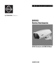
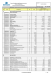
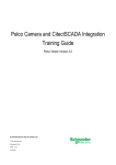
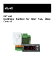
I N S T A L L A T I O N
EH1512 Series
Enclosures
EH1512 Enclosure with EM1512 Mount
C3453M-C (5/09)
Contents
Important Safety Instructions . . . . . . . . . . . . . . . . . . . . . . . . . . . . . . . . . . . . . . . . . . . . . . . . . . . . . . . . . . . . . . . . . . . . . . . . . . . . . . . . . . . . . . . . . . . . 3
Description. . . . . . . . . . . . . . . . . . . . . . . . . . . . . . . . . . . . . . . . . . . . . . . . . . . . . . . . . . . . . . . . . . . . . . . . . . . . . . . . . . . . . . . . . . . . . . . . . . . . . . . . . . . 4
Models . . . . . . . . . . . . . . . . . . . . . . . . . . . . . . . . . . . . . . . . . . . . . . . . . . . . . . . . . . . . . . . . . . . . . . . . . . . . . . . . . . . . . . . . . . . . . . . . . . . . . . . . . 4
Optional Accessories . . . . . . . . . . . . . . . . . . . . . . . . . . . . . . . . . . . . . . . . . . . . . . . . . . . . . . . . . . . . . . . . . . . . . . . . . . . . . . . . . . . . . . . . . . . . . . 5
Package Contents . . . . . . . . . . . . . . . . . . . . . . . . . . . . . . . . . . . . . . . . . . . . . . . . . . . . . . . . . . . . . . . . . . . . . . . . . . . . . . . . . . . . . . . . . . . . . . . . . 6
Installation . . . . . . . . . . . . . . . . . . . . . . . . . . . . . . . . . . . . . . . . . . . . . . . . . . . . . . . . . . . . . . . . . . . . . . . . . . . . . . . . . . . . . . . . . . . . . . . . . . . . . . . . . . . 7
Installing the Optional Security Kit. . . . . . . . . . . . . . . . . . . . . . . . . . . . . . . . . . . . . . . . . . . . . . . . . . . . . . . . . . . . . . . . . . . . . . . . . . . . . . . . . . . . 7
Installing the Camera and Mount. . . . . . . . . . . . . . . . . . . . . . . . . . . . . . . . . . . . . . . . . . . . . . . . . . . . . . . . . . . . . . . . . . . . . . . . . . . . . . . . . . . . . 7
Installing the Sun Shroud . . . . . . . . . . . . . . . . . . . . . . . . . . . . . . . . . . . . . . . . . . . . . . . . . . . . . . . . . . . . . . . . . . . . . . . . . . . . . . . . . . . . . . . . . . 11
Maintenance . . . . . . . . . . . . . . . . . . . . . . . . . . . . . . . . . . . . . . . . . . . . . . . . . . . . . . . . . . . . . . . . . . . . . . . . . . . . . . . . . . . . . . . . . . . . . . . . . . . . . . . . 12
Specifications . . . . . . . . . . . . . . . . . . . . . . . . . . . . . . . . . . . . . . . . . . . . . . . . . . . . . . . . . . . . . . . . . . . . . . . . . . . . . . . . . . . . . . . . . . . . . . . . . . . . . . . 13
2
C3453M-C (5/09)
Important Safety Instructions
1. Read these instructions.
2. Keep these instructions.
3. Heed all warnings.
4. Follow all instructions.
5. Do not use this apparatus near water.
6. Clean only with dry cloth.
7. Do not block any ventilation openings. Install in accordance with the manufacturer’s instructions.
8. Do not install near any heat sources such as radiators, heat registers, stoves, or other apparatus (including amplifiers) that produce heat.
9. Do not defeat the safety purpose of the polarized or grounding-type plug. A polarized plug has two blades with one blade wider than the
other. A grounding plug has two blades and a third grounding prong. The wide blade or the third prong are provided for your safety. If the
provided plug does not fit into your outlet, consult an electrician for replacement of the obsolete outlet.
10. Protect the power cord from being walked on or pinched particularly at plugs, convenience receptacles, and the points where they exit from
the apparatus.
11. Only use attachments/accessories specified by the manufacturer.
12. Only use with the cart, stand, tripod, bracket, or table specified by the manufacturer, or sold with the apparatus. When a cart is used, use
caution when moving the cart/apparatus combination to avoid injury from tip-over.
13. Refer all servicing to qualified service personnel. Servicing is required when the apparatus has been damaged in any way, such as powersupply cord or plug is damaged, liquid has been spilled or objects have fallen into the apparatus, the apparatus has been exposed to rain or
moisture, does not operate normally, or has been dropped.
14. Unplug the apparatus during lightning storms or when unused for long periods of time.
15. Apparatus shall not be exposed to dripping or splashing and no objects filled with liquids, such as vases shall be placed on the apparatus.
16. WARNING: To reduce the risk of fire or electric shock, do not expose this apparatus to rain or moisture.
17. Installation should be done only by qualified personnel and conform to all local codes.
18. Unless this unit is specifically marked as NEMA Type 3, 3R, 3S, 4, 4X, 6, or 6P enclosure, it is designed for indoor use only and it must not
be installed where exposed to rain and moisture.
19. Only use installation methods and materials capable of supporting four times the maximum specified load.
20. Only use replacement parts recommended by Pelco.
21. Do not use attachments, such as mounts, that are not recommended by Pelco. They may be hazardous.
22. A CCC-approved power cord must be used to power this equipment when used in China.
The product and/or manual may bear the following marks:
This symbol indicates that dangerous voltage constituting a risk of electric shock is
present within this unit.
This symbol indicates that there are important operating and maintenance instructions in
the literature accompanying this unit
C3453M-C (5/09)
CAUTION:
RISK OF ELECTRIC SHOCK.
DO NOT OPEN.
3
Description
The EH1512 Series indoor/outdoor enclosures are designed for use with small- to medium-sized analog and IP cameras. They will accommodate
both fixed and variable focal length lenses (with or without auto-iris operation). They can be wall mounted using either Pelco’s EM1512
(feedthrough wall mount) or any light to medium duty mount.
The tethered, removable enclosure lid provides easy access during installation and when camera and lens adjustments are necessary. Power and
video cabling is brought into the enclosure through two adjustable glands (PG9 and PG11) on the bottom of the enclosure, allowing for easy
installation.
Field-installed options include a heater/blower or blower with a 24 VAC camera power supply and sun shroud. The enclosures can also be
ordered from the factory with a 24 VAC, 120 VAC, or 230 VAC heater/blower or blower with a 24 VAC camera power supply. If your enclosure has
a thermostatically controlled heater, the thermostat is set to turn on at 50°F (10°C) and turn off at 80°F (27°C). The blower operates continuously.
An optional security kit that prevents opening the enclosure is available.
NOTE: A metric Allen wrench (5 mm) and a Phillips screwdriver are required for installation but are not included. A flat head screwdriver might
also be needed for all models except the EH1512 and EH1512MT. The Allen wrench is needed to secure the enclosure to all mounts. It is also
needed to open and close the enclosure and to secure the pan/tilt (swivel head) on the EM1512 mount.
MODELS
EH1512
Enclosure, indoor/outdoor.
EH1512MT
Same as EH1512 with an EM1512 feedthrough wall mount.
EH1512-1
Same as EH1512 with a 120 VAC heater/blower with 24 VAC camera power (includes the 4-inch wire tie); 12 W enclosure
power consumption*; 25 W maximum power consumption capacity.
EH1512-2
Same as EH1512 with a 24 VAC heater/blower with 24 VAC camera power; 12 W enclosure power consumption*.
EH1512-3
Same as EH1512 with a 230 VAC heater/blower with 24 VAC camera power (includes the 4-inch wire tie); 12 W enclosure
power consumption*; 25 W maximum power consumption capacity.
EH1512-1MT
Same as EH1512 with a 120 VAC heater/blower with 24 VAC camera power and an EM1512 feedthrough wall mount
(includes the 4-inch wire tie); 12 W enclosure power consumption*; 25 W maximum power consumption capacity.
EH1512-2MT
Same as EH1512 with a 24 VAC heater/blower with 24 VAC camera power and an EM1512 feedthrough wall mount; 12 W
enclosure power consumption*.
EH1512-3MT
Same as EH1512 with a 230 VAC heater/blower with 24 VAC camera power and an EM1512 feedthrough wall mount
(includes the 4-inch wire tie); 12 W enclosure power consumption*; 25 W maximum power consumption capacity.
EH1512-1MTS
Same as EH1512 with a 120 VAC heater/blower with 24 VAC camera power, an EM1512 feedthrough wall mount (includes
the 4-inch wire tie), and an SS1512 sun shroud; 12 W enclosure power consumption*; 25 W maximum power consumption
capacity.
EH1512-2MTS
Same as EH1512 with a 24 VAC heater/blower with 24 VAC camera power, an EM1512 feedthrough wall mount, and an
SS1512 sun shroud; 12 W enclosure power consumption*.
EH1512-3MTS
Same as EH1512 with a 230 VAC heater/blower with 24 VAC camera power, an EM1512 feedthrough wall mount (includes
the 4-inch wire tie), and an SS1512 sun shroud; 12 W enclosure power consumption*; 25 W maximum power consumption
capacity.
*Enclosure power consumption does not include camera wattage.
4
C3453M-C (5/09)
OPTIONAL ACCESSORIES
Blower Kit
EH1512-1BKIT
EH1512-2BKIT
EH1512-3BKIT
Continuous duty, 120 VAC, 1 W, 1.45 cfm
Continuous duty, 24 VAC, 1 W, 1.45 cfm
Continuous duty, 230 VAC, 1 W, 1.45 cfm
Heater/Blower Kit
EH1512-1HBKIT
EH1512-2HBKIT
EH1512-3HBKIT
120 VAC, 11 W, 1.45 cfm
24 VAC, 11 W, 1.45 cfm
230 VAC, 11 W, 1.45 cfm
NOTE: Heaters are thermostatically controlled to turn on at 50°F (10°C) and turn off at 80°F (27°C). The blower operates continuously.
Sun Shroud
SS1512
Marine Kit
EH-MKIT (requires EM1512 or EM1450 wall mount)
Security Kit
EH-SKIT for EH1512 (three tamper-resistant screws and one 1/8-inch hollow screwdriver bit)
Wall Mount
EM1512 with feedthrough for EH1512 (tilt angle of +20° to -70°; sustains wind velocity up to 90 mph)
C3453M-C (5/09)
5
PACKAGE CONTENTS
NOTE: A metric Allen wrench (5 mm) is required for installation but is not included. A Phillips screwdriver, flat head screwdriver, or 1/4-inch nut
driver is needed for the EH1512-1 and EH1512-3 only. The Allen wrench is needed to open and close the enclosure and to secure the enclosure to
all mounts. It is also needed to secure the pan/tilt (swivel head) on the EM1512 mount.
The following items are supplied:
Qty
1
1
1
2
2
1
1
1
1
1
1
Description
EH1512 Series enclosure
Screw, 1/4-20 x 3/8-inch, Phillips
Washer, 1/4-inch split lock
Screws, M6 x 1.0 P x 12 mm, hex socket cap
Washers, 6 mm split lock
Gland and nut, PG9 cable
Gland and nut, PG11 cable
Wire tie, 4-inch (EH1512-1 and EH1512-3 only)
Installation manual
EM1512 mount (optional)
SS1512 sun shroud (optional)
SHIPPING BOX
EH1512 ENCLOSURE
1 EA.
WIRE
TIE
1 EA.
HEX SOCKET
CAP SCREW
2 EA.
6MM
SPLIT
WASHERS
2 EA.
PHILLIPS
SCREW
1 EA.
MOUNT
1 EA.
(OPTIONAL)
1/4-INCH
SPLIT
WASHER
1 EA.
GLANDS AND NUTS
2 EA.
SUN SHROUD
1 EA.
(OPTIONAL)
Figure 1. Package Contents
6
C3453M-C (5/09)
Installation
INSTALLING THE OPTIONAL SECURITY KIT
The optional security kit (EH-SKIT) contains three tamper-resistant screws and a 1/8-inch hollow screwdriver bit. To install the security kit:
1. Use a 5-mm Allen wrench (not supplied) to remove the three 10-24 x 0.75-inch hex head screws (factory installed) that are located on the
enclosure base. (Refer to Figure 2.)
2. Insert the three tamper-resistant screws in the bottom of the enclosure.
3. Tighten the screws using the 1/8-inch hollow screwdriver bit (supplied). Ensure that the gasket is properly sealed.
INSTALLING THE CAMERA AND MOUNT
To install the enclosure, camera, and lens:
1. Use a 5-mm Allen wrench (not supplied) to loosen the three 10-24 x 0.75-inch hex head screws (factory installed) that are located on the
enclosure base. If the security kit is installed, use the 1/8-inch hollow screwdriver bit (supplied with the kit) to loosen the three tamperresistant screws that are located on the enclosure base.
2. Lift up and remove the lid (refer to Figure 2). Hang the lid from the front of the enclosure base by the lanyards.
NOTE: The gasket can come loose when the lid is removed. Be sure to properly reseat the gasket when closing the lid, if necessary.
Figure 2. Removing the Lid
C3453M-C (5/09)
7
3. Remove the camera sled from the enclosure rail (refer to Figure 3).
a. Squeeze the two plastic tabs (located near the front window) that hold the camera sled in place.
b.
Pull up and slide the sled forward.
c.
Remove the sled.
Figure 3. Removing the Sled
4. Remove the parts bag. This includes the screws, split washers, glands, and nuts.
5. Remove the glands and nuts from the parts bag.
6. Wire the enclosure:
• Without conduit (for example, the EM1512 mount): Install and tighten the glands and nuts in the bottom of the enclosure. Refer to
Table A on page 11 for allowable cable diameter for the glands.
NOTE: The PG11 gland might not accommodate RX11 coaxial cable because the coaxial diameter might be larger than the gland,
0.395 inches (0.10 cm).
Glands can be mounted either inside or outside of the enclosure. When using the EM1512 feedthrough mount, Pelco recommends
mounting the glands inside the enclosure with the nuts on the outside.
•
With conduit: Use a step drill to drill the larger hole to 0.875 inches (2.22 cm) for 1/2-inch conduit.
7. Steps 8, 9, and 10 contain instructions for installing the EM1512 mount. If you are using a mount other than the EM1512, refer to the
specific mount manual for installation instructions, and then go to step 11.
8
C3453M-C (5/09)
8. (EM1512 mount only) Attach the mount to the wall:
a. Use the mount as a template to mark and drill holes in the mounting surface.
b.
Pull the video and power cables from the wall through the mount. If wiring with conduit, use a step drill to drill a 0.875 inches (2.22 cm)
hole in one of the three knockout locations for 1/2-inch conduit. (Knockouts are indicated on the side and bottom of the mount arm.)
Refer to Table B on page 11 to determine the size of the power wire needed. Refer to Table D on page 12 to determine the type of video
coaxial cable needed.
c.
Fasten the mount to the wall using a minimum of two flat washers (not supplied) and two 1/4-20 bolts (not supplied).
WARNINGS:
• If you install the mount outdoors, rainwater could leak through the mounting bolt holes and damage the wall. To prevent
water damage, seal the bolt holes with an appropriate sealant. Apply the sealant around the bolt holes between the mount
and the mounting surface.
• Use fasteners of a suitable size, and make sure the mounting surface can support the combined weight of the mount and
camera/enclosure.
d.
Pull the cables through the glands in the enclosure. If the glands are mounted outside the enclosure, tighten the glands around the
cables. (If the glands are mounted inside the enclosure, do not tighten the glands around the cables until after you perform step 9.)
9. (EM1512 mount only) Attach the enclosure using the threaded mounting holes in the bottom of the enclosure. Use the M6 bolts and 6 mm
split washer (supplied in the parts bag). Tighten the bolts to attach the enclosure body to the mount surface. Tighten the glands around the
cables.
10. (EM1512 mount only) Adjust the enclosure position by loosening the M6 bolt at the bottom of the mount. Position the mount as desired, and
then tighten the M6 bolt.
11. (For mounts other than EM1512) Perform the following steps:
a. Install the mount according to the specific installation instructions supplied with the mount.
b.
Pull the video and power cables through the glands or conduit on the bottom of the enclosure. Refer to Table B on page 11 to
determine the size of power wire needed. Refer to Table D on page 12 to determine the type of video coaxial cable needed.
NOTE: Be sure to route all coaxial cable and wiring along the sides of the enclosure to avoid heating problems. Maintain separation between
120/230 VAC, 24 VAC, and video wiring.
12. Adjust the glands for a tight fit around the cables. If you are wiring the enclosure with conduit, install the fittings to connect the conduit to
the enclosure.
13. Attach the camera to the sled with the 1/4-20 x 3/8-inch Phillips screw (supplied) and the 1/4-inch split lock washerwasher. (Refer to
Figure 4.) Align the front of the lens with the front edge of the sled. Tighten the screw, and then reinsert the sled.
Figure 4. Attaching the Camera to the Sled
14. Refer to Figure 5 on page 10 to connect power to the enclosure and the camera.
15. Attach the video cables to the camera.
16. If required, connect the ground wire to the ground screw boss and screw on the bottom of the enclosure, which is located in front of the PC
board. For EH1512-1 and EH1512-3, pass the supplied zip tie through the hole in the PCB cover to secure the input power wires to the PCB
cover.
C3453M-C (5/09)
9
17. Adjust the camera focal length and focus, if necessary.
18. Position the enclosure lid and close it. If using the 10-24 x 0.75-inch hex head screws, tighten them using a 5-mm Allen wrench (not
supplied). If using the optional security kit, insert the three tamper-resistant screws (supplied) and tighten them using the 1/8-inch hollow
screwdriver bit (supplied). When tightening either kind of screw, ensure that the gasket is properly seated.
120 VAC MODEL WIRING
24 VAC CAMERA OUTPUT
HIGH
24 VAC CAMERA OUTPUT
LOW
HI LOW
24 VAC
AC IN AC OUT
HI NT HI NT
INPUT, AC HIGH
INPUT, AC LOW (NEUTRAL)
ZIP TIE HERE
0 - GROUND BOSS
120 VAC CAMERA OUTPUT, LOW (NEUTRAL)
120 VAC OUTPUT, HIGH
24 VAC MODEL WIRING
INPUT, AC LOW (NEUTRAL)
INPUT, AC HIGH
LOW HI
AC AC
CAMERA
CAMERA OUTPUT, AC LOW (NEUTRAL)
CAMERA OUTPUT, AC HIGH
230 VAC MODEL WIRING
24 VAC CAMERA OUTPUT
HIGH
24 VAC CAMERA OUTPUT
LOW
HI LOW
24 VAC
AC IN AC OUT
HI NT HI NT
INPUT, AC HIGH
INPUT, AC LOW (NEUTRAL)
ZIP TIE HERE
0 - GROUND BOSS
230 VAC CAMERA OUTPUT, LOW (NEUTRAL)
230 VAC OUTPUT, HIGH
Figure 5. EH1512 Wiring Diagram
10
C3453M-C (5/09)
INSTALLING THE SUN SHROUD
The optional sun shroud fits over the top of the EH1512 enclosure. Perform the following steps to install the sun shroud.
1. Position the front of the sun shroud above the front of the enclosure.
2. Press the sun shroud down and against the enclosure until the sun shroud snaps into place.
Table A. Allowable Cable Diameter
Gland
Cable Diameter
PG9
0.181-inch to 0.312-inch
PG11
0.230-inch to 0.395-inch
NOTE: Conduit must be used if the cable diameter
is greater than 0.395 inches (1.00 cm). RG11 coaxial
might be greater than 0.395 inches.
Table B describes the minimum recommended cable sizes needed for use with the heater and blower combinations in the EH1512 enclosure.
WARNING: When using a single power source for both camera and accessories, consider the camera power consumption when
determining the wire gauge. Table B does not include camera power.
Table B. Enclosure Accessory Wiring Distances
Model Number
EH1512-1
EH1512-2
EH1512-3
EH1512-1MT,
EH1512-1MTS
EH1512-2MT,
EH1512-2MTS
EH1512-3MT,
EH1512-3MTS
C3453M-C (5/09)
Input Voltage
120 VAC
24 VAC
230 VAC
120 VAC
24 VAC
230 VAC
Maximum Power
Consumption
Cable Size
Cable Distance
22 W
20 AWG
18 AWG
16 AWG
14 AWG
2,782 ft (848 m)
4,424 ft (1,348 m)
7,035 ft (2,144 m)
11,184 ft (3,409 m)
22 W
20 AWG
18 AWG
16 AWG
14 AWG
142 ft (43 m)
225 ft (69 m)
358 ft (109 m)
569 ft (173 m)
22 W
20 AWG
18 AWG
16 AWG
14 AWG
6,473 ft (1,973 m)
10,291 ft (2,137 m)
16,365 ft (4,988 m)
26,019 ft (7,931 m)
22 W
20 AWG
18 AWG
16 AWG
14 AWG
2,782 ft (848 m)
4,424 ft (1,348 m)
7,035 ft (2,144 m)
11,184 ft (3,409 m)
22 W
20 AWG
18 AWG
16 AWG
14 AWG
142 ft (43 m)
225 ft (69 m)
358 ft (109 m)
569 ft (173 m)
22 W
20 AWG
18 AWG
16 AWG
14 AWG
6,473 ft (1,973 m)
10,291 ft (2,137 m)
16,365 ft (4,988 m)
26,019 ft (7,931 m)
11
Table C. 24 VAC Wiring Distances
Wire Gauge
Total VA
20 AWG (0.5 mm2)
18 AWG (1.0 mm2)
16 AWG (1.5 mm2)
14 AWG (2.5 mm2)
10
283 ft (86 m)
451 ft (137 m)
716 ft (218 m)
1142 ft (348 m)
20
141 ft (42 m)
225 ft (68 m)
358 ft (109 m)
571 ft (174 m)
30
94 ft (28 m)
150 ft (45 m)
238 ft (54 m)
380 ft (115 m)
40
70 ft (21 m)
112 ft (34 m)
179 ft (54 m)
285 ft (86 m)
50
56 ft (17 m)
90 ft (27 m)
143 ft (43 m)
228 ft (69 m)
Table C describes the recommended maximum distances for 24 VAC applications, which are calculated with a 10 percent voltage drop.
(Ten percent is generally the maximum allowable voltage drop for AC-powered devices.)
For example, an enclosure that requires 30 VA and is installed 94 feet (28 m) from the transformer would require a minimum wire gauge of
20 AWG.
Table D. Video Coaxial Cable Wiring Distance
Cable Type*
Maximum Distance
RG59/U
RG6/U
RG11/U
750 ft (229 m)
1,000 ft (305 m)
1,500 ft (457 m)
*Minimum Cable Requirements:
75-ohm impedance
All-copper center conductor
All-copper braided shield with 95% braid coverage
Maintenance
Clean the window regularly to maintain picture clarity. Use a soft cloth and a mild, nonabrasive detergent and water.
12
C3453M-C (5/09)
Specifications
MECHANICAL
Camera Mounting
Single slot for adjustable camera positioning on snap-in camera sled
Camera and Lens Size
Accepts camera and lens combinations† (including BNC connector) up to 9.00" L x 2.87" W x 3.00" H
(22.86 x 7.28 x 7.62 cm)
Viewing Window
0.118-inch (3 mm) thick scratch-resistant Lexan®
Viewing Area
2.81" W x 2.47" H (7.14 x 6.27 cm)
Cable Entry
1 x PG9 and 1 x PG11 compression glands on bottom; PG9 0.312-inch (0.8 cm) and PG11 0.395 (1.0 cm)
maximum cable diameters
Cable Entry Holes
1 x 0.750-inch (1.91 cm) diameter and 1 x 0.630-inch (1.6 cm) diameter;
0.750-inch hole will accept 1/2-inch NPT conduit fitting when enlarged to 0.875-inch;
0.630-inch hole will accept 1/4-inch NPT conduit fitting
Lid Fastening
3 Allen-head screws
GENERAL
Construction
Die-cast aluminum
Finish
Alodine with gray polyester powder coat
Environment‡
Indoor/outdoor ambient temperature -10° to 120°F (-23° to 49°C)
Unit Length
Base
Overall
13.38 inches (33.99 cm)
14.39 inches (36.55 cm)
Unit Weight
EH1512
EH1512MT
EH1512-1
EH1512-2
EH1512-3
EH1512-1MT
EH1512-2MT
EH1512-3MT
EH1512-1MTS
EH1512-2MTS
EH1512-3MTS
2.50 lb (1.13 kg)
3.13 lb (1.42 kg)
3.25 lb (1.47 kg)
2.56 lb (1.16 kg)
3.25 lb (1.47 kg)
3.88 lb (1.76 kg)
3.19 lb (1.45 kg)
3.88 lb (1.76 kg)
4.76 lb (2.16 kg)
4.07 lb (1.85 kg)
4.76 lb (2.16 kg)
RECOMMENDED MOUNTS
Wall
EM1512
EM1450
EM2400
EM1900U, EM22
Wall mount with feedthrough for EH1512 (tilt angle of +20° to -70°; sustains wind velocity up to 90 mph)
Light duty wall mount; maximum load 20 lb (9.07 kg)
Medium duty wall mount; maximum load 40 lb (18.14 kg) with feedthrough (tilt angle of ±90°)
Medium duty wall mount; maximum load 40 lb (18.14 kg)
Pedestal
EM1009U, EM1015U, MM22
Medium duty pedestal mount; maximum load 40 lb (18.14 kg)
Pipe/Pole
EM1109, EM2000, EM2200
Ceiling
EM3000
†
‡
Medium duty mounts for pipe/pole applications; maximum load 40 lb (18.14 kg); fits poles with
3-inch (7.62 cm) to 8-inch (20.32 cm) diameter
Light duty ceiling J-mount; maximum load 20 lb (9.07 kg); 360° pan rotation; ±75° tilt angle
Assumes the lens is fully extended.
Check the environmental specification of your specific camera/lens.
C3453M-C (5/09)
13
RECOMMENDED CAMERAS AND LENSES
Cameras
C10CH-6, C10CH-6X, C10CH-7X, C10DN-6, C10DN-6X, C10DN-7X, CCC1390H-6, CCC1390H-6X,
IP3701H-2, IP3701H-2X, IXS0C, IXS0DN, IX10C, IX10DN, IXE20C, IXE20DN, IX30C, IX30DN
Lenses
13VD2.8-12, 13VD3-8, 13VD5-40, 13VD5-50, 13VDIR2.8-11, 13VDIR3-8.5, 13VDIR7.5-50
NOTE: These lenses are for use with all cameras except Pelco IP cameras with Sarix™ technology. Refer
to the specific camera specification sheet for information on recommended lenses.
(Design and product specifications subject to change without notice.)
3.80
(9.65)
16.01 (40.67)
3.27 (8.31)
2.64 (6.71)
4.94
(12.55)
14.00 (35.56)
SS1512 Sun Shroud
4.47
(11.35)
14.39 (36.55)
3.78 (9.60)
13.38 (33.99)
EH1512 Camera Enclosure
2.56
(6.50)
2.61
(6.63)
1.50
(3.81)
6.00
(15.24)
4.02
(10.21)
0.75
(1.91)
3.60
(9.14)
2.84
(7.21)
5.74
(14.58)
EM1512 Wall Mount
NOTE: VALUES IN PARENTHESES ARE CENTIMETERS; ALL OTHERS ARE INCHES.
14
C3453M-C (5/09)
PRODUCT WARRANTY AND RETURN INFORMATION
WARRANTY
Pelco will repair or replace, without charge, any merchandise proved defective in
material or workmanship for a period of one year after the date of shipment.
Exceptions to this warranty are as noted below:
• Five years:
– Fiber optic products
– TW3000 Series unshielded twisted pair (UTP) transmission products
– CC3701H-2, CC3701H-2X, CC3751H-2, CC3651H-2X, MC3651H-2, and
MC3651H-2X camera models
• Three years:
– Pelco-branded fixed camera models (CCC1390H Series, C10DN Series,
C10CH Series, IP3701H Series, and IX Series)
– EH1500 Series enclosures
– Spectra® IV products (including Spectra IV IP)
– Camclosure® Series (IS, ICS, IP) integrated camera systems
– DX Series digital video recorders, DVR5100 Series digital video recorders,
Digital Sentry ® Series hardware products, DVX Series digital video
recorders, and NVR300 Series network video recorders
– Endura® Series distributed network-based video products
– Genex® Series products (multiplexers, server, and keyboard)
– PMCL200/300/400 Series LCD monitors
• Two years:
– Standard varifocal, fixed focal, and motorized zoom lenses
– DF5/DF8 Series fixed dome products
– Legacy® Series integrated positioning systems
– Spectra III™, Spectra Mini, Spectra Mini IP, Esprit®, ExSite®, and PS20
scanners, including when used in continuous motion applications.
– Esprit Ti and TI2500 Series thermal imaging products
– Esprit and WW5700 Series window wiper (excluding wiper blades).
– CM6700/CM6800/CM9700 Series matrix
– Digital Light Processing (DLP®) displays (except lamp and color wheel). The
lamp and color wheel will be covered for a period of 90 days. The air filter is
not covered under warranty.
– Intelli-M® eIDC controllers
• One year:
– Video cassette recorders (VCRs), except video heads. Video heads will be
covered for a period of six months.
• Six months:
– All pan and tilts, scanners, or preset lenses used in continuous motion
applications (preset scan, tour, and auto scan modes).
Pelco will warrant all replacement parts and repairs for 90 days from the date of
Pelco shipment. All goods requiring warranty repair shall be sent freight prepaid
to a Pelco designated location. Repairs made necessary by reason of misuse,
alteration, normal wear, or accident are not covered under this warranty.
Pelco assumes no risk and shall be subject to no liability for damages or loss
resulting from the specific use or application made of the Products. Pelco’s liability
for any claim, whether based on breach of contract, negligence, infringement of
any rights of any party or product liability, relating to the Products shall not exceed
the price paid by the Dealer to Pelco for such Products. In no event will Pelco be
liable for any special, incidental, or consequential damages (including loss of use,
loss of profit, and claims of third parties) however caused, whether by the
negligence of Pelco or otherwise.
The above warranty provides the Dealer with specific legal rights. The Dealer may
also have additional rights, which are subject to variation from state to state.
If a warranty repair is required, the Dealer must contact Pelco at (800) 289-9100 or
(559) 292-1981 to obtain a Repair Authorization number (RA), and provide the
following information:
1. Model and serial number
2. Date of shipment, P.O. number, sales order number, or Pelco invoice number
3. Details of the defect or problem
If there is a dispute regarding the warranty of a product that does not fall under
the warranty conditions stated above, please include a written explanation with
the product when returned.
Method of return shipment shall be the same or equal to the method by which the
item was received by Pelco.
RETURNS
To expedite parts returned for repair or credit, please call Pelco at (800) 289-9100
or (559) 292-1981 to obtain an authorization number (CA number if returned for
credit, and RA number if returned for repair) and designated return location.
All merchandise returned for credit may be subject to a 20 percent restocking and
refurbishing charge.
Goods returned for repair or credit should be clearly identified with the assigned
CA or RA number and freight should be prepaid.
12-23-08
The materials used in the manufacture of this document and its components are compliant to the requirements of Directive 2002/95/EC.
This equipment contains electrical or electronic components that must be recycled properly to comply with Directive 2002/96/EC of the European Union
regarding the disposal of waste electrical and electronic equipment (WEEE). Contact your local dealer for procedures for recycling this equipment.
REVISION HISTORY
Manual #
C3453M
C3453M-A
Date
12/08
3/09
C3453M-B
C3453M-C
4/09
5/09
Comments
Original version.
Updated the manual to describe the change in the lanyard position and the revised maximum power consumption and heater/blower kit power specifications.
A Phillips screwdriver is now required; a flat head screwdriver is required for certain models. A screw was added to the end of the enclosure. Revised figures 1
and 2, the enclosure specification drawing, the model table in the specification section, and added Sarix cameras to the recommended camera list.
Added security kit EH-SKIT to the list of optional accessories.
Added instructions for installing the security kit, removed the Models table, and moved optional accessories from the Specification section to the Description section.
Pelco, the Pelco logo, Camclosure, Digital Sentry, Endura, Esprit, ExSite, Genex, Intelli-M, Legacy, and Spectra are registered trademarks of Pelco, Inc.
Sarix and Spectra III are trademarks of Pelco, Inc.
DLP is a registered trademark of Texas Instruments Incorporated.
All product names and services identified throughout this document are trademarks or registered trademarks of their respective companies.
The absence of a trademark or registered trademark from this document does not constitute a waiver of intellectual property rights.
© Copyright 2009, Pelco, Inc. All rights reserved.
www.pelco.com
Pelco, Inc. Worldwide Headquarters 3500 Pelco Way Clovis, California 93612 USA
USA & Canada Tel (800) 289-9100 Fax (800) 289-9150
International Tel +1 (559) 292-1981 Fax +1 (559) 348-1120