1
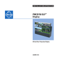
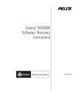
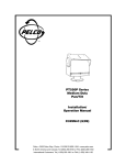
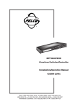
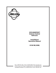
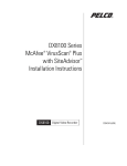
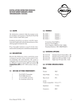
QUICK START GUIDE
PMCD750 DLP™ Display
50-Inch Rear Projection Display
C2928M-QS (7/05)
This quick start guide describes basic assembly and operation of the PMCD750 DLP™ display as a stand-alone unit and as part of a video wall.
BEFORE YOU BEGIN
DOCUMENTATION
Refer to the enclosed CD for the following documentation:
2
•
Installation/Operation manual
•
Copy of this Quick Start Guide
C2928M-QS (7/05)
Chassis Assembly
WARNING: The chassis weighs 65 lb (29.5 kg). Two people are required to handle and position the display safely.
Unpack the PMCD750 unit. The screen is not needed yet and should be left in its container at this time.
SINGLE DISPLAY
Attach the screen support to the front edge of the chassis with the supplied screen support bolts. The screen support mounts only one way.
It incorporates a stop (rest) for the screen. Refer to Figure 1.
WALL DISPLAY – FIRST ROW
Straightness of the PMCD750 display is critical because the screens have no mullion (outside screen border). If the first row in a wall
configuration is not horizontally straight, the problem will worsen as construction progresses.
To build the first row of a wall:
1. Set the first row of PMCD750 units side by side without the screens. Bolt them loosely together through the bottom connection points with
the 1/4-20 x 3.5-inch bolts, washers, and wing nuts. Refer to Figure 1.
2. Attach the screen supports to the front edge of each chassis. Refer to Figure 1.
3. Check the first row for horizontal straightness by making sure the front and top edges of adjacent units are flush. If necessary, use shims
under the units to make sure the top edges of adjacent units are flush.
4. When the first row is straight horizontally and vertically, tighten the bolts holding the units together.
SCREEN SUPPORT
BOTTOM CONNECTION POINT
Figure 1. Mounted Screen Support and Bottom Connection Point
C2928M-QS (7/05)
3
WALL DISPLAY – SECOND ROW AND UP
DANGER: Because the PMCD750 unit has a narrow front-to-back profile, the danger of tipping exists with high walls. For walls over two
units high and all tilted walls, use the four tie-back points (1/4-20 threaded holes) on the rear of the unit to secure the video wall to a
structural part of the building. If the wall is tilted forward, tie the wall all the way up. Do this as the wall is being built up; do not wait until
the wall is finished. Pelco does not provide any special brackets to secure the PMCD750 unit. The method to use is best determined on site
due to the many variables to consider, and must be capable of sustaining five times the weight of each PMCD750 unit – a total of
340 pounds (154 kilograms) per unit.
TIE BACK POINTS
Figure 2. Tie-Back Connection Points
4
C2928M-QS (7/05)
WARNING: The maximum stack height for a wall is four units.
1. Stack another row of PMCD750 units on the first row. As you stack, be careful inserting the alignment pins on the second row chassis into
the alignment holes on the lower unit. Refer to Figure 3.
SECOND
ROW
ALIGNMENT PIN DETAIL
ALIGNMENT PINS
ALIGNMENT HOLES
FIRST
ROW
Figure 3. Alignment Pin Locations (Front View)
C2928M-QS (7/05)
5
2. As each unit is placed in the second row, secure it to the front of the lower unit with two 6-32 x 3/8-inch screws. Refer to Figure 4.
FRONT SCREW CONNECTION POINTS
FRONT SCREW CONNECTION POINT DETAIL
Figure 4. Front Screw Securing Locations
6
C2928M-QS (7/05)
3. Bolt the PMCD750 units together vertically through the vertical connection points using the 1/4-20 x 3/8-inch bolts. Refer to Figure 5.
4. Bolt the PMCD750 units together through the bottom connection points the same as the first row. Refer to Figure 1.
5. Bolt the PMCD750 units together through the horizontal connection points using the 1/4-20 x 2-inch bolts, washers, and wing nuts. Refer to
Figure 5.
6. Continue in this way with the rest of the rows, checking straightness as each row is completed.
HORIZONTAL CONNECTION POINT
VERTICAL CONNECTION POINT
Figure 5. Vertical and Horizontal Connection Points
C2928M-QS (7/05)
7
Connecting Analog and Digital Sources
The PMCD750 will accept video input from devices with VGA or DVI output. Video sources with either or both of these output types can have
their images displayed on the PMCD750. Refer to Figure 6.
IN
OUT
IN
OUT
LOOPING
VGA
LOOPING
DVI
LOOPING
VIDEO SOURCE
OUTPUT
FIRST DISPLAY
SECOND DISPLAY
Figure 6. Video Input Connections
Connect the video input to the Analog 1, Analog 2, or Digital In input. Multiple inputs can be connected simultaneously. For wall systems, loop
the video out from the first display to the input connector of the second display. Continue looping until all displays are connected.
8
C2928M-QS (7/05)
Connecting RS-232 and RS-485 Control
Serial control can be used with stand-alone units, a wall, or several walls.
To connect an external controller:
1. Using a straight-through computer serial cable, connect the RS-232 input of the stand-alone unit or the first unit in the wall to the serial out
port of the external control device, such as a video controller. Refer to Figure 7.
2. Connect this first display’s RS-485 Out to the next display’s RS-485 In. Refer to Figure 7.
IN
OUT
IN
OUT
VIDEO
CONTROLLER
LOOPING
FIRST DISPLAY
SECOND DISPLAY
Figure 7. RS-232 and RS-485 Connections
C2928M-QS (7/05)
9
Installing Screens
To install a screen on a stand-alone unit, follow the instructions in steps 1a, 1b, and 1c.
1. To install the PMCD750 screens, start in the middle of the bottom row and install that screen. The screen supports should be installed on
the bottom row of PMCD750 screens.
a.
Pull the screen rails all the way out on both sides of the PMCD750 chassis. The screen rails each have a large pin that mates with the
L-shaped slot located on each side of the screen. Refer to Figure 8.
b.
With one person holding each side, hang the screen so that the pins on the screen rails go into the L-shaped slots on the sides of the
screen. Refer to Figure 9.
c.
Slide the screen closed, lifting it slightly to avoid scraping on the screen support below.
2. Install the screens to the left and right of the center screen to complete the bottom row. After adding a screen, press it toward the center.
If necessary, place shims on the top of the screen support until the screens are straight.
3. Starting in the second row and working upward and outward, finish all the rows.
SCREEN RAILS
SCREEN RAIL PIN DETAIL
Figure 8. Screen Rails
10
C2928M-QS (7/05)
Figure 9. L-Shaped Screen Slot
C2928M-QS (7/05)
11
Connecting Power
1. Bring AC power next to the electronics module. Connect the power to the receptacle located on the rear panel. The voltage can be
115 VAC (90–132 VAC) or 230 VAC (200–254 VAC). Refer to Figure 10.
POWER SWITCH
AC OUT
AC IN
Figure 10. Power Switch and Receptacles
WARNING: Do not exceed the recommended number of PMCD750 units linked in series for AC power or the current draw will be too great.
2. The AC power can be looped through to the next PMCD750 unit, resulting in fewer main outlet sockets needed for operation. The total
number of units in one power loop cannot exceed four (115 VAC) or eight (230 VAC) units.
3. Turn on the power switch for each display. When AC power is applied, there are a few seconds of apparent inactivity in which the
electronics module begins start up and initialization. Next, if the optical engine is warm, the intake and lamp fans start. Because the
service life of the lamp can be significantly shortened if turned on when hot, the lamp cannot be turned on during this time. The lamp fan
runs for approximately one minute to ensure the lamp is cool. If the temperature sensor on the optical engine determines that the lamp is
sufficiently cool at power up, this cool-down period is skipped.
NOTES:
•
The AC switch on each PMCD750 unit controls that display only. Turning off the switch on any display does not cut the AC power to the other
displays. The switch is lit when it is ON and there is AC power to the PMCD750 unit.
•
The AC input is fused with a 10 A fuse. If the fuse in any PMCD750 unit blows, all displays downstream from this one will go off.
SHUT-DOWN SEQUENCE
WARNING: Turning off the PMCD750 display by turning off the power switch does not allow the lamp to cool down properly. Turning the
display off by this method may significantly shorten the service life of the lamp.
The lamp fan runs continuously while the lamp is on. When the lamp is turned off, the intake fan shuts off 15 seconds later, while the lamp fan
continues to run for an additional 5 minutes to cool the lamp. If the display must be disconnected from power, do the following:
1. Press OFF on the remote control.
2. Wait for the lamp fan to stop running.
3. Press the AC power switch on the rear of the display to turn off the power.
4. Remove the power cord from the AC in receptacle.
12
C2928M-QS (7/05)
Using The Remote Control
Using the the remote control is the only way to access menu settings. There are no access controls on the display unit.
The remote control projects a series of IR (infrared) pulses to the PMCD750 display for control. Aim the remote control at a single display and
press MENU. The main menu should be visible if the lamp is on. Refer to Figure 11 for remote control buttons and their associated commands/
actions.
SOURCE
CURTAIN
CHANGES THE DISPLAYED INPUT
TURNS THE CURTAIN PATTERN
ON AND OFF
ON
LEVEL
TURNS THE LAMP ON
OPENS THE INPUT LEVELS MENU
OFF
FREQ/PHASE
TURNS THE LAMP OFF
OPENS THE PICTURE MENU
SAVE
SETUP
SUCCESSIVELY OPENS THE RECALL
AND SAVE MENUS WITH EACH PRESS
PERFORMS USER-SELECTED
AUTO SETUP OPTIONS
MONITOR
SIZE/POS
SUCCESSIVELY OPENS THE
MENUS FOR DISPLAY STATUS,
SERIAL PORT STATUS (RS-232),
SERIAL PORT STATUS (RS-485),
AND TEST PATTERNS WITH
EACH PRESS
SUCCESSIVELY OPENS THE
PICTURE POSITION, ZOOM
TOP & LEFT, AND ZOOM
BOTTOM & RIGHT MENUS
WITH EACH PRESS
MENU
MISC
OPENS THE MAIN MENU
SUCCESSIVELY OPENS THE
COLOR BALANCE, MISCELLANEOUS,
LAMP SETTINGS, SERIAL PORT
SETTINGS, AND AUTO SETUP MENUS
WITH EACH PRESS
WALL
OPENS THE ASPECT
RATIO AND WALL MENU
ENTER
SELECTS THE HIGHLIGHTED ITEM
AND, IN SOME CASES, CHANGES
THE VALUE
PREV
SELECTS THE PREVIOUS MENU
OPENS THE NEXT MENU, CHANGES
THE VALUE OF A SELECTED ITEM, AND
NAVIGATES RIGHT IN MENUS AND
IMAGE POSITIONING
NAVIGATES UP IN MENUS
AND IMAGE POSITIONING
OPENS THE PREVIOUS MENU, CHANGES
THE VALUE OF A SELECTED ITEM,
AND NAVIGATES LEFT IN MENUS AND
IMAGE POSITIONING
NAVIGATES DOWN IN MENUS
AND IMAGE POSITIONING
Figure 11. Remote Control Layout
C2928M-QS (7/05)
13
Alignment and Adjustment
If the image on the screen is not positioned accurately, alignment of the optical engine may be required. It is important to check this mechanical
adjustment of the optical engine before any electronic adjustments are made to the picture. Refer to the Aligning the Optical Engine section of
the Installation/Operation manual.
If the aspect ratio of the image does not match that of the display, scaling and cropping adjustments can be made to compensate. Refer to the
Scaling and Cropping section of the Installation/Operation manual.
14
C2928M-QS (7/05)
PRODUCT WARRANTY AND RETURN INFORMATION
WARRANTY
Pelco will repair or replace, without charge, any merchandise proved defective in material or
workmanship for a period of one year after the date of shipment.
Exceptions to this warranty are as noted below:
• Five years on FT/FR8000 Series fiber optic products.
• Three years on Genex ® Series products (multiplexers, server, and keyboard).
• Three years on Camclosure ® and fixed camera models, except the CC3701H-2,
CC3701H-2X, CC3751H-2, CC3651H-2X, MC3651H-2, and MC3651H-2X camera models,
which have a five-year warranty.
• Two years on standard motorized or fixed focal length lenses.
• Two years on Legacy ®, CM6700/CM6800/CM9700 Series matrix, and DF5/DF8 Series
fixed dome products.
If a warranty repair is required, the Dealer must contact Pelco at (800) 289-9100 or
(559) 292-1981 to obtain a Repair Authorization number (RA), and provide the following
information:
1. Model and serial number
2. Date of shipment, P.O. number, Sales Order number, or Pelco invoice number
3. Details of the defect or problem
If there is a dispute regarding the warranty of a product which does not fall under the
warranty conditions stated above, please include a written explanation with the product
when returned.
Method of return shipment shall be the same or equal to the method by which the item was
received by Pelco.
• Two years on Esprit ® and WW5700 Series window wiper (excluding wiper blades).
RETURNS
In order to expedite parts returned to the factory for repair or credit, please call the factory at
(800) 289-9100 or (559) 292-1981 to obtain an authorization number (CA number if returned
for credit, and RA number if returned for repair).
• Two years (except lamp and color wheel) on Digital Light Processing (DLP ™) displays. The
lamp and color wheel will be covered for a period of 90 days. The air filter is not covered
under warranty.
All merchandise returned for credit may be subject to a 20% restocking and refurbishing
charge.
• Eighteen months on DX Series digital video recorders, NVR300 Series network video
recorders, and Endura ™ Series distributed network-based video products.
Goods returned for repair or credit should be clearly identified with the assigned CA or RA
number and freight should be prepaid. Ship to the appropriate address below.
• Two years on Spectra ®, Esprit®, ExSite™, and PS20 scanners, including when used in
continuous motion applications.
• One year (except video heads) on video cassette recorders (VCRs). Video heads will be
covered for a period of six months.
• Six months on all pan and tilts, scanners or preset lenses used in continuous motion
applications (that is, preset scan, tour and auto scan modes).
Pelco will warrant all replacement parts and repairs for 90 days from the date of Pelco
shipment. All goods requiring warranty repair shall be sent freight prepaid to Pelco, Clovis,
California. Repairs made necessary by reason of misuse, alteration, normal wear, or accident
are not covered under this warranty.
Pelco assumes no risk and shall be subject to no liability for damages or loss resulting from
the specific use or application made of the Products. Pelco’s liability for any claim, whether
based on breach of contract, negligence, infringement of any rights of any party or product
liability, relating to the Products shall not exceed the price paid by the Dealer to Pelco for
such Products. In no event will Pelco be liable for any special, incidental or consequential
damages (including loss of use, loss of profit and claims of third parties) however caused,
whether by the negligence of Pelco or otherwise.
The above warranty provides the Dealer with specific legal rights. The Dealer may also have
additional rights, which are subject to variation from state to state.
If you are located within the continental U.S., Alaska, Hawaii or Puerto Rico, send goods to:
Service Department
Pelco
3500 Pelco Way
Clovis, CA 93612-5699
If you are located outside the continental U.S., Alaska, Hawaii or Puerto Rico and are
instructed to return goods to the USA, you may do one of the following:
If the goods are to be sent by a COURIER SERVICE, send the goods to:
Pelco
3500 Pelco Way
Clovis, CA 93612-5699 USA
If the goods are to be sent by a FREIGHT FORWARDER, send the goods to:
Pelco c/o Expeditors
473 Eccles Avenue
South San Francisco, CA 94080 USA
Phone: 650-737-1700
Fax: 650-737-0933
This equipment contains electrical or electronic components that must be recycled properly to comply with Directive 2002/96/EC of the European Union
regarding the disposal of waste electrical and electronic equipment (WEEE). Contact your local dealer for procedures for recycling this equipment.
REVISION HISTORY
Manual #
C2928M-QS
Date
7/05
Comments
Original version.
Pelco, the Pelco logo, Camclosure, Esprit, Genex, Legacy, and Spectra are registered trademarks of Pelco.
Endura and ExSite are trademarks of Pelco.
DLP is a trademark of Texas Instruments, Inc.
©Copyright 2005, Pelco. All rights reserved.
Worldwide Headquarters
3500 Pelco Way
Clovis, California 93612 USA
USA & Canada
Tel: 800/289-9100
Fax: 800/289-9150
International
Tel: 1-559/292-1981
Fax: 1-559/348-1120
www.pelco.com
ISO9001
United States
|
Canada
|
United Kingdom
|
The Netherlands
| Singapore | Spain | Scandinavia | France | Middle East