1
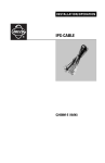
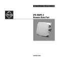
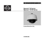
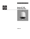
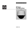
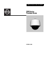
I N S T A L L A T I O N
DF8 Series
Pendant Dome
C2433M-D (9/06)
Contents
Important Safety Instructions . . . . . . . . . . . . . . . . . . . . . . . . . . . . . . . . . . . . . . . . . . . . . . . . . . . . . . . . . . . . . . . . . . . . . . . . . . . . . . . . . . . . . . . . . . . . 3
Description . . . . . . . . . . . . . . . . . . . . . . . . . . . . . . . . . . . . . . . . . . . . . . . . . . . . . . . . . . . . . . . . . . . . . . . . . . . . . . . . . . . . . . . . . . . . . . . . . . . . . . . . . . 4
Models . . . . . . . . . . . . . . . . . . . . . . . . . . . . . . . . . . . . . . . . . . . . . . . . . . . . . . . . . . . . . . . . . . . . . . . . . . . . . . . . . . . . . . . . . . . . . . . . . . . . . . . . . 4
Installation . . . . . . . . . . . . . . . . . . . . . . . . . . . . . . . . . . . . . . . . . . . . . . . . . . . . . . . . . . . . . . . . . . . . . . . . . . . . . . . . . . . . . . . . . . . . . . . . . . . . . . . . . . 5
Parts List . . . . . . . . . . . . . . . . . . . . . . . . . . . . . . . . . . . . . . . . . . . . . . . . . . . . . . . . . . . . . . . . . . . . . . . . . . . . . . . . . . . . . . . . . . . . . . . . . . . . . . . 5
Back Box . . . . . . . . . . . . . . . . . . . . . . . . . . . . . . . . . . . . . . . . . . . . . . . . . . . . . . . . . . . . . . . . . . . . . . . . . . . . . . . . . . . . . . . . . . . . . . . . . . . 5
Lower Dome . . . . . . . . . . . . . . . . . . . . . . . . . . . . . . . . . . . . . . . . . . . . . . . . . . . . . . . . . . . . . . . . . . . . . . . . . . . . . . . . . . . . . . . . . . . . . . . . 5
Back Box . . . . . . . . . . . . . . . . . . . . . . . . . . . . . . . . . . . . . . . . . . . . . . . . . . . . . . . . . . . . . . . . . . . . . . . . . . . . . . . . . . . . . . . . . . . . . . . . . . . . . . . . 5
Pendant Mount . . . . . . . . . . . . . . . . . . . . . . . . . . . . . . . . . . . . . . . . . . . . . . . . . . . . . . . . . . . . . . . . . . . . . . . . . . . . . . . . . . . . . . . . . . . . . . 5
Surface Mount . . . . . . . . . . . . . . . . . . . . . . . . . . . . . . . . . . . . . . . . . . . . . . . . . . . . . . . . . . . . . . . . . . . . . . . . . . . . . . . . . . . . . . . . . . . . . . 6
Camera and Lens . . . . . . . . . . . . . . . . . . . . . . . . . . . . . . . . . . . . . . . . . . . . . . . . . . . . . . . . . . . . . . . . . . . . . . . . . . . . . . . . . . . . . . . . . . . . . . . . . 8
Lower Dome . . . . . . . . . . . . . . . . . . . . . . . . . . . . . . . . . . . . . . . . . . . . . . . . . . . . . . . . . . . . . . . . . . . . . . . . . . . . . . . . . . . . . . . . . . . . . . . . . . . . . 8
Maintenance . . . . . . . . . . . . . . . . . . . . . . . . . . . . . . . . . . . . . . . . . . . . . . . . . . . . . . . . . . . . . . . . . . . . . . . . . . . . . . . . . . . . . . . . . . . . . . . . . . . . . . . . 10
Service Manual . . . . . . . . . . . . . . . . . . . . . . . . . . . . . . . . . . . . . . . . . . . . . . . . . . . . . . . . . . . . . . . . . . . . . . . . . . . . . . . . . . . . . . . . . . . . . . . . . 10
Specifications . . . . . . . . . . . . . . . . . . . . . . . . . . . . . . . . . . . . . . . . . . . . . . . . . . . . . . . . . . . . . . . . . . . . . . . . . . . . . . . . . . . . . . . . . . . . . . . . . . . . . . . 11
2
C2433M-D (9/06)
Important Safety Instructions
1. Read these instructions.
2. Keep these instructions.
3. Heed all warnings.
4. Follow all instructions.
5. Do not block any ventilation openings. Install in accordance with the manufacturer’s instructions.
6. Do not install near any heat sources, such as radiators, heat registers, stoves, or other apparatus (including amplifiers) that produce heat.
7. Only use attachments/accessories specified by the manufacturer.
8. Use only with the cart, stand, tripod, bracket, or table specified by the manufacturer or sold with the apparatus. When a cart is used, use
caution when moving the cart/apparatus combination to avoid injury from tip-over.
9. Refer all servicing to qualified service personnel. Servicing is required when the apparatus has been damaged in any way, such as powersupply cord or plug is damaged, liquid has been spilled or objects have fallen into the apparatus, the apparatus has been exposed to rain or
moisture, the apparatus does not operate normally, or the apparatus has been dropped.
10. To reduce the risk of shock, do not perform any servicing other than that contained in the operating instructions unless you are qualified to
do so.
11. Only use replacement parts Pelco recommends.
12. After replacing/repairing this unit’s electrical components, conduct a resistance measurement between line and exposed parts to verify the
exposed parts have not been connected to line circuitry.
13. The installation method and materials should be capable of supporting four times the weight of the enclosure, pan/tilt, camera, and lens
combination.
The product and/or manual may bear the following marks:
This symbol indicates that dangerous voltage constituting a risk of
electric shock is present within this unit.
This symbol indicates that there are important operating and
maintenance instructions in the literature accompanying this unit.
C2433M-D (9/06)
CAUTION:
RISK OF ELECTRIC SHOCK.
DO NOT OPEN.
3
Description
DF8 Series pendant domes are discreet surveillance domes that are designed for indoor or outdoor use.
Indoor pendant models come in light gray or black finish. Outdoor pendant models are light gray only and include a heater that allows operation
down to -60°F (-51°C).
MODELS
4
DF8-PB-0
Indoor, black, fixed mount pendant dome, black opaque lower dome with smoked viewing window (0.7 F-stop of light loss)
DF8-PB-1
Same as DF8-PB-0, except clear viewing window (virtually no light loss)
DF8-PB-2
Same as DF8-PB-0, except chrome lower dome (2 F-stops of light loss)
DF8-PB-3
Same as DF8-PB-0, except gold lower dome (2 F-stops of light loss)
DF8-PG-0
Indoor, gray, fixed mount pendant dome, black opaque lower dome with smoked viewing window (0.7 F-stop of light loss)
DF8-PG-1
Same as DF8-PG-0, except clear viewing window (virtually no light loss)
DF8-PG-2
Same as DF8-PG-0, except chrome lower dome (2 F-stops of light loss)
DF8-PG-3
Same as DF8-PG-0, except gold lower dome (2 F-stops of light loss)
DF8-PG-E0
Outdoor, gray, fixed mount pendant dome, heater and blower, black opaque lower dome with smoked viewing window
(0.7 F-stop of light loss)
DF8-PG-E1
Same as DF8-PG-E0, except clear viewing window (virtually no light loss)
C2433M-D (9/06)
Installation
PARTS LIST
The DF8 shipping carton contains two boxes. Inspect each box to make sure all parts are present.
BACK BOX
1
Back box
1
1
1
1
1
Parts bag
Flat washer
Split lock washer
Screw
Thread compound
LOWER DOME
1
Acrylic lower dome with trim ring
1
1
1
1
Parts bag
O-ring
O-ring lubricant
Loctite® threadlocker
BACK BOX
PENDANT MOUNT
NOTE: If installing outdoors, make sure the back box is properly sealed to keep moisture out.
1. Install the mount for the pendant dome. Refer to the instructions supplied with the mount.
2. Bring the wiring for the dome through the mount. Refer to Table A and Table B for wiring distances.
3. Loosen the nut that holds the tilt table assembly to the base of the back box. Move the tilt table assembly as necessary and bring the wiring
into the dome. Re-center the tilt table assembly and hand-tighten the nut.
4. Apply thread compound (supplied) to the threads on the back box and screw the back box into the mount.
Figure 1. Installing Pendant Mount and Back Box
C2433M-D (9/06)
5
SURFACE MOUNT
NOTE: If installing outdoors, apply a sealant between the back box and the mounting surface.
1. Unscrew the three Phillips screws located inside the back box. Remove the top portion of the back box.
Figure 2. Removing the Top Mount from the Back Box
2. Determine the mounting location. Use the base of the back box as a template. Mark the fastener and center hole positions onto the
mounting surface.
3. Prepare the holes for the wiring and fasteners.
4. Prepare the wiring for camera and lens power; refer to Table A and Table B for wiring distances.
5. Position the back box over the mounting holes and pull wiring into the back box. Secure the back box to the mounting surface using the
appropriate hardware for your installation.
Figure 3. Installing the Surface Mount Back Box
6
C2433M-D (9/06)
Table A. Video Coaxial Cable Requirements
Cable Type*
Maximum Distance
RG59/U
750 ft (229 m)
RG6/U
1,000 ft (305 m)
RG11/U
1,500 ft (457 m)
*Cable requirements:
75 ohms impedance
All-copper center conductor
All-copper braided shield with 95% braid coverage
Table B. 24 VAC Wiring Distances
The following are the recommended maximum distances for 24 VAC applications and are calculated with a 10-percent voltage drop.
(Ten percent is generally the maximum allowable voltage drop for AC-powered devices.)
20
18
16
14
12
10
10
283 (86)
451 (137)
716 (218)
1142 (348)
1811 (551)
2880 (877)
20
141 (42)
225 (68)
358 (109)
571 (174)
905 (275)
1440 (438)
30
94 (28)
150 (45)
238 (72)
380 (115)
603 (183)
960 (292)
40
70 (21)
112 (34)
179 (54)
285 (86)
452 (137)
720 (219)
50
56 (17)
90 (27)
143 (43)
228 (69)
362 (110)
576 (175)
Maximum distance from
transformer to load
Total VA consumed
Wire Gauge
EXAMPLE: An enclosure that requires 30 VA and is installed 94 feet (28 m) from the transformer would require a minimum wire gauge of
20 AWG.
NOTE:
•
Models with heaters require 24 VAC for the heater. The heater uses 53 VA. If the camera uses 24 VAC, add the camera power to that of the
heater and refer to Table B to determine the size of wire to use.
•
Distances are calculated in feet; values in parentheses are meters.
C2433M-D (9/06)
7
CAMERA AND LENS
To install the camera and lens:
1. Outdoor models only: Connect 24 VAC power input wires to the AC IN connectors on the terminal block on the side of the back box.
2. Extend the lens to the maximum length before installing the camera in the back box.
3. Attach the camera to the tilt table with the 1/4-20 screw, flat washer, and split lock washer (supplied).
4. To ensure that the lens will not hit the lower dome:
• Place the lower dome over the back box with the camera and lens installed (do not attach dome).
• If the lens touches the lower dome, adjust the tilt table assembly.
5. Refer to the manual supplied with the camera and lens for the following information:
•
•
How to connect power and video wiring
How to make camera and lens adjustments
Outdoor models only: If the camera will use 24 VAC, red and black power leads are provided for the camera. The leads are attached to
the terminal block on the side of the back box.
6. Loosen the two nuts on the tilt table assembly and position the camera. Tighten the nuts.
LOWER DOME
NOTE: If you are installing the dome outdoors, plug the two-pin heater connection in the lower dome into the mating connector in the back box.
1. If the lower dome has a smoked or clear viewing slot, loosen the six retaining screws inside the rim. Refer to Figure 5 and hold the lower
dome up against the back box with the mounting screws lined up with the mounting holes in the back box. Rotate the acrylic dome to line
up the viewing slot with the camera. Retighten the six retaining screws.
2. Lightly apply O-ring lubricant to the O-ring. Install the O-ring in the groove of the trim ring.
Figure 4. Installing the O-Ring
8
C2433M-D (9/06)
3. Attach the trim ring leash to the T-shaped sheet metal tab on the retaining ring of the lower dome. Tuck the end of the trim ring leash
behind the raised sheet metal stop, and make sure the leash will hold the lower dome.
LEASH
ATTACH
LEASH TO
SHEET
METAL TAB
MOUNTING
SCREW HOLES
FRONT & BACK
Figure 5. Attaching the Trim Ring Leash
4. Remove the two mounting screws. Apply a drop of Loctite threadlocker #222 (supplied) to each screw. Line up the mounting screw holes,
push the lower dome inside the back box, and reinstall the mounting screws.
Figure 6. Installing the Lower Dome
C2433M-D (9/06)
9
Maintenance
Clean the acrylic dome as needed. Be careful not to scratch the surfaces of the dome.
Exterior surface: Clean the dome’s exterior surface with a nonabrasive cleaning cloth and agent that is safe for acrylic plastic. Either liquid or
spray cleaner/wax suitable for fine furniture is acceptable.
Interior surface (except chrome or gold): Clean the same as the exterior surface.
Interior surface (chrome or gold): The inside surface of a chrome or gold dome is easily scratched. Use the following precautions to maintain
the dome’s surface.
a.
Always handle the dome from the outside of its circular flange.
b.
Never touch the coated inside surface. The acid in your fingerprints will eventually etch the coating if the fingerprints are not carefully
removed according to the recommended cleaning procedure in item e.
c.
If dust or other contaminants accumulate on the dome’s interior, remove the debris with compressed air. Compressed air cans are
available from photographic equipment or electronic supply dealers.
d.
If heavy residue accumulates and cannot be removed with air pressure, rinse with water and immediately dry with air pressure so that
water spots will not remain. Avoid wiping the coated surface with direct hand pressure – it will easily abrade unless extreme care is
taken. Once scratched, the dome cannot be repaired.
e.
If internal wiping is necessary, avoid hand rubbing. Instead, make a wick as follows:
Use a very soft paper towel. Roll a section into a tightly wound tube. Tear the tube in half, and wet the fuzzy end of the wick with a
solution of isopropyl alcohol diluted with water. Hold the dome with its opening facing downward and wipe the interior of the dome
with the wet end of the wick. Use a circular motion, starting from the outside and spiraling into the center. Use a new wick for each
two passes over the dome.
SERVICE MANUAL
If you need to service your unit, obtain a service manual in one of the following ways:
10
•
Go to Pelco’s web site at www.pelco.com and find service manual C2433SM.
•
Contact Pelco’s Literature Department and request service manual C2433SM.
C2433M-D (9/06)
Specifications
ELECTRICAL
Input Voltage
14-30 VAC (outdoor models only)
Input Power
53 VA at 24 VAC (for heater and blower)
GENERAL
Construction
Back Box
Mounting Bracket
Lower Dome
Trim Ring
Aluminum
Steel
Acrylic
Aluminum
Dimensions
See dimension drawing
Environment
Indoor and outdoor
Operating Temperature
Indoor
Outdoor*
32° to 120°F (0° to 49°C)
-60° to 122°F (-51° to 50°C)
continuous operation -50° to 122°F (-46° to 50°C)
continuous operation; prevents icing -40° to 122°F (-40° to 50°C)
continuous operation; de-ices within 3 hours after power-up
Weight (without camera)
6.00 lb (2.72 kg); add 2.50 (1.13 kg) for heater and sun shield
Ratings
Meets NEMA Type 4X and IP66 standards
Assumes no windchill factor.
CAMERA
Maximum Camera and
Lens Size
The following dimensions are specified according to fixed camera mount position and include allowance
for the BNC connector. Actual length may vary if width and height of camera and lens are different.
Horizontal:
7.25" L x 2.75" W x 2.60" H
(19.05 x 6.99 x 6.60 cm)
15 Degree Angle: 7.75" L x 3.00" W x 3.00" H
(20.32 x 7.62 x 7.62 cm)
30 Degree Angle: 8.75" L x 3.00" W x 3.00" H
(22.86 x 7.62 x7.62 cm)
(Design and product specifications subject to change without notice.)
13.18
(33.47)
8.30 (21.08)
11.05 (28.06) B
12.13 (30.81) A
A - OUTDOOR MODELS WITH SUN SHIELD
B - INDOOR MODELS WITHOUT SUN SHIELD
NOTE: VALUES IN PARENTHESES ARE CENTIMETERS; ALL OTHERS ARE INCHES.
C2433M-D (9/06)
11
PRODUCT WARRANTY AND RETURN INFORMATION
WARRANTY
Pelco will repair or replace, without charge, any merchandise proved defective in material or
workmanship for a period of one year after the date of shipment.
Exceptions to this warranty are as noted below:
• Five years on FR/FT/FS Series fiber optic products and TW3000 Series unshielded twisted
pair transmission products.
• Three years on Genex® Series products (multiplexers, server, and keyboard).
• Three years on Camclosure® and fixed camera models, except the CC3701H-2,
CC3701H-2X, CC3751H-2, CC3651H-2X, MC3651H-2, and MC3651H-2X camera models,
which have a five-year warranty.
• Three years on PMCL200/300/400 Series LCD monitors.
• Two years on standard motorized or fixed focal length lenses.
• Two years on Legacy®, CM6700/CM6800/CM9700 Series matrix, and DF5/DF8 Series fixed
dome products.
®
®
™
• Two years on Spectra , Esprit , ExSite , and PS20 scanners, including when used in
continuous motion applications.
• Two years on Esprit® and WW5700 Series window wiper (excluding wiper blades).
• Two years (except lamp and color wheel) on Digital Light Processing (DLP®) displays.
The lamp and color wheel will be covered for a period of 90 days. The air filter is not
covered under warranty.
• Eighteen months on DX Series digital video recorders, NVR300 Series network video
recorders, and Endura™ Series distributed network-based video products.
• One year (except video heads) on video cassette recorders (VCRs). Video heads will be
covered for a period of six months.
• Six months on all pan and tilts, scanners or preset lenses used in continuous motion
applications (that is, preset scan, tour and auto scan modes).
Pelco will warrant all replacement parts and repairs for 90 days from the date of Pelco
shipment. All goods requiring warranty repair shall be sent freight prepaid to Pelco, Clovis,
California. Repairs made necessary by reason of misuse, alteration, normal wear, or accident
are not covered under this warranty.
Pelco assumes no risk and shall be subject to no liability for damages or loss resulting from
the specific use or application made of the Products. Pelco’s liability for any claim, whether
based on breach of contract, negligence, infringement of any rights of any party or product liability, relating to the Products shall not exceed the price paid by the Dealer to Pelco for such
Products. In no event will Pelco be liable for any special, incidental or consequential damages
(including loss of use, loss of profit and claims of third parties) however caused, whether by
the negligence of Pelco or otherwise.
The above warranty provides the Dealer with specific legal rights. The Dealer may also have
additional rights, which are subject to variation from state to state.
If a warranty repair is required, the Dealer must contact Pelco at (800)þ289-9100 or
(559) 292-1981 to obtain a Repair Authorization number (RA), and provide the following
information:
1. Model and serial number
2. Date of shipment, P.O. number, Sales Order number, or Pelco invoice number
3. Details of the defect or problem
If there is a dispute regarding the warranty of a product which does not fall under the
warranty conditions stated above, please include a written explanation with the product when
returned.
Method of return shipment shall be the same or equal to the method by which the item was
received by Pelco.
RETURNS
In order to expedite parts returned to the factory for repair or credit, please call the factory at
(800) 289-9100 or (559) 292-1981 to obtain an authorization number (CA number if returned for
credit, and RA number if returned for repair).
All merchandise returned for credit may be subject to a 20% restocking and refurbishing
charge.
Goods returned for repair or credit should be clearly identified with the assigned CA or RA
number and freight should be prepaid. Ship to the appropriate address below.
If you are located within the continental U.S., Alaska, Hawaii or Puerto Rico, send goods to:
Service Department
Pelco
3500 Pelco Way
Clovis, CA 93612-5699
If you are located outside the continental U.S., Alaska, Hawaii or Puerto Rico and are
instructed to return goods to the USA, you may do one of the following:
If the goods are to be sent by a COURIER SERVICE, send the goods to:
Pelco
3500 Pelco Way
Clovis, CA 93612-5699 USA
If the goods are to be sent by a FREIGHT FORWARDER, send the goods to:
Pelco c/o Expeditors
473 Eccles Avenue
South San Francisco, CA 94080 USA
Phone: 650-737-1700
Fax: 650-737-0933
The materials used in the manufacture of this document and its components are compliant to the requirements of Directive 2002/95/EC.
This equipment contains electrical or electronic components that must be recycled properly to comply with Directive 2002/96/EC of the European Union
regarding the disposal of waste electrical and electronic equipment (WEEE). Contact your local dealer for procedures for recycling this equipment.
REVISION HISTORY
Manual #
C2433M
C2433M-A
Date
7/01
9/01
C2433M-B
C2433M-C
C2433M-D
8/02
10/03
9/06
Comments
Original version.
Revised manual for redesigned product. Also revised model descriptions, voltage specifications, and dimension drawing. Added additional instructions for heater
installation. Removed ratings.
Added certifications. Revised Important Safeguards and Warnings.
Added NEMA Type 4X and IP66 certifications.
Revised per ECO 05-11636, which incorporated Spectra III style back box and heater/blower assembly. Revised F-stop values and maximum camera and lens size
per ECO 06-14186.
Pelco, the Pelco logo, Camclosure, Esprit, Genex, Legacy, and Spectra are registered trademarks of Pelco.
Endura and ExSite are trademarks of Pelco.
DLP is a registered trademark of Texas Instruments, Inc.
Loctite is a registered trademark of the Loctite Corporation.
Worldwide Headquarters • 3500 Pelco Way • Clovis, California 93612 USA • www.pelco.com
USA & Canada • Tel: 800/289-9100 • Fax: 800/289-9150
International • Tel: 1-559/292-1981 • Fax: 1-559/348-1120
©Copyright 2006, Pelco. All rights reserved.