1
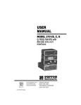
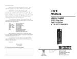
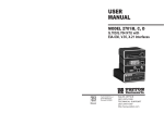
USER
MANUAL
MODEL 1094
KiloModem-768 High
Speed Baseband Modem
TM
Part# 07M1094-C
Doc# 032031UC
R evised 04/13/99
CERTIFIED
An ISO-9001
Certified Company
SALES OFFICE
(301) 975-1000
TECHNICAL SUPPORT
(301) 975-1007
http://www.patton.com
1.0 WARRANTY INFORMATION
1.3 SERVICE
Patton Electronics warrants all Model 1094 components to be
free from defects, and will—at our option—repair or replace the product
should it fail within one year from the first date of shipment.
This warranty is limited to defects in workmanship or materials,
and does not cover customer damage, abuse or unauthorized modification. If this product fails or does not perform as warranted, your sole
recourse shall be repair or replacement as described above. Under no
condition shall Patton Electronics be liable for any damages incurred
by the use of this product. These damages include, but are not limited
to, the following: lost profits, lost savings and incidental or consequential damages arising from the use of or inability to use this product.
Patton Electronics specifically disclaims all other warranties,
expressed or implied, and the installation or use of this product shall be
deemed an acceptance of these terms by the user.
1.1 RADIO AND TV INTERFERENCE
The Model 1094 generates and uses radio frequency energy, and
if not installed and used properly—that is, in strict accordance with the
manufacturer's instructions—may cause interference to radio and television reception. The Model 1094 has been tested and found to comply with the limits for a Class A computing device in accordance with
the specifications in Subpart J of Part 15 of FCC rules, which are
designed to provide reasonable protection from such interference in a
commercial installation. However, there is no guarantee that interference will not occur in a particular installation. If the Model 1094 does
cause interference to radio or television reception, which can be determined by removing power from the unit, the user is encouraged to try
to correct the interference by one or more of the following measures:
moving the computing equipment away from the receiver, re-orienting
the receiving antenna and/or plugging the receiving equipment into a
different AC outlet (such that the computing equipment and receiver
are on different branches).
All warranty and non-warranty repairs must be returned freight prepaid and insured to Patton Electronics. All returns must have a Return
Materials Authorization number on the outside of the shipping container. This number may be obtained from Patton Electronics Technical
Service at:
TEL: (301) 975-1007
Email: [email protected].
www: http://www.patton.com
NOTE:
Packages received without an RMA number will not be
accepted.
Patton Electronics’ technical staff is also available to answer any
questions that might arise concerning the installation or use of your
Model 1094. Technical Support hours: 8AM to 5PM EST, Monday
through Friday.
1.2 CE NOTICE
The CE symbol on your Patton Electronics equipment indicates
that it is in compliance with the Electromagnetic Compatibility (EMC)
directive and the Low Voltage Directive (LVD) of the Union European
(EU). A Certificate of Compliance is available by contacting Technical
Support.
1
2
2.0 GENERAL INFORMATION
3.0 CONFIGURATION
Thank you for your purchase of this Patton Electronics product.
This product has been thoroughly inspected and tested and is warranted for One Year parts and labor. If any questions or problems arise
during installation or use of this product, please do not hesitate to contact Patton Electronics Technical Support at (301) 975-1007.
The Model 1094 is equipped with one set of eight DIP switches,
and one set of four DIP switches (all externally accessible). These DIP
switches allow configuration of clock source, carrier control, loopback
tests and data rate. This section describes switch locations and
explains all possible configurations.
2.1 FEATURES
3.1 EXTERNAL DIP SWITCH SETTINGS
• Synchronous data rates of 384 and 768 kbps
• Frequency Shift Key (FSK) modulation
• Full or half duplex operation over two twisted pair (4-wire)
• Point-to-point distances up to 4.9 miles (19 AWG @ 384 kbps)
The Model 1094’s DIP switches are located on the underside of
the unit (see Figure 1, below). Figure 2 shows the orientation of the
switch set. All possible settings for the Model 1094’s DIP switches are
presented in the summary table and descriptions on the following
pages.
• V.54 compliant local and remote loopback tests (DTE or
front panel activated)
REAR
• V.52 compliant Bit Error Rate (BER) test pattern generator
• Replaceable DTE-DCE QuickConnect™ interface modules
S1
S2
• Internal, external or receive recovered clocking options
• Automatic equalization
1 2 3 4 5 6 7 8
1 2 3 4
ON
ON
• Made in the U.S.A.
2.2 DESCRIPTION
The Patton Model 1094 Synchronous Short Range Modem
is designed for point-to-point, high speed communication over 4-wires
(two twisted pair). Supporting switch-selectable data rates of 384 and
768 kbps, the Model 1094 is perfect for connecting two bridge/routers,
or for similar campus applications at distances up to 4.9 miles (7.9 km).
The Model 1094 incorporates built-in V.54 loopback tests, a V.52 BERT
pattern generator and seven front panel LED indicators. Data integrity
is enhanced by automatic equalization and gain control. The Model
1094 also incorporates transformer isolation and surge protection to
guard data and connected equipment against the hazards of ground
loops and transient surges. Clocking options include internal, external
and receive recover clock.
The Model 1094 features replaceable DCE-DTE QuickConnect™
interface modules. Several different modules are available (call Patton
Sales for details). Line connection is made by RJ-45 jack. Internal AC
power supply options include 120 or 230VAC (switchable), 85-256VAC
(universal) or 48VDC.
FRONT
Figure 1. Underside of Model 1094 Showing External DIP Switch Locations
S2
S1
ON
ON
ON
1 2 3 4 5 6 7 8
1 2 3 4
Figure 2. Close Up of Configuration Switches
3
4
OFF
Switch S1-3: RTS/CTS Delay
S1 SUMMARY TABLE
Position
Function
Factory Default
S1-1
Clock Source*
On
S1-2
Clock Source*
On
S1-3
RTS/CTS Delay
On
Short Delay
S1-4
LDL
Off
Disabled
S1-5
Carrier Control
Off
Constant
S1-6
DTE Control of RDL
Off
Disabled
S1-7
DTE Control of LAL
Off
Disabled
S1-8
V.54 Enable/Disable
Off
Enabled
}
Internal
*See Note in SWITCH SET S1 (Below) for X.21 Clock Sources
3.1.1 Switch Set S1
The configuration switches on S1 set clock source, RTS/CTS
delay, carrier control, loopback tests. The default settings are summarized in the table above.
Switches S1-1 and S1-2: Clock Source
Switches S1-1 and S1-2 are set in combination to determine the
source of timing for the Model 1094.
Switch S1-3 is used in combination to determine the amount of
delay between the time RTS is activated and the 1094 activates the
CTS.
S1-3
On
Off
Function
Short delay (1-4 ms)
Long delay (8-20 ms)
Switch S1-4: LDL Control
Switch S1-4 determines whether the frontt panel switch can activate a Local Digital Loopback (LDL) diagnostic test.
S1-4
On
Off
Function
LDL Control Enabled
LDL Control Disabled
Switch S1-5: Carrier Control
The setting for switch S1-5 determines whether the carrier is “constantly on” or “controlled by RTS”. This setting allows for operation in
switched carrier or hardware handshaking applications.
S1-5
On
Off
Setting
Controlled by RTS
Constantly ON
Switch S1-6: DTE Control of RDL
S1-1
On
On
Off
Off
S1-2
On
Off
On
Off
Setting
Internal
Receive recover
External transmit clock
Not a valid setting
NOTE: When an X.21 QuickConnect™ module is installed in
one or both base units, one base unit must be configured for
receive recover clock source. The particular application will
dictate which unit must be configured for receive recover clock
source.
The setting for switch S1-6 determines whether DTE control of
remote-digital loopback test is enabled or disabled. If DTE control is
disabled, the RDL test can only be initiated by the front panel switch.
S1-6
On
Off
Switch S1-7: DTE Control of LAL
The setting for switch S1-7 determines whether DTE control of
local analog loopback test is enabled or disabled. If DTE control is disabled, the LAL test can only be initiated by the front panel switch.
S1-7
On
Off
5
Setting
DTE control enabled
DTE control disabled
Setting
DTE control enabled
DTE control disabled
6
4.0 INSTALLATION
Switch S1-8: V.54 Enable / Disable
The setting for switch S1-8 determines whether the Model 1094
will respond when it receives the V.54 sequence. If you suspect the
Model 1094 may be getting tricked into the loopback test by false
detection of user data, you can try setting this to “Disable.”
S1-8
On
Off
4.1 CONNECTION TO THE TWISTED PAIR INTERFACE
Setting
Disabled
Enabled
The Model 1094 supports communication between two terminal
devices at distances to 4.9 miles (7.9 km) and data rates to 768 kbps.
There are two essential requirements for installing the Model 1094:
3.1.2 Switch Set S2
The settings for DIP switches S2-1 through S2-4 determine the
synchronous data rate of the Model 1094. All possible settings (including the default) are shown below:
S2-1
Off
On
S2-2
On
Off
Once the Model 1094 is properly configured, it is ready to connect
to the twisted pair interface, to the serial port, and to the power source.
This section tells you how to make these connections.
S2-3
On
Off
S2-4
On
Off
Setting
384 kbps
768 kbps (default)
1.
These units work in pairs. Therefore, you must have one
Model 1094 (or a compatible model) at each end of a two
twisted pair interface.
2.
To function properly, the Model 1094 needs two twisted pairs
of metallic wire. These twisted pairs must be
unconditioned, dry, metallic wire, between 19 and 26 AWG
(.4 mm and .9 mm, inversely) (the higher AWG gauges may
limit distance somewhat). Standard dial-equalization
equipment, or standard, flat modular telephone type cable, are
not acceptable.
4.1.1 TWISTED PAIR CONNECTION USING RJ-45
The Model 1094 uses a modular RJ-45 jack for twisted pair line
connection. The signal/pin relationships are shown below:
RJ-45
SIGNAL
1 ..........................XMT+
2 ..........................XMT3 ..........................N/C
4 ..........................GND*
5 ..........................GND*
6 ..........................N/C
7 ..........................RCV+
8 ..........................RCV-
1
2
3
4
5
6
7
8
*Connection to ground is optional
7
8
When connecting two Model 1094’s, it is necessary to use a
crossover cable. The diagram below shows how a crossover cable
should be constructed.
RJ-45 Cable (4-Wire)
SIGNAL
PIN#
PIN#
XMT+
XMTGND*
GND*
RCV+
RCV-
1-----------------------8
2-----------------------7
4-----------------------5
5-----------------------4
7-----------------------2
8-----------------------1
4.2.1 CHANGING QUICKCONNECT™ MODULES
When you purchase a particular version of the Model 1094, it
should be shipped to you with the appropriate QuickConnect™
Module already installed. If you need to install a different
QuickConnect™ Module, follow these steps.
SIGNAL
Removing the Existing QuickConnect™ Module
RCVRCV+
GND*
GND*
XMTXMT+
*Connection to ground is optional
1. Turn the power switch off. Leave the power cord plugged into a
grounded outlet to keep the unit grounded.
2. Loosen the two thumbscrews on the module by turning them
counterclockwise.
3. Grasp the two thumbscrews and gently pull the module from
the unit. Apply equal force to the thumbscrews to keep the
module straight during the removal process.
4.2 CONNECTION TO THE SERIAL PORT
Installing the New QuickConnect™ Module
The serial port interface on the Model 1094 uses interchangeable
Quick Connect Modules. Each Quick Connect Module has a 50-pin
card edge connector on one side and a serial port interface on the
other. Figure 3 (below) shows how a Quick Connect™ Module plugs
into the back of the Model 1094.
1. Make sure the power switch is off. Leave the power cord
plugged into a grounded outlet to keep the unit grounded.
2. Hold the module with the faceplate toward you and align the
module with the guide slots in the rear panel of the Model
1094.
3. While keeping the module’s faceplate parallel with the Model
1094 rear panel, slide the module straight in–so that the card
edge contacts line up with the socket inside the chassis.
e
Lin
ort
eP
ac
erf
Int
N
1O
FF
0O
Figure 3. Installation of Model 1094 Plug-in Serial Interface Module
NOTE: The card edge connector should meet the socket when
it is almost all the way into the chassis. If you encounter a lot of
resistance, remove the module and repeat Steps 2 and 3.
4. With the card edge contacts aligned with the socket, firmly seat
the module by using your thumbs to apply pressure directly to
the right and left edges of the module faceplate. Applying moderate and even pressure should be sufficient to seat the module. You should hear it snap into place.
5. To secure the module in place, push the thumbscrews into the
chassis and turn the screws clockwise to tighten.
9
10
4.2.2 CONNECTION TO A “DTE” DEVICE
The serial port on most QuickConnect™ interface modules (all
except the X.21 module) is hard-wired as a DCE. Therefore these
modules “want” to plug into a DTE such as a terminal, PC or host.
When making the connection to your DTE device, use a straight
through cable of the shortest possible length—we recommend 6 feet
or less. When purchasing or constructing an interface cable, please
refer to the pin diagrams in Appendix D as a guide.
4.2.3 CONNECTION TO A “DCE” DEVICE
If the Model 1094’s QuickConnect™ interface module is hardwired as a DCE (all except the X.21 module), you must use a null
modem cable when connecting to a printer, modem, multiplexer or
other DCE device. This cable should be of the shortest possible
length—we recommend 6 feet or less. When purchasing or constructing a null modem interface cable, use the pin diagrams in Appendix D
as a guide.
Note:
Pin-out requirements for null modem applications vary
widely between manufacturers. If you have any questions about a
specific application, contact Patton Technical Support:
TEL: (301) 975-1007
Email: [email protected].
www: http://www.patton.com
4.2.4 RECONFIGURING THE X.21 QUICKCONNECT™ MODULE
The serial port on the X.21 QuickConnect™ Module is default
wired as a DCE, but may be switched to a DTE. This is done by
reversing the orientation of the DCE/DTE strap, as described below:
To reverse DCE/DTE orientation, remove the module according to
the instructions in Section 4.2.1. The DCE/DTE strap is located on the
bottom side of the module’s PC board. The arrows on the top of the
strap indicate the configuration of the X.21 port (for example, if the
DCE arrows are pointing toward the DB-15 connector, the X.21 port is
wired as a DCE). Reverse the DCE/DTE orientation by pulling the
strap out of its socket, rotating it 180º, then plugging the strap back into
the socket. You will see that the DCE/DTE arrows now point in the
opposite directions, showing the new configuration of the X.21 port.
Reinstall the module according to the instructions in Section 4.2.1.
11
4.3 CONNECTION TO THE POWER SOURCE
The Model 1094 is available with three power supply options:
The Standard power supply option (Model 1094 or 1094-230) is
factory configured for either 115 or 230 VAC, depending on how the
product is ordered, and is available with a variety of domestic and international power cords (see Appendix C).
The Universal Interface power supply option (Model 1094-UI)
operates in environments ranging from 85 to 265 VAC, with no re-configuration necessary (see Appendix C for available domestic and international power cords).
The DC power supply option (Model 1094-DC) operates in 48
VDC environments and is equipped with a 3-pin terminal block with
spring-type contacts (please refer to the Model 1094 Service Manual
for wiring instructions).
WARNING! There are no user-serviceable parts in the power
supply section of the Model 1094. Voltage setting changes and
fuse replacement should only be performed by qualified service personnel. Any questions may be answered by contacting
Patton Electronics Technical support at (301) 975-1007; [email protected]; or http://www.patton.com.
4.3.1 AC POWER CONNECTION
The two AC power supply options–Standard and Universal–are
equipped with a male IEC-320 power connection. A domestic (US)
power supply cord is supplied with the unit at no extra charge. To connect the standard or universal power supply, follow these steps:
1. Attach the power cord (supplied) to the shrouded male IEC320 connector on the rear of the Model 1094.
2. Plug the power cord into a nearby AC power outlet.
3. Turn the rear power switch ON.
12
5.0 OPERATION
DTR
Once the Model 1094 is properly configured and installed, it
should operate transparently. This sections describes power-up, reading the LED status monitors, and using the built-in loopback test
modes.
ER
Will glow red to indicate the likelihood of a Bit
Error in the received signal. During the 511 or
511/E test, ER will flash to indicate that the Test
Pattern Detector has detected a bit error.
TM
Will glow green to indicate that the Model 1094
has been placed in Test Mode. The unit can be
placed in test mode by the local user or by the
remote user.
5.1 POWER-UP
Before applying power to the Model 1094, first be sure that you
have read Section 4.3, and that the your power source matches the
power rating shown on the bottom label of the Model 1094. Failure to
do so could result in damage to the unit and connected
equipment, and may constitute a fire hazard. If your Model
1094 is AC powered, plug the AC power cord into both the Model 1094
and the AC outlet. Then power-up the unit using the rear power switch.
If your Model 1094 is DC powered, and has been connected to the DC
power source according to the instructions in Section 4.3, turn on the
DC power supply and then power-up the unit using the rear power
switch.
5.2 LED STATUS MONITORS
Will glow green to indicate that the Data Terminal
Ready signal from the terminal is active.
5.3 DIAGNOSTICS
The Model 1094 is equipped with three sets of diagnostics to evaluate the condition of the local and remote units, as well as the twisted
pair link between them: local analog loopback (LAL) and remote digital
loopback (RDL) according to the CCITT V.54 Standard, and bit error
rate BER test according to the CCITT V.52 Standard.
5.3.1 LOCAL ANALOG LOOPBACK (LAL)
The Model 1094 features seven front panel LEDs that monitor
transmit data, receive data, request to send, carrier detect, data terminal ready, test modes and error conditions. Figure 4 (below) shows the
front panel location of each LED. Following Figure 6 is a description of
each LED’s function.
The Local Analog Loopback (LAL) test checks the operation of the
local Model 1094. Any data sent to the local Model 1094 in this test
mode will be echoed (returned) back to the user device. For example,
characters typed on the keyboard of a terminal will appear on the terminal screen (see Figure 5, below).
Local 1090
1094
Model 1090 KiloModem PS High Speed Sync. Short Range Modem
Test Modes
TD
RD
RTS
CD
DTR
ER
TM
Local Normal Remote -
- 511E
- Normal
- 511
Figure 5. Local Analog Loop
Figure 4. Model 1094 Front Panel
TD and RD
RTS
CD
Will glow red to indicate an idle condition of Binary
1 data on the respective terminal interface
signals. Green indicates Binary“0 data.
Will glow green to indicate that the Request to
Send signal from the terminal is active.
Will glow red if no carrier signal is being received
from the remote modem. Green indicates that the
remote modem’s carrier is being received.
13
To perform an Analog Loopback test, follow these steps:
A.
Activate Local Analog Loopback. This may be done in one of
two ways: First, by moving the front panel toggle switch UP to
Local. Second, by raising signal LOCAL LOOPBACK on the
terminal interface (for pin numbers, see Appendix D). Once
LAL is activated, the Model 1094 transmit output is connected
to its own receiver. The TM LED should be lit.
(continued)
14
B.
C.
Verify that the data terminal equipment is operating properly
and can be used for a test. If a fault is indicated, call a
technician or replace the unit.
Perform a BER (bit error rate) test on each unit using a
separate BER tester. If the BER test equipment indicates no
faults but the data terminal indicates a fault, follow the
manufacturer's checkout procedures for the data terminal.
Also, check the interface cable between the terminal and the
Model 1094.
5.3.3 LOCAL DIGITAL LOOPBACK (LDL)
The Local Digital Loopback (LDL) test checks the local and remote
1094s and all communication paths. In LDL, the TX/RX circuit of the
local 1094 closes, thereby allowing characters sent from BOTH the
local terminal and remote terminal to loop back (echo) to themselves
(See Figure 7, below). To accurately perform LDL diagnostics, technicians must send characters (or BER diagnostics) from each end. To
perform a LDL, follow the instructions below:
5.3.2 REMOTE DIGITAL LOOPBACK (RDL)
The Remote Digital Loopback (RDL) test checks the performance
of both the local and remote Model 1094', and the communication link
between them. Any characters sent to the remote Model 1094 in this
test mode will be returned back to the originating device (see Figure 6,
below).
Remote 1094
Local 1094
Figure 7. Local Digital Loop
A.
On the bottom of the unit, turn S1-4 to the ON position.
B.
Enable LDL by moving the front panel toggle switch up to
“Local”, Or, by raising the signal LL on the terminal
interface(for pin numbers, see Appendix D).
C.
Perform a BER (bit error rate) test on the system, using BER
testers on both ends.
D.
If the BER test equipment indicates a fault and the Local
Analog Loopback test was successful for both Model 1094s,
you may have a problem with the line between the Model
1094s. You should inspect the line for proper connections.
Figure 6. Remote Digital Loop
To perform an RDL test, follow these steps:
A.
Activate RDL. This may be done in one of two ways: First, by
moving the front panel toggle switch DOWN to “Remote”. Or,
second, by raising the REMOTE LOOPBACK signal on the
terminal interface (for pin numbers, see Appendix D).
B.
Perform a BER (bit error rate) test on the system, using BER
testers on both ends.
C.
If the BER test equipment indicates a fault and the Local
Analog Loopback test was successful for both Model 1094s,
you may have a problem with the line between the Model
1094s. You should inspect the line for proper connections.
15
NOTE:
LDL will only work when S1-4 is ON.
16
APPENDIX A
5.3.4 V.52 BER TEST GENERATOR
The Model 1094 has a built-in test pattern generator and detector.
It can be invoked at both ends of a link simultaneously or it can be
used with the Local Analog or Remote Digital Loopbacks. The following example requires two operators: one to initiate and monitor the test
at the local Model 1094, and one at the remote Model 1094. To use
the V.52 BER test by itself, both operators should simultaneously follow
these steps.
1.
Locate the 511/511E toggle switch on the front panel of the
Model 1094 and move it DOWN. This activates the V.52 BER
test mode and transmits a 511 pseudorandom test pattern to
the other unit. If any errors are received, the receiving Model
1094’s red ER LED will blink sporadically.
PATTON ELECTRONICS MODEL 1094
SPECIFICATIONS
Transmission Format:
Transmission Line:
Clocking:
Distance:
Data Rates:
Carrier Control:
RTS/CTS Delay:
Diagnostics:
NOTE:
2.
For this test to function, the 511 switch on both Model
1094’s must be on.
If the test indicates no errors are present, move the V.52
toggle switch UP, activating the 511/E test. The 511/E test
transmits the 511 pseudorandom test pattern and injects
intentional errors about once per second. If the test is working properly, the receiving Model 1094’s red ER LED will blink
regularly.
A successful 511/E test will confirm that the link is in place,
and that the Model 1094 built-in 511 generator and detector
are working properly.
3.
LED Status:
Indicators:
Isolation:
Surge Protection:
DCE/DTE Interface:
Twisted Pair Interface:
Power:
This test can be done by one operator by first activating the
local analog loop or remote digital loop.
Temperature Range:
Altitude:
Humidity:
Dimensions:
Weight:
17
Synchronous
Unconditioned twisted pair 19 - 26 AWG
Internal, external or receive loopback
Up to 4.9 miles (7.9 km)
(19 AWG @ 384 kbps)
384 and 768 kbps (switch selectable)
Constantly on or Controlled by RTS
No delay, short delay (1 - 4 ms),
long delay (8 - 20 ms).
V.52 compliant bit error rate pattern
(511/511E pattern) generator and detector
with error injection mode; V.54
compliant—local analog loopback and
remote digital loopback, activated by front
panel switch or via serial interface
TD, RD, RTS, CD, DTR, ER and TM
(test mode)
Minimum 3000V RMS via transformers
Immune to IEC-801-5 Level 2, 1kV
Field-replaceable Quick ConnectTM
modules.
8-position modular jack (RJ-45)
115/230 VAC (switch selectable), 50/60 Hz;
85 - 256 VAC, 50/60 Hz (universal input
option); 48 VDC (option). 5 watts.
0-50°C (32-122°F)
0-15,000 feet
5 to 95% non-condensing
7.3” x 6.6” x 1.62”
(185mm x 168mm x 41mm)
2.02 lbs. 1.0 Kg
18
APPENDIX B
APPENDIX C
PATTON ELECTRONICS MODEL 1094
CABLE RECOMMENDATIONS
The Patton Model 1094 operates at frequencies of 512 kHz or less and
has been performance tested by Patton technicians using twisted-pair
cable with the following characteristics:
Wire Gauge
Capacitance
19
22
24
26
83nF/mi
83nF/mi
83nF/mi
83nF/mi
AWG/0.9mm
AWG/0.6mm
AWG/0.5mm
AWG/0.4mm
or
or
or
or
Resistance
15.72
15.72
15.72
15.72
pF/ft.
pF/ft.
pF/ft.
pF/ft.
.0163 Ohms/ft.
.0326 Ohms/ft.
.05165 Ohms/ft.
.08347 Ohms/ft.
To gain optimum performance from the Model 1094 Series, please
keep the following guidelines in mind:
•
Always use twisted pair wire—this is not an option.
•
Use twisted pair wire with a capacitance of 20pF/ft or less.
•
Avoid twisted pair wire thinner than 26 AWG (i.e. avoid higher
AWG numbers than 26).
•
Use of twisted pair with a resistance greater than the above
specifications may cause a reduction in maximum distance
obtainable. Functionality should not be affected.
•
Many environmental factors can affect the maximum distances
obtainable at a particular site. Use the data rate/distance
table (below) as a general guideline only.
PATTON ELECTRONICS MODEL 1094
FACTORY REPLACEMENT PARTS
AND ACCESSORIES
Patton Model #
Description
0805US ...........................American Power Cord
0805EUR.........................European Power Cord CEE 7
0805UK ...........................United Kingdom Power Cord
0805AUS .........................Australia/New Zealand Power Cord
0805DEN.........................Denmark Power Cord
0805FR............................France/Belgium Power Cord
0805IN.............................India Power Cord
0805IS .............................Israel Power Cord
0805JAP..........................Japan Power Cord
0805SW...........................Switzerland Power Cord
07M1090SVC ..................Service Manual
07M1094 .........................User Manual
Model 1094 Distance Table in Miles (km)
Data Rate
(kbps)
384
768
Wire Gauge
19 AWG
( 0.9 mm)
4.9(7.9)
3.1(4.9)
22 AWG 24 AWG 26 AWG
(0.6mm) (0.5 mm) (0.4 mm)
3.4(5.5) 2.7(4.3) 1.9(3.1)
2.2(3.5) 1.8(2.9) 1.3(2.0)
19
20
APPENDIX D
APPENDIX D
PATTON ELECTRONICS MODEL 1094
INTERFACE PIN ASSIGNMENTS
PATTON ELECTRONICS MODEL 1094
INTERFACE PIN ASSIGNMENTS
(Continued)
RS-232, RS-530 Interface Pin Description
(DB-25 Female Connector)
(DCE Configuration)
V.35 Interface
(M/34F Female Connector)
(DCE Configuration)
Pin #
1
2
3
4
5
6
7
8
9
10
11
12
13
14
15
16
17
18
19
20
21
22
23
24
25
Signal
FG (Frame Ground)
TD (Transmit Data)
RD (Receive Data)
RTS (Request to Send)
CTS (Clear to Send)
DSR (Data Set Ready)
SGND (Signal Ground)
CD (Carrier Detect)
RC/ (Receive Timing-B)
CD/ (Carrier Detect-B)
XTC/ (External Transmit Clock)
TC/ (Test Control-B)
CTS/ (Clear to Send)
TD/ (Transmit Data-B)
TC (Test Control-A)
RD (Receive Data)
RC (Receive Timing)
LLB (Local Line Loop)
RTS/ (Request to Send)
DTR (Data Transfer Rate)
DL (Remote Digital Loop)
DSR/ (Data Set Ready)
DTR/ (Data Transfer Rate)
XTC (External Transmit Clock)
TM (Test Mode)
21
Pin #
Signal
B.........................SGND (Signal Ground)
C ........................RTS (Request to Send)
D ........................CTS (Clear to Send)
E.........................DSR (Data Set Ready)
F.........................CD (Carrier Detect)
H ........................DTR (Data Transfer Ready)
L.........................LLB (Local Line Loop)
M ........................TM (Test Mode)
N ........................RDL (Remote Digital Loop)
P.........................TD(Transmit Data)
R ........................RD (Receive Data)
S.........................TD/ (Transmit Data-B)
T.........................RD/ (Receive Data-B)
U ........................XTC (External Transmit Clock)
V.........................RC(Receive Timing)
W ........................XTC/ (External Transmit Clock)
X.........................RC/ (Receive Timing)
Y.........................TC(Test Control-A)
AA .......................TC/ (Test Control-B)
22
APPENDIX D
PATTON ELECTRONICS MODEL 1094
INTERFACE PIN ASSIGNMENT
(Continued)
X.21 Interface
(DB-15 Female Connector)
(DTE /DCE Configuration)
Pin #
Signal
1. . . . . . . . . . . . Frame Ground
2. . . . . . . . . . . . T (Transmit Data-A)
3. . . . . . . . . . . . C (Control-A)
4. . . . . . . . . . . . R (Receive Data-A)
5. . . . . . . . . . . . I (Indication-A)
6. . . . . . . . . . . . S (Signal Element Timing-A)
7 . . . . . . . . . . . BT (Byte Timing-A)
8 . . . . . . . . . . . SGND (Signal Ground)
9 . . . . . . . . . . . T/ (Transmit Data-B)
10 . . . . . . . . . . . C/ (Control-B)
11 . . . . . . . . . . . R/ (Receive Data-B)
12 . . . . . . . . . . . I/ (Indication-B)
13 ........................S/ (Signal Element Timing-B)
14 .......................BT/ (Byte Timing-B)
Copyright © 1997
Patton Electronics Company
All Rights Reserved
23