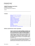
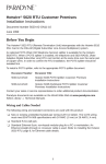
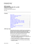
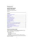
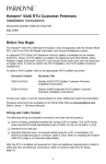
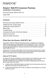
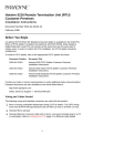
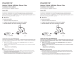
1
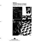
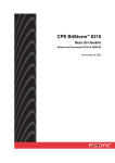
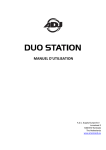
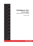
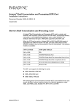
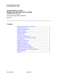
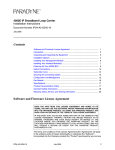
TM
Hotwire 7986 M/HDSL Standalone Termination Unit
with G.703 Interface
Installation Instructions
Document Number 7986-A2-GZ40-00
March 1999
Product Documentation on the World Wide Web
We provide complete product documentation online. This lets you search the
documentation for specific topics and print only what you need, reducing the
waste of surplus printing. It also helps us maintain competitive prices for our
products.
Complete documentation for this product is available at www.paradyne.com.
Select Library → Technical Manuals → Hotwire DSL & MVL Systems.
Select the following document:
7986-A2-GB20
Hotwire 7986 M/HDSL Standalone Termination Unit, with G.703 Interface,
User’s Guide
To request a paper copy of a Paradyne document:
Within the U.S.A., call 1-800-PARADYNE (1-800-727-2396)
Outside the U.S.A., call 1-727-530-8623
Installation Overview
Installation and configuration of the Hotwire 7986 Standalone Termination Unit
consists of:
Connecting power to the unit.
Connecting to the network.
Connecting to a DTE.
Connecting a system terminal.
Providing initial unit identity information or changing existing identity
information.
Configuring your unit using internal switchpacks or using the Configuration
Edit menus.
Before you install the Hotwire 7986 Standalone Termination Unit, read the
Important Safety Instructions on page 20.
Be sure to register your warranty at www.paradyne.com. Select Service &
Support → Warranty Registration.
7986-A2-GZ40-00
March 1999
1
Connecting Power to the Unit
If your package includes a power pack: Plug the power pack into an ac outlet
having a nominal voltage rating between 100–240 Vac. Connect the output cable
of the power pack to the connector marked POWER on the rear panel.
If your package includes a direct-connection +24 Vdc power cable: Connect the
unit to an external +24 Vdc SELV (Safety Extra Low Voltage) power source as
described in Connecting the Unit to an Optional External +24 Vdc Power Source.
If you will use a –48 Vdc power supply: Connect the unit to an external –48 Vdc
SELV power source as described in the documentation shipped with the power
supply and power cable.
Connecting the Unit to an Optional External +24 Vdc Power Source
Using the dc power cable, the Hotwire 7986 Standalone Termination Unit is
capable of operating on a +24 Vdc SELV power supply.
Procedure
To use the dc power cable:
1. Connect the green wire to a suitable ground.
2. Connect the orange wire to the +24 Vdc source.
3. Connect the white wire to the return.
4. Cut the black, red, and blue wires off at the outer insulation.
5. Plug the power connector into the 7986 Standalone Termination Unit.
Black
1
2
3
4
5
6
Red
X
X
Green
White
Orange
Blue
Ground
RTN
+24 Vdc
X
99-14158-02
+24 Vdc Power Supply Pinouts
2
March 1999
7986-A2-GZ40-00
Connecting to the Network
Procedure
To connect your unit to the network:
1. Connect one end of the supplied network cable into the rear panel DSL jack.
2. Connect the other end to your DSL network interface.
NOTE:
Do not use a flat VF network cable as this may severely degrade the
performance of the termination unit. Use only Cat 5 twisted-pair network
cable.
A crossover cable (Pins 1 and 2 to 4 and 5) is required to connect two
7986 Standalone Termination Units back-to-back.
Connecting to a DTE
The E1 network interface is either two BNC connectors (Transmit and Receive)
for a 75-ohm unbalanced interface, or an RJ48C, 8-position, unkeyed modular
connector for a 120-ohm balanced interface. See Cables and Pin Assignments in
the User’s Guide for specifications of the 120-ohm connector and cable.
Connecting to a System Terminal
An optional system maintenance terminal may be attached to your Hotwire 7986
Standalone Termination Unit through the modular jack on the rear panel. The
system maintenance terminal allows you to view the status of the unit, and
change configuration options. The terminal must be a VT100-compatible terminal
or a PC running terminal emulation software.
Procedure
To connect your unit to a system terminal:
1. Connect the 9-pin end of the terminal cable into a COM port on your PC.
2. Plug the other end into the modular jack on the rear panel.
3. Set the communication parameters on your PC or terminal to:
— 9600 baud
— 8 bit characters
— no parity
— 1 stop bit
— no flow control
Press Enter from your terminal or PC to activate the Main Menu for the attached
unit. The system runs diagnostics and status checks. After a few moments, the
Main Menu or Logon screen appears on your terminal.
7986-A2-GZ40-00
March 1999
3
Entering Identity Information
After accessing your unit for the first time, use the Change Identity screen to
determine SNMP administrative system information that will be displayed on the
Identity screen of the Status branch. To access the Identity screen, follow this
menu selection sequence:
Main Menu → Control → Change Identity
Network Configuration
The following illustration shows a network application using a 2-port Hotwire 8786
or 8784 M/HDSL Termination Unit for access concentration in a central office
(CO). A frame relay switch and a router are connected, through the termination
unit, to partner units supporting a host or router, and frame relay encapsulated or
unframed data.
G.703
CO Site
7986
Frame
Relay
Switch
2.048 Mb
over
SDSL
Router
G.703
7986
EIA-530A
V.35
7985
8786 or 8784
Termination Unit
in 8600 DSLAM
E1 Host
(Frame Relay
Encapsulated
Data)
Router
(Frame Relay
Encapsulated
Data)
Router
Customer
Premises (CP)
Customer
Premises
NTU
CO Site
LTU
7985
7986 (G.703)
V.35
7986
7986 (G.703)
G.703
98-16151
4
March 1999
7986-A2-GZ40-00
In a DSLAM-to-standalone configuration:
The devices synchronize without altering factory defaults, since the CO unit
defaults to LTU mode, and the CP unit defaults to NTU mode.
In a standalone-to-standalone configuration:
One unit must be changed to run in LTU mode, since standalone units have
a factory default setting of NTU mode.
In both cases the clocking source may have to be altered depending on network
requirements.
Choosing a Configuration Mode
You can make configuration changes either through a VT100-compatible terminal
and the unit’s Configuration menus or by manually changing switches on the
board. The unit comes configured to allow settings to be made through the
Configuration menus.
Configuring the Unit Using the Configuration Menus
Use the Configuration menu to select, display, or change configuration option
settings.
NOTE:
The 7986 Standalone Termination Unit is preconfigured as an NTU. If you
are using this unit as an NTU, the configuration options may not need to be
changed.
The 7986 Standalone Termination Unit has two sets of configuration option
settings:
The Current Configuration (the 7986 Standalone Termination Unit’s active set
of configuration options)
The Default Factory Configuration (a read-only configuration area containing
the factory default configuration options)
To display configuration options, you must first load a configuration into the edit
area. To load a configuration option set into the configuration edit area, follow this
menu selection sequence:
Main Menu → Configuration (Load Configuration From)
Make a selection by placing the cursor at your choice and pressing Enter.
7986-A2-GZ40-00
If you select . . .
Then . . .
Current
Configuration
The selected configuration option set is loaded and the
Configuration Edit/Display menu screen appears.
Default Factory
Configuration
The selected configuration option set is loaded and the
Configuration Edit/Display menu screen appears.
Configuration
Loader
The Configuration Loader screen is displayed allowing you to
upload or download configurations from a TFTP server.
March 1999
5
Configuration Edit/Display
The Configuration Edit/Display screen is displayed when the current, customer,
or default configuration is loaded. To access the Configuration Edit/Display
screen, follow this menu selection sequence:
Main Menu → Configuration → Current Configuration
– or –
Main Menu → Configuration → Default Factory Configuration
main/config/edit
Hotwire
Model: 7986
CONFIGURATION EDIT/DISPLAY
Î
Network
G.703
System Options
Communication Port
Management and Communication
ÎÎ
–––––––––––––––––––––––––––––––––––––––––––––––––––––––––––––––––––––––––––––––
Exit
Ctrl-a to access these functions, ESC for previous menu
MainMenu
Save
Select . . .
To Access the . . .
To Configure the . . .
Network
Network Interface Options, Table 1
DSL network interfaces on
the unit.
G.703
G.703 Interface Options, Table 2
G.703 interface.
System Options System Options, Table 3
General system options of
the unit.
Communication
Port
Communication Port Options, Table 4
Unit’s COM port options.
Management
and
Communication
Telnet Session Options, Table 5
Management support of the
unit through SNMP and
Telnet.
Communication Protocol Options,
Table 6
General SNMP Management
Options, Table 7
SNMP NMS Security Options,
Table 8
SNMP Traps Options, Table 9
6
March 1999
7986-A2-GZ40-00
Table 1. Network Interface Options
Margin Threshold
Possible Settings: –5db, –4db, –3db, –2db, –1db, 0db, 1db, 2db, 3db, 4db, 5db, 6db,
7db, 8db, 9db, 10db
Default Setting: 0db
Determines the level, expressed in decibels, at which a signal-to-noise margin alarm
condition is reported.
Excessive Error Rate Threshold
Possible Settings: 1E–4, 1E–5, 1E–6, 1E–7, 1E–8, 1E–9
Default Setting: 1E–6
Determines the error rate at which an excessive error rate (EER) condition is
recognized. The rate is the ratio of the number of CRC errors to the number of bits
received in a certain period.
AutoRate
Possible Settings: Enable, Disable
Default Setting: Disable
Determines whether the unit automatically adjusts to the best line rate for conditions, or
is fixed at the rate in the DSL Line Rate field.
AutoRate is only available when the unit is configured as an LTU.
DSL Line Rate
Possible Settings: 400, 528, 784, 1040, 1552, 2064
Default Setting: 2064
Determines the fixed line rate of the LTU, in kbps.
DSL Line Rate is only available when the unit is configured as an LTU, and
AutoRate is set to Disable.
Peer IP Address (LTU Only)
Possible Settings: 000.000.000.001 – 223.255.255.255, Clear
Default Setting: 000.000.000.000
Specifies the peer IP address for the NTU, to provide remote management providing the
remote management link on the DSL loop.
Peer IP Address is only available when the standalone unit is configured as an
LTU.
Circuit Identifier
Possible Settings: [ASCII Text], Clear
Default Setting: [blank]
Uniquely identifies the circuit number of the transmission vendor’s DSL line for
troubleshooting purposes.
7986-A2-GZ40-00
March 1999
7
Table 2. G.703 Interface Options
Port Status
Possible Settings: Enable, Disable
Default Setting: Enable
Determines whether the port can be configured and used.
Framing
Possible Settings: Framed, Unframed
Default Setting: Framed
Determines whether G.704 framing is used for the G.703 interface.
Line Coding Format
Possible Settings: AMI, HDB3
Default Setting: HDB3
Specifies the line coding format to be used by the G.703 interface.
Line Framing
Possible Settings: CRC4, noCRC4
Default Setting: noCRC4
Specifies the framing format to be used by the G.703 interface.
Time Slot 16
Possible Settings: Signaling, Data
Default Setting: Signaling
Specifies whether the G.703 interface is used for voice or data.
Send AIS on Network Failure
Possible Settings: Enable, Disable
Default Setting: Enable
Specifies the action taken on the signal transmitted to the G.703 when a valid signal
cannot be recovered from the network interface (LOS or cognitions OOF, AIS, or EER).
Primary Clock Source
Possible Settings: G.703, Internal
Default Setting: Internal
Specifies where the unit will derive its timing from.
Secondary Clock Source
Possible Settings: G.703, Internal
Default Setting: Internal
Specifies where the unit will derive its timing from if the primary clock fails.
8
March 1999
7986-A2-GZ40-00
Table 3. System Options
DSL Mode
Possible Settings: LTU, NTU
Default Setting: NTU
Controls whether the unit is configured as a control unit or tributary unit.
NOTE:
Changing this option will reset the unit.
Test Timeout
Possible Settings: Enable, Disable
Default Setting: Enable
Allows tests to end automatically. The feature should be enabled when the unit is
remotely managed, so that control can be regained after a test is accidentally executed.
Test Duration (min)
Possible Settings: 1–120
Default Setting: 10
Number of minutes for a test to be active before automatically ending.
G.703 Line Termination
Possible Settings: 120 Ohm, 75 Ohm
Default Setting: 120 Ohm
Determines whether the line impedance is set for 75 Ohm or 120 Ohm.
Table 4. Communication Port Options (1 of 2)
Port Use
Possible Settings: Terminal, Net Link
Default Setting: Terminal
Specifies how the communications port is to be used.
Port Type
Possible Settings: Asynchronous, Synchronous
Default Setting: Asynchronous
When Port Use is set to Net Link, Port Type controls whether the communication port
will be asynchronous or synchronous.
Data Rate
Possible Settings: 9.6, 14.4, 19.2, 28.8, 38.4
Default Setting: 9.6
Specifies the communication port baud rate.
Character Length (Terminal Use Only)
Possible Settings: 7, 8
Default Setting: 8
Determines the character length of the communication port.
7986-A2-GZ40-00
March 1999
9
Table 4. Communication Port Options (2 of 2)
Parity (Terminal Use Only)
Possible Settings: None, Odd, Even
Default Setting: None
Specifies the parity of the communication port.
Stop Bits (Terminal Use Only)
Possible Settings: 1, 1.5, 2
Default Setting: 1
Specifies the number of stop bits for the communication port.
Ignore Control Leads (Terminal Use Only)
Possible Settings: Disable, DTR
Default Setting: Disable
Specifies whether DTR is used.
Login Required (Terminal Use Only)
Possible Settings: Enable, Disable
Default Setting: Disable
Specifies if an ID and password are required to access the asynchronous terminal
interface on the communication port. Login IDs are created with a password and access
level.
Port Access Level (Terminal Use Only)
Possible Settings: Administrator, Operator
Default Setting: Administrator
Specifies the highest level of access allowed when accessing an ATI session through a
Telnet session.
Inactivity Timeout (Terminal Use Only)
Possible Settings: Enable, Disable
Default Setting: Disable
Provides automatic logoff of a Telnet session.
Disconnect Time (Minutes) (Terminal Use Only)
Possible Settings: 1 – 60
Default Setting: 5
Number of minutes of inactivity before the session terminates automatically. Timeout is
based on no keyboard activity.
10
March 1999
7986-A2-GZ40-00
Table 5. Telnet Session Options
Telnet Session
Possible Settings: Enable, Disable
Default Setting: Enable
Specifies if the Termination Unit will respond to a Telnet session request from a Telnet
client on an interconnected IP network.
Telnet Login Required
Possible Settings: Enable, Disable
Default Setting: Disable
Specifies whether a user ID and password are required to access to the ATI through a
Telnet session. Login IDs are created with a password and access level.
Session Access Level
Possible Settings: Administrator, Operator
Default Setting: Administrator
The Telnet session access level is interrelated with the access level of the Login ID.
Inactivity Timeout
Possible Settings: Enable, Disable
Default Setting: Disable
Provides automatic logoff of a Telnet session.
Disconnect Time (Minutes)
Possible Settings: 1 – 60
Default Setting: 5
Number of minutes of user inactivity before a Telnet session terminates automatically.
Time out is based on no keyboard activity.
7986-A2-GZ40-00
March 1999
11
Table 6. Communication Protocol Options
Node IP Address
Possible Settings: 000.000.000.000 – 223.255.255.255
Default Setting: 000.000.000.000
Specifies the Node IP address.
Node IP Address is only available when the standalone unit is configured as an
LTU.
Node Subnet Mask
Possible Settings: 000.000.000.000 – 255.255.255.255
Default Setting: 000.000.000.000
Specifies the Node Subnet Mask.
Node Subnet Mask is only available when the standalone unit is configured as an
LTU.
Default Network Destination
Possible Settings: None, COM, DSL
Default Setting: None
Specifies where the default management network is connected. For example, if your
default network is connected to the COM port, select COM as the default management
network destination.
Communication Port IP Address
Possible Settings: 000.000.000.000 – 223.255.255.255
Default Setting: 000.000.000.000
Specifies the unit’s Communication Port IP Address when the unit is configured as a
network communication link.
Communication Port IP Address is only used when the Port Use option on the
Communication Port Options menu is set to Net Link. If the COM Port IP address
is not set (000.000.000.000) the node IP address specified by the Node IP Port will
be used.
Communication Port Subnet Mask
Possible Settings: 000.000.000.000 – 255.255.255.255
Default Setting: 000.000.000.000
Specifies the unit’s Communication Port Subnet Mask when the unit is configured as a
network communication link.
Communication Port Subnet Mask is only used when the Port Use option on the
Communication Port Options menu is set to Net Link. If the COM Port IP address
is not set (000.000.000.000), the node IP Address will be used.
Communication Port Link Protocol
Possible Settings: PPP, SLIP
Default Setting: PPP
Specifies the unit’s Communication Port link layer protocol when the unit is configured
as a network communication link.
Communication Port Link Protocol is only used when the Port Use option on the
Communication Port Options menu is set to Net Link.
12
March 1999
7986-A2-GZ40-00
Table 7. General SNMP Management Options
SNMP Management
Possible Settings: Enable, Disable
Default Setting: Disable
Enable or disables the SNMP management features.
Community Name 1
Possible Settings: ASCII text field, Public
Default Text: Public
Identifies the name of the community allowed to access the unit’s MIB. The community
name must be supplied by an external SNMP manager when that manager attempts to
access an object in the MIB.
Name 1 Access
Possible Settings: Read, Read/Write
Default Setting: Read
Determines the access level for Community Name 1.
Community Name 2
Possible Settings: ASCII text field, Public
Default Text: Public
Identifies the name of the second community allowed to access the unit’s MIB. The
community name must be supplied by an external SNMP manager when that manager
attempts to access an object in the MIB.
Name 2 Access
Possible Settings: Read, Read/Write
Default Setting: Read
Determines the access level for Community Name 2.
7986-A2-GZ40-00
March 1999
13
Table 8. SNMP NMS Security Options
NMS IP Validation
Possible Settings: Enable, Disable
Default Setting: Disable
Specifies whether security checking is performed on the IP address of SNMP
management systems attempting to access the node.
Number of Managers
Possible Settings: 1, 2, 3, 4, 5, 6, 7, 8, 9, 10
Default Setting: 1
Specifies the number of SNMP management systems that can send SNMP messages.
NMS n IP Address
Possible Settings: 000.000.000.000 – 223.255.255.255, Clear
Default Setting: 000.000.000.000
Specifies the Internet Protocol address used to identify each SNMP trap manager.
Access Level
Possible Settings: Read, Read/Write
Default Setting: Read
Determines the access level allowed for an authorized NMS when IP address validation
is being performed.
14
March 1999
7986-A2-GZ40-00
Table 9. SNMP Traps Options
SNMP Traps
Possible Settings: Enable, Disable
Default Setting: Disable
Controls the generation of SNMP trap messages. The options for addresses and types
of traps are located in this table.
Number of Trap Managers
Possible Settings: 1, 2, 3, 4, 5
Default Setting: 1
Sets the number of SNMP management systems that will receive SNMP traps.
NMS n IP Address
Possible Settings: 000.000.000.000 – 223.255.255.255, Clear
Default Setting: 000.000.000.000
Specifies the Internet Protocol address used to identify each SNMP trap manager.
NMS n Destination
Possible Settings: DSL, COM
Default Setting: DSL
Provides the network destination path of each trap manager.
General Traps
Possible Settings: Disable, Warm, AuthFail, Both
Default Setting: Both
Determines which SNMP traps are sent to each trap manager.
Enterprise Specific Traps
Possible Settings: Enable, Disable
Default Setting: Disable
Determines if SNMP traps are generated for enterprise-specific events.
Link Traps
Possible Settings: Disable, Up, Down, Both
Default Setting: Both
Determines if SNMP traps are generated for link up and link down for one of the
communication interfaces.
Link Trap Interfaces
Possible Settings: Network, G.703, All
Default Setting: All
Determines if the SNMP linkUp, SNMP linkDown, and interface-related
enterpriseSpecific traps are generated for the network interface, G.703 interface, or
both.
7986-A2-GZ40-00
March 1999
15
Configuring the Unit Using the Internal Switches
If desired, use internal Switchpacks S1 and S2 to manually configure the unit.
! HANDLING PRECAUTIONS FOR
STATIC-SENSITIVE DEVICES
496-15104
This product is designed to protect sensitive components from
damage due to electrostatic discharge (ESD) during normal operation.
When performing installation procedures, however, take proper static
control precautions to prevent damage to equipment. If you are not
sure of the proper static control precautions, contact your nearest
sales or service representative.
Procedure
To configure the unit using internal Switchpacks S1 and S2:
1. Power down the unit and disconnect the power supply.
2. Remove the enclosure cover:
— Insert a small, flat screwdriver blade into the slots on one side of the
cover and push to free the inner latches
— Lift off the cover to expose the circuit board
3. Locate Switchpack S1.
4. Set Switch 1 on Switchpack S1 to ON to enable Switchpacks 1 and 2.
5. After you enable the switchpacks, set the switches to your desired
configuration.
6. Replace and secure the cover.
7. Power up the board to reset and enable the new configuration.
16
March 1999
7986-A2-GZ40-00
Switchpack Locations
Use the following illustration to locate Switchpacks S1 and S2.
Switchpack S1 & S2
ON
1
ON
1
Front
2
2
3
3
4
4
5 6
5 6
7
7
8
8
S2
S1
Rear
98-16073
Hotwire 7986 Standalone Termination Unit Switchpack Locations
7986-A2-GZ40-00
March 1999
17
Switchpack Definitions
Manually change configuration options by moving Switchpack S1 DIP switches
on the card. Table 10 lists Switchpack S1 definitions.
Table 10. Switchpack S1 Definitions
Switch # . . .
Allows you to . . .
1
Enable or disable Switchpacks S1 and S2.
Default in Bold
OFF = Switchpacks Disabled
ON = Switchpacks Enabled
2
Control line termination.
OFF = 120 Ohm
ON = 75 Ohm
3
Select the unit’s primary timing source. Only valid for units configured
as LTU.
OFF = Internal Clock
ON = External Clock
4
Control the unit’s E1 line coding.
OFF = HDB3
ON = AMI
5
Not used
6
Enable CRC-4 monitoring.
OFF = Enable CRC-4
ON = Disable CRC-4 monitoring
7
Control whether Channel 16 contains signaling information or data.
OFF = Channel 16 is used for signaling
ON = Channel 16 is used for data
8
18
Not used
March 1999
7986-A2-GZ40-00
Table 11 lists Switchpack S2 definitions.
Table 11. Switchpack S2 Definitions
Switch # . . .
Allows you to . . .
1
Control whether the unit is an LTU or an NTU.
Default in Bold
OFF = NTU
ON = LTU
2
Control enabling and disabling of the AutoRate capability. Only valid for
units configured as LTU.
OFF = AutoRate Disabled
ON = AutoRate Enabled
3, 4, 5
Select one of eight preset DSL line rates (refer to Table 12).
All OFF = 2064
6, 7
Not used
8
Emergency Use Only – The 7986 has two banks of flash memory
used to hold executable firmware. This switch allows you to switch
between the two versions of firmware. This switch is independent from
the position of Switch 1 on Switchpack S1 (switchpack enable/disable).
OFF = Current Firmware
ON = Previous Firmware
Use Table 12 to set the DSL Line Rate. Defaults are shown in bold.
Table 12. DSL Line Rate, Switches 3 – 5 on Switchpack S2
Switch Position
7986-A2-GZ40-00
5
4
3
DSL Line Rate
OFF
ON
ON
400 kbps
ON
OFF
OFF
528 kbps
ON
OFF
ON
784 kbps
ON
ON
OFF
1040 kbps
ON
ON
ON
1552 kbps
OFF
OFF
OFF
2064 kbps
March 1999
19
!
Important Safety Instructions
1. Read and follow all warning notices and instructions marked on the product
or included in the manual.
2. Input power to this product must be provided by one of the following: (1) a UL
Listed/CSA Certified power source with a Class 2 or Limited Power Source
(LPS) output for use in North America; or (2) a 24 Vdc National Electric Code
(NEC) ANSI/NFPA 70/Canadian Electric Code (CEC) Class 2 circuit installed
in accordance with articles 110-16, 110-17, and 110-18 of the NEC, and
articles 2-308, 2-310, 2-312, 2-314, 2-200, and 2-202 of the CEC, or (3) a
Safety Extra Low Voltage (SELV) power source with a maximum available
output of less than 240 VA, certified for use in the country of installation.
3. Slots and openings in the cabinet are provided for ventilation. To ensure
reliable operation of the product and to protect it from overheating, these
slots and openings must not be blocked or covered.
4. Do not allow anything to rest on the power cord and do not locate the product
where persons will walk on the power cord.
5. Do not attempt to install or service this product yourself, as opening or
removing covers may expose you to dangerous high voltage points or other
risks. Refer all installation and servicing to qualified service personnel.
6. General purpose cables are provided with this product. Special cables, which
may be required by the regulatory inspection authority for the installation site,
are the responsibility of the customer.
7. When installed in the final configuration, the product must comply with the
applicable Safety Standards and regulatory requirements of the country in
which it is installed. If necessary, consult with the appropriate regulatory
agencies and inspection authorities to ensure compliance.
8. A rare phenomenon can create a voltage potential between the earth
grounds of two or more buildings. If products installed in separate buildings
are interconnected, the voltage potential may cause a hazardous condition.
Consult a qualified electrical consultant to determine whether or not this
phenomenon exists and, if necessary, implement corrective action prior to
interconnecting the products.
9. In addition, if the equipment is to be used with telecommunications circuits,
take the following precautions:
— Never install telephone wiring during a lightning storm.
— Never install telephone jacks in wet locations unless the jack is
specifically designed for wet locations.
— Never touch uninsulated telephone wires or terminals unless the
telephone line has been disconnected at the network interface.
— Use caution when installing or modifying telephone lines.
— Avoid using a telephone (other than a cordless type) during an electrical
storm. There may be a remote risk of electric shock from lightning.
— Do not use the telephone to report a gas leak in the vicinity of the leak.
20
March 1999
7986-A2-GZ40-00
EMI Warnings
! WARNING:
This equipment has been tested and found to comply with the limits
for a Class A digital device, pursuant to Part 15 of the FCC rules. These
limits are designed to provide reasonable protection against harmful
interference when the equipment is operated in a commercial
environment. This equipment generates, uses, and can radiate radio
frequency energy and, if not installed and used in accordance with the
instruction manual, may cause harmful interference to radio
communications. Operation of this equipment in a residential area is
likely to cause harmful interference in which case the user will be
required to correct the interference at his own expense.
The authority to operate this equipment is conditioned by the
requirements that no modifications will be made to the equipment
unless the changes or modifications are expressly approved by
Paradyne Corporation.
! WARNING:
To Users of Digital Apparatus in Canada:
This Class A digital apparatus meets all requirements of the Canadian
interference-causing equipment regulations.
Cet appareil numérique de la classe A respecte toutes les exigences du
règlement sur le matérial brouilleur du Canada.
Warranty, Sales, Service, and Training Information
Contact your local sales representative, service representative, or distributor
directly for any help needed. For additional information concerning warranty,
sales, service, repair, installation, documentation, training, distributor locations, or
Paradyne worldwide office locations, use one of the following methods:
Internet: Visit the Paradyne World Wide Web site at www.paradyne.com.
(Be sure to register your warranty there. Select Service & Support →
Warranty Registration.)
Telephone: Call our automated system to receive current information by fax
or to speak with a company representative.
— Within the U.S.A., call 1-800-870-2221
— Outside the U.S.A., call 1-727-530-2340
7986-A2-GZ40-00
March 1999
21
Asynchronous Terminal Interface Menu
The following illustration shows the menu paths to the different terminal screens.
Main
Status
Test
Configuration
Control
Reset
Change Download
AutoRate
Code
Identity
Apply
Administer
Reset
Download Device
Logins
System and Performance Display Identity
Test Status
Statistics
LEDs
Network
Network
G.703
Error
Performance Statistics
Statistics
Statistics
Network
and
G.703 Test
Device Abort
Tests All
Tests
Network
Factory Configuration Current Configuration
Config
Loader
Edit/Display
G.703
System Communication Management
Options
Port
and
Communication
Telnet Communication General SNMP SNMP
Session
Protocol
SNMP NMS Traps
99-16071-01
Document Feedback
We welcome your comments and suggestions about this document. Please mail
them to Technical Publications, Paradyne Corporation, 8545 126th Ave. N.,
Largo, FL 33773, or send e-mail to [email protected]. Include the
number and title of this document in your correspondence. Please include your
name and phone number if you are willing to provide additional clarification.
*7986–A2–GZ40–00*
Copyright 1999 Paradyne Corporation
22
March 1999
7986-A2-GZ40-00