1
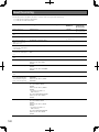
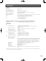
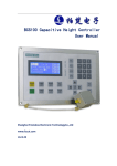
Installation Guide
Digital Disk Recorder
Model No.
ERROR
ALARM
SUSPEND
ALARM
RESET
ALARM
STS
MONITOR
HDD1 A/F
TIMER
HDD2
OPERATE
WJ-HD616K
WJ-HD716K
HDD3
1
2
3
4
5
6
7
8
0/10
11
12
SEQ
OSD
9
HDD4
MULTI SCRE
EN
13
14
15
16
STOP
GOTO LAST
SUB
MENU
PLAY PAUS
E
GOTO DATE
REC REC
STOP
REV
SEARCH
FWD
COPY
SETUP ESC
SET
HOLD
Digital Dis
k Record
er WJ-HD
616
MOUSE
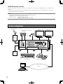
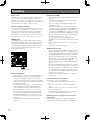
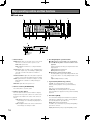
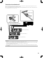
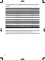
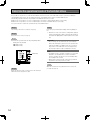
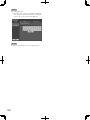
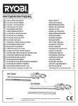
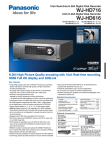
This illustration represents WJ-HD616K.
Before attempting to connect or operate this product,
please read these instructions carefully and save this manual for future use.
No model number suffix is shown in this manual.
WARNING:
• This apparatus must be earthed.
• Apparatus shall be connected to a main socket outlet with a
protective earthing connection.
• The mains plug or an appliance coupler shall remain readily
operable.
• To prevent fire or electric shock hazard, do not expose this
apparatus to rain or moisture.
• The apparatus should not be exposed to dripping or splashing and that no objects filled with liquids, such as vases,
should be placed on the apparatus.
• All work related to the installation of this product should be
made by qualified service personnel or system installers.
• The connections should comply with local electrical code.
CAUTION:
Before attempting to connect or operate this product, please
read the label on the bottom.
CAUTION:
An ALL-POLE MAINS SWITCH with a contact separation of at
least 3 mm in each pole shall be incorporated in the electrical
installation of the building.
For Canada
This Class A digital apparatus complies with Canadian
ICES-003.
CAUTION
For U.S.A.
RISK OF ELECTRIC SHOCK
DO NOT OPEN
NOTE: This equipment has been tested and found to comply with the limits for a Class A digital device, pursuant to
Part 15 of the FCC Rules. These limits are designed to
provide reasonable protection against harmful interference
when the equipment is operated in a commercial environment. This equipment generates, uses, and can radiate
radio frequency energy and, if not installed and used in
accordance with the instruction manual, may cause harmful interference to radio communications.
Operation of this equipment in a residential area is likely to
cause harmful interference in which case the user will be
required to correct the interference at his own expense.
CAUTION: TO REDUCE THE RISK OF ELECTRIC SHOCK,
DO NOT REMOVE COVER (OR BACK).
NO USER-SERVICEABLE PARTS INSIDE.
REFER SERVICING TO QUALIFIED SERVICE PERSONNEL.
The lightning flash with arrowhead symbol,
within an equilateral triangle, is intended to
alert the user to the presence of uninsulated "dangerous voltage" within the product's enclosure that may be of sufficient
magnitude to constitute a risk of electric
shock to persons.
The exclamation point within an equilateral
triangle is intended to alert the user to the
presence of important operating and
maintenance (servicing) instructions in the
literature accompanying the appliance.
Power disconnection. Unit with or without ON-OFF switches
have power supplied to the unit whenever the power cord is
inserted into the power source; however, the unit is operational only when the ON-OFF switch is in the ON position.
Unplug the power cord to disconnect the main power for all
units.
2
FCC Caution: To assure continued compliance, (example use only shielded interface cables when connecting to
computer or peripheral devices). Any changes or modifications not expressly approved by the party responsible
for compliance could void the user’s authority to operate
this equipment.
For U.S.A.
The model number and serial number of this product may
be found on the surface of the unit.
You should note the model number and serial number of
this unit in the space provided and retain this book as a
permanent record of your purchase to aid identification in
the event of theft.
Model No.
Serial No.
Limitation of liability
THIS PUBLICATION IS PROVIDED "AS IS" WITHOUT
WARRANTY OF ANY KIND, EITHER EXPRESS OR IMPLIED,
INCLUDING BUT NOT LIMITED TO, THE IMPLIED
WARRANTIES OF MERCHANTABILITY, FITNESS FOR ANY
PARTICULAR PURPOSE, OR NON-INFRINGEMENT OF
THE THIRD PARTY'S RIGHT.
THIS PUBLICATION COULD INCLUDE TECHNICAL
INACCURACIES OR TYPOGRAPHICAL ERRORS.
CHANGES ARE ADDED TO THE INFORMATION HEREIN,
AT ANY TIME, FOR THE IMPROVEMENTS OF THIS
PUBLICATION AND/OR THE CORRESPONDING PRODUCT
(S).
Disclaimer of warranty
IN NO EVENT SHALL Panasonic Corporation BE LIABLE TO
ANY PARTY OR ANY PERSON, EXCEPT FOR
REPLACEMENT OR REASONABLE MAINTENANCE OF
THE PRODUCT, FOR THE CASES, INCLUDING BUT NOT
LIMITED TO BELOW:
(1) ANY DAMAGE AND LOSS, INCLUDING WITHOUT
LIMITATION, DIRECT OR INDIRECT, SPECIAL,
CONSEQUENTIAL OR EXEMPLARY, ARISING OUT OF
OR RELATING TO THE PRODUCT;
(2) PERSONAL INJURY OR ANY DAMAGE CAUSED BY
INAPPROPRIATE USE OR NEGLIGENT OPERATION OF
THE USER;
(3) UNAUTHORIZED DISASSEMBLE, REPAIR OR
MODIFICATION OF THE PRODUCT BY THE USER;
(5) ANY PROBLEM, CONSEQUENTIAL INCONVENIENCE,
OR LOSS OR DAMAGE, ARISING OUT OF THE
SYSTEM COMBINED BY THE DEVICES OF THIRD
PARTY;
(6) ANY CLAIM OR ACTION FOR DAMAGES, BROUGHT
BY ANY PERSON OR ORGANIZATION BEING A
PHOTOGENIC SUBJECT, DUE TO VIOLATION OF
PRIVACY WITH THE RESULT OF THAT
SURVEILLANCE-CAMERA'S PICTURE, INCLUDING
SAVED DATA, FOR SOME REASON, BECOMES
PUBLIC OR IS USED FOR THE PURPOSE OTHER
THAN SURVEILLANCE;
(7) LOSS OF REGISTERED DATA CAUSED BY ANY
FAILURE.
(4) INCONVENIENCE OR ANY LOSS ARISING WHEN
IMAGES ARE NOT DISPLAYED, DUE TO ANY REASON
OR CAUSE INCLUDING ANY FAILURE OR PROBLEM
OF THE PRODUCT;
3
Important safety instructions
1) Read these instructions.
2) Keep these instructions.
3) Heed all warnings.
4) Follow all instructions.
5) Do not use this apparatus near water.
6) Clean only with dry cloth.
7) Do not block any ventilation openings. Install in accordance with the manufacturer's instructions.
8) Do not install near any heat sources such as radiators, heat registers, stoves, or other apparatus (including amplifiers) that
produce heat.
9) Do not defeat the safety purpose of the polarized or grounding-type plug. A polarized plug has two blades with one wider
than the other. A grounding type plug has two blades and a third grounding prong. The wide blade or the third prong are provided for your safety. If the provided plug does not fit into your outlet, consult an electrician for replacement of the obsolete
outlet.
10) Protect the power cord from being walked on or pinched particularly at plugs, convenience receptacles, and the point where
they exit from the apparatus.
11) Only use attachments/accessories specified by the manufacturer.
12) Use only with the cart, stand, tripod, bracket, or table specified by the manufacturer, or sold with the apparatus. When a cart
is used, use caution when moving the cart/apparatus combination to avoid injury from tip-over.
S3125A
13) Unplug this apparatus during lightning storms or when unused for long periods of time.
14) Refer all servicing to qualified service personnel. Servicing is required when the apparatus has been damaged in any way,
such as power-supply cord or plug is damaged, liquid has been spilled or objects have fallen into the apparatus, the apparatus has been exposed to rain or moisture, does not operate normally, or has been dropped.
4
Contents
Limitation of liability........................................................3
Disclaimer of warranty....................................................3
Important safety instructions..........................................4
Preface...........................................................................7
Features..........................................................................7
System configuration.....................................................8
About the user manuals.................................................9
System requirements for a PC.......................................9
Trademarks and registered trademarks.......................10
Copyright......................................................................10
Abbreviations................................................................10
Network security..........................................................11
Precautions..................................................................12
Precautions for Installation...........................................14
Major operating controls and their functions...............16
■ Front view...............................................................16
■ Rear view................................................................22
User/Host management...............................................24
Basic operation............................................................26
Operations using the buttons on the front cover.......26
Operations using a mouse.........................................26
Operations flow............................................................27
Rack mounting.............................................................28
Connections.................................................................29
Connection of cameras..............................................29
Connection of monitors..............................................30
Connection of a PC....................................................32
Connection of an extension unit................................33
Connection of a VCR..................................................34
Connection of a PS·Data compatible device.............35
Cascading connection of multiple recorders.............37
Connection of RS485 cameras..................................42
About the connectors...................................................44
How to use the terminals of the ALARM/CONTROL
connector...................................................................44
How to use the terminals of the ALARM connector...48
Time and polarities of the ALARM/CONTROL terminal
and the ALARM terminal............................................50
Mode switch...............................................................51
RS485 port.................................................................51
Install/remove HDD units..............................................52
Install the HDD units...................................................52
Remove the HDD unit................................................53
Determine the operational mode of the hard disk
drives............................................................................54
Startup..........................................................................55
Turn on the power......................................................55
Turn off the power......................................................55
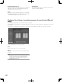
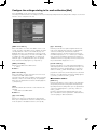
Configure the minimum settings required to use the
recorder........................................................................56
Setup menu..................................................................57
About Setup menu.....................................................58
How to operate the setup menu................................59
About the operation of on-screen keyboard
(for character entry)....................................................62
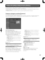
Configure the minimum settings required to
operate the recorder [Quick]........................................63
Configure the basic settings of the recorder [Basic]....65
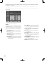
Configure the settings relating to the basic operation
of recorder [Basic]......................................................65
Configure the settings relating to time & date
[Time & date]..............................................................66
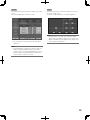
Basic settings for recording [Recording]....................68
Configure the settings relating to audio [Audio].........69
Settings for emergency recording
[Emergency rec.]........................................................70
Configure the settings relating to event [Event]...........71
Configure the common settings for event actions
[Common]...................................................................71
Configure the event action at a terminal alarm
occurrence [Terminal/Command]...............................72
Configure the event action at a camera site alarm
occurrence [Site alarm]..............................................73
Configure the event action at a video loss
occurrence [Video loss]..............................................74
Configure the event action at a VMD occurrence
[VMD]..........................................................................75
Configure the settings relating to recording/event
schedules [Schedule]...................................................79
Flowchart on how to create a schedule.....................79
Create a program [Program].......................................79
Assign a program after setting the time zone
[Time table].................................................................81
Configure the settings of recording programs for
special days [Special days]........................................82
Configure the settings relating to display [Display]......83
Common settings for monitors [Common].................83
Configure the display settings for Monitor 1
[Monitor 1]..................................................................86
Configure the display settings for Monitor 2
[Monitor 2]..................................................................88
Configure the camera title [Camera title]....................89
Configure the settings relating to the sequential
display on a PC monitor [Network]............................90
Configure the settings relating to the cascade
connection [Cascade]................................................91
Configure the settings relating to communication
with other devices [Communication]............................92
Configure the communication settings for camera
control [Camera control].............................................92
Configure the settings relating to PS·Data
[PS·Data setup]..........................................................93
Configure the settings relating to RS485
[RS485 setup].............................................................94
Configure the settings relating to the server
[Server].........................................................................95
Configure the settings relating to time adjustment
according to the NTP server [NTP]............................95
Configure the settings relating to the FTP server
[FTP]...........................................................................96
Configure the settings relating to the mail
notification [Mail]........................................................97
Configure the settings relating to network
[Network]......................................................................99
Configure the basic settings relating to a network
[Basic].........................................................................99
Configure the settings relating to DNS [DNS]..........101
Configure the settings relating to DDNS [DDNS].....102
Configure the settings relating to SNMP [SNMP]....103
Configure the Panasonic alarm protocol settings
[Panasonic alarm protocol]......................................104
Configure the settings relating to network
transmission [Transmission].....................................105
Configure the settings relating to the user
management [User mng.]...........................................106
5
Configure the basic settings relating to user
management [Basic].................................................106
Register or change the administrator information
[Administrator]..........................................................107
Register, change or delete the user information
[User]........................................................................108
Register, change, or delete a PC (host) accessible
to this recorder [Host]...............................................110
Setting of operation level [User level].......................112
Configure the settings relating to SD5 camera
[SD5Link]....................................................................113
Configure the settings relating to the i-VMD
function of SD5 camera [i-VMD setup]....................113
Uploading or downloading the settings of SD5Link
cameras [Setup data]...............................................118
Configure the settings relating to maintenance
[Maintenance].............................................................119
Check the product information such as the version
[Product information]................................................119
Confirm the available hard disk space
[Disk information].....................................................119
Confirm the network information [Network
information]..............................................................121
Configure the settings and operations relating
to hard disk drives [Disk]..........................................122
Manage the settings [Settings management]...........123
View Log Information [Logs].....................................124
Manage hard disk drives............................................126
About hard disk drives.............................................126
About the RAID 5/RAID 6 mode...............................126
Determine the operation mode................................126
About the disk configuration page...........................127
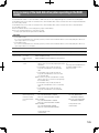
Replacement/addition of hard disk drives.................133
Replace hard disk drives..........................................133
Shutdown process of the hard disk drives...............133
Add a hard disk drive...............................................135
Auto recognition of hard disk drives........................136
Operation of the extension unit..................................138
Add an extension unit to the system........................138
Shutdown process of the extension unit..................139
About the error log.....................................................140
Error recovery of the hard disk drive (when
operating in the RAID mode)......................................145
Replacement of a faulty hard disk drive in the
RAID mode...............................................................146
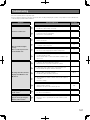
Troubleshooting..........................................................147
Check the power cord, connector and plug
periodically...............................................................152
Specifications.............................................................153
Standard accessories.................................................154
Optional Accessories.................................................154
6
Preface
The digital disk recorders WJ-HD616K, WJ-HD716K are designed for use within a surveillance system, and record images from
up to 16 cameras on the hard disk drives.
This product supports HDMI (High-Definition Multimedia Interface) standard which allows displaying playback/live images with
superior quality when connecting to a high-definition monitor using an optional HDMI cable.
It is possible to operate cameras from this product to display images from multiple cameras or switch cameras from which images are to be displayed, etc.
* No hard disk drive is supplied with this recorder. For purchasing the hard disk drive, contact your dealer.
Features
Easy operation using a PC mouse
It is possible to operate this product while monitoring a screen when directly connecting a PC mouse (commercially available) to
this product.
Image display on a High-definition monitor
It is possible to display recorded images or live images from cameras on a high-definition monitor (1 920 x 1 080).
Easy hard disk drive replacement
It is possible to install/remove hard disk drives easily into/from the recorder by opening the front cover to access the HDD slots.
When 2 or more hard disk drives are installed, it is possible to replace the hard disk drives without stopping the current recording.
Locally procured hard disk drives are to be encased in optional HDD canisters (WJ-HDU40K). At the time of shipment from the
factory, 4 canisters have been already installed in the recorder. Contact your dealer for purchasing additional HDD canisters and
hard disk drives.
HDD fault-tolerance system using the RAID function
The RAID function is available as the HDD fault-tolerance system when the optional RAID board (WJ-HD601) is installed.
In addition to the RAID 5 mode that recovers data when a single hard disk drive becomes faulty, there is RAID 6 mode that can
recover data even if 2 hard disk drives become faulty. Operation in the RAID mode is one of the solutions as the HDD fault-tolerance system that prevents data loss when handling a large amount of data on a large amount of storage.
Coordination with SD5 cameras
The following functions are available when connecting to Panasonic SD5 cameras using coaxial cables.
Refer to the operating instructions of the camera for further information about SD5 cameras.
• Alarm recording/Search and play
When the camera issued an alarm (arisen by detection of an intruder or appearance/disappearance of object), the alarm
recording will start.
Images recorded by the alarm recording can be searched and played by designating search conditions such as the alarm
type.
• i-VMD area setting
The settings of the VMD areas created from the camera and the setting of the depth compensation configured from the camera can be edited on the recorder motion detection will become more sensitive using the depth compensation. Refer to the
operating instructions of cameras for further information about the i-VMD function.
• Save and load of the setup data of the camera
The settings of the camera (setup data) can be saved on the recorder and the saved setup data can be loaded to the camera.
It is convenient when a camera goes out of order and required to be exchanged since a new camera can be used with the
same settings as it was.
7
SDHC/SD memory card slot
Images being captured at an alarm occurrence or at a network error can be saved on a SDHC/SD memory card (option) automatically.
It is also possible to directly save images on a SDHC/SD memory card. Images saved on the SDHC/SD memory card can be
played or downloaded using a web browser.
Note:
• Compatible SDHC/SD memory card (option) manufactured by Panasonic
SDHC memory card: 4 GB, 8 GB, 16 GB, 32 GB
SD memory card:256 MB, 512 MB, 1GB, 2GB
(miniSD card and micro SD card excluded)
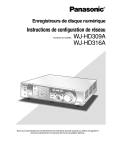
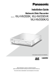
System configuration
Microphone x4
Monitor 1
System camera or combination
camera x16
Monitor 2
Amplifier
ERROR
ALARM
SUSPEND
TIMER
ALARM
RESET
ALARM
STS HDD 1
HDD 2
A/F
MONITOR
SEQ
OSD
HDD 3
OPERATE
HDD 4
MULTI SCREEN
1
2
3
STOP
PLAY
GOTO LAST
GOTO DATE
5
6
7
8
9
0/10
11
12
14
15
16
SEARCH
REC REC STOP
REV
FWD
COPY
SETUP /ESC
SUB
MENU
13
PAUSE
4
SET
HOLD
Digital Disk Recorder WJ-HD616
Powered
speaker
Extension unit x3
System controller
Network
PC
8
MOUSE
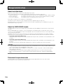
About the user manuals
The following 3 manuals are provided for the WJ-HD616K / WJ-HD716K.
Installation Guide (this document):
Contains descriptions of how to install/connect this product and how to configure
the required settings.
Operating Instructions (PDF):
Contains descriptions of how to operate this product.
(Both operations using the interface on the product and using a PC via a network are
provided)
Quick Reference Guide:
Contains descriptions of how to configure the basic settings and to operate functions
frequently used.
Adobe® Reader® is required to read the PDF files on the provided CD-ROM. When Adobe® Reader® is not installed on the PC,
download the latest Adobe® Reader® from the Adobe web site and install it.
This product is described as "HD616K" or "HD716K" in the manuals and on the setup menus.
Refer to "readme.txt" on the provided CD-ROM for further information about the optional dedicated software, compatible cameras and their versions.
A DVD drive (WJ-HDB611) and RAID board (WJ-HDB601) are optional.
When these optional products are installed, the following functions will become avaialable.
• Built-in DVD drive: Copying of recorded images and audio onto a DVD disc
Playback of recorded images and audio copied on a DVD
• RAID board:
Switching of the operational mode to RAID 5 or RAID 6 and running system with RAID 5 or
RAID 6
In these operating instructions, instructions are provided on the assumption that both the optional DVD drive and RAID board
are installed.
System requirements for a PC
It is recommended to operate this unit using a PC that meets the following system requirements.
OS:
Microsoft® Windows Vista® Business SP1 (32-bit)
Microsoft® Windows® XP Professional SP3
Microsoft® Windows® XP Home Edition SP3
OS language:
English, French, Spanish, German, Italian, Russian
CPU:
Intel® Core™2 Duo 2.66 GHz or faster
Memory:
1 GB or more (512 MB or more when using Windows® XP)
Monitor:
1 024 x 768 pixels or more, 24-bit True color or better
Network interface:
10/100 Mbps Network interface card must be installed
Web browser:
Windows® Internet Explorer® 7.0*
Microsoft® Internet Explorer® 6.0 SP3
Audio:
Sound card (When using the audio function)
Other:
CD-ROM drive: It is necessary to refer to the operating instructions on the provided CD-ROM.
DirectX® 9.0c or later
Adobe® Reader®: It is necessary to refer to the operating instructions on the provided CD-ROM.
®
* When using Microsoft Windows® Vista®
Important:
• If using a PC that does not meet the above system requirements, it may cause problems such as slow imaging or the web
browser becomes inoperable.
• Audio will not be heard if a sound card is not installed on a PC.
• Microsoft® Windows® XP Professional x64 Edition is not supported.
Note:
• Refer to "Notes on Windows Vista®" (PDF) on the provided CD-ROM for further information about system requirements for a
PC and precautions when using Microsoft® Windows Vista®.
9
Trademarks and registered trademarks
Adobe, Adobe logo and Reader are either registered trademarks or trademarks of Adobe Systems Incorporated in the United
States and/or other countries.
Microsoft, Windows, Windows Vista, Internet Explorer, ActiveX and DirectX are either registered trademarks or trademarks of
Microsoft Corporation in the United States and other countries.
Intel and Intel Core are trademarks or registered trademarks of Intel Corporation or its subsidiaries in the United States and other
countries.
HDMI, the HDMI logo and High-Definition Multimedia Interface are trademarks or registered trademarks of HDMI Licensing LLC.
SDHC logo is a trademark of the SD Card Association.
Other names of companies and products contained in these operating instructions may be trademarks or registered trademarks
of their respective owners.
Copyright
Distributing, copying, disassembling, reverse compiling, reverse engineering, and also exporting in violation of export laws of the
software provided with this product, are all expressly prohibited.
This product incorporates copy protection technology that is protected by U.S. and foreign patents, including patent numbers
5,315,448 and 6,836,549, and other intellectual property rights. The use of Macrovision's copy protection technology in the
product must be authorized by Macrovision.
Reverse engineering or disassembly is prohibited.
Abbreviations
The following abbreviations are used in this manual.
Microsoft® Windows Vista® Business SP1 (32-bit) is described as Windows Vista.
Microsoft® Windows® XP Professional SP3 and Microsoft® Windows® XP Home Edition SP3 are described as Windows XP.
Windows® Internet Explorer® 7.0 and Microsoft® Internet Explorer® 6.0 SP3 are described as Internet Explorer.
SDHC memory card and SD memory card are described as SDHC/SD memory card.
10
Network security
As you will use this product connected to a network, your attention is called to the following security risks.
q Leakage or theft of information through this product
w Use of this product for illegal operations by persons with malicious intent
e Interference with or stoppage of this product by persons with malicious intent
It is your responsibility to take precautions such as those described below to protect yourself against the above network security
risks.
• Use this product in a network secured by a firewall, etc.
• If this product is connected to a network that includes PCs, make sure that the system is not infected by computer viruses or
other malicious entities (using a regularly updated anti-virus program, anti-spyware program, etc.).
• Protect your network against unauthorized access by restricting users to those who log in with an authorized user name and
password.
• Apply measures such as user authentication for the servers and the connected devices to protect your network against leakage or theft of information, including image data, authentication information (user names and passwords), alarm mail information, FTP server information, etc.
11
Precautions
Power source
The input power source for this product is 120 V AC, 60 Hz.
Do not connect to the outlet that provides the power to
equipments that requires a measurable amount of power
(such as a copy machine, air conditioner, etc.). Avoid placing
this product in locations where is subject to water.
Ambient operating temperature
Use this product at temperatures between +5 °C to +45 °C
{+41 °F to +113 °F}. Failure to do so may damage the internal parts or cause malfunction. Performance and lifetime of
hard disk drives are easily affected by heat (used at high
temperature). It is recommended to use this product at temperatures between +20 °C to +30 °C {+68 °F to +86 °F}.
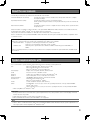
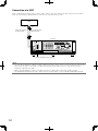
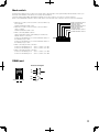
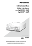
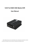
POWER switch
The POWER switch is located on the rear of this product.
Even though the POWER switch is set to "OFF", the power
supply will not be cut. To cut the power supply, unplug the
power plug of this product from the AC outlet. When using
the power supply control unit, turn off the power of the
power supply control unit.
DE
RS485(CAMERA) 10/100BASE-T
DATA
67 8
DE IN
8
8
2
1
3
1
IN
CASCADE
1
2
1
OUT MONITOR OUT(HD)
7
6
5
OUT
4
AUDIO IN
4
2 AUDIO
OUT
3
2
1
POWER
ON
7
1
OFF
OUT
7
6
5
4
3
2
AC IN
SIGNAL
GND
POWER switch
Built-in backup battery
• Before the first use, charge the built-in backup battery
(lithium battery) by turning on the power for 48 hours or
more. If it is not charged enough, in a case where the
power goes down, the internal clock may keep bad time
or the operative condition may be different to that before
the electric power failure.
• The built-in battery life is approx. 5 years as an indication
of replacement. (The built-in battery life may become
shorter depending on the use condition.)Replace the
built-in battery after 5 years of use. ("5 years of use" is
just an indication of replacement. We are not providing
any guarantee of the built-in battery lifetime.)When the
built-in battery life runs out, some settings such as the
time and date setting will not be saved once the power
is turned off.
• Ask your dealer when replacement of the battery is
required.
12
Hard disk drive (HDD)
• Hard disk drives are vulnerable to vibration. Handle them
with care.
It is possible to damage them if they are moved while
their motors are still running.
• Do not move them just after turning the power off (for
around 30 seconds).
• The lifetime of hard disk drives is limited by use. Write
errors may occur frequently after around 20 000 hours of
operation, and the head and motor deterioration may
occur after around 30 000 hours of operation. They will
reach the end of their lifetime after 30 000 hours of operation if they have been used at the recommended ambient temperature (approx. +25 °C {+77 °F})
• It is recommended to replace them after around
18 000 hours of operation to prevent data loss from disk
failures.
• When hard disk drive trouble occurs, replace it immediately.
Contact your dealer about servicing.
SDHC/SD memory card
• When using an unformatted SDHC/SD memory card,
format it using this product. Data on a SDHC/SD memory card will be deleted when it is formatted. When using
an unformatted SDHC/SD memory card or a SDHC/SD
memory card formatted using a device other than this
product, it may not work correctly or performance of this
product may be deteriorated. Refer to Operating
Instructions (PDF) for how to format a SDHC/SD memory card.
• When using a SDHC/SD memory card, it is recommended to use one manufactured by Panasonic. Please be
forewarned that any loss of information, such as images,
on a SDHC/SD memory card is not guaranteed under
any circumstances if a SDHC/SD memory card of other
manufacturer's. (+ Page 8)
• Refer to page 18 for how to insert/remove a SDHC/SD
memory card.
Prevent condensation from forming
If this happens, it can cause malfunction.
Leave it switched off for around 2 hours in the following
cases.
• When this product is placed in an extremely humid
place.
• When this product is placed in a room where a heater
has just been turned on.
• When this product is moved from an air-conditioned
room to a humid and high-temperature room.
When this product is not supposed to be used for a
certain period
Turn on the power (approx. once a week), and perform
recording/playback to prevent interferences with functions.
Cleaning
• Turn the power off, and then use a soft cloth to clean
this product. When the dirt is hard to remove, use a mild
detergent and wipe gently. Wipe out the detergent completely using a soft cloth.
• Do not use strong or abrasive detergents when cleaning
the body.
• When using a chemical cloth for cleaning, read the caution provided with the chemical cloth product.
Indication label
Refer to the indication label placed on the surface of this
product as to the indications of equipment classification and
power source, etc.
AVC patent portfolio license
This product is licensed under the AVC Patent Portfolio
License for the personal and non-commercial use of a consumer to (i) Encode video in compliance with the AVC
Standard ("AVC video") and/or (ii) Decode AVC video that
was encoded by a consumer engaged in a personal and
non-commercial activity and/or was obtained from a video
provider licensed to provide AVC video. No license is granted
or shall be implied for any other use. Additional information
may be obtained from MPEG LA, L.L.C.
See http://www.mpegla.com.
GPL/LGPL
• This product contains software licensed under GPL
(GNU General Public License), LGPL (GNU Lesser
General Public License), etc.
• Customers can duplicate, distribute and modify the
source code of the software under license of GPL and/or
LGPL.
• Read the "readme.txt" the provided CD-ROM for further
information about the software.
• Please note that Panasonic shall not respond to any
inquiries regarding the source code.
Handle this product with care.
Do not strike or shake, as this may damage this product.
Do not strike or give a strong shock to this product.
It may cause damage or allow water to enter this product.
13
Precautions for Installation
This product is designed for indoor use.
Avoid the following locations for installation.
• Locations exposed to direct sunlight
• Places subject to having strong vibration or impact
• Near magnetic field sources such as a television or
speakers
• Place where condensation forms easily, where temperature changes greatly, humid places
• Steamy and oily places such as kitchens
• Places which are not level
• Places subject to dust
• Places subject to water splash or spray
Do not install this product in locations where the product or the cables can be destroyed or damaged by
persons with malicious intent.
Heat dissipation
Refer to the following to prevent fire and malfunction of this
product.
• Do not block the ventilation openings in the cover to prevent this product from overheating. Maintain this product
periodically to prevent dust from blocking openings.
• A lifetime of cooling fans is limited by use. It is recommended to replace them after approx. 30 000 hours of
operation. Contact your dealer for replacement of the
cooling fans.
• Clear a space of more than 5 cm from both sides, the
top and the rear of this product. Do not block the ventilation openings on the front cover since this product is
designed to cool the hard disk drives by inhaling air from
the front.
Place this product horizontally on a level surface.
Do not place this product in an upright position. When
stacking multiple recorders, clear a space of more than 5 cm
{1-31/32"} from both sides, the top, the bottom and the rear
of them.
More than
5 cm {1-31/32"}
More than
5 cm {1-31/32"}
More than
5 cm {1-31/32"}
Avoid placing the unit near noise sources
If the cables are placed near noise sources such as fluorescent lamps, noises may be produced. In this case, rewire
avoiding the noise sources, or move this product to a place
far from the source.
Power source
A grounding connection must be made before connecting
the power plug of this product to the main power supply.
When disconnecting the grounding wire, make sure that the
power plug of this product is disconnected from the main
power supply.
How to mount the power cord
Be sure to connect the power cord via any of the following
breaking devices:
• Connect the power cord via a power supply control unit.
• Install the product near a power outlet, and connect the
power cord via the power plug.
• Connect the power cord to the breaker with contact gap
of 3.0 mm or more of a distribution board. The breaker
shall be able to shut down all the poles of the main
power supply except the ground protective conductor.
14
For BNC cable connection
Use only the recommended plug below when connecting the
BNC plug to the connectors on the rear panel of the recorder.
BNC cable (locally procured)
Applicable plug: MIL-C39012C or MIL-C39012/16F
* Suffixes attached to the standards may be updated.
BNC cable (locally procured)
Plug
Plug
Tip dimensions inside the recommended BNC plug
ø1.32 mm - ø1.37 mm
ø1.32 mm - ø1.37 mm
ø0.13 mm - ø0.69 mm
Important:
• A compatible
plug mm
shall be used. Failure to observe this
ø0.13 mm - ø0.69
may cause trouble such as poor contact. At worst, the
connector of this product may be damaged.
Avoid placing receptacles that contain liquids such as
water near this product.
If liquid spills onto this product, it may cause fire or an electric shock.
Grounding
Confirm that the wire is connected from the SIGNAL GND
terminal to earth ground.
A grounding connection must be made before connecting
the power plug or this product to the main power supply.
When disconnecting the grounding wire, make sure that the
power plug of this product is disconnected from the main
power supply.
15
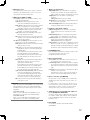
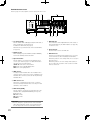
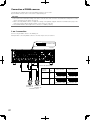
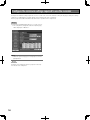
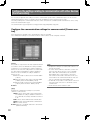
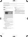
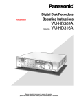
Major operating controls and their functions
■ Front view
q
w
ERROR
ALARM
SUSPEND
ALARM
RESET
ALARM
STS HDD 1
TIMER
A/F
HDD 2
e
MONITOR
SEQ
OSD
HDD 3
OPERATE
HDD 4
MULTI SCREEN
1
2
r
3
STOP
PLAY
GOTO LAST
GOTO DATE
PAUSE
6
7
8
9
0/10
11
12
SEARCH
REV
15
FWD
COPY
MAINTENANCE
SET
16
HOLD
Digital Disk Recorder WJ-HD616
i
o
!4
!1
!0
ESC
SET
u
y
SETUP /ESC
SUB
MENU
14
REC REC STOP
4
5
13
t
!2
STS A/F
MOUSE
MOUSE
!3
STS A/F
STS A/F
STS A/F
MAINTENANCE
MOUSE
SDHC/SD memory
card slot
VIDEO OUT
AUDIO OUT
!5
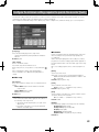
q Status indicator
ERROR: Blinks when an error that can become a problem for the recorder to run the system occurs.
Blinks red: System error
Blinks orange: Thermal error, cooling fan malfunction, etc.
ALARM: Blinks when an alarm occurs, and lights when
the alarm output stops. The blinking or lighting indicator will go off when the alarm reset button is
pressed.
ALARM SUSPEND: Lights when the alarm suspension
mode is selected. (☞ Operating Instructions (PDF))
TIMER: Lights when the schedule recording is set, and
blinks while the schedule recording is being performed.
OPERATE: Lights when the power is on.
w Alarm reset button [ALARM RESET]
Press this button to reset the alarm.
e Camera selection button
Press the desired camera selection button to display
images from the respective camera. The camera selection button also indicates the status of the camera as
follows.
Lights green: Indicates the camera channel from
which images are currently being displayed on
the monitor.
Lights orange: Indicates the camera channel from
which images are being recorded.
16
r Recording/Playback operation button
[■ STOP] button: Press this button to stop playback.
[B PLAY h PAUSE] button: Press this button to start
playback.
Playback will be paused by pressing this button during playback.
Lights green: During playback
Blinks green: During pause
[● REC] button: Starts manual recording
Recording will be stopped by holding down this button (for more than 2 seconds) during manual recording.
Lights orange: During recording
t Jog dial (inside)/Shuttle ring (outside)
Jog dial: The following functions are provided.
Frame by frame playback can be performed during
pausing.
Skip can be performed during playback.
Shuttle ring: The following functions are provided.
Fast forward/reverse playback can be performed during
playback.
y Hold button [HOLD]
Press this button during fast forward/reverse playback
started by the shuttle ring to hold the current playback
speed (hold playback speed function).
Blinks green: During hold playback
In addition, press this button to perform panning/tilting
operation of cameras.
Lights green: During low-speed panning/tilting control
u Maintenance port
The maintenance port that can be used for connection
with a PC is provided inside the cover. Do not use for
any operation other than maintenance.
i HDD indicator [HDD1 to HDD4]
STS (status): Indicates the operational statuses of the
respective hard disk drive.
Lights green: Indicates that the power of the
respective hard disk drive (formatted) is on.
Blinks green: Indicates that the respective hard disk
drive is for playback use only. (Recording is
unavailable using the respective hard disk drive.)
Blinks orange: Indicates that the respective hard
disk drive is currently being formatted.
Lights red: Indicates that formatting of the respective hard disk drive has failed.
Off: Indicates that the power of the respective hard
disk drive is off, or that the hard disk drive is not
connected/recognized.
A/F (HDD access/failure): Indicates the status (access/
failure) of the respective hard disk drive.
Blinks green: Indicates that the respective hard disk
drive is being accessed.
Lights red: The respective built-in hard disk drive is
faulty (which can be recovered by replacing the
hard disk drive).
In the RAID 5 mode, it indicates that the respective hard disk drive is the first faulty drive.
In the RAID 6 mode, it indicates that the respective hard disk drives are the first and second
faulty drive.
Blinks red: The respective built-in hard disk drive is
faulty (which cannot be recovered even by
replacing the hard disk drive).
In the RAID 5 mode, it indicates that the respective hard disk drive is the second faulty drive.
In the RAID 6 mode, it indicates that the respective hard disk drive is the third faulty drive.
Lights red and orange alternately: Indicates that the
respective hard disk drive is currently being
recovered in the RAID 5/RAID 6 mode. (It may
appear that the indicator lights orange when
recovery is being processed at high speed.)
Off: Indicates that the respective hard disk drive is
not being accessed.
Important:
When operating in the RAID5/RAID6 mode and the HDD
indicator lights red, replace the faulty hard disk drive
promptly. Contact your dealer for replacement of hard
disk drives.
In the RAID 5 mode:
When 2 or more HDD indicators light/blink red, it is
impossible to recover data on the faulty hard disk.
In the RAID 6 mode:
When 3 or more HDD indicators light/blink red, it is
impossible to recover data on the faulty hard disk.
o Monitor operation button
[MONITOR] button: Press this button to change the
monitor to be operated. The monitor number will
light to indicate the monitor currently being selected.
[SEQ] button: Press this button to start/stop the
sequence.
Lights green: During sequence display
[OSD] button: Press this button to display/hide information such as the camera title.
[MULTI SCREEN] button: Every pressing this button to
change the display pattern of multi-screen.
!0 Playback control function button
[GOTO LAST] button: Press this button to jump the
playback point to the top of the latest recorded
image.
[GOTO DATE] button: Press this button to designate
time and date of recorded images to be played.
[SEARCH] button: Press this button to play recorded
images after searching recording events.
Lights green: During search playback
[COPY] button: Press this button to display the menu on
which it is possible to copy recorded images onto a
DVD (when using an optional DVD drive) or a SDHC/
SD memory card. (☞ Operating Instructions (PDF))
!1 [SUB MENU] button
Press this button to display the submenu used for camera operation and the electronic zoom.
(☞ Operating Instructions (PDF))
!2 Menu operation button
Arrows button: Use this button to move the cursor on
the setup menu, the search menu, etc.
[SETUP/ESC] button: Hold down this button to display
the setup menu. When the setup menu is being displayed, press this button to go back to the previous
page.
[SET] button: Press this button to determine the edited
settings on the setup menu.
This button also can be used to turn the alarm suspension on/off. (☞ Operating Instructions (PDF))
!3 Mouse connection port [MOUSE]
Use this port to connect a USB mouse (commercially
available). (No device other than a mouse can be connected.)
* It is impossible to connect a mouse to the mouse connection port if the connector from the mouse is upside
down. When it is hard to connect, check the upside
down position of the connector from the mouse.
!4 SDHC/SD memory card slot/External output connector (AUDIO OUT, VIDEO OUT)
The video output connector (RCA pin jack) to be used
for output to a VCR, audio output connector (RCA pin
jack) and SDHC/SD memory card slot are provided
inside the cover.
!5 Built-in DVD
It is possible to install an optional built-in DVD
(WJ-HDB611).
17
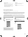
Insert an optional SDHC/SD memory card
Step 1
Insert a DVD disc (commercially available)
Step 1
Open the SDHC/SD memory card slot.
Pull the tab
down.
Open the DVD drive cover.
Pull the tab down.
SDHC/SD memory
card slot
Step 2
Step 2
Insert a SDHC/SD memory card to the slot until it clicks.
When inserting a SDHC/SD
memory card, confirm that the
label on the SDHC/SD memory
card is upside and only the
upper right corner of the card
has different shape.
Step 3
Close the cover of the SDHC/SD memory card slot.
Note:
• When removing the SDHC/SD memory card from the
slot, push the card until it clicks and pull it up straight.
After confirming that the power of the recorder is on, press
the eject button located at the center of the DVD drive and
pull the disc tray gently.
Eject button
Note:
• After copying the recorded data on a DVD, perform the
procedure to eject the DVD. (☞ Operating Instructions
(PDF))
Otherwise, the tray may not open even after the eject
button is pressed.
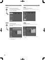
Step 3
Place a disc with the label side up and fit the hole of the disc
to the center (spindle) of the tray. Then, push the tray gently.
Click sound will be heard and the inserted disk will be set.
Spindle
18
Step 4
Push the tray to the end. Click sound will be heard and the
tray will be fixed.
Step 5
Close the DVD drive cover.
Important:
• When opening/closing the DVD drive tray, do not apply
force on the tray.
• When not using the DVD drive, close the disc tray.
• When removing the disc from the tray, press the spindle
to detach the disc. If trying to detach the disc forcibly, it
can damage both the disc and the DVD drive.
19
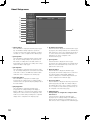
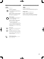
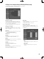
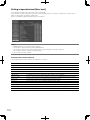
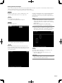
Behind the front cover
Refer to page 21 for descriptions of how to detach the front cover.
q w
e
t
r
ERROR
ALARM
SUSPEND
TIMER
ALARM
RESET
ALARM
USE
STS A/F
STS A/F
STS
STS A/F
HDD 1 A/F
HDD 2
HDD 3
OPERATE
STS A/F
RAID
ESC
MAINTENANCE
SET
HDD 4
MOUSE
y
q Use button [USE]
Use this button when adding/replacing the HDD units, or
when changing the operational mode.
Install/remove HDD units (☞ page 52)
Determine the operational mode of the hard disk drives
(☞ page 54)
w Dummy board
When installing an optional RAID board (WJ-HDB601),
remove the dummy board and install it.
e Operation button
Use this button to operate the menu during the front
cover is open. Refer to page 17 for further information
about the menu operation button.
CDA B: Same as the arrows button
ESC: Same as the [SETUP/ESC] button
SET: Same as the [SET] button
r HDD canister
Locally procured hard disk drives are installed in these
canisters. Refer to page 133 for how to add/replace the
hard disk drives. Contact your dealer about purchasing
hard disk drives.
t HDD canister slot
At the time of shipment from the factory, 4 canisters
have been already installed in these slots. Up to 4 hard
disk drives can be installed.
y RAID switch [RAID]
Use this switch to change the operational mode of the
hard disk drives (Single/RAID5/RAID6). (☞ Page 54)
S: Single mode
R5: RAID 5 mode
R6: RAID 6 mode
Default: S
20
Important:
• Do not change the operational mode of the hard disk
drives after running the system. If it is changed, it may
become impossible to read recorded data correctly.
u i
o
u HDD indicator
These indicators will not light/blink. Check the status of
the hard disk drives by the HDD indicators (+ page 16)
on the front cover.
i Removal knob
Use this knob to remove an HDD unit.
o HDD unit brace
This brace is provided for transportation. It is necessary
to remove this brace when installing hard disk drives.
When this product is to be transported, it is necessary to
attach the brace.
When this product is not to be transported anymore, it
does not affect the operation of the recorder even with
the brace attached.
How to detach the front cover
Step 1
(When detaching the front cover while the power is on)
Hold down the [ALARM RESET] button and the [MONITOR]
button (for more than 2 seconds).
→ The power of the front cover will be turned off.
Cable clamp
Connection
cable
Step 2
Open the maintenance port cover and the DVD drive cover,
and then remove the fixing screws (x3).
Connector
Note:
• Before disconnecting the cable, be sure to turn off the
power of front cover.
How to attach the front cover
Step 1
DVD drive cover
Maintenance port cover
(Pull up the bottom side
of cover.)
Step 3
Pull the right side of the front cover first, and then detach the
front cover.
Connect the connection cable of the front cover.
When connecting the connection cable, twist the connection
cable around the tab of the cable clamp.
(☞ Reference illustration for step 4 of "How to detach the
front cover")
Step 2
Put the tab (on the left of the front cover) into the hole, and
then attach the front cover.
Hole
Tab
Step 4
Disconnect the connection cable of the front cover.
• Detach the cables from the cable clamp on the front
cover.
• Disconnect the cable while holding down the tab of the
connector.
Step 3
Fasten the detached screws (x3), and then close the cover.
Step 4
(When attaching the front cover while the power is on)
Press the [ALARM RESET] button.
→ The power of the front cover will be turned on.
21
Note:
• After attaching the front cover to the recorder, be sure to
turn on the power of front cover.
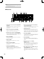
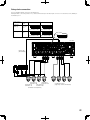
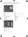
■ Rear view
q
w
e r
MODE
EXT STORAGE
3
t
2
1
y u
DATA
RS485(CAMERA) 10/100BASE-T
123 4567 8
2
ALARM
16
15
14
13
3
CASCADE
2
11
1
CASCADE IN
OUT-CASCADE-IN
12
1
IN
2
ALARM/CONTROL
i
1
1
MONITOR
OUT
10
9
8
2
1
OUT MONITOR OUT(HD)
7
6
5
OUT
4
AUDIO IN
4
2 AUDIO
OUT
3
2
1
POWER
IN
ON
7
1
16
!2
!3
15
14
13
12
11
10
9
VIDEO
!4
q Alarm/Control connector (D-sub 25-pin) [ALARM/
CONTROL]
Connect a control switch to control the recorder using
an external device such as a buzzer or a lamp.
(☞ Page 44)
w Alarm connector (D-sub 25-pin) [ALARM]
Connect an external device such as a sensor, door
switch, etc. to this connector. (☞ Page 48)
e External storage connector 1-3 [EXT STORAGE]
Connect the optional extension unit (WJ-HDE400) to this
connector using the dedicated connection cable provided with the extension unit. (☞ Page 33)
r Mode switch [MODE]
Determine the operational mode of the recorder using
this switch. (☞ Page 51)
t DATA port [DATA]
Connect a PS·Data compatible device to this port.
(☞ Page 35)
y RS485 port [RS485/CAMERA]
Connect an RS485 combination camera to this port.
(☞ Page 42)
u Network port [10/100BASE-T]
Connect this recorder to a network (10BASE-T/
100BASE-TX) using this port. When the recorder is connected to a network, it is possible to operate the recorder from a PC via a network.
22
OFF
OUT
OUT
8
7
6
5
4
3
AC IN
!5
!6
!0
2
!7 !8
SIGNAL
GND
!1
o
i Audio cascade input/output connector (RCA pin
jack) [CASCADE IN, OUT])
Use this connector for audio output from another recorder when it is connected in cascading connection.
o SIGNAL GND terminal
Connect this terminal to the SIGNAL GND terminals of
the devices in the system for signal ground. When operating the recorder and the devices in the system without
signal ground, oscillation or noise may be produced.
!0 Power button [POWER]
Press this button to turn on/off the power of the recorder. When this button is pressed again, the operation is
finished and the power is turned off.
!1 Power inlet [AC IN]
Connect the provided power cord to this inlet. The
power plug is a 2-conductor plug with grounding terminal type.
!2 Video input connector 1 to 16 (BNC)
[VIDEO IN 1 to 16]
Connect system cameras and combination cameras to
these connectors. When connecting combination cameras, connect them to the video input connector 1-8
(coaxial communication compatible).
!3 Video output connector 1 to 16 (BNC, active loop
through) [VIDEO OUT 1 to 16]
Images input to the video out connectors 1-16 will be
output from these connectors. When the power is off,
images will not be output to the video output connector
1-16.
!4 Monitor output connector (BNC) [MONITOR OUT
1, 2]
Connect a monitor to this connector. Monitor output
connector 1 shall be used to connect a monitor (Monitor
1) to display live image only. Monitor output connector 2
shall be used to connect a monitor (Monitor 2) to display
live/recorded images and the setup menus. Monitor output connector 2 can also be used for cascade output.
!5 Cascade input connector (BNC/HDMI) [CASCADE
IN 1, 2]
Connect the other recorder in cascading connection
(output) when connecting multiple recorders.
!6 Monitor output connector (HDMI) [MONITOR OUT
(HD) 1, 2]
This connector functions in the same manner as the
monitor output connector (BNC).
!7 Audio input connector 1-4 (RCA pin jack) [AUDIO
IN 1 to 4]
Use this connector for LINE input. A device such as a
microphone amplifier can be connected to input audio.
The entered audio will be output from the audio output
connector.
!8 Audio output connector (RCA pin jack) [AUDIO
OUT 1, 2]
Use this connector to output audio. Audio entered to the
audio input connector will be output from this connector.
When playing recorded images, audio recorded together
with images will be output. When the recorders are connected in cascading connection, audio from them are
also be output.
How to use the power cord plug brace
Brace the power cord plug.
Step 1
Fix the power cord plug firmly with the power cord plug
brace.
POWER
ON
OFF
Power cord plug brace
23
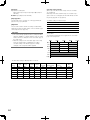
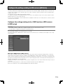
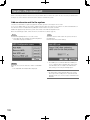
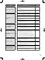
User/Host management
It is necessary to register users who operates the recorder and hosts (PC) that accesses the recorder via a network such as a
LAN. Up to 32 users and up to 8 hosts can be registered.
The following information can be registered as user information and host information.
Item
Description
Remarks
User name
User name is to be registered to log in to the recorder.
It will be required to log in to the recorder.
This setting item can be configured only in
the user registration.
IP address
IP address of a PC is to be registered to access the
recorder. When "On" is set for "Host registration", only
PCs with the registered IP addresses can access the
recorder.
This setting item can be configured only in
the host registration.
Password
Password is to be registered to log in to the recorder
together with the user name. It will be required to log in
to the recorder.
This setting item can be configured only in
the user registration.
Level
Level indicates availability of the functions for users.
Refer to page 112 for the operable functions for each
level.
Priority level
Priority level indicates the operational priority. When
multiple users/hosts tried to operate the same, only a
user/host with a higher priority can operate.
Default screen
Camera channels from which live images are to be
displayed on Monitor 1, Monitor 2 and the PC monitor
just after the login can be determined.
Camera partitioning
Operational range of each camera channel for users/
hosts can be determined.
In the following cases, the operational right
will be given to a user/host with a higher
priority.
• When another user tried to log in while
the other user is already being logged
in.
• When another user tried to control a
camera that is being controlled by the
other user
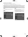
Users and hosts will be handled differently depending on how to access the recorder (between when the recorder is directly
operated and when the recorder is operated via a network).
When operating the recorder directly
Operate the recorder while monitoring the monitor connected to the recorder. There are 3 ways of how to operate the recorder
directly.
• Operate using the buttons on the front cover of the recorder.
• Operate using a mouse connected to the front cover of the recorder.
• Operate from a PS·Data compatible system controller.
Note:
• When controlling a camera connected to a coaxial communication unit from a system controller compatible with PS·Data, the
priority level configured on the recorder will not be applied since it is controlled directly from the system controller. (The priority
will be given to the latest operation.)
It is impossible to log in to the recorder from the front cover (using the buttons or the mouse) and from the system controller at
the same time (except logging in using the same user name).It is impossible to log in to the recorder regardless of the priority
level even if a user tried to log in when another user is already logged in.
24
Note:
• When operating from a system controller compatible with PS·Data, log in to the recorder automatically as the user registered
in "PSD user" on the "Basic" tab under "User mng.".
• When no operation is made for approx.2 minutes after logging in from a system controller compatible with PS·Data, the PSD
user will automatically be logged out.
• When trying to log in as the same user name used by a user who is already logged in, both users will be authorized to log in
regardless of the priority level.
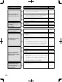
When operating from a PC via a network
Operation of the recorder can be made using a PC via a network. Up to 8 hosts (PCs) can access the recorder concurrently.
When trying to log in to the recorder even though 8 hosts (PCs) are already accessing the recorder, the host (PC) with the lowest
priority will forcibly be logged out.
When accessing the recorder from a PC via a network, the authentication method is different depending on the "User authentication" and "Host authentication" settings of the "Basic" tab under "User mng.".
User authentication
setting
Host authentication
setting
User/Host to log in
Remarks
Off
Off
Log in as an administrator.
On
Off
Log in as a registered user.
The login window will be
displayed.
Off
On
Log in as a registered host.
The login window will not
be displayed.
On
On
Log in as a registered user.
It is impossible to log in to
the recorder from an
unregistered PC.
25
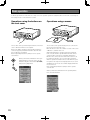
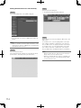
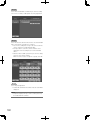
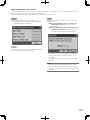
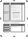
Basic operation
To directly operate the recorder, there are 2 ways of how to operate it: operations using the buttons on the front cover and operations using a mouse connected to the recorder.
Operations using the buttons on
the front cover
Operations using a mouse
Digital Disk
Digital Disk
D616
Recorder
WJ-H
D616
The recorder can be operated using the buttons on the front
cover to which the functions are assigned.
Refer to the "Major operating controls and their functions"
section (☞ page 16) for further information about the functions assigned to each button.
Refer to Operating Instructions (PDF) for how to operate
each function.
SET
Recorder
WJ-H
When you find "Select XX button" in the operating instructions, move the cursor onto the
XX button using the arrows button (CDAB)
and press the [SET] button.
The recorder can be operated using a mouse connected to
the mouse port on the front cover.
Move the mouse cursor onto a button or a tab on the screen
of Monitor 2, and then click on it
When right-clicking, the operation panel representing the
front cover (the monitor operation button and the camera
selection button on the front cover) will be displayed on
Monitor 2.The camera selection and monitor selection can
be made by moving the cursor on the button and click it.
When no operation is made for 10 seconds while the operation panel or the setup menu is displayed, the mouse cursor
will disappear. The mouse cursor will be displayed when the
mouse is moved.
Refer to Operating Instructions (PDF) for how to operate
each function.
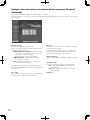
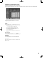
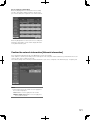
When you find “Select XX button" in the operating instructions, click the XX button.
26
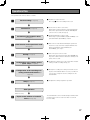
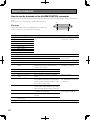
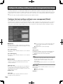
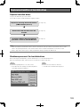
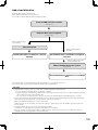
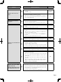
Operations flow
The operation flow of the recorder is as follows.
x
Connections (☞ Page 29)
c
Installation of the hard disk drives
v
Determination of the operational mode
b
Startup (☞ Page 55)
n
Configuration of the settings for the
quick setup. (☞ Page 63)
m
Configuration of the recording area
setting of the hard disk drives. (☞
➜
z
Rack mounting (☞ Page 28)
➜
(☞ Page 52)
➜
(☞ Page 54)
z Install the recorder in the rack.
Go to step x when not installing it in the rack.
x Connect the recorder to each device.
When using an optional extension unit, install hard disk
drives in the optional extension unit (WJ-HDE400) and
connect to the recorder. (☞ Page 33)
c Install hard disk drives in the recorder.
When using an optional RAID board (WJ-HDB601) or an
optional DVD drive (WJ-HDB611), install it.
➜
v Reboot the recorder after determining the operational
mode if necessary such when using the RAID function.
When not installing an optional RAID board
(WJ-HDB601), go to step 5.
➜
b Turn on the power of the recorder.
When using optional extension units (WJ-HDE400), turn
the power of all the extension units before turning on the
power of the recorder.
n Configure the settings such as the current time and date
setting, schedule recording settings, etc.
➜
Page 126)
➜
,
Setup (☞ Page 57)
m Change the recording area setting or format the recording area of the hard disk drive if necessary such when it
is necessary to assign the event recording area to the
hard disk drive.
, Configure the settings required for operation.
➜
Start operation
.
➜
When necessary
Replacement/addition of hard disk
drives (☞ Page 133)
The hard disk drives can be formatted/replaced without turning off the power of the recorder even when one of them
becomes faulty.
27
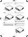
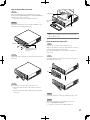
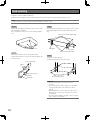
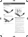
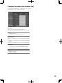
Rack mounting
Install the recorder in an EIA standard rack.
Equivalent to EIA standard rack (not manufactured by Panasonic): EIA 19-inch rack type (Depth: 550 mm or more)
Note:
• Use four M5 x 12 screws (locally procured) to install the recorder in a rack.
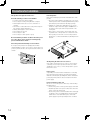
Step 1
Step 3
Remove the five rubber feet from the bottom of the recorder
using a flathead screwdriver.
Use a screwdriver to remove the screws holding the rubber
feet.
Place the rack mount brackets on both sides of the recorder.
Fix them firmly with the rack mount bracket fixing screws
(x6).
Screw for rack mount bracket (provided)
Remove the rubber feet.
Rack handle
Rack handle
Rack mount bracket (provided)
Step 2
Attach the rack handles to the rack mount brackets.
Fix them firmly using the screws for the rack handle (x4) and
the washers (x4).
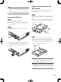
Step 4
Install the recorder in the rack.
Fix them firmly using the rack mount screws.
Screw for rack handle
Washer
Rack mount bracket
Washer
Rack handle
28
Rack mount screws
M5 x 12 (locally procured)
Important:
• Keep the temperature in the rack below +45 °C
{+113 °F}.
• It is recommended to install cooling fans or equivalents
to keep the temperature in the rack below +30 °C
{+86 °F}.
• When installing the recorder in the rack, make a space of
1U (44 mm {1-23/32"}) above and below the recorder
for ventilation.
• Do not block the ventilation openings or slots to prevent
the recorder from overheating.
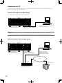
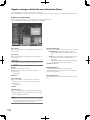
Connections
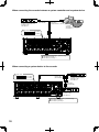
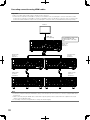
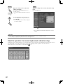
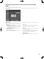
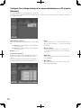
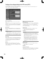
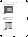
Connection of cameras
Up to 16 cameras (system cameras or combination cameras) can be connected to the video input connector 1-16.
Important:
• When using with a Panasonic's matrix switcher or a coaxial communication unit, make sure that the loop-through output
connection (of each video input) to the recorder are correctly made. When a monitor output or a spot output is connected to
the video input connector of the recorder, noise may be produced upon switching camera channels or images of few seconds before switching camera channels may be displayed/recorded. When a monitor output or a spot output is connected to
the video input connector of the recorder, noise may be produced upon switching camera channels or images of few seconds before switching camera channels may be displayed/recorded.
• Connect the power plug of the recorder at the very end of connections.
• When connecting combination cameras to the WJ-HD616K, connect them to the video input connector 1 - 8 (coaxial connection compatible).
• It is impossible to connect a VCR to the video input connector.
Mode switch setting (default)
Note:
• When not using the DATA port and the RS485 port, do not change the setting from the default.
Mode switch setting (default)
Microphone
ON
1 2 3 4 5 6 7 8
Amplifier
Note: When not using the DATA port and the RS485
port, do not change the setting from the default.
Recorder
MODE
EXT STORAGE
3
2
1
DATA
RS485(CAMERA) 10/100BASE-T
123 4567 8
2
1
1
MONITOR
OUT
ALARM
15
14
13
CASCADE
2
11
10
1
CASCADE IN
OUT-CASCADE-IN
12
1
IN
2
ALARM/CONTROL
16
3
9
8
2
1
OUT MONITOR OUT(HD)
7
6
5
OUT
4
AUDIO IN
4
2 AUDIO
OUT
3
2
1
POWER
IN
ON
7
1
OFF
OUT
OUT
16
15
14
13
12
11
• • •
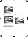
System cameras
(Video input connector 9 - 16)
10
9
VIDEO
8
7
6
5
4
3
2
AC IN
SIGNAL
GND
• • •
Combination cameras
(Video input connector 1 - 8)
29
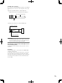
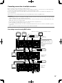
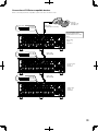
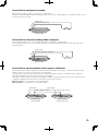
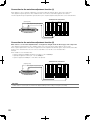
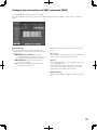
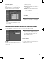
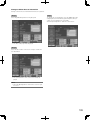
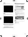
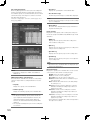
Connection of monitors
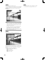
Connect monitors to the monitor output connector.
Connect a monitor to be used to display live images only to the monitor output connector 1.
Connect a monitor to be used to display not only live images but also recorded images and setup menu to the monitor output
connector 2.
The monitor can be connected using a BNC cable or a HDMI cable. (There is no difference in contents to be output to each
monitor.)
When connecting a monitor using a BNC cable
Monitor 1
* When outputting audio
Connect a powered speaker (locally procured)
Monitor 2
Powered speaker
BNC cable
(locally procured)
Audio cable
(locally procured)
Recorder
MODE
EXT STORAGE
3
2
1
DATA
RS485(CAMERA) 10/100BASE-T
123 4567 8
2
1
1
MONITOR
OUT
ALARM
15
14
13
CASCADE
2
11
10
1
CASCADE IN
OUT-CASCADE-IN
12
1
IN
2
ALARM/CONTROL
16
3
9
8
2
1
OUT MONITOR OUT(HD)
7
6
5
OUT
4
AUDIO IN
4
2 AUDIO
OUT
3
2
1
POWER
IN
ON
7
1
16
30
OFF
OUT
OUT
15
14
13
12
11
10
9
VIDEO
8
7
6
5
4
3
2
AC IN
SIGNAL
GND
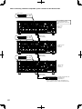
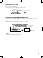
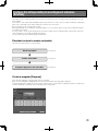
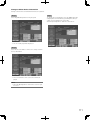
When connecting a monitor using a HDMI cable
Monitor 2
Monitor 1
HDMI cable
(locally procured)
Recorder
MODE
EXT STORAGE
3
2
1
DATA
RS485(CAMERA) 10/100BASE-T
123 4567 8
2
1
1
MONITOR
OUT
ALARM
15
14
13
CASCADE
2
11
10
1
CASCADE IN
OUT-CASCADE-IN
12
1
IN
2
ALARM/CONTROL
16
3
9
8
2
1
OUT MONITOR OUT(HD)
7
6
5
OUT
4
AUDIO IN
4
2 AUDIO
OUT
3
2
1
POWER
IN
ON
7
1
OFF
OUT
OUT
16
15
14
13
12
11
10
9
VIDEO
8
7
6
5
4
3
2
AC IN
SIGNAL
GND
Note:
• Make sure to use a HDMI cable compliant with the HDMI (high-speed) standard.
• Use a HDMI cable whose length is 10 m {32.81 ft} or less to prevent image quality deterioration and unstable performance.
• When using a HDMI cable, audio can be heard from the connected monitor. Audio can be heard only from Monitor 2.
31
Connection of a PC
Connect a PC and the recorder. Required devices and cables vary depending on how to connect them. Before starting the connection, prepare the required devices and cables.
Connect a PC and the recorder directly
Use a LAN cable to connect a PC and the recorder directly.
Recorder
MODE
EXT STORAGE
3
2
3
16
15
16
15
13
12
ALARM/CONTROL
14
12
IN
14
9
2
IN
1
OUT
2
1
OUT MONITOR OUT(HD)
8
7
6
4
3
5
AUDIO IN
2 AUDIO
OUT
1
4
3
2
IN
1
POWER
CASCADE
2
2
OUT-CASCADE-IN
13
1
RS485(CAMERA) 10/100BASE-T
CASCADE
1
CASCADE IN
OUT-CASCADE-IN
1
MONITOR
11OUT
10
ALARM
OUT
1
3
DATA
2
123 4567 8
1
ALARM/CONTROL
2
MODE
2
2
RS485(CAMERA) 10/100BASE-T
123 4567 8
1
MONITOR
OUT
EXT STORAGE
ALARM
DATA
Recorder
1
11
16
15
14
13
12
11
10
16
15
14
13
12
11
10
9
9
7
1
CASCADE IN
10
VIDEO
2
1
OUT
OUT MONITOR OUT(HD)
8
7
8
7
8
7
6
4
AUDIO IN
5
4
ON
1
OFF
OUT
2 AUDIO
OUT
3
2
6
5
4
3
2
6
5
4
3
2
AC IN
1
IN
SIGNAL
POWER
GND
1
OFF
OUT
9
VIDEO
PC
ON
7
OUT
AC IN
IP address 192.168.0.250
Subnet mask 255.255.255.0
SIGNAL
GND
LAN cable
(locally procured: 10BASE-T/100BASE-TX,
category5,
LAN
cable cross)
IP address 192.168.0.250
Subnet mask 255.255.255.0
IP address 192.168.0.x (except 0, 250 and 255)
PC
Subnet mask 255.255.255.0
IP address 192.168.0.x (except 0, 250 and 255)
Subnet mask 255.255.255.0
(locally procured: 10BASE-T/100BASE-TX,
category5, cross)
Important:
• When connecting a PC and the recorder directly (without using a hub/router), make sure to use a cross LAN cable.
• This connection is only for the setting configuration. Operation of the recorder cannot be performed by this connection.
Add the recorder to the existing network
Recorder
MODE
EXT STORAGE
3
2
3
16
15
16
15
13
12
ALARM/CONTROL
14
12
IN
14
9
2
IN
1
2
8
OUT
1
OUT MONITOR OUT(HD)
7
6
4
3
5
AUDIO IN
2 AUDIO
OUT
1
4
3
2
IN
1
POWER
CASCADE
2
2
OUT-CASCADE-IN
13
1
RS485(CAMERA) 10/100BASE-T
CASCADE
1
CASCADE IN
OUT-CASCADE-IN
1
MONITOR
11OUT
10
ALARM
OUT
1
3
DATA
2
123 4567 8
1
ALARM/CONTROL
2
MODE
2
2
RS485(CAMERA) 10/100BASE-T
123 4567 8
1
MONITOR
OUT
EXT STORAGE
ALARM
DATA
Recorder
1
11
16
15
14
13
12
11
10
16
15
14
13
12
11
10
9
9
7
1
CASCADE IN
10
8
VIDEO
2
1
OUT MONITOR OUT(HD)
7
8
7
8
7
6
OUT
4
5
AUDIO IN
4
ON
1
OFF
OUT
2 AUDIO
OUT
3
2
6
5
4
3
2
6
5
4
3
2
1
AC IN
IN
SIGNAL
POWER
GND
1
OFF
OUT
9
VIDEO
IP address 192.168.0.250
Subnet mask 255.255.255.0
192.168.0.1
IPGateway
address address:
192.168.0.250
Subnet mask 255.255.255.0
Gateway address: 192.168.0.1
PC
ON
7
OUT
AC IN
SIGNAL
GND
LAN cable
(locally procured: 10BASE-T/
100BASE-TX,
category5, straight)
LAN
cable
(locally procured: 10BASE-T/
100BASE-TX, category5, straight)
IP address 192.168.0.x
PC
(except 0, 1, 250 and 255)
mask
255.255.255.0
IPSubnet
address
192.168.0.x
Gateway
address:
(except
0, 1,
250 and192.168.0.1
255)
Subnet mask 255.255.255.0
Gateway address: 192.168.0.1
LAN*
LAN*
Hub/Router
Hub/Router
IP address: 192.168.0.1
Subnet mask: 255.255.255.0
IP address: 192.168.0.1
Subnet mask: 255.255.255.0
32
* Stands for Local Area Network
* Stands for Local Area Network
FTP server
(for image transmission)
FTP server
(for image transmission)
Connection of an extension unit
Up to 3 extension units (optional) can be connected to a single recorder. Use the dedicated cable (provided with the extension
unit) to connect between the extension unit and the recorder.
When connecting multiple extension units (WJ-HDE400) or when newly adding extension units, connect as follows. Refer also to
the operating instructions of the extension unit.
Fix the connection cable
Fix the connection cable
MODE
EXT STORAGE
3
2
1
DATA
123 4567 8
3 2 1
2
1
1
MONITOR
OUT
ALARM
Attach the cable clamp to each connection cable.
Refer to the operating instructions of the extension
unit for how to attach the cable clamp.
3
CASCADE
2
16
15
14
13
12
11
10
16
15
14
13
12
11
10
1
IN
2
OUT-CASCADE-IN
ALARM/CONTROL
1
CASCADE IN
2
1
OUT MONITOR OUT(HD)
9
8
7
9
8
7
OUT
4
AUDIO IN
2 AUDIO
OUT
6
5
4
3
2
6
5
4
3
2
1
POWER
IN
ON
7
1
OFF
OUT
OUT
VIDEO
AC IN
SIGNAL
GND
Recorder
Connection cable (provided with the extension unit)
Extension unit (Unit number: 1)
EXT IN
POWER ON
OFF
Extension unit (Unit number: 2)
EXT IN
POWER ON
OFF
Extension unit (Unit number: 3)
EXT IN
POWER ON
OFF
Important:
• Make sure to use the dedicated cable provided with the extension unit to connect.
• Fix the connection cable firmly using the cable clamp provided with the extension unit. When the cable is not connected firmly or when it is disconnected, the system may become unstable or recording may fail.
• Do not loop and bundle the cable in a circle.
• When installing the recorder or the extension unit in the rack, make a space of 1U (44 mm) above and below each of them
for ventilation.
33
Connection of a VCR
When copying images recorded on the recorder to a VCR, connect cables from a VCR to the video output connector and the
audio connector inside the SDHC/SD memory card slot cover at the front of the recorder.
VCR
AUDIO
IN
Audio cable with plugs
(locally procured)
VIDEO
IN
Video cable with plugs
(locally procured)
Recorder
ERROR
ALARM
SUSPEND
TIMER
ALARM
RESET
ALARM
STS HDD 1
HDD 2
A/F
MONITOR
SEQ
OSD
HDD 3
OPERATE
AUDIO
OUT
HDD 4
MULTI SCREEN
1
2
3
STOP
PLAY
GOTO LAST
GOTO DATE
5
6
7
8
9
0/10
11
12
14
15
16
VIDEO
OUT
SEARCH
REC REC STOP
REV
FWD
COPY
SETUP /ESC
SUB
MENU
13
PAUSE
4
SET
HOLD
Digital Disk Recorder WJ-HD616
MOUSE
Open the SDHC/SD memory card slot.
Note:
• The same images displayed on Monitor 2 will be output from the video output connector on the front of the recorder (except
when another recorder is connected in cascading connection).The audio output connectors on the front and rear are
designed to output the same audio.
• When connecting multiple recorders in cascading connection, it is impossible to output video signals of another
WJ-HD616K/WJ-HD716K from the video output connector. Connect VCRs to each recorder (WJ-HD616K/WJ-HD716K).
34
Connection of a PS·Data compatible device
The following are examples when connecting PS·Data compatible devices to the recorder. When connecting a PS·Data compatible system controller, it is possible to operate devices connected to the recorder using the system controller.
Use an RS485 cable to connect a PS·Data compatible system controller.
Important:
• Select "On" for the termination setting of the devices on both ends of the connection. Refer to the operating instructions of
each device on both ends of the connection. The termination setting of the recorder can be set using the mode switch. (☞
Page 51)
• When connecting a PS·Data compatible system controller, configure the settings on the [PS·Data setup] tab under the
"Communication" page of the setup menu according to the connection. (☞ Page 93)
• "PS·Data" is Panasonic's proprietary protocol. Contact your dealer for devices that can be connected.
• Do not assign the same unit address to two or more different PS·Data compatible devices.
When connecting a system controller to the recorder
Controller
Termination: On
Unit address: 1
Mode switch
ON
1 2 3 4 5 6 7 8
(No.7: ON)
(No.8: OFF)
RS485 cable (provided with the controller)
MODE
EXT STORAGE
3
2
1
DATA
RS485(CAMERA) 10/100BASE-T
123 4567 8
2
1
1
MONITOR
OUT
ALARM
15
14
13
CASCADE
2
11
10
1
CASCADE IN
OUT-CASCADE-IN
12
1
IN
2
ALARM/CONTROL
16
3
9
8
2
1
OUT MONITOR OUT(HD)
7
6
5
OUT
4
AUDIO IN
4
2 AUDIO
OUT
3
2
1
POWER
IN
ON
7
1
OFF
OUT
OUT
16
15
14
13
12
11
10
9
VIDEO
8
7
6
5
4
3
2
AC IN
SIGNAL
GND
Recorder
Setup menu "Communication" - [PS·Data setup]
■ Unit address (system): 1
■ Unit address (controller): 2
35
When connecting the recorder between a system controller and a system device
UNIT
POWER
ALARM
RESE T
ON
1
OFF
SUSPEND
SET UP
SE T
ESC
2
3
ALARM
ALARM
SUSPEND
4
Data Multiplex Unit WJ-MP204
RS485 cable
(WV-CA48/50)
Coaxial communication unit
Termination: On
Unit address: 2
RS485 cable
(provided with the controller)
Controller
Termination: On
Unit address: 1
Mode switch
ON
(No.7: OFF)
(No.8: OFF)
1 2 3 4 5 6 7 8
MODE
EXT STORAGE
3
2
1
DATA
RS485(CAMERA) 10/100BASE-T
123 4567 8
2
1
1
MONITOR
OUT
ALARM
15
14
13
12
11
1
IN
CASCADE
2
OUT-CASCADE-IN
ALARM/CONTROL
16
3
2
1
CASCADE IN
10
9
8
2
1
OUT MONITOR OUT(HD)
7
6
5
OUT
4
AUDIO IN
4
2 AUDIO
OUT
3
2
1
POWER
IN
ON
7
1
OFF
OUT
OUT
16
15
14
13
12
11
10
9
8
VIDEO
Recorder
7
6
5
4
3
2
AC IN
SIGNAL
GND
Setup menu "Communication" - [PS·Data setup]
■ Unit address (system): 1
■ Unit address (controller): 2
When connecting a system device to the recorder
Mode switch
1
OFF
(No.7: OFF)
(No.8: ON)
1 2 3 4 5 6 7 8
MODE
2
1
DATA
2
3
1
IN
CASCADE
2
2
OUT-CASCADE-IN
ALARM/CONTROL
RS485 cable
(WV-CA48/10K)
1
1
MONITOR
OUT
ALARM
1
CASCADE IN
2
1
OUT MONITOR OUT(HD)
16
15
14
13
12
11
10
9
8
7
16
15
14
13
12
11
10
9
8
7
OUT
4
AUDIO IN
POWER
2 AUDIO
OFF
6
5
4
3
2
6
5
4
3
2
1
1
ALARM
RESE T
2
SUSPEND
SET UP
SE T
ESC
3
ALARM
ALARM
SUSPEND
4
Data Multiplex Unit WJ-MP204
POWER
IN
ON
7
1
OFF
OUT
OUT
VIDEO
UNIT
ON
OUT
AC IN
SIGNAL
GND
SUSPEND
SET UP
SE T
ESC
3
ALARM
ALARM
SUSPEND
4
Coaxial communication unit
Termination: ON
Unit address: 3
RS485(CAMERA) 10/100BASE-T
123 4567 8
2
Data Multiplex Unit WJ-MP204
RS485 cable
(WV-CA48/50)
EXT STORAGE
3
Recorder
ALARM
RESE T
ON
ON
36
UNIT
POWER
Coaxial communication unit
Termination: OFF
Unit address: 2
Setup menu "Communication" - [PS·Data setup]
■ Unit address (system): 1
■ Unit address (controller): 1
Cascading connection of multiple recorders
Up to 5 recorders can be connected in cascading connection.
When connecting recorders in cascading connection, images displayed on Monitor 2 connected to the second and subsequent
recorders can be switched and displayed on Monitor 2 connected to the first recorder.
Use the cascade input connector, cascade output connector (monitor output connector 2 is provided as the dual purpose connector) and DATA port.
Cables are to be connected differently between when using HDMI cables and when using BNC cables.
Important:
• When multiple recorders are connecting in cascading connection, select "On" for the "Cascade" setting on the [Cascade] tab
under the "Display" page of the setup menu. (☞ Page 91)
• When connecting in cascading connection, all cables used to connect to the monitor connector shall be HDMI cables only or
BNC cables only. Do not use them together.
• Do not assign the same unit address to two or more different PS·Data compatible devices.
• Set the unit address (system) of the recorders to "1" to "5".
• In cascading connection, the time of recorders is automatically adjusted to that of the recorder whose unit address (system)
is set to "1".
• When connecting in cascading connection, all recorders shall be WJ-HD616K.
Cascading connection using BNC cables
Monitor 2
Monitor 1
* When also connecting audio cables in cascading connection
Powered
speaker
Mode switch
(No.7: OFF)
(No.8: ON)
ON
1 2 3 4 5 6 7 8
MODE
EXT STORAGE
3
2
1
DATA
2
1
16
15
14
13
11
1
4
2 AUDIO
CASCADE
2
OUT-CASCADE-IN
12
3
IN
2
ALARM/CONTROL
The "Unit address" setting on the
[PS·Data setup] tab under
"Communication" of the setup
menu
RS485(CAMERA) 10/100BASE-T
123 4567 8
1
MONITOR
OUT
ALARM
10
1
CASCADE IN
9
2
1
OUT
OUT MONITOR OUT(HD)
8
7
6
5
AUDIO IN
4
OUT
3
2
1
POWER
IN
1
14
13
12
11
10
BNC cable
(locally procured)
9
8
VIDEO
6
5
4
MODE
2
1
SIGNAL
GND
Mode switch
1 2 3 4 5 6 7 8
DATA
RS485(CAMERA) 10/100BASE-T
123 4567 8
2
1
3
1
4
2 AUDIO
IN
CASCADE
2
2
OUT-CASCADE-IN
1
CASCADE IN
2
1
OUT
OUT MONITOR OUT(HD)
16
15
14
13
12
11
10
9
8
7
16
15
14
13
12
11
10
9
8
7
AUDIO IN
OUT
6
5
4
3
2
6
5
4
3
2
1
POWER
IN
ON
7
1
VIDEO
AC IN
RS485
cable
(WV-CA
48/50)
MODE
EXT STORAGE
3
2
1
Mode switch
1 2 3 4 5 6 7 8
2
1
16
15
14
13
11
1
4
2 AUDIO
10
1
CASCADE IN
9
8
2
1
OUT MONITOR OUT(HD)
7
6
5
OUT
AUDIO IN
4
OUT
3
2
1
POWER
IN
Monitor 1
ON
7
1
OFF
OUT
OUT
16
15
14
13
12
11
Third recorder
System: 3
Controller: 3
CASCADE
OUT-CASCADE-IN
12
3
IN
2
10
9
VIDEO
8
7
(No.7: OFF)
(No.8: ON)
RS485(CAMERA) 10/100BASE-T
DATA
123 4567 8
2
ALARM/CONTROL
SIGNAL
GND
ON
1
MONITOR
OUT
ALARM
Second recorder
System: 2
Controller: 2
OFF
OUT
OUT
BNC cable
(locally procured)
(No.7: OFF)
(No.8: OFF)
ON
1
MONITOR
OUT
ALARM
ALARM/CONTROL
2
3
AC IN
EXT STORAGE
3
7
RS485
cable
(WV-CA
48/50)
BNC cable
(locally procured)
Monitor 1
OFF
OUT
15
First recorder
System: 1
Controller: 1
ON
7
OUT
16
Audio cable
(locally procured)
6
5
4
3
2
AC IN
SIGNAL
GND
Audio cable
(locally procured)
37
Cascading connection using HDMI cables
Important:
• Up to 5 recorders and a single system controller can be connected.
• Connect the recorder whose unit address (system) is even number to the cascade input 1 connector of the first recorder.
Connect the recorder whose unit address (system) is odd number to the cascade input 2 connector of the second recorder.
Connect the fourth and fifth recorders to the cascade input 1 connectors of the second and third recorders respectively.
Monitor 2
HDMI cable
(sold separately)
MODE
EXT STORAGE
3
2
1
DATA
RS485(CAMERA) 10/100BASE-T
123 4567 8
2
1
1
MONITOR
OUT
ALARM
16
15
14
13
11
1
4
2 AUDIO
10
1
CASCADE IN
9
8
2
1
OUT
OUT MONITOR OUT(HD)
7
6
AUDIO IN
5
4
OUT
3
2
1
POWER
IN
ON
7
1
OFF
OUT
OUT
16
15
14
13
12
11
First recorder
System: 1
Controller: 1
CASCADE
2
OUT-CASCADE-IN
12
3
IN
2
ALARM/CONTROL
The "Unit address" setting on the
[PS·Data setup] tab under
"Communication" of the setup
menu
10
9
VIDEO
8
7
6
5
4
2
3
AC IN
SIGNAL
GND
Third recorder
System: 3
Controller: 3
Second recorder
System: 2
Controller: 2
MODE
EXT STORAGE
3
2
1
DATA
RS485(CAMERA) 10/100BASE-T
2
3
1
ALARM
CASCADE
2
OUT-CASCADE-IN
1
CASCADE IN
2
1
16
15
14
13
12
11
10
9
8
7
16
15
14
13
12
11
10
9
8
7
4
AUDIO IN
2 AUDIO
6
5
4
3
2
6
5
4
3
2
1
POWER
IN
ON
7
1
OFF
OUT
VIDEO
2
1
AC IN
3
1
4
2 AUDIO
CASCADE
2
OUT-CASCADE-IN
ALARM/CONTROL
OUT
OUT
RS485(CAMERA) 10/100BASE-T
IN
2
OUT
OUT MONITOR OUT(HD)
DATA
123 4567 8
1
MONITOR
OUT
1
IN
2
ALARM/CONTROL
2
1
1
MONITOR
OUT
ALARM
MODE
EXT STORAGE
3
123 4567 8
1
CASCADE IN
2
1
OUT
OUT MONITOR OUT(HD)
16
15
14
13
12
11
10
9
8
7
16
15
14
13
12
11
10
9
8
7
AUDIO IN
OUT
6
5
4
3
2
6
5
4
3
2
1
ON
7
1
SIGNAL
GND
VIDEO
AC IN
MODE
EXT STORAGE
2
1
DATA
RS485(CAMERA) 10/100BASE-T
2
ALARM
13
11
1
ALARM
CASCADE
2
10
1
CASCADE IN
9
8
2
1
OUT MONITOR OUT(HD)
7
6
5
AUDIO IN
4
2 AUDIO
ALARM/CONTROL
OUT
3
2
1
POWER
IN
1
OFF
OUT
15
14
13
12
11
10
9
VIDEO
8
7
16
ON
7
6
5
4
3
DATA
RS485(CAMERA) 10/100BASE-T
123 4567 8
2
1
AC IN
SIGNAL
GND
14
13
11
10
1
CASCADE IN
OUT-CASCADE-IN
12
1
4
2 AUDIO
CASCADE
2
9
8
2
1
OUT MONITOR OUT(HD)
7
6
5
OUT
AUDIO IN
4
OUT
3
2
1
POWER
IN
ON
7
1
OFF
OUT
OUT
16
2
15
3
IN
2
OUT
4
OUT
16
1
1
MONITOR
OUT
IN
OUT-CASCADE-IN
12
2
1
3
2
ALARM/CONTROL
MODE
EXT STORAGE
3
123 4567 8
1
MONITOR
OUT
14
SIGNAL
GND
Fourth recorder
System: 4
Controller: 4
3
15
OFF
OUT
Fifth recorder
System: 5
Controller: 5
16
POWER
IN
OUT
15
14
13
12
11
10
9
VIDEO
8
7
6
5
4
3
2
AC IN
SIGNAL
GND
Note:
• Connection using the DATA port (with RS485 cables) can be made in the same manner as connection using the BNC cables
(+ page 37).
• When connecting using the HDMI cables, audio will be output together (However, audio will not be output from the audio
output connector (RCA pin jack).)
• In cascading connection, it may take time to change the monitor display.
38
Connection of PS·Data compatible devices
When connecting a PS·Data compatible system controller to the first recorder
Mode switch
ON
RS485 cable
(provided with the controller)
(No.7: OFF)
(No.8: OFF)
1 2 3 4 5 6 7 8
MODE
EXT STORAGE
3
2
1
DATA
2
1
16
15
14
3
13
CASCADE
2
OUT-CASCADE-IN
12
11
1
IN
2
ALARM/CONTROL
The "Unit address" setting on the
[PS·Data setup] tab under
"Communication" of the setup
menu
RS485(CAMERA) 10/100BASE-T
123 4567 8
1
MONITOR
OUT
ALARM
Controller
Termination: On
Unit address: 1
10
1
CASCADE IN
9
2
1
OUT MONITOR OUT(HD)
8
7
6
5
4
AUDIO IN
4
2 AUDIO
OUT
3
2
1
POWER
IN
ON
7
1
OFF
OUT
OUT
16
15
14
13
12
11
10
9
8
VIDEO
7
First recorder
System: 1
Controller: 2
OUT
6
5
4
3
2
AC IN
SIGNAL
GND
Mode switch
ON
1 2 3 4 5 6 7 8
RS485 cable
(WV-CA48/50)
(No.7: OFF)
(No.8: OFF)
MODE
EXT STORAGE
3
2
1
DATA
RS485(CAMERA) 10/100BASE-T
123 4567 8
2
1
1
MONITOR
OUT
ALARM
15
14
13
12
11
1
IN
CASCADE
2
OUT-CASCADE-IN
ALARM/CONTROL
16
3
2
10
1
CASCADE IN
9
2
1
OUT MONITOR OUT(HD)
8
7
6
5
4
AUDIO IN
4
2 AUDIO
OUT
3
2
1
POWER
IN
ON
7
1
OFF
OUT
OUT
16
15
14
13
12
11
10
9
8
VIDEO
7
6
5
4
1 2 3 4 5 6 7 8
MODE
EXT STORAGE
2
1
DATA
2
1
16
15
14
13
3
11
10
1
CASCADE IN
9
8
2
1
OUT MONITOR OUT(HD)
7
6
5
OUT
4
AUDIO IN
4
2 AUDIO
OUT
3
2
1
POWER
IN
ON
7
1
OFF
OUT
OUT
16
15
14
13
12
11
Third recorder
System: 3
Controller: 4
CASCADE
2
OUT-CASCADE-IN
12
1
IN
2
ALARM/CONTROL
SIGNAL
GND
RS485(CAMERA) 10/100BASE-T
123 4567 8
1
MONITOR
OUT
ALARM
2
RS485 cable
(WV-CA48/50)
(No.7: ON)
(No.8: OFF)
3
3
AC IN
Mode switch
ON
Second recorder
System: 2
Controller: 3
OUT
10
9
VIDEO
8
7
6
5
4
3
2
AC IN
SIGNAL
GND
39
When connecting a PS·Data compatible system controller to the third recorder
Mode switch
ON
1 2 3 4 5 6 7 8
(No.7: OFF)
(No.8: ON)
MODE
EXT STORAGE
3
2
1
DATA
123 4567 8
2
1
1
MONITOR
OUT
ALARM
15
14
3
13
CASCADE
2
OUT-CASCADE-IN
12
1
IN
2
ALARM/CONTROL
16
The "Unit address" setting on the
[PS·Data setup] tab under
"Communication" of the setup
menu
RS485(CAMERA) 10/100BASE-T
11
10
1
CASCADE IN
9
2
1
OUT MONITOR OUT(HD)
8
7
6
5
4
AUDIO IN
4
2 AUDIO
OUT
3
2
1
POWER
IN
ON
7
1
OFF
OUT
OUT
16
15
14
13
12
11
10
9
8
VIDEO
7
First recorder
System: 1
Controller: 1
OUT
6
5
4
3
2
AC IN
SIGNAL
GND
Mode switch
ON
RS485 cable
(WV-CA48/50)
(No.7: OFF)
(No.8: OFF)
1 2 3 4 5 6 7 8
MODE
EXT STORAGE
3
2
1
DATA
RS485(CAMERA) 10/100BASE-T
123 4567 8
2
1
1
MONITOR
OUT
ALARM
15
14
13
Second recorder
System: 2
Controller: 2
CASCADE
2
OUT-CASCADE-IN
12
1
IN
2
ALARM/CONTROL
16
3
11
10
1
CASCADE IN
9
2
1
OUT
OUT MONITOR OUT(HD)
8
7
6
5
4
AUDIO IN
4
2 AUDIO
OUT
3
2
1
POWER
IN
ON
7
1
OFF
OUT
OUT
16
15
14
13
12
11
10
9
8
VIDEO
7
6
5
1 2 3 4 5 6 7 8
MODE
EXT STORAGE
2
1
DATA
2
1
16
15
14
13
3
11
10
1
CASCADE IN
9
8
2
1
OUT MONITOR OUT(HD)
7
6
5
OUT
4
AUDIO IN
4
2 AUDIO
OUT
3
2
1
POWER
IN
ON
7
1
OFF
OUT
OUT
16
15
14
13
12
11
Third recorder
System: 3
Controller: 3
CASCADE
2
OUT-CASCADE-IN
12
1
IN
2
ALARM/CONTROL
SIGNAL
GND
RS485(CAMERA) 10/100BASE-T
123 4567 8
1
MONITOR
OUT
ALARM
2
RS485 cable
(WV-CA48/50)
(No.7: OFF)
(No.8: OFF)
3
3
AC IN
Mode switch
ON
4
10
9
VIDEO
8
7
6
5
4
3
2
AC IN
SIGNAL
GND
RS485 cable
(WV-CA48/50)
POWER
UNIT
ALARM
RESE T
ON
OFF
1
2
SUSPEND
SET UP
SE T
ESC
3
ALARM
ALARM
SUSPEND
4
Data Multiplex Unit WJ-MP204
Coaxial communication unit
Termination: On
Unit address: 6
* Set "6" or greater numbers for the unit addresses of
system devices such as a coaxial communication unit.
40
When connecting PS·Data compatible system controllers to both the first and the third recorders
Controller
Termination: On
Unit address: 1
RS485 cable
(provided with the controller)
Mode switch
ON
(No.7: OFF)
(No.8: OFF)
1 2 3 4 5 6 7 8
MODE
EXT STORAGE
3
2
1
DATA
RS485(CAMERA) 10/100BASE-T
123 4567 8
2
1
1
MONITOR
OUT
ALARM
16
15
14
3
13
11
10
1
CASCADE IN
9
2
1
OUT
OUT MONITOR OUT(HD)
8
7
6
5
4
AUDIO IN
4
2 AUDIO
OUT
3
2
1
POWER
IN
ON
7
1
OFF
OUT
OUT
16
15
14
13
12
11
10
9
8
VIDEO
7
6
5
MODE
EXT STORAGE
3
2
1
DATA
2
SIGNAL
GND
1
3
1
IN
CASCADE
2
2
OUT-CASCADE-IN
ALARM/CONTROL
2
RS485(CAMERA) 10/100BASE-T
123 4567 8
1
MONITOR
OUT
ALARM
3
RS485 cable
(WV-CA48/50)
(No.7: OFF)
(No.8: OFF)
1 2 3 4 5 6 7 8
4
AC IN
Mode switch
ON
First recorder
System: 1
Controller: 2
CASCADE
2
OUT-CASCADE-IN
12
1
IN
2
ALARM/CONTROL
The "Unit address" setting on the
[PS·Data setup] tab under
"Communication" of the setup
menu
1
CASCADE IN
2
1
OUT MONITOR OUT(HD)
16
15
14
13
12
11
10
9
8
7
16
15
14
13
12
11
10
9
8
7
4
AUDIO IN
2 AUDIO
OUT
6
5
4
3
2
6
5
4
3
2
1
POWER
IN
ON
7
1
OFF
OUT
OUT
VIDEO
Second recorder
System: 2
Controller: 3
OUT
AC IN
SIGNAL
GND
Mode switch
ON
RS485 cable
(WV-CA48/50)
(No.7: OFF)
(No.8: OFF)
1 2 3 4 5 6 7 8
MODE
EXT STORAGE
3
2
1
DATA
RS485(CAMERA) 10/100BASE-T
123 4567 8
2
1
1
MONITOR
OUT
ALARM
15
14
13
12
11
1
IN
10
1
CASCADE IN
9
8
2
1
OUT MONITOR OUT(HD)
7
6
5
OUT
4
AUDIO IN
4
2 AUDIO
OUT
3
2
1
POWER
IN
ON
7
1
OFF
OUT
OUT
16
15
14
13
12
11
Third recorder
System: 3
Controller: 4
CASCADE
2
OUT-CASCADE-IN
ALARM/CONTROL
16
3
2
10
9
VIDEO
8
7
6
5
4
3
2
AC IN
SIGNAL
GND
RS485 cable
(WV-CA48/50)
POWER
UNIT
ALARM
RESE T
ON
OFF
1
2
SUSPEND
SET UP
SE T
ESC
3
ALARM
ALARM
SUSPEND
4
Data Multiplex Unit WJ-MP204
Coaxial communication unit
Termination: On
Unit address: 6
* Set "6" or greater numbers for the unit addresses of
system devices such as a coaxial communication unit.
41
Connection of RS485 cameras
The following are examples when connecting RS485 cameras to the recorder.
Up to 8 RS485 cameras can be connected to a single RS485 port.
Important:
• Select "On" for the termination setting of the devices on both ends of the connection. The termination setting of the recorder
can be set using the mode switch. (☞ Page 51)
• When connecting RS485 cameras, configure the settings on the [RS485 setup] tab under the "Communication" page of the
setup menu together with the RS485 settings of each camera. (☞ Page 94)
• The maximum RS485 cable length for this connection is 1 200 m {3 937 ft}.
1-on-1 connection
Connect a single RS485 camera to the RS485 port.
Example: When connecting RS485 cameras to the video input connector 9 and 13
Mode switch
ON
(No.1 and No.4: ON)
1 2 3 4 5 6 78
Recorder
MODE
EXT STORAGE
3
2
1
DATA
RS485(CAMERA) 10/100BASE-T
123 4567 8
2
1
1
MONITOR
OUT
ALARM
16
15
14
13
12
11
1
4
2 AUDIO
CASCADE
2
OUT-CASCADE-IN
ALARM/CONTROL
3
IN
2
10
1
CASCADE IN
9
8
2
1
OUT MONITOR OUT(HD)
7
6
5
OUT
AUDIO IN
4
OUT
3
2
1
POWER
IN
ON
7
1
OFF
OUT
OUT
16
15
14
13
12
11
10
9
VIDEO
8
7
6
5
4
3
2
AC IN
SIGNAL
GND
RS485 cable (WV-CA48/50)
RS485 camera
connection
destination
RS485 (1)
Switch to
be set
No.2 and
No.3
4-wire connection
ON
ON
1 2 3 4 5 6 78
(No.2 and No.3: OFF)
RS485 (2)
No.5 and
No.6
ON
1 2 3 4 5 6 78
Unit number 9
Termination: On
Combination camera
42
1 2 3 4 5 6 78
(No.2 and No.3: ON)
ON
(No.5 and No.6: OFF)
Unit number 13
Termination: On
2-wire connection
1 2 3 4 5 6 78
(No.5 and No.6: ON)
Daisy chain connection
Connect multiple RS485 cameras to the RS485 port.
Example: When connecting camera 1-4 (coaxial communication) to the video input connector 1-4 and camera 9-12 (RS485) to
the RS485 port 1
RS485 camera
connection
destination
RS485 (1)
Switch to
be set
No.2 and
No.3
4-wire connection
2-wire connection
ON
ON
1 2 3 4 5 6 78
1 2 3 4 5 6 78
(No.2 and No.3: OFF)
RS485 (2)
No.5 and
No.6
ON
(No.2 and No.3: ON)
ON
1 2 3 4 5 6 78
Mode switch
1 2 3 4 5 6 78
(No.5 and No.6: OFF)
ON
(No.5 and No.6: ON)
1 2 3 4 5 67 8
Recorder
MODE
EXT STORAGE
3
2
1
DATA
RS485(CAMERA) 10/100BASE-T
123 4567 8
2
1
1
MONITOR
OUT
ALARM
15
14
13
12
11
1
IN
CASCADE
2
OUT-CASCADE-IN
ALARM/CONTROL
16
RS485 cable
(WV-CA48/50)
3
2
10
1
CASCADE IN
9
8
2
1
OUT MONITOR OUT(HD)
7
6
5
OUT
4
AUDIO IN
4
2 AUDIO
OUT
3
2
1
POWER
IN
ON
7
1
OUT
16
15
14
Unit number 11
Termination: Off
Unit number 12
Termination: On
OFF
OUT
13
12
11
10
Unit number 9
Termination: Off
Unit number 10
Termination: Off
9
VIDEO
8
7
6
5
4
3
2
AC IN
SIGNAL
GND
Combination camera
(Supporting coaxial communication)
Combination camera (RS485)
43
About the connectors
How to use the terminals of the ALARM/CONTROL connector
These terminals are used for emergency recording, auto time adjustment and when installing a buzzer, a lamp or a similar alarm
device.
The connector to be used should be compatible with the pin array.
13
1
Pin array
The pin array is different from other digital disk recorders. Make sure
that the connection is correct referring to the following.
ALARM/CONTROL
25
Pin No.
44
Signal
1
Alarm output 8
2
Alarm output 9
3
Alarm output 10
4
Alarm output 11
5
Alarm output 12
6
Alarm output 13
7
Alarm output 14
8
Alarm output 15
9
Alarm output 16
10
N/A
11
Operation
14
Remarks
Alarm signal will be supplied at an event occurrence
Open collector output
24 V DC max., –100 mA
Alarm reset input
Canceling the alarm display
12
Emergency recording input
Starting emergency recording signal input
Non-voltage make contact
input/5 V pull-up
13
Signal ground
14
Signal ground
15
Available disk space warning
output
Signal output for available (remaining) disk space
warning of the normal recording area/event
recording area/copy area
16
HDD error output
Signal output upon detection of an HDD error
17
Camera error output
Signal output upon detection of a camera error
18
Error output
Signal output upon detection of a recorder error
19
Outage processing end
output
Signal output upon completion of outage processing
High (+12 V) 12 mA
20
Time adjustment I/O
According to the signal input, the time of this
recorder will be generated as the signal output,
and then the time of all other recorders is adjusted to the time of this recorder.
30 kΩ, 5 V pull-up, Output current – 100 mA/Non-voltage make
contact input
21
Sequence switchover I/O
According to the signal input, the sequence
operation will be switched and the signal output
will be generated upon the sequence switchover.
22
Alarm suspension input
The state of the alarm suspension is assigned
according to the signal input.
23
Outage detection input
Start the outage processing according to the signal input.
24
External recording mode
switching input
Changeover to the external recording mode
25
+5 V output
+5 V output
Open collector output/
24 V DC max., – 100 mA
Non-voltage make contact
input/5 V pull-up, –100 mA
200 mA max.
Connection for emergency recording
When the external switch is turned on, emergency recording will start.
Emergency recording will differently be performed depending on the settings on the [Emergency rec.] tab under the "Basic" page
of the setup menu. (☞ Page 70)
(Signal ground)
(Emergency recording input)
13
12
External switch
ALARM/CONTROL
Connection for external recording mode changeover
When the external switch is set to "On", recording will start after changing the recording program.
The recording program can be set on "Time table setup(Ext.)" on the [Time table] tab under the "Schedule" page of the setup
menu (☞ Page 81).
(Signal ground)
(External recording mode changeover)
13
24
External switch
ALARM/CONTROL
Connection for synchronization of the sequence switchover
Camera channel of the sequence display will be switched upon the signal input to the sequence switchover input. When using
multiple recorders, it is possible to synchronize the switchover timing.
The setting for the sequence switchover timing can be configured on "Sequence timing" on the [Monitor 1] tab (or "Monitor 2"
tab) under the "Display" page of the setup menu (☞ Pages 86 and 88).
When synchronizing the sequence switchover timing between multiple recorders, the setting for the sequence switchover timing
is differently configured between the master recorder and the slave recorder as follows.
Master recorder: Set to "Int" (functions as the output terminal)
Slave recorder: Set to "Ext" (functions as the input terminal)
(Signal ground)
(Signal ground)
(Sequence switchover output)
13
21
(Sequence switchover input)
13
21
ALARM/CONTROL
ALARM/CONTROL
WJ-HD616K (First)
WJ-HD616K (Second)
45
Connection for the auto time adjustment function (1)
When "Master" is set for "Auto time adjustment" on the [Time & date] tab under the "Basic" page of the setup menu
"Time adjustment signal output" becomes available and the clock of this recorder will be applied to other devices.
The time adjustment signal output will be generated from pin no. 20 (time adjustment I/O) at the time set for "Activation time"
Terminal of the other device
(Time adjustment signal output)
13
20
Output for the
indicators on
the front panel
Signal ground
Sensor signal input
Alarm input
Alarm reset input
Series recording output
Time adjustment signal input
Signal ground
Alarm output
Alarm reset output
Alarm recording
During recording
Disk
Buzzer output
System error output
Thermal error output
Time adjustment signal output
Series recording output
(Signal ground)
ALARM/CONTROL
Connection for the auto time adjustment function (2)
When "Slave" is set for "Auto adjustment time" on the [Time & date] tab under the "Basic"page of the setup menu
"Time adjustment signal input" becomes available and the clock of the other device will be applied to this recorder.
When a signal output from the other device is supplied to the time adjustment I/O terminals (pin no. 20) 15 minutes before/after
the time set for "Activation time", the clock of the recorder will be set to the time set for "Activation time".
Example:
When "15:00" is set for "Activation time"
• Signal is supplied at 2:50:00 (hour:minute:second) pm → Set at 3:00:00 pm
• Signal input supplied at 3:14:45 pm → Set at 3:00:00 pm
• Signal is supplied at 3:20:00 pm → Time will not be adjusted.
Terminal of the other device
(Time adjustment signal output)
13
20
Output for the
indicators on
the front panel
Signal ground
Sensor signal input
Alarm input
Alarm reset input
Series recording output
Time adjustment signal input
Signal ground
Alarm output
Alarm reset output
Alarm recording
During recording
Disk
Buzzer output
System error output
Thermal error output
Time adjustment signal output
Series recording output
(Signal ground)
ALARM/CONTROL
Important:
• When "Slave" is selected, the clock will not be adjusted during event recording or emergency recording.
46
Connection of the control output
When an alarm device such as a buzzer or a lamp is connected, the signal output from pin nos.15 - 18 can be used to notify the
status by sounding a buzzer or lighting a lamp.
The following example is of a connection with the HDD error output (pin no. 16).
(Signal ground)
(HDD error output)
13
16
Alarming device
Relays, etc.*
* Attached when necessary
ALARM/CONTROL
Connection with the Uninterruptible Power System (UPS)
This is an example of a connection with the uninterruptible power system (UPS) to be installed to protect from a power outage.
When a signal is supplied to the outage detection input terminals from the uninterruptible power system (UPS), internal processing (stops recording safely) will start to shut off the power supply for the recorder.
After completing the internal processing, a signal will be supplied from the outage processing end output terminal to the uninterruptible power system (UPS). Then, the power supply to the recorder can be suspended.
(Signal ground)
(Signal ground)
(Detection)
(Outage detection input)
(Outage processing end output)
Recorder
13
23
(Shutdown)
* Refer to the operating
instructions of the UPS
in use for how to
connect the UPS.
19
Power cord
Uninterruptible
Power System
(UPS)
ALARM/CONTROL
To electric outlet
Important:
• Be sure to use an UPS that provides a sine wave output.
Do not use an UPS that provides a square wave. It may damage the recorder.
47
How to use the terminals of the ALARM connector
These terminals are used to connect the alarm devices, such as sensors, door switches, etc.
The connector to be used should be compatible with the pin array.
13
1
Pin array
The pin array is different from other digital disk recorders. Make sure
that the connection is correct referring to the following.
Alarm
25
Pin No.
1
Alarm input 1
2
Alarm input 2
3
Alarm input 3
4
Alarm input 4
5
Alarm input 5
6
Alarm input 6
7
Alarm input 7
8
Alarm input 8
9
Alarm output 1
10
Alarm output 2
11
Alarm output 3
12
Alarm output 4
13
Signal ground
14
Signal ground
15
Alarm input 9
16
Alarm input 10
17
Alarm input 11
18
Alarm input 12
19
Alarm input 13
20
Alarm input 14
21
Alarm input 15
22
Alarm input 16
23
Alarm output 5
24
Alarm output 6
25
Alarm output 7
48
Signal
Operation
14
Remarks
Event actions will be performed according to the
settings.
Non-voltage make contact
input/5 V pull-up/–100 mA
Alarm signal will be supplied at an event occurrence
Open collector output
24 V DC max., –100 mA
Event actions will be performed according to the
settings.
Non-voltage make contact
input/5 V pull-up/–100 mA
Alarm signal will be supplied at an event occurrence
Open collector output
24 V DC max., –100 mA
Alarm connection
When a signal is supplied to the alarm input terminals 1 - 16 (pin nos. 1 - 8, 15 - 22 of the ALARM connector), recording and displaying of images from the cameras will be performed according to the settings.
When an alarm device such as a buzzer, a lamp, etc., is installed outside, connect them to the alarm output terminals (pin nos. 9
- 12, 23 - 25 of the ALARM connector or pin nos. 1 - 9 of the ALARM/CONTROL connector).
Sensor
(Alarm input 16)
(Signal ground)
(Alarm input 1)
Door security
switch
22
14
1
Alarm
(Signal ground)
13
Alarming device
Relays, etc.*
* Attached when necessary
9
(Alarm output16)
ALARM/CONTROL
49
Time and polarities of the ALARM/CONTROL terminal and the ALARM
terminal
Terminal
Active time
Remarks
100 ms or more
When N.O.: L active
When N.C.: H active
Alarm output
The set time on the setup menu
L active
Alarm reset input
100 ms or more
L active
Emergency recording input
100 ms or more
L active
Available disk space warning
output
Duration set for "Buzzer"* starting from the time of the
error occurrence
L active
HDD error output
Duration set for "Buzzer"* starting from the time of the
error occurrence
L active
Camera error output
Duration set for "Buzzer"* starting from the time of the
error occurrence, or until the camera is reset (from the
time of the error occurrence).
L active
Error output
Duration set for "Buzzer"* starting from the time of the
error occurrence
L active
Time adjustment I/O
Input: 100 ms or more, Output: 1 s
Input/Output: L active
Alarm suspension input
100 ms or more
L active, judged by level
External recording mode
changeover
100 ms or more
L active, judged by level
Sequence switchover I/O
100 ms or more
L active
Outage detection input
5 s or more
L active
Outage processing end output
10 s or more
H active
Alarm input
* "Buzzer" can be set on the "Basic" page of the setup menu. (☞ Page 65)
Note:
• During "L active (Low active)", the logic will be implemented when the voltage level of signal is low.
• During "H active (High active)", the logic will be implemented when the voltage level of signal is high.
50
Mode switch
Communication between the recorder and a system device using PS·Data can be performed by RS 485 interface. Devices on
both ends of the RS485 connection are necessary to be terminated.
The mode switch setting differs depending on whether to use the recorder as a receiver or a system controller.
When connecting RS485 cameras to the recorder, devices on both ends of the connection are necessary to be terminated.
• When the recorder is on the end of the connection with a system controller
PS·Data termination switch 1: On
• When the recorder is on the end of the connection with a
device controller
PS·Data termination switch 2: On
• When connecting RS485 cameras
Set the termination switch of the RS485 port to which the
RS485 camera is connected
Connect to the RS485 port 1: Set the termination switch of
the RS485 port (1) to "On".
Connect to the RS485 port 2: Set the termination switch of
the RS485 port (2) to "On".
• When connecting in 2-wire connection
Connect to the RS485 port 1: Set no. 2 and no. 3 to "On".
Connect to the RS485 port 2: Set no. 5 and no. 6 to "On".
• When connecting in 4-wire connection
Connect to the RS485 port 1: Set no. 2 and no. 3 to "Off".
Connect to the RS485 port 2: Set no. 5 and no. 6 to "Off".
RS485 (1) Termination switch
RS485 (1) 2-wire/4-wire
connection switch
RS485 (2) Termination switch
RS485 (2) 2-wire/4-wire
connection switch
PS·Data termination switch 1
PS·Data termination switch 2
ON
1 2 3 4 5 6 7 8
RS485 port
Inside block diagram
TA
TB
DATA
GND RB RA
IN
TA TB GND
RA
RB
OUT
51
Install/remove HDD units
Install the HDD units
Install the HDD units by referring the disk slot number.
Detach the front cover in advance. (☞ Page 21)
Step 1
Remove the HDD unit brace.
Removal knob
Press
of the(3)
HDD
unit
the lever down and push it until the removal knob
clicks.
Lever
(2)
Hook
Rim
HDD unit brace
Step 2
Install the HDD units by referring the disk slot number.
(1) Lift the lever on the HDD unit while holding down the
removal knob, and then insert the HDD unit all the way
into the HDD slot.
Removal
knob of the
HDD unit
Lever
(2) Pinch the rim on the HDD slot with the hook on the HDD
unit securely.
52
(3)
Important:
• Keep the removed HDD unit brace securely. When transporting the recorder, it is necessary to attach it.
• Hard disk drives are precise devices. Handle with care
while keeping the following in mind.
• Do not subject the hard disk drive to any vibration or
impact.
Before touching the hard disk drive, eliminate static electricity by touching a steel locker, etc. When holding the
hard disk drive, hold the both sides of the hard disk
drive.
• Do not touch the circuit board or the connectors to prevent the hard disk drive from damaging by static electricity.
• Contact your dealer for hard disk drives that works on
the recorder. Please be forewarned that operation with
any hard disk drive other than the specified models is
not guaranteed under any circumstances.
• When using multiple hard disk drives, use the same
model.
If different models are used together, even when the
capacities of them are the same, the available capacity
may be a few percent smaller.
• Install the hard disk drives one by one in order starting
from HDD1.(The leftmost slot of the HDD slots is HDD1
and the rightmost one is HDD4.)
• Once the operation has started in the RAID 5 or RAID 6
mode, do not change the positions of the HDD units. If
they are changed, it may become impossible to read
recorded data.
Note:
• Hard disk drives are locally procured. Contact your dealer for purchasing, installing, and replacing the hard disk
drives.
• Refer to the operating instructions of the extension unit
for how to install the HDD units on the extension unit.
Remove the HDD unit
Step 1
Remove the HDD unit brace. (☞ Page 52)
Before removing an HDD unit, turn off the power of the
recorder (☞ page 55) or the power of the HDD unit to be
removed (☞ page 133).
Install a hard disk drive into an
HDD canister
To install a hard disk drive in the recorder, it is necessary to
assemble an HDD unit (encase the hard disk drive in the
HDD canister).
Step 1
Fix both sides of the hard disk drive with the dedicated HDD
canister using the 4 provided screws for HDD canister installation.
Tightening torque for the screws: 0.49 N·m {0.36 lbf·ft} (use
a low-torque powered screwdriver or a torque screwdriver)
HDD fixing screws for the HDD canister
Step 2
(1) Pull the lever while holding down the removal knob on
the HDD unit.
HDD fixing screws for the HDD canister
Removal
knob of the
HDD unit
Step 2
Lever
Removal
(2)
Pull the HDD unit out from the HDD slot while holding
knob of the
theunit
lever. Pull the HDD unit out carefully so as not to
HDD
drop it and handle
Leverit gently so as not to give it a shock or
vibration.
Fix the bottom of the hard disk drive with the HDD canister
using the 2 provided screws for HDD canister installation.
Tightening torque for the screws: 0.49 N·m {0.36 lbf·ft} (use
a low-torque powered screwdriver or a torque screwdriver)
HDD fixing screws for the HDD canister
Lever
Lever
Important:
• When installing hard disk drives, use a low-torque powered screwdriver or a torque screwdriver to tighten
screws with the specified torque.
Note:
• Hard disk drives are locally procured. Contact your dealer for purchasing, installing, and replacing the hard disk
drives.
53
Determine the operational mode of the hard disk drives
It is possible to operate the recorder with the RAID function that is known as the HDD fault-tolerance system by installing an
optional RAID board. Refer to the operating instructions of the RAID board for how to install the RAID board.
The following operational modes are provided to the RAID function of the recorder.
RAID 5 mode: it is possible to recover recorded images even when a single hard disk drive becomes faulty.
RAID 6 mode: it is possible to recover recorded images even when 2 hard disk drives become faulty.
Proceed as follows to switch the operational mode of the RAID function.
Step 1
Step 5
Turn off the power of the recorder. (☞ Page 55)
Step 2
Detach the front cover. (☞ Page 21)
Press the power switch while holding down the [USE] button.
→ When the recorder is booted, the setting will be applied,
and the hard disk drives will be automatically formatted.
Hold down the [USE] button until the buzzer start sounding.
Step 3
Determine the operational mode using the [RAID] switch.
S: Single mode (default)
R5: RAID 5 mode
R6: RAID 6 mode
ERROR
ALARM
SUSPEND
TIMER
ALARM
RESET
ALARM
STS
HDD 1 A/F
HDD 2
USE
RAID
•S
• R5
• R6
RAID switch
HDD 3
OPERATE
AUDIO
OUT
ESC
SET
HDD 4
VIDEO
OUT
Important:
• Do not change the operational mode of the hard disk
drives after running the system. Once the operation has
started in the RAID 5 or RAID 6 mode, do not change
the positions of the HDD units. If it is changed, it may
become impossible to read recorded data correctly.
Note:
• The RAID 5 mode is operable only when 3 or more hard
disk drives are installed in the recorder. The RAID 6
mode is operable only when 4 or more hard disk drives
are installed in the recorder.
• When using an extension unit, change the operational
mode after connecting it to the recorder.
Step 6
Step 4
When an extension unit is connected, boot the extension
unit first before booting the recorder.
54
After the recorder is booted, attach the front cover to the
recorder. (+ Page 21)
Startup
Turn on the power
Turn on the power of the recorder.
Step 1
Connect the power plug to an electric outlet.
Step 2
Press the power switch at the rear of the recorder to turn on
the power.
→ The operate indicator will light and the system check
(checking the recorder and the hard disk drives) will
start.
The startup screen will be displayed on Monitor 2 during
the system check process.
When the system check is complete, live images from
the camera will be displayed (☞ Operating Instructions
(PDF)).
Note:
• When the login window is displayed during operation
after startup, enter the user name and password.
Refer to Operating Instructions (PDF) for how to operate.
Important:
• Do not turn off the power during the startup process.
• When using the extension units (WJ-HDE400), turn on
the power of the recorder after turning on the power of
all the extension units.
Turn off the power
Turn off the power of the recorder. To turn off the power of the recorder during recording or playback, proceed as follows.
During recording
Step 1
Select "Off" for "Recording" on the [Recording] tab under the
"Basic" page of the setup menu to stop all recordings.
(☞ Page 68)
Step 2
Turn off the power of the recorder after confirming that all the
HDD access indicators (A/F (HDD access/failure)) are off.
→ The operate indicator will go off.
Note:
• Start recordings after turning on the power of the server.
Currently recorded images are being played
Step 1
Press this button to stop playback.
(☞ Operating Instructions (PDF))
Step 2
Turn off the power of the recorder after confirming that all the
HDD access indicators (A/F (HDD access/failure)) are off.
→ The operate indicator will go off.
Important:
• Remove the plug from the outlet if not operating the
recorder for a length of time.
• Turn on the power (approx. once a week), and perform
recording/playback to prevent interferences with functions.
• When using the optional extension units (WJ-HDE400),
turn off the power of all the extension units after turning
off the power of the recorder.
55
Configure the minimum settings required to use the recorder
Configure the minimum settings required to use the recorder such as the time and date setting, the language setting, the settings
relating to recording and the schedule settings on the "Quick" page of the setup menu.
Refer to page 59 for further information about the basic operations of the setup menu.
Step 1
Hold down the [SETUP/ESC] button for 2 seconds or more.
→ The setup menu ("Setup" tab under the "Quick" page)
will be displayed on Monitor 2.
Note:
• When the quick setup page is not displayed, select the
[Quick] button.
Step 2
Configure each setting item. Refer to page 63 for descriptions about each setting item.
56
Setup menu
Configuration of each setting item in the setup menu should be completed in advance to use this recorder.
The operations in the setup menu are performed with either of the following:
• Displaying the setup menu on Monitor 2 by using buttons on the front cover or a mouse connected to the recorder
• Displaying the setup menu on the web browser of a PC monitor (when controlling the recorder via a network
When operating the recorder using the web browser, the setup menu will be displayed by clicking the [Setup] button on the operation window.
The operation window displayed on the web browser is same as that displayed on Monitor 2.
(However, it is impossible to configure the settings of the "SD5Link" page from the web browser.)
The following are the descriptions of how to operate the setup menu by using the buttons on the front cover.
When operating the recorder using the web browser, click the buttons or tabs related to the desired operation on the PC monitor.
After completing the settings on each page, click the [Set] button below the setting items.
57
About Setup menu
q
w
e
r
t
y
u
i
!3
o
!0
!1
!2
q [Quick] button
Select this button to display the "Quick" page (☞ page
63). The minimum settings required to operate the
recorder such as the time & date, language, recording
schedule, etc. can be configured on the "Quick" page.
w [Basic] button
Select this button to display the "Basic" page (☞ page
65). The basic settings relating to the system such as
time & date, recording actions and audio and the settings relating to the emergency recording can be configured on the "Basic setup" page.
e [Event] button
Select this button to display the "Event" page (☞ page
71). The settings relating to the event actions to be taken
at an event occurrence, the VMD areas and the alarm
notification can be configured on the "Event" page.
r [Schedule] button
Select this button to display the "Schedule" page
(☞ page 79). The settings for the recording schedules
and event actions are performed by designating a day of
the week and time.
t [Display] button
Select this button to display the "Display" page
(☞ page 83). The settings relating to the display of
Monitor 1, Monitor 2 and a PC monitor and the setting
relating to the camera channels to be displayed on the
multi screen, and the settings relating to the sequential
display can be configured on the "Display" page.
58
y [Communication] button
Select this button to display the "Communication" page
(☞ page 92). The settings relating to the communication
with other devices such as the communication method
to control cameras, the PS·Data and the RS485 communication, etc. can be configured on the
"Communication" page.
u [Server] button
Select this button to display the "Server" page
(☞ page 95). The settings relating to the network time &
date, FTP server and notification by e-mail can be configured on the "Serve" page.
i [Network] button
Select this button to display the "Network" page
(☞ page 99). The network settings of the recorder and
the settings relating to DNS, DDNS, SNMP, FTP,
Panasonic alarm protocol and live image transmission
can be configured on the "Network" page.
o [User mng.] button
Select this button to display the "User mng." (User management) page (☞ page 106). The settings relating to
the authentication such as users' and PCs' restrictions
for accessing the recorder and the operation levels can
be configured on the "User mng." page.
!0 [SD5Link] button
* It is impossible to configure the settings from the
web browser.
Select this button to display the "SD5Link" page
(☞ page 113). The settings relating to the VMD areas,
detection mode and detection sensitivity level, etc. for
SD5 cameras can be configured on the "SD5Link" page.
!1 [Maintenance] button
Select this button to display the "Maintenance" page (☞
page 119).
Check and setup of the hard disk drive information of
the recorder, management of the setup data and check
of log information can be carried out on the
"Maintenance" page. Formatting SD memory cards and
displaying the disk configuration page can also be carried out on the "Maintenance" page.
!2 [Exit] button
Exits the setup menu when finishing the operation of
setup menu. The settings will be applied.
!33 Setup page
Displays each setup page. There are tabs for some
setup pages.
How to operate the setup menu
The settings required to operate the recorder are configured on the setup menu in advance.
The setup menu is displayed on Monitor 2.
Note:
• The setup menu can also be displayed by holding down the [SETUP/ESC] button (for more than 2 seconds) on the front
panel of the recorder.
• At the startup of the setup menu for the first time, "Quick" page will be displayed as the top page of the setup menu.
After operating the recorder on the "Quick" page or each setup page, the "Basic" page (☞ page 65) will be displayed as the
top page of the setup menu from the next time.
Operation using buttons on the front cover
Step 1
SUB
MENU
Operation using a mouse connected to the recorder
Step 1
Display the setup menu.
Display the sub menu by pressing the [SUB
MENU] button, move the cursor to "Setup
Menu", and press the [SET] button.
Display the setup menu.
Click "S.Menu" on the status bar below the screen, and click
"Setup Menu" on the "Sub Menu" window.
➜
→ The setup menu window opens.
Note:
• While live images are being displayed, hold down the
[SETUP/ESC] button for more than 2 seconds.
59
Operation using buttons on the front cover
Step 2
Operation using a mouse connected to the recorder
Step 2
Select the desired setup menu.
Press the [SET] button after moving the cursor to the desired setup menu using the
arrows button (C D A B).
Select the desired setup menu.
Put the mouse cursor on the desired setup menu, and click
the mouse button.
SET
Step 3
Step 3
Select the desired tab.
Press the [SET] button after moving the cursor to the desired tab using the arrows button
(C D A B).
Select the desired tab.
Put the mouse cursor on the desired tab, and click the
mouse button.
SET
→ T
he setup menu page of the selected tab
will be displayed.
60
→ The setup menu page of the selected tab will be displayed.
Operation using buttons on the front cover
Step 4
Operation using a mouse connected to the recorder
Step 4
Configure each setting item.
Selection of setting item
Press the [SET] button after moving the cursor to the desired item using the arrows button (C D A B).
Display of advanced setup pop-up page
Move the cursor to "Setup" of the setting
item, and press the [SET] button.
Configure each setting item.
To display the advanced settings page of the selected setting item, select "Setup" from the right-click pop-up menu.
Change of pages
Click [D Pervious page] or [C Next page].
Change of settings (or setting values)
Change the setting (or setting value) by clicking C or D.
Click the desired setting (or setting value) by clicking C
Change of pages
Press the [SET] button after moving the cursor to the desired setup menu using the
arrows button (C D A B).
Change of settings (or setting values)
Either of the following is available.
• Rotate the JogDial (inside).
• Press the [SET] button after moving the
cursor to the setting item. Available values will
be displayed. Then, press the [SET] button
after moving the cursor to the desired setting
(or setting value).
1
to
0/10
SET ESC
Enter a value
It is possible to enter a value by pressing the
desired camera selection buttons ([1] to
[1/10]).
The available setting values are as follows.
Camera preset positions, HTTP port number,
FTP port number, IP address, subnet mask,
default gateway, primary server address, secondary server address
Return to tab selection
Press the [SETUP/ESC] button to return to
Step 3 to select a tab.
61
Step 5
SET ESC
Holding down
(for more than
2 seconds)
Step 5
Apply the settings to the recorder, and
exit the setup menu.
Hold down the [SETUP/ESC] button for 2
seconds or more.
→T
he monitor display will return to live images.
Apply the settings to the recorder, and exit the setup
menu.
Click the [Exit] button.
or
SET
Press the [SET] button after moving the cursor to the [Exit] button using the arrows button (C D A B).
→T
he confirmation window will be displayed
to save the settings.
→ The confirmation window will be displayed to save the
settings.
Important:
• To exit the setup menu without saving the settings, select the [No] button on the confirmation window.
• If the settings are applied, all login users will be forcibly logged out.
About the operation of on-screen keyboard (for character entry)
Setting items can be entered using the on-screen keyboard (for character entry).Press the [SET] button after moving the cursor to
the entry field. On-screen keyboard (for character entry) will be displayed, and it is possible to enter the characters.
When using a mouse, it is possible to set by clicking the
icon.
62
Configure the minimum settings required to operate the recorder [Quick]
The minimum settings required to operate the recorder such as the language, time & date, network and schedule, etc. can be
configured on the "Quick" page. The "Quick" page has only the [Setup] tab.
First, configure the minimum settings on the "Quick" page, and to configure more advanced settings, go to each setup menu.
[Language]
Select the desired language of the setup menu.
Japanese/English/Français/Español/Deutsch/Italiano/
Russian
Default: English
[Time & date]
Set the current time & date.
Year, month, day, time and minute are set.
When using a mouse, it is possible to set by clicking the
icon.
After completing the settings, click the [OK] button.
The second will be set to "00" when the [OK] button is
clicked.
■ REC setup
[Resolution]
Select the resolution for images to be recorded from the following.
Frame 3D On: High resolution with the motion blur
compensation
Frame 3D Off: High resolution
Field: Standard resolution
Default: Field
Important:
• The selected resolution will be applied to "Resolution" of
the following of the setup menu.
• "Resolution" under the [Emergency rec.] tab on the
"Basic" page
• Resolution" of program 1-4 on the [Program] tab
under the "Schedule" page
■ Schedule
Create recording programs by designating day of the week
when recording is to be performed, image quality and
recording rate.
When selecting the [OK] button after creating a recording
program, the created recording program will be applied to a
program and time table on the "Schedule" page of the setup
menu.
Up to 4 recording programs can be created. (Program 1 to
4)
[Mode]
Select a day of the week.
When "Off" is selected, the schedule will be invalidated.
Off/Mon/Tue/Wed/Thu/Fri/Sat/Sun/Mon - Fri/Mon - Sat/
Mon - Sun/Daily
Default: Daily (Program 1 only)
[Start]
Set the start time of the time zone.
00:00 to 23:45 / --:-- (Available in steps of times)
Default: Daily (Program 1 only)
[End]
Set the end time of the time zone. Set the end time at least
15 minutes later than the start time.
00:15 to 24:00 / --:-- (Available in steps of times)
Default: 24:00
[Quality]
Select the image quality for live images from the following
XF (Extra Fine): Extra quality
SF (Super Fine): Super high quality
FQ (Fine): High quality
NQ (Normal): Standard quality
EX (Extended): Low quality (for long recording)
Default: FQ
63
Schedule setting example
(When day of the week or time range of the set schedules
are overlapped)
When day of the week and time range of schedules of program 1 and 2 are overlapped, the time table will be set with
the priority (program 1 to program 4).
[Rate(ips)]
Adjusts the recording rate.
Off/1.25ips/2.5ips/3.75ips/7.5ips/15ips/30ips (Only for
HD716K)
Default: 15ips (30ips for WJ-HD716K)
[Display] button
The time table of the schedule set on this page will be displayed on the pop-up window.
<Schedule setting on "Quick setup">
[OK] button
The selected resolution and the recording schedule will be
applied to programs and time tables on the "Schedule" page
of the setup menu (☞ page 79).
Important:
• The selected image quality and the recording rate will be
applied to PROG1 to 4, image quality of all the recording
modes and the recording rate on the "Schedule" page of
the setup menu.
• When the settings on the "Schedule" page of the setup
menu are changed after configuring the recording
schedule setting on the "Quick" page, the settings
changed on the setup menu will be applied.
Mode
Start
End
Quality
Rate(ips)
1
Mon - Fri
9:00
20:00
SF
30
2
Mon - Fri
0:00
24:00
FQ
15
3
Sat
0:00
24:00
FQ
15
4
Sun
0:00
24:00
FQ
7.5
↓
<Time table>
The following settings will also be applied to the "Schedule"
page of the setup menu.
0:00
6:00
12:00
18:00
Mon
PROG2
PROG1
PROG2
Tue
PROG2
PROG1
PROG2
Wed
PROG2
PROG1
PROG2
Thu
PROG2
PROG1
PROG2
Fri
PROG2
PROG1
PROG2
Sat
PROG3
Sun
PROG4
Daily
None
The time table setting for Monday will be as follows.
Time
range
1
64
Start
0:00
End
9:00
Program
PROG2
Event
On
Alarm
FTP transmission
message by image alarm
On
Off
Panasonic alarm
protocol
Off
Mail
Off
2
9:00
20:00
PROG1
On
On
Off
Off
Off
3
20:00
24:00
PROG2
On
On
Off
Off
Off
4
-:--
-:--
PROG1
On
On
Off
Off
Off
5
-:--
-:--
PROG1
On
On
Off
Off
Off
6
-:--
-:--
PROG1
On
On
Off
Off
Off
24:00
Configure the basic settings of the recorder [Basic]
The basic settings of the recorder such as time & date, recording actions and audio, etc. and the settings relating to the emergency recording can be configured on the "Basic setup" page.
The "Basic" page has [Basic], [Time & date], [Recording], [Audio] and [Emergency rec.] tabs.
Configure the settings relating to the basic operation of recorder [Basic]
Select the [Basic] tab on the "Basic" page. (☞ Page 60)
The settings such as the language and the time to be skipped to when the [GO TO LAST] button is pressed can be configured
on this tab.
[Language]
Select a display language for the web browser.
Japanese, English, Français, Español, Deutsch, Italiano,
Russian
Default: English
[Safe shutdown time]
Select a wait time for the shutdown process to start after an
outage detection signal is provided to the recorder.
10s/20s/30s/1min/2min/3min/4min/5min
Default: 10s
[Go to last before]
Select the time to be skipped to when the [GOTO LAST]
button is pressed during playback from the following.
5s/10s/30s/1min/5min (before the start time of the latest
recorded image)
Default: 30s
[Buzzer]
Configure the settings for sounding a buzzer at an error
occurrence.
Off: A buzzer will not sound at an error occurrence.
2s (default)/5s/10s/20s/30s/1min: The buzzer that
started sounding at an error occurrence will sound
for the selected period.
Ext: The buzzer that started sounding at an error occurrence will keep on sounding until the [ALARM
RESET] button on the front panel of the recording is
pressed or the error icon in the status display area is
clicked.
Default: 2s
65
Configure the settings relating to time & date [Time & date]
Select the [Time & date] tab on the "Basic" page. (☞ Page 60)
The settings relating to time & date display can be configured on this tab.
[Date display format]
Select a date display format. (Example: April 1, 2009)
YY/MM/DD: 09/04/01
MMM/DD/YY: APR/01/09
DD/MMM/YY: 01/APR/09
MM/DD/YY: 04/01/09
DD/MM/YY: 01/04/09
Default: MMM/DD/YY
[Time display format]
Select a time display format. (Example: 3 o'clock in the afternoon)
24h: 15:00:00
12h: 3:00:00PM
Default: 12h
[Time & date]
Set the current time & date. Year, month, day, time and date
are set.
When using a mouse, it is possible to set by clicking the
icon.
After completing the settings, click the [OK] button.
[Time zone]
Select your time zone.
For example, select "(GMT) Greenwich Mean Time: Dublin,
Edinburgh, Lisbon, London" when using in UK.
GMT-12:00 - GMT+13:00
Default: GMT+0:00
66
[Auto adjustment time]
Select a method of auto clock adjustment from the following.
(☞ Page 46)
Off: Does not adjust time automatically.
Slave: Receives a signal from the ALARM/CONTROL
connector and adjusts the clock.
Master: Supplies a signal from the ALARM/CONTROL
connector on the rear panel to other connected
devices and the devices will adjust their clocks with
reference to the clock of the recorder.
Default: Off
[Activation time]
When "Master" is selected for "Auto adjustment time", set
the clock for a signal to be supplied from the ALARM/
CONTROL connector (time adjustment I/O, pin. no. 20) on
the rear panel of the recorder. When "Slave" is selected, set
the time when the recorder receives a signal from the Master
recorder and adjust the clock. (☞ Page 46)
[Summer time (daylight saving)]
Determine how to switch to/from summer time.
Out: Cancels summer time.
Auto: Applies summer time automatically in accordance
with the settings for switching to summer time.
Default: Out
[Summer time (daylight saving) table]
You can set the time/date when summer time is to start/end.
When the [Setup] button is selected, the following page will
be displayed.
Enter the summer time starting year, month, day, and time,
and the summer time ending year, month, day and time.
Select the icon on the right side of the entry field. On-screen
keyboard (for time & date entry) will be displayed, and it is
possible to enter the time & date. Refer to Operating
Instructions (PDF) for further information about how to use
the on-screen keyboard.
Up to 10 times and dates for switching to summer time can
be set.
Note:
• Setting is impossible when the interval between "In" and
"Out" is less than an hour.
• By pressing the [STOP] button on the front panel, it is
possible to delete the summer time setting pointed by
the cursor.
67
Basic settings for recording [Recording]
Select the [Recording] tab on the "Basic" page. (☞ Page 60)
The basic settings relating to recording such as recording On/Off and embedding of the time & date can be configured on this
tab.
[Embedded Rec (Title)]
Select "On" or "Off" to determine whether or not to record a
displayed camera title together as a part of the recorded
image.
Default: On
[Embedded Rec (Time & date)]
Select "On" or "Off" to determine whether or not to record
the displayed time & date together as a part of the recorded
image.
Default: On
[Recording]
Select "On" or "Off" to determine whether or not to perform
recording.
Default: On
Important:
• When "Off" is selected for this setting, no recordings will
be performed. Select "On" for normal use except when
required to stop recording forcibly such as when a problem occurred with the recorder.
68
Note:
• It is possible to select "On" or "Off" to determine whether
or not to display the camera title or the time & date
recorded together with the images even though "Off" is
selected for "Embedded Rec (Title)" or "Embedded Rec
(Time & date)" respectively. (☞ Page 88)
• Depending on the photographic subject, the embedded
characters may look blurry.
Configure the settings relating to audio [Audio]
Select the [Audio] tab on the "Basic" page. (☞ Page 60)
The audio inputs from the AUDIO IN connectors (1 to 4) on the rear panel of the recorder can be assigned to the selected camera channels, and reception interval can be configured on this tab.
[Audio1] - [Audio4]
Assign audio from the audio input connectors (1 - 4) on the
rear panel of the recorders to camera channels. Assign audio
in accordance with channels of the connected cameras.
When "Off" is selected, audio will not be heard.
Default: Off
Note:
• It is impossible to set the same channel for "Audio 1" to
"Audio 4".
[Rcv. Int. (for PC)]
Select the reception interval to hear audio transmitted from
the camera on the web browser of the PC.
120 ms/240 ms/360 ms
Default: 120 ms
Note:
• A shorter reception interval will result in a shorter delay of
audio transmission. Making the value bigger will result in
a longer delay, but audio interruptions can be minimized.
Change the settings according to the network environment.
69
Settings for emergency recording [Emergency rec.]
Select the [Emergency rec.] tab on the "Basic" page. (☞ Page 60)
The settings relating to emergency recording such as recording duration and recording rate can be configured on this tab. Refer
to Operating Instructions (PDF) for further information about the emergency recording.
[Resolution]
Select the resolution for images to be recorded from the following.
Frame 3D On: High resolution with the motion blur
compensation
Frame 3D Off: High resolution
Field: Standard resolution
Default: Field
[Recording duration]
Specify the recording duration of emergency recording.
The following are available for the recording duration.
2 s/5 s/10 s/20 s/30 s/1 min/3 min/5 min/10 min/30 min
Manual: Recording will continue while the external
switch is being held down. Recording will be performed for at least 8 seconds
Continue: Recording will not stop unless the [ALARM
RESET] button on the front cover of the recorder is
pressed or the [ALM] button in the status display
area is clicked.
Default: 10 s
70
[Rate(ips)]
Select the recording rate for each camera channel.
Default and available values differ depending on the setting
of "Resolution".
When "Off" is selected for a specified camera channel, images from a camera channel set to "Off" will not be recorded.
• When "Frame 3D On" or "Frame 3D Off" is selected
for "Resolution"
Off/ 1.25ips/ 2.5ips/ 3.75ips/ 7.5ips/ 15ips (Only for
HD716K)
Default: 7.5ips (12.5ips for HD716K)
• When "Field" is selected for "Resolution"
Off/ 1.25ips/ 2.5ips/ 3.75ips/ 7.5ips/ 15ips/ 30ips (Only
for HD716K)
Default: 15ips (30ips for HD716K)
[Quality]
The following are available for the image quality.
XF (Extra Fine): Extra fine quality
SF (Super Fine): Super fine quality
FQ (Fine): High quality
NQ (Normal): Standard quality
EX (Extended): Low quality (Recording for a long period
of time)
Default: FQ
Configure the settings relating to event [Event]
The settings relating to event actions of each event type (terminal alarm, video motion detection (VMD), video loss, and camera
alarm site) can be configured on the "Event" page.
Details on how to operate this page are given on Operating Instructions (PDF).
The "Event" page has [Common], [Terminal/Command], [Site alarm], [Video loss] and [VMD] tabs.
Configure the common settings for event actions [Common]
Select the [Common] tab on the "Event" page. (☞ Page 60)
The settings that are common to all events such as the alarm output duration and buzzer duration can be configured on this tab.
[Alarm output]
Select the alarm output duration.
Off: No alarm output is supplied.
2s/5s/10s/20s/30s/1min
Ext: Alarm output will continue until the alarm action is
reset.
Refer to the operating instructions (PDF) for further
information about alarm reset.
Rec: The alarm output will be supplied during event
recording is being performed.
Default: 2s
Note:
• No alarm output will be supplied at a video loss occurrence.
[Buzzer duration]
Determine whether or not to sound the buzzer at an event
occurrence. The following are available for buzzer sounding
duration.
Off: The buzzer will not sound.
2s/5s/10s/20s/30s/1min
Ext: The buzzer will continue sounding until the alarm
action is reset.
Refer to the operating instructions (PDF) for further
information about alarm reset.
Rec: The buzzer will keep on sounding during event
recording is being performed.
Default: 2s
[Alarm auto reset]
The following are possible for the alarm display duration.
When "Off" is selected, the alarm display will not automatically disappear.
Off/2s/5s/10s/20s/30s/1min/3min/5min
Default: Off
Note:
• The following will be performed automatically when "Off"
is not selected.
• The [ALARM] indicator will stop blinking and light steadily.
• The displayed event information will disappear.
• The buzzer will stop beeping, and alarm signal output
will stop.
[Alarm disarm time]
Alarm disarm is to suspend the set duration when the same
type of event (terminal alarm, video motion detection, video
loss, and camera alarm) has occurred sequentially so that
the event action will not be performed each time.
The following are possible for the alarm disarm time.
2s/3s/4s/5s/6s/7s/8s/9s/10s
Default: 2s
71
Configure the event action at a terminal alarm occurrence [Terminal/
Command]
Select the [Terminal/Command] tab on the "Event" page. (☞ Page 60)
The settings relating to event actions to be taken at a terminal alarm (☞ Operating Instructions (PDF)) occurrence can be configured on this tab.
[Operation mode]
Select the settings for the operation mode.
Refer to the operating instructions (PDF) for further information about the operation mode.
ADM (Activity Detection Mode): Performs recording,
writes the event log, and moves the cameras to preset positions at an event occurrence.
Other event actions will not be performed.
ALM (Alarm Mode): Performs every event action
according to the settings.
Off: Performs only writing an event log. Other event
actions will no be performed.
Configure the following settings for each Alarm Input (1 to
16) of the ALARM/CONTROL connector on the rear panel of
the recorder.
[Rec. cam.]
Select a camera channel (1 to 16) used for recording. When
"Off" is selected, recording will not be performed.
72
[Preset]
Select a preset position (1 to 256) to which the camera will
move at an alarm occurrence.
When the preset positions of two or more cameras have
been selected on the advanced setup page, "∗∗∗" is displayed and it is impossible to select the values.
[Output terminal]
Select a terminal (TRM1 to TRM16) to output the alarm signal.
[Terminal setup]
Select how to supply the signal to the alarm terminal.
N.C.: Signals will be supplied when open-circuited.
(Normally Close)
N.O.: Signals will be supplied when short-circuited.
(Normally Open)
Default: N.C.
Configure the event action at a camera site alarm occurrence [Site
alarm]
Select the [Site alarm] tab on the "Event" page. (☞ Page 60)
The settings relating to event actions to be taken at a camera site alarm (☞ Operating Instructions (PDF)) occurrence can be configured on this tab.
[Operation mode]
Select the settings for the operation mode. Refer to the
operating instructions (PDF) for further information about the
operation mode.
ADM (Activity Detection Mode): Performs recording,
writes the event log, and moves the cameras to preset positions at an event occurrence. Other event
actions will not be performed.
ALM (Alarm Mode): Performs every event action
according to the settings.
OFF: Performs only writing an event log. Other event
actions will not be performed.
Configure the following settings for each camera channel (1
to 16).
[Rec. cam.]
Select a camera channel (1 to 16) used for recording. When
"Off" is selected, recording will not be performed.
[Preset]
Select a preset position (1 to 256) to which the camera will
move at an alarm occurrence.
When the preset positions of two or more cameras have
been selected on the advanced setup page, "∗∗∗" is displayed and it is impossible to select the values.
[Output terminal]
Select a terminal (TRM1 to TRM16) to output the alarm signal.
73
Configure the event action at a video loss occurrence [Video loss]
Select the [Video loss] tab on the "Event" page. (☞ Page 60)
The settings relating to event actions to be taken at a video loss (☞ Operating Instructions (PDF)) occurrence can be configured
on this tab.
[Operation mode]
Select the settings for the operation mode.
Refer to the operating instructions (PDF) for further information about the operation mode.
ADM (Activity Detection Mode): Performs recording,
writes the event log, and moves the cameras to preset positions at an event occurrence. Other event
actions will not be performed.
ALM (Alarm Mode): Performs every event action
according to the settings.
OFF: Performs only writing an event log. Other event
actions will not be performed.
74
Configure the following settings for each camera channel (1
to 16).
[Rec. cam.]
Select a camera channel (1 to 16) used for recording. When
"Off" is selected, recording will not be performed.
[Preset]
Select a preset position (1 to 256) to which the camera will
move at a video loss occurrence.
When the preset positions of two or more cameras have
been selected on the advanced setup page, "∗∗∗" is displayed and it is impossible to select the values.
Configure the event action at a VMD occurrence [VMD]
Select the [VMD] tab on the "Event" page. (☞ Page 60)
The settings relating to event actions to be taken at a VMD (☞ Operating Instructions (PDF)) occurrence can be configured on
this tab.
[Operation Mode]
Select the settings for the operation mode. Refer to the
operating instructions (PDF) for further information about the
operation mode.
ADM (Activity Detection Mode): Performs only
recording and writing an event log at an event occurrence. Other event actions will not be performed.
ALM (Alarm Mode): Performs every event action
according to the settings.
Off: Performs only writing an event log. Other event
actions will not be performed.
Configure the following settings for each camera channel (1
to 16).
[Rec. cam.]
Select a camera channel (1 to 16) used for recording. When
"Off" is selected, recording will not be performed.
[Preset]
Select a preset position (1 to 256) to which the camera will
move at a VMD detection.
When the preset positions of two or more cameras have
been selected on the advanced setup page, "∗∗∗" is displayed and it is impossible to select the values.
[Output terminal]
Select a terminal (TRM1 to TRM16) to output the alarm signal.
75
[Search]
Select "On" or "Off" to determine whether or not to perform
video motion detection.
When "Off" is selected, video motion detection will not be
performed. When "On" is selected, VMD (video motion
detection) areas can be set.
Up to 4 areas can be set for a camera channel for the detection area.Details on video motion detection are given on
Operating Instructions (PDF).
[Area] button
Configure the settings for each camera channel (1 to 16).
(☞ Page 77)
76
Settings for the video motion detection function
Configure the settings for video motion detection areas for each camera channel. Up to 4 areas can be set for a camera channel
for the detection area.
When selecting "On" for "Search" on the [VMD] tab and selecting "Area", a detection area setup page will be displayed.
(☞ Page 75)
Follow the procedure below to set the VMD areas.
Step 1
Select the [Area/Sensitivity] tab and select the [Setup] button
of one of the detection areas (A to D).
Step 2
Set the start point of the detection area.
Press the [SET] button after moving the cursor to the desired
start point of the detection area using the arrows button (C
D A B). When using a mouse, click the start point.
→ A detection area setup page will open.
Note:
• When selecting the [All area] button, all the area on the
displayed image can be set as the detection area.
77
Step 3
Set the end point of the detection area.
Press the [SET] button after moving the cursor to the desired
end point of the detection area using the arrows button (C
D A B). To finish the detection area setting, select the
[Back] button.
Note:
• Detectionareaswillbesetaccordingtothegriddivided
in 16 x 14 segments. It may be possible that the actual
detection areas will not be exactly the same as the designated start and end points.
• Todeleteasetdetectionarea,selectthe[Deletearea]
tab on the detection area setup page, and click the
[Delete] button of the area (A to D) to be deleted.
• Whenusingamouse,clicktheendpoint.Upto4areas
can be set by repeating Step 1 to 3.
Step 4
Set the detection sensitivity for each detection area.
Move the cursor to the pull-down menu of "Sensitivity" of the
detection area to be set (A to D) using the arrows button (C
D A B). Then, rotate the JogDial (inside) to select the
detection sensitivity from the following.
Off: Ignores motion in the selected area.
Low: Low sensitivity
Mid: Standard sensitivity
High: High sensitivity
78
Step 5
Select the [Back] button after completing the settings.
→ The detection area setup page will be closed.
Configure the settings relating to recording/event schedules
[Schedule]
The settings for the recording schedules and event actions are performed on the "Schedule" page by designating a day of the
week and time.
It is possible to create a time table by dividing a day into up to 6 time zones and to create recording schedules by assigning programs to the created time zones and by setting "On" or "Off" for each event action.
Up to 4 programs can be created for the recorder.
On the [Program] tab, the recording rate and image quality, etc. for each camera channel can be set by creating the programs
according to the resolution.
It is also possible to create special days apart from the normal schedule, and a recording program of another day of the week
can be switched to a special day's program automatically.
The "Schedule" page has [Program] and [Special days] tabs.
Flowchart on how to create a schedule
Follow the procedures below to create schedules.
Create a program
(☞ Page 79)
➜
Create a time table.
(☞ Page 81)
➜
Assign the program to the time table.
(☞ Page 81)
Create a program [Program]
Select the [Time table] tab on the "Schedule" page. (☞ Page 60)
When one of the [PROG1] to [PROG4] buttons is selected, the "Program setup" page will be displayed.
The image quality and recording rate for each camera channel can be set on this tab by creating the programs according to the
resolution, maximum recording rate (only for HD716K), and recording mode.
79
[Resolution]
Select a resolution for images to be recorded.
Field: Standard resolution (704 x 240)
Frame 3D On: High resolution (704 x 480) with the
motion blur compensation function
Frame 3D Off: High resolution (704 x 480)
Default: Field
[Maximum REC rate] (Only for HD716K)
Select the maximum recording rate that is available for each
channel.
The available values vary depending on the setting of
"Resolution".
• When "Frame 3D On" or "Frame 3D Off" is set for
"Resolution"
16ch-15 ips: Up to 15 ips can be set for each channel.
8ch-30 ips: Up to 30 ips can be set for each channel.
However, the cameras that can be used for recording
are restricted to 8.
• When "Field" is set for "Resolution"
16ch-30 ips: Up to 30 ips can be set for each channel.
Select the following setting items for each recording mode
(manual recording, schedule recording, event recording, preevent recording and post-event recording).
On the first page, the setting items for CAM 1 to 4 are displayed.To display the other camera channels, select the
[Next page C] button.
■ Manual rec./Schedule rec./Event rec.
[Quality]
Select the image quality from the following.
XF (Extra Fine): Extra fine quality
SF (Super Fine): Super fine quality
FQ (Fine): High quality
NQ (Normal): Standard quality
EX (Extended): Low quality (Recording for a long period
of time)
Default: FQ
[Rate(ips)]
Default and available values differ depending on the setting
of "Resolution".
When "Off" is selected for a specified camera channel, images from a camera channel set to "Off" will not be recorded.
• When "Frame 3D On" or "Frame 3D Off" is selected
for "Resolution"
Off/ 1.25ips/ 2.5ips/ 3.75ips/ 7.5ips/ 15ips (Only for
HD716K)
Default: 7.5ips (15ips for HD716K)
• When "Field" is selected for "Resolution"
Off/ 1.25ips/ 2.5ips/ 3.75ips/ 7.5ips/ 15ips/ 30ips (Only
for HD716K)
Default: 15ips (30ips for HD716K)
When "8 ch-30 ips" is selected for "Maximum REC Rate",
"30 ips" is available for "Rate".
80
[Pre-event Duration]
Select the recording duration for the pre-event recording.
0s/2s/5s/10s/20s/30s/1min/3min/5min/10min/15min
Default: 0s
Note:
• It may be possible that the actual recording will be longer than the selected recording duration.
• Pre-event recording is not performed when "0s" is
selected.
• When images are set to be recorded together with
audio, the audio may not be recorded at the beginning
of the pre-event recording.
[Post-event Duration]
Select the recording duration at an alarm occurrence (postevent recording duration).
2s/5s/10s/20s/30s/1min/3min/5min/10min/15min
Manual: Recording duration will be as follows depending on
the alarm type.
Video motion detection (VMD): Recording will be performed for 8 seconds.
At a video loss occurrence: Recording will be performed during a video loss occurrence
Terminal alarm: Recording will be performed while the
terminal alarm signal is being supplied.
Camera site alarm: Recording will be performed for 8
seconds.
Con.(Continue): Record until the ALARM RESET button is
pressed
[Back] button
Closes the "Program setup" page and returns to the [Time
table] tab.
Assign a program after setting the time zone [Time table]
Select the [Time table] tab on the "Schedule" page. (☞ Page 60)
A time table for program actions can be created for each day of the week, and programs can be assigned to each time table. Up
to 6 time tables can be created for each day of the week.
When a signal is supplied from the ALARM/CONTROL connector (external recording changeover, pin no. 24), the recorder will
work with the set timetable for "Ext." regardless of the days of the week.
At the default, 0:00 to 24:00, PROG1 has been set for "Daily".
Step 1
Select the desired day of the week.
→ The time table of the selected day of the week will be
displayed.
Step 2
Configure each setting item.
There are 2 setup pages. To move to another page, select
the [k] or [l] button.
[Copy the other program]
To copy a time table set for another day of the week, select
the day of the week to be copied, and select the [Copy] button.
■ New time table setup
Configure the settings of the following item for each time
zone.
[Start]
Set the start time of the time zone.
[End]
Set the end time of the time zone.
Note:
• The time can be set in 1-minute increments.
However, the end time should be at least 15 minutes
later than the start time.
• It is impossible to set "23:46" or later for the start time.
• Set "Start" and "End" in the 24-hour time display format.
[Program]
Select the desired program (PROG1 to 4).
[Event]
Select "On" or "Off" to determine whether or not to perform
event actions at an event occurrence.
[Alarm message]
Select "On" or "Off" to determine whether or not to display
the pop-up window that notify of an event occurrence with a
message on the screen of the PC.
[FTP image transmission by alarm]
Select "On" or "Off" to determine whether or not to transmit
the alarm image to the FTP server according to the settings
of "Image transmission by alarm" (☞ page 96) on the
"Server" page - the [FTP] tab.
81
[Panasonic alarm protocol]
Select "On" or "Off" to determine whether or not to automatically notify the PC of the event information by Panasonic
alarm protocol at an event occurrence.
[Back] button
Closes the time table of the selected day of the week and
returns to the [Time table] tab.
[Mail]
Select "On" or "Off" to determine whether or not to transmit
the alarm mail according to the settings of the "Server" page
- the [Mail] tab (☞ page 97) at an event occurrence.
Configure the settings of recording programs for special days [Special
days]
Select the [Special days] tab on the "Schedule" page. (☞ Page 60)
It is possible to assign timetables to special days aside from other days of the week. Time tables for special days can be set for
up to 30 days.
The settings are configured by specifying dates as special days and by applying a schedule to the specified special days.
Set the following items for desired special days
[Date]
Enter the desired date to be set as a special day.
[Mode]
Select the day of the week to which the desired schedule is
assigned.
Note:
• Only the days of the week to which programs have been
assigned on the [Time table] tab will be displayed.
It is impossible to select this item when there are no
available days of the week.
82
Configure the settings relating to display [Display]
The settings relating to the display on Monitor 1 and Monitor 2 connected to the recorder and the display on a PC monitor connected to the recorder via a network can be configured on the "Display" page.
The settings relating to display switching patterns such as multi screen display and sequential display of live images can also be
configured on this page.
The "Display" page has [Common], [Monitor 1], [Monitor 2], [Camera title], [Network] and [Cascade] tabs.
Common settings for monitors [Common]
Select the [Common] tab on the "Display" page. (☞ Page 60)
The common display settings for Monitor 1 and Monitor 2 such as the settings of camera titles or the settings of the time display
position can be configured on this tab. The settings relating to the multi screen display can also be configured on this tab.
[Time & date display position]
Select the position to display the time & date.
When setting the time & date to be recorded together with
images, the time display will be recorded in the selected
position. Refer to "Embedded Rec (Time & date)" (☞ page
68) of the "Basic" page - the "Recording" tab for how to
record the time & date together with the images.
L-Upper: Displays the time & date on the upper left corner on the screen.
R-Upper: Displays the time & date on the upper right
corner on the screen.
L-Lower: Displays the time & date on the lower left corner on the screen.
R-Lower: Displays the time & date on the lower right
corner on the screen.
Default: L-Upper
Note:
• Determine whether or not to display the time & date on
Monitor 1 on the [Monitor 1] tab. (☞ Page 86)
[Camera title display position]
Select the position to display the camera title.
When the settings are configured to record images together
with a camera title, the camera title position will be determined on this setting. Refer to "Embedded Rec (Title)" (☞
page 67) of the "Basic" page - the "Recording" tab for how
to record the camera title together with the images.
L-Upper: Displays the camera title on the upper left corner on the screen.
R-Upper: Displays the camera title on the upper right
corner on the screen.
L-Lower: Displays the camera title on the lower left corner on the screen.
R-Lower: Displays the camera title on the lower right
corner on the screen.
Default: R-Upper:
Note:
• Determine whether or not to display the camera title on
Monitor 1 on the [Monitor 1] or [Monitor 2] tab.
(☞ Pages 86 and 88)
[Line color on the multi screen]
Select a parting line color from the following.
White: Displays white parting lines.
Gray: Displays grey parting lines.
Black: Displays black parting lines.
Default: White
[Multi screen setup]
Configures the multi screen display pattern and assigns
camera channels to each multi screen segment.
Select the [Setup] button to configure the settings.
(☞ Page 84)
83
Configure the multi screen display pattern and assign camera channels to each
multi screen segment
Select the display pattern when switching to the multi screen display. In addition, assign the camera channels to each multi
screen segment.
When selecting the [Setup] button of "Multi screen setup" on the [Common] tab, the setup page for camera channel allocation
will be displayed.
To configure the settings, do the following.
Step 1
Check the desired multi screen display pattern of the parameters of "Use".
The desired display pattern can be selected while moving to
the previous or next page by selecting "Prev page or Next
page". To return to the [Common] tab, select the [Back] button.
4Screen-A: Displays images from camera channels 1 4 on a 4-split screen.
4Screen-B: Displays images from camera channels 5 8 on a 4-split screen.
4Screen-C: Displays images from camera channels 9 12 on a 4-split screen.
4Screen-D: Displays images from camera channels 13
- 16 on a 4-split screen.
4Screen (WD): Displays images from camera channels
on a 4-split screen. Images from any camera channels can be selected.
84
7Screen (WD): Displays images from camera channels
on a 7-split screen. Images from any camera channels can be selected.
8Screen: Displays images from camera channels on a
8-split screen. Images from any camera channels
can be selected.
9Screen-A: Displays images from camera channels 1 9 on a 9-split screen.
9Screen-B: Displays images from camera channels 10 16 on a 9-split screen.
9Screen (WD): Displays images from camera channels
on a 9-split screen. Images from any camera channels can be selected.
12Screen (WD)-A: Displays images from camera channels 1 - 12 on a 12-split screen.
12Screen (WD)-B: Displays images from camera channels 13 - 16 on a 12-split screen.
16Screen: Displays images from camera channels 1 16 on a 16-split screen.
Step 2
Select the desired camera channels to display on the multi
screen.
Select the [Setup] button of "Camera setup".
→ The setup page for camera channel allocation will be
displayed.
Step 3
Select the desired camera channels to display on each segment on the multi screen.
To return to the [Common] tab, select the [Back] button.
Note:
• It is impossible to select the same channel to display
images from it on multiple segments on the multi screen.
• When configuring from a PC (web browser), images from
cameras will not be displayed.
Note:
• The [Setup] button is displayed on "Camera setup" for
multi screen display patterns for which any camera
channels can be selected. The [Setup] button is not displayed for multi screen display patterns for which any
camera channels cannot be selected.
85
Configure the display settings for Monitor 1 [Monitor 1]
Select the [Monitor 1] tab on the "Display" page. (☞ Page 60)
Select "On" or "Off" to determine whether or not to display the time, camera title and alarm display on Monitor 1.
The settings relating to the sequence display on Monitor 1 can also be configured on this tab.
[Time & date display]
Select "On" or "Off" to determine whether to enable or disable the time display.
[Camera title display]
Select "On" or "Off" to determine whether to enable or disable the camera title display.
[Alarm display]
Select "On" or "Off" to determine whether to enable or disable the alarm display.
[Login screen]
Select a camera image to be displayed during the login procedure.
--: No camera image will be displayed. (Black screen)
Cam. 1 to Cam. 16: Displays an image from the selected camera channel on a single screen.
4Screen-A/4Screen-B/4Screen-C/4Screen-D/
4Screen(WD)/7Screen(WD)/8Screen/9Screen-A/
9Screen-B/9Screen(WD)/12Screen(WD)-A/
12Screen(WD)-B/16Screen/SEQ
Refer to page 84 for further information about each multi
screen display pattern, and refer to page 87 for further
information about the sequential display.
Default: -[Secret view]
The secret view is a function that skips camera images displayed with a single screen display on Monitor 2 when displaying with the sequential display on Monitor 1. Select "On"
or "Off" to determine whether to enable or disable the secret
view function.
On: Enables the secret view function. (Camera images
displayed with a single screen display on Monitor 2
is displayed as a black screen. ) However, when
recorded images are displayed on Monitor 2, the
black screen is not displayed.
Off: Disables the secret view function.
86
[Live sequence]
Configure the sequential display settings of camera images.
Select the [Setup] button to configure the settings.
(☞ Page 87)
[Sequence timing]
Determine how to switch camera images.
Int: Switches images according to the settings of the
"Dwell time" of "Live Sequence".
Ext: Switches images by signals from an external
device.
Mon2: Switches images according to the sequence timing of Monitor 2.
Note:
• "Ext" is selected when an external device is connected
to output the sequence signals
• Pin No. 21 (Sequence Switching) of the ALARM/
CONTROL connector on the rear panel of the recorder
works as an input terminal when "Int" is set for
"Sequence timing", and works as an output terminal
when "Ext" is set. (☞ Page 44)
Configuring the sequence display settings
Configure the sequential display settings of camera images.
When selecting the [Setup] button of "Live sequence" on the [Monitor 1] tab, the setup page for live sequence will be displayed.
(☞ Page 86)
Configure the following setting items for each step of
sequential display.
Up to 16 steps can be registered.
[Cam.]
Select a camera image to be displayed at each step from
the following.
Cam. 1 to Cam. 16: Displays an image from the selected camera channel on a single screen.
4Screen-A/4Screen-B/4Screen-C/4Screen-D/
4Screen(WD)/7Screen(WD)/8Screen/9Screen-A/
9Screen-B/9Screen(WD)/12Screen(WD)-A/
12Screen(WD)-B/16Screen
Refer to page 84 for further information about each setting value.
[Preset position]
Select a camera preset position (---, 1 to 256). When "---" is
selected, the camera does not move to any preset position.
[Dwell time]
Select an interval time to go to the next sequential step.
2s/3s/5s/10s/20s
[Back] button
Closes the setup page for live sequence and returns to the
[Monitor 1] tab.
87
Configure the display settings for Monitor 2 [Monitor 2]
Select the [Monitor 2] tab on the "Display" page. (☞ Page 60)
Set the position to display the status bar and select "On" or "Off" to determine whether or not to display the camera title.
The settings relating to the sequence display on Monitor 2 can also be configured on this tab.
[Status display]
Select the position to display the status bar.
Upper: Displays the status bar on the top of the screen.
Low: Displays the status bar on the bottom of the
screen.
Default: Low:
[Sequence timing]
Determine how to switch camera images.
Int: Switches images according to the settings of the
"Dwell time" of "Live sequence".
Ext: Switches images by signals from an external
device.
[Camera title display]
Select "On" or "Off" to determine whether to enable or disable the camera title display.
Note:
• "Ext" is selected when an external device is connected
to output the sequence signals
• Pin No. 21 (Sequence Switching) of the ALARM/
CONTROL connector on the rear panel of the recorder
works as an input terminal when "Int" is set for
"Sequence timing", and works as an output terminal
when "Ext" is set.
[Login screen]
Select a camera image to be displayed during the login procedure.
Available setting values are the same as Monitor 1. Refer to
page 86.
[Live sequence]
Configure the sequential display settings of camera images.
The setup procedure is the same as Monitor 1. Refer to
page 86.
Configuring the sequence display settings
Configure the sequential display settings of camera images.
When selecting the [Setup] button of "Live Sequence" on the [Monitor 2] tab, the setup page for live sequence will be displayed.
The setup procedure is the same as Monitor 1. Refer to page 87.
88
Configure the camera title [Camera title]
Select the [Camera title] tab on the "Display" page. (☞ Page 60)
The camera title can be configured on this tab.
[Display]
Enter a camera title to be displayed on Monitor 2.
Enter up to 14 alphanumeric characters for the camera title.
Note:
• Available characters:
!"#$%&'( )*+,-./:;<=>?@[\]^_`{|}~ (space)
[Embedded Rec]
Enter the camera title to be recorded together with the images.
The setting is also applied to the camera title to be displayed
on Monitor 1.
Enter up to 14 alphanumeric characters for the camera title.
Important:
• To record the camera title together with the images, it is
necessary to select "On" for "Embedded Rec (Title)"
(☞ page 68) of the "Basic" page - the "Recording" tab.
Note:
• Available characters:
"#&( )*+,-./:;? (space)
89
Configure the settings relating to the sequential display on a PC monitor
[Network]
Select the [Network] tab on the "Display" page. (☞ Page 60)
The settings for the sequential display when displaying images on a monitor of a PC connected to this recorder via a network can
be configured on this tab.
[The method of sequence]
Select the desired sequential display pattern from the following.
1-screen: Displays images with the sequential display
on a 1-split screen.
4-screen: Displays images with the sequential display
on a 4-split screen.
Default: 1-screen
[1-screen live sequence]
Configure the settings for the sequential display when displaying images with the sequential display on a 1-split
screen.
When the [Setup] button is selected, the following setup
page will be displayed to configure each setting item.
90
• [Cam.]
Select a camera image (---, Cam.1 - Cam.16) to be displayed at each step. When "---" is selected, the step will
be skipped.
• [Preset position]
Select a camera preset position (---, 1 to 256). When
"---" is selected, the camera does not move to any preset position.
• [Dwell time]
Select an interval time to go to the next sequential step.
2s/3s/5s/10s/20s
• [Back] button
Closes the setup page for 1-screen live sequence and
returns to the [Network] tab.
[4-screen live sequence]
Configure the settings for the sequential display when displaying images with the sequential display on a 4-split
screen.
When the [Setup] button is selected, the following setup
page will be displayed to configure each setting item.
--: Skips the selected step.
Quad1 - 4: Displays images from camera channels 1 - 4
on a 4-split screen.
Quad5 - 8: Displays images from camera channels 5 - 8
on a 4-split screen.
Quad9 - 12: Displays images from camera channels 9 12 on a 4-split screen.
Quad13 - 16: Displays images from camera channels
13 - 16 on a 4-split screen.
• [Dwell time]
Select an interval time to go to the next sequential step.
2s/3s/5s/10s/20s
• [Back] button
Closes the setup page for 4-screen live sequence and
returns to the [Network] tab.
• [Cam.]
Select a camera image to be displayed at each step
from the following.
Note:
• Depending on the network traffic, the sequential display
may not work exactly with the set interval time for [Dwell
time].
Configure the settings relating to the cascade connection [Cascade]
Select the [Cascade] tab on the "Display" page. (☞ Page 60)
The settings relating to the cascade connection to use two or more recorders can be configured on this tab.
Note:
When "On" is selected for "Cascade", the time of the
recorders whose "Unit address (system)" (+ page 93) is
set to "002" to "004" are periodically adjusted to that of
the recorder whose "Unit address (system)" is set to
"001". (Cascade time adjustment)
However, when "On" is set for "Time adjustment"
(+ page 95), the time will be adjusted according to the
NTP server.
[Cascade]
Select "On" or "Off" to determine whether to enable or disable the cascade connection to use two or more recorders.
Select "On" when using two or more recorders for the cascade connection.
[Cascade sequence]
Select "On" or "Off" to determine whether or not to perform
the sequential display when the recorders are connected in
the cascade connection.
It is possible to perform the sequential display in the order of
cascade connection of the recorders.
91
Configure the settings relating to communication with other devices
[Communication]
It is necessary to apply the same settings such as the communication speed and the communication protocol to the recorder
and the external devices such as a controller connected to the DATA port on the rear panel of the recorder
The settings relating to the communication method to control cameras and to communicate with external devices can be configured on the "Communication" page.
The "Communication" page has [Camera control], [PS·Data setup] and [RS485 setup] tabs.
Configure the communication settings for camera control [Camera control]
Select the [Camera control] tab on the "Communication" page. (☞ Page 60)
The communication settings for each camera channel to control cameras can be configured on this tab.
[Comp]
It is possible to compensate for the video signal transmission
loss from the camera. For HD616K, the setting is available
for Camera 1 to 8. For HD716K, the setting is available for
Camera 1 to 16. Select the setting value in accordance with
the cable length. For HD616K, the setting is available for
Camera 1 to 8. For HD716K, the setting is available for
Camera 1 to 16.
S: When the length of cable used is shorter than 500 m
{2 953 ft}
M: When the length of cable used is longer than 500 m
{1 640 ft} and shorter than 900 m {2 953 ft}
L: When the length of cable used is longer than 900 m
{2 953 ft} and shorter than 1 200 m {3 937 ft}
Default: S
[Type]
Configure the communication settings for each camera
channel to control cameras.
COAX: Controls cameras with coaxial communication.
For HD616K, the setting is available for Camera 1 to
8. For HD716K, the setting is available for Camera 1
to 16.
PSD: Controls cameras with PS·Data communication.
RS485: Controls cameras with RS485 communication.
Off: Not controls cameras.
Default: Camera 1 to 18: COAX, Camera 9 to 16: PS·Data
(COAX for HD716K) :
92
Note:
• Configure the settings in accordance with cameras connected to the reorder.
• To control cameras with the coaxial cable, connect cameras to the video input connectors 1 to 8 (compatible
with coaxial cable communication). Use a Panasonic
data multiplex unit to control cameras connected to
other camera channels with coaxial cables. In this case,
select "PSD" for the communication method of the camera to be controlled via the data multiplex unit.
• For HD716K, it is possible to control cameras connected
to the video input connectors 1 to 16 with the coaxial
communication.
• Set the unused camera channels to "Off".
Configure the settings relating to PS·Data [PS·Data setup]
Select the [PS·Data setup] tab on the "Communication" page. (☞ Page 60)
The settings for PS·Data can be configured on this tab.
[Unit address (system)]
A unit address is a unique number to be assigned to each
PS·Data compatible device. Each address of the system
devices must be unique to identify them when connecting
two or more PS·Data compatible devices.
For example, numbers "001" - "099" are assigned to unit
addresses for system devices.
[Unit address (controller)]
The unit address (controller) is used to control a PS·Data
device connected to this unit. Assign a number from "001" "099" for a unit address.
[Alarm data]
The method to notify the connected controller of an event
occurrence is displayed.
It is impossible to change the setting value.
[Camera number setup]
Configure the settings for each camera channel to control
cameras using the PS·Data compatible controller.
When the [Setup] button is selected, the following page will
be displayed.
[Baud rate]
Select a communication speed for data transmission with a
connected device from the following:
2 400/4 800/9 600/19 200/38 400 (bps)
Default: 9 600
[Data bit]
The data length for communication will be displayed.
It is impossible to change the setting value.
[Parity]
Methods of error check for a transmission at communication
will be displayed.
It is impossible to change the setting value.
[Stop bit]
Stop bit types will be displayed.
It is impossible to change the setting value.
[Retry timing]
When data reception is not confirmed, the interval to retransmit the same data is displayed.
It is impossible to change the setting value.
• [No.]
Select the desired camera number (1 to 999) for each
camera channel.
• [Back] button
Closes the setup page and returns to the [PS.Data
Setup] tab.
93
Configure the settings relating to RS485 [RS485 setup]
Select the [RS485 setup] tab on the "Communication" page. (☞ Page 60)
The settings for RS485 can be configured on this tab.
[Protocol]
Select the protocol used for RS485 communication.
Panasonic/Pelco-D
Default: Panasonic
[Data bit]
The data length for communication will be displayed.
7/8 (bit)
Default: 8
[Baud rate]
Select a communication speed for data transmission with a
connected device from the following:
2 400/4 800/9 600/19 200/38 400 (bps)
Default: 19 200
[Parity]
Methods of error check for a transmission at communication
will be displayed.
NONE: No parity check
EVEN: Even parity
ODD: Odd parity
Default: NONE
[Control camera ch]
Allocate the RS485 port 1 and port 2 to camera channels.
When the [Setup] button is selected, the following page will
be displayed.
• [TERM]
Select a port to be controlled from the following for each
camera channel.
PORT1: Controls from the RS485 port 1.
PORT2: Controls from the RS485 port 2.
• [Back] button
Closes the setup page and returns to the [RS485 setup]
tab.
94
[Stop bit]
Stop bit types will be displayed.
1/2 (bit)
Default: 1
Configure the settings relating to the server [Server]
The settings relating to the NTP server, the FTP server and the mail server can be configured on the "Server" page.
The "Server" page has [NTP], [FTP] and [Mail] tabs.
Configure the settings relating to time adjustment according to the NTP
server [NTP]
Select the [NTP] tab on the "Server" page. (☞ Page 60)
The settings when time is adjusted according to the NTP (Network Time Protocol) server can be configured on this tab.
[Time adjustment]
Select "On" or "Off" to determine whether or not to adjust
the time according to the NTP server.
[NTP server address]
Enter the NTP server address when adjusting the time using
the NTP server.
The name of the NTP server is available only when selecting
"Manual" or "Auto" for the "Network" page - the [DNS] tab.
Enter up to 255 alphanumeric characters including hyphens
(-) and periods (.).
Important:
• When "On" is selected for the DHCP setting of the
recorder, the setting for "Time adjustment" will not be
activated in case the time of recorder is ±1 000 seconds
or more different from that of the NTP server.
95
Configure the settings relating to the FTP server [FTP]
Select the [FTP] tab on the "Server" page. (☞ Page 60)
The basic settings such as the FTP server address, user name and password and the setting to transmit alarm images at an
event occurrence can be configured on this tab.
[FTP server address]
Enter an address or name of the FTP server to transmit
images.
The name of the FTP server is available only when selecting
"Manual" or "Auto" for the "Network" page - the [DNS] tab.
Enter up to 255 alphanumeric characters including hyphens
(-) and periods (.).
[User name]
Enter a user name (login name) to access the FTP server.
Enter up to 32 alphanumeric characters excluding (&) listed
as follows.
Note:
• Available characters:
A B C D E F G H I J K L M N O P Q R S T U V W X Y Z a
bcdefghijklmnopqrstuvwxyz0123456
7 8 9 ! " # $ % ' ( ) * + , - . / :; < = > ? @ [ \ ] ^ _ ` { | } ~
[Password]
Register a password to be entered when transmitting images to the FTP server. Enter up to 32 alphanumeric characters
excluding "&" listed in the description of "Available characters". An entered character for the password will be displayed as "*" or "·".
[Mode]
Select the mode to transmit images to the FTP server.
Change to "Passive" when sending images is difficult with
"Active". Change to "Passive" when sending images is difficult with "Sequencial".
■ Image transmission by alarm
[Server directory]
Enter a directory of the server. Enter up to 128 alphanumeric
characters (excluding "& *: < > ? \ ~") listed in the description
of "Available characters". Enter up to 255 alphanumeric
characters excluding "& * : < > ? \ | ~ " listed in the description of "Available characters".
[Duration-pre]
Select the duration of the images recorded by pre-event
recording to be transmitted from the following.
Off/1 s - 10 s (in 1 second intervals)
Default: Off
Important:
• The setting for "Duration-pre" is the shortest duration to
transmit images recorded by pre-event recording. The
actual duration of the recorded images to be transmitted
will be longer than the setting.
• Images recorded by pre-event recording will not be
transmitted when pre-event recording is not to be performed. Configure the setting to perform pre-event
recording to transmit images recorded by pre-event
recording. Refer to page 80 for further information on
how to configure the settings relating to the pre-event
recording.
[Duration-post]
Select the duration of the transmitted images for the postevent recording.
Off/1 s - 10 s (in 1 second intervals)
Default: 5 s
[Alteration detection]
Select "On" or "Off" to determine whether or not to attach an
alteration detection code to recorded images to be transmitted using the viewer software when an alarm occurs.
96
Configure the settings relating to the mail notification [Mail]
Select the [Mail] tab on the "Server" page. (☞ Page 60)
The settings of alarm mail notice, the settings of error report mail (☞ Operating Instructions (PDF)) and the settings to use the mail
functions can be configured on this tab.
[SMTP server address]
Enter an IP address or a name of the SMTP server to send
e-mails. The name of the SMTP server is available only when
selecting "Manual" or "Auto" for the "Network" page - the
[DNS] tab. Enter up to 255 alphanumeric characters including hyphens (-) and periods (.). The name of the SMTP server
is available only when selecting "Manual" or "Auto" for the
"Network" page - the [DNS] tab. Enter up to 255 alphanumeric characters including hyphens (-) and periods (.).
[Type - Password]
Enter the password to be required together with the user
name for the authentication. Enter up to 32 alphanumeric
characters excluding "&" listed in the description of
"Available characters". An entered character for the password will be displayed as "*" or "·". Enter up to 32 alphanumeric characters excluding "&" listed in the description of
"Available characters" (☞ page 96). An entered character for
the password will be displayed as "*" or "·".
[SMTP port number]
Enter the port number of the SMTP server.
1 - 65535
Default: 25
[Sender's address]
Enter the mail address of a sender. Entered mail addresses
will be displayed in the "From" (sender) line. Enter up to 255
alphanumeric characters including hyphens (-), periods (.),
underscore marks (_) and @. Entered address will be displayed in the sender's line ("From" field) of the received mail.
Enter up to 127 alphanumeric characters including hyphens
(-), periods (.), underscore marks (_) and @.
[POP server address]
Enter an IP address or name of the POP server to be used
for POP before SMTP authentication.
The name of the POP server is available only when selecting
"Manual" or "Auto" for the "Network" page - the [DNS] tab.
Enter up to 255 alphanumeric characters including hyphens
(-) and periods (.).
[Type]
Select the authentication method to send e-mails from the
following.
None /POP before SMTP/SMTP
Default: None
[Type - User name]
Enter the user name to be required for the authentication.
Enter up to 32 alphanumeric characters excluding "&" listed
in the description of "Available characters". (☞ Page 96)
■ Destination address
[Address 1]
Enter the mail addresses of the recipients of the alarm mail
(☞ Operating Instructions (PDF)) and the warning mail (☞
Operating Instructions (PDF)). Enter up to 255 alphanumeric
characters including hyphens (-), periods (.), underscore
marks (_) and @.
Check the desired mail type (warning/alarm) to be sent.
Up to 4 destinations can be registered. To add destinations,
select the [Setup] of "Other destinations".
97
[Other destinations]
Add other destinations. When the [Setup] button is selected,
the following page will be displayed. When the [Setup] button is selected, the following page will be displayed.
Enter the desired mail address and mail type for "Address 1"
- "Address 4".
The setup procedure is the same as [Address 1]
When the [Back] button is selected, the setup page will be
closed, and the display will return to the [Mail] tab.
98
Configure the settings relating to network [Network]
The basic network settings required to operate this unit using a PC via a network such as a LAN can be configured on the
"Network" page. The settings relating to the Panasonic alarm protocol and the settings relating to the resolution and rate to
transmit live images can also be configured on this page.
The "Network" page has [Basic], [DNS], [DDNS], [SNMP], [Panasonic alarm protocol] and [Transmission] tabs.
Configure the basic settings relating to a network [Basic]
Select the [Basic] tab on the "Network" page. (☞ Page 60)
The basic settings relating to a network can be configured on this tab.
[HTTP port number]
Specify the HTTP port number to be used to send images
from the unit.
It is unnecessary to change it for normal use.
1 - 65535
Default: 80
Note:
• Depending on the network settings, network communication may not be established if the http port number
has been changed. In this case, refer to the administrator of each network. In this case, refer to the administrator of the network.
• The following numbers and the FTP port number are
unavailable for the HTTP port number.
20, 21, 23, 25, 42, 53, 67, 68, 69, 79, 105, 110, 123,
161, 162, 546, 547, 995, 10001, 10002, 10003, 10004,
10005, 10006, 10007
[FTP port number]
Designate the FTP port number of the recorder.
It is unnecessary to change it for normal use.
1 - 65535
Default: 21
Note:
• The following numbers and the HTTP port number are
unavailable for the FTP port number.
20, 23, 25, 42, 53, 67, 68, 69, 79, 80, 105, 110, 123,
161, 162, 546, 547, 995, 10001, 10002, 10003, 10004,
10005, 10006, 10007
■ Network Port
The setting for the network port on the rear panel of the
recorder is configured.
This setting is required to operate the recorder from a PC
connected via a network using the network ports.
[DHCP]
Select "On" or "Off" to determine whether or not to use the
DHCP server.
Select "On" to obtain an IP address, a subnet mask and a
gateway address from the DHCP server.
Set to "Off" when entering the addresses above manually.
The IP address, subnet mask and default gateway obtained
from the DHCP server are displayed on each setting area.
Default: Off
Note:
• When the setting of DHCP is changed from "On" to
"Off", the setting of DNS will be automatically changed
to "Off".
99
[IP address]
When "Off" is selected for "DHCP", enter an IP address.
Enter 4 units from the decimal numbers (0-255).
Default: 192.168.0.250
[Subnet mask]
Enter a subnet mask according to the network environment
when "Off" is selected for "DHCP". Enter 4 units from the
decimal numbers (0-255).
Default: 255.255.255.0
[Default gateway]
Enter the IP address of the gateway according to the network environment when "Off" is selected for "DHCP". Enter
4 units from the decimal numbers (0-255).
Default: 192.168.0.1
[Line speed]
Specify the line speed for data transmission.
Auto: Line speed will be applied automatically.
10M-Half: 10 Mbps half-duplex
10M-Full: 10 Mbps full-duplex
100M-Half: 100 Mbps half-duplex
100M-Full: 100 Mbps full-duplex
Default: Auto
■ Maintenance port
The setting for the maintenance port behind the front cover
of the recorder is configured.
This setting is required to maintain and support the recorder
from a PC connected via a network using the maintenance
port.
[IP address]
When "Off" is selected for "DHCP", enter an IP address.
Enter 4 units from the decimal numbers (0-255).
Default: 192.168.2.250
[Subnet mask]
Enter a subnet mask according to the network environment
when "Off" is selected for "DHCP". Enter 4 units from the
decimal numbers (0-255).
Default: 255.255.255.0
Important:
• The settings of "Network Port" and "Maintenance Port"
should be on a different subnet.
[Line speed]
Displays the line speed for data transmission.
It is impossible to change the setting value.
100
Configure the settings relating to DNS [DNS]
Select the [DNS] tab on the "Network" page. (☞ Page 60)
The settings relating to DNS (Domain Name System) can be configured on this tab.
[DNS]
Determine whether or not to use the DNS.
Off/Auto/Manual
• Select "Manual" or "Auto" to enable IP address
searching by the host name using the DNS.
• Select "Off" when not using the DNS.
• Selecting "Auto" is available only when "On" is
selected for "DHCP" (using the DHCP server).
• Selecting "Manual" is available regardless of the setting for "DHCP" (with or without using the DHCP
server).
• When "Manual" is selected for the DNS, enter the
DNS server addresses in "Primary server address"
and "Secondary server address".
[Primary server address], [Secondary server address]
Enter the IP address of the primary DNS server and secondary DNS server. Enter 4 units from the decimal numbers
(0-255).
Default: 0.0.0.0
[Domain name]
Enter the domain name of this recorder. The first character of
the domain name should be an alphabetical character. The
first character of the domain name should be an alphabetical
character.
Enter 3 to 63 alphanumeric characters including hyphens (-)
and periods (.).
Default: localdomain
101
Configure the settings relating to DDNS [DDNS]
Select the [DDNS] tab on the "Network" page. (☞ Page 60)
The settings relating to DDNS (Dynamic Domain Name System) can be configured on this tab.
[DDNS]
Select "On" or "Off" to determine whether or not to use the
DDNS.
When "On" is selected, configure the following settings.
[User name]
Enter a user name registered in the DDNS.
Enter up to 32 alphanumeric characters excluding "&" listed
in the description of "Available characters" (☞ page 96).
[Password]
Enter the password registered together with the user name.
Enter up to 32 alphanumeric characters excluding "&" listed
in the description of "Available characters". Enter up to 32
alphanumeric characters excluding "&" listed in the description of "Available characters" (☞ page 96).
[Access interval]
Select an interval to update the DNS from the following:
10 min/30 min/1 h/6 h/24 h
Default: 1h
[Host name]
Enter a host name registered in the DDNS. Enter up to 255
alphanumeric characters including hyphens (-) and periods
(.).
Important:
• It is impossible to set a host name if the first character of
the entered host address is a numerical character or
symbol.
102
Configure the settings relating to SNMP [SNMP]
Select the [SNMP] tab on the "Network" page. (☞ Page 60)
The settings for the SNMP can be configured on this tab. The settings are configured to check the status of the recorder, etc. by
connecting the SNMP manager.
[Community]
Enter a name used for SNMP authentication in alphanumeric
characters. Enter up to 32 alphanumeric characters excluding "&" listed in the description of "Available characters". (☞
Page 96)
[System name]
Enter a system name in alphanumeric characters to manage
this unit by the SNMP system, for example, No1. Enter up to
255 alphanumeric characters listed in the description of
"Available characters" (☞ page 96).
[Location]
Enter the name of the location where the camera is installed,
for example, 2F. Enter up to 255 alphanumeric characters
listed in the description of "Available characters" (☞ page
96).
[Contact]
Enter the contact information such as a mail address of an
administrator of this recorder. Enter up to 255 alphanumeric
characters listed in the description of "Available characters".
Enter up to 255 alphanumeric characters listed in the
description of "Available characters" (☞ page 96).
103
Configure the Panasonic alarm protocol settings
[Panasonic alarm protocol]
Select the [Panasonic alarm protocol] tab on the "Network" page. (☞ Page 60)
The settings to notify the PC of the event and error information when an event or an error occurs can be configured on this tab.
To display the event and error information, it is necessary that the dedicated software is installed on the PC.
Refer to the "readme.txt" file on the CD-ROM for details about the software.
[Port number (to PC)]
Enter the addresses of the recipient PCs.
Default: 01818
[Retry]
Set the number of retry attempts for the transmission to the
PC.
0 to 8 (times) (In steps of times)
Default: 2
■ Destination address
[Address1 to Address8]
Enter the addresses of the recipient PCs. Enter the IP
address or host name for "Address 1" - "Address 8".
The host name is available only when selecting "Manual" or
"Auto" for the "Network" page - the [DNS] tab.
Up to 8 destinations can be registered.
Enter up to 255 alphanumeric characters including hyphens
(-) and periods (.).
104
Configure the settings relating to network transmission [Transmission]
Select the [Transmission] tab on the "Network" page. (☞ Page 60)
The settings relating to the resolution and rate to transmit live images to a PC via a network can also be configured on this tab.
[Live video resolution]
Select the resolution for live images from the following.
REC resolution: Live images are transmitted with the
resolution applied at the time of recording.
QVGA: Live images are transmitted in the QVGA size.
Default: REC resolution:
[Live video rate(rec resolution)]
Select the image transmission rate of live images (activated
when recording is not performed) when "REC resolution" is
selected for "Live video resolution". During recording, recording rate is activated for live image transmission.
Off/ 1.25ips/ 2.5ips/ 3.75ips/ 7.5ips/ 15ips (Only for
HD716K)
Default: 7.5ips
[Live video quality(rec resolution)]
Select the image quality of live images (activated when
recording is not performed) when "REC resolution" is selected for "Live video resolution". During recording, recording
image quality is activated for live image transmission.
XF (Extra Fine): Extra quality
SF (Super Fine): Super high quality
FQ (Fine): High quality
NQ (Normal): Standard quality
EX (Extended): Low quality (for long recording)
Default: FQ
[Live video rate(QVGA)]
Select the transmission bit rate when "QVGA" is selected for
"Live video resolution".
128Kbps/192Kbps/256Kbps/384Kbps*/512Kbps*
* Only for HD716K
Default: 256Kbps
[Bandwidth control]
Select the maximum transmission rate for data to be transmitted from the following.
Unlimited/512Kbps/1 024Kbps/2Mbps/3Mbps/5Mbps/
8Mbps
Default: Unlimited
Note:
• Regardless of the setting for "Live video resolution",
when images are displayed on a multiscreen (4-split/
9-split/16-split screen) or with the sequential display,
"QVGA" is activated for resolution, and the setting for
"Live video rate (QVGA)" is activated when image is
transmitted.
• When image is displayed on a single screen, the setting
for "Live video resolution" is activated when image is
transmitted.
• The settings for "Live video rate(rec resolution)", "Live
video quality(rec resolution)" and "Live video rate(QVGA)"
are applied to each screen segment.
Example: When "128Kbps" is selected for "Live video
rate (QVGA)" while images are being displayed on a
4-split screen, the whole transmission rate is
512 Kbps.
• Select the setting for "Bandwidth control" so that the
value is greater than the total rate required for network
transmission. When the setting value is less than the
total transmission rate, image data may be destroyed
during transmission.
Example: When "QVGA" is selected for "Live video resolution" and "128Kbps" is selected for "Live video
rate (QVGA)" while 4 PCs displaying a single screen
are accessing the recorder simultaneously, select the
value greater than "512Kbps" for "Bandwidth control".
When "REC resolution" is selected for "Live video resolution", it is recommended to set "Unlimited" for
"Bandwidth control" to prevent the images from destruction due to change in transmission rate caused by the
recording setting. When images are destroyed even
when "Unlimited" is selected for "Bandwidth control",
select a lower value for image quality or recording rate.
105
Configure the settings relating to the user management [User mng.]
The settings relating to the user authentication On/Off, PSD user, administrator registration and operation levels can be configured on the "User mng." page. It is possible to restrict users and hosts (PCs) to access the recorder by registering the users and
hosts (PCs) who can access the recorder in advance when "On" is selected for the user authentication and the host authentication.
The "User mng" page has [Basic], [Administrator], [User], [Host] and [User level] tabs.
Configure the basic settings relating to user management [Basic]
Select the [Basic] tab on the "User mng." page. (☞ Page 60)
The setting can be configured on this tab to determine whether to enable or disable the user authentication and the host authentication for network operation, the settings relating to the login users who operate the recorder using the buttons on the front
cover of the recorder and the settings relating to the users who operate the recorder using the PS·Data compatible controllers.
■ Network
Determine whether to enable or disable the user authentication and the host authentication when operating the recorder
using a PC via a network.
[User authentication]
Select "On" or "Off" to determine whether or not to authenticate the user.
[Host authentication]
Select "On" or "Off" to determine whether or not to authenticate the host.
■ Front panel
Configure the settings to enable the auto login function that
starts the recorder automatically when the power of the
recorder is turned on.
[Auto login user]
When "On" is selected for "Auto login", the user registered
as auto login user in this setting can log into the recorder
automatically. An auto login user should be one of the users
registered in the recorder.
Default: ADMIN
106
[Auto login]
Select "On" or "Off" to determine whether to activate or
deactivate the auto login function.
Off: Does not log in to the recorder automatically. Login
is required when operating the recorder from the
logout status.
On: Logs in to the recorder automatically
Default: On
[Auto logout]
Configure the settings to log out a user automatically when
the set time has passed from the time a user logged in.
Off/1 min/2 min/3 min/4 min/5 min/30 min:
Default: Off
Note:
• When "On" is selected for "Auto login", the user will not
be logged out automatically even if "1 min", "2 min",
"3 min", "4 min", "5 min" or "30 min" is selected for
"Auto logout".
• To prevent inappropriate operations, it is recommended
to select "On".
[Quick login]
Select "On" or "Off" to determine whether to enter or select
the user name .
Off: Enters a user name.
On: Selects a user name.
Default: On
■ PS.Data
[PSD user]
Configure the settings for a user when using a PS·Data compatible controller. A PSD user should be one of the registered users for the recorder. An auto login user should be
one of the users registered in the recorder.
Register or change the administrator information [Administrator]
Select the [Administrator] tab on the "User mng." page. (☞ Page 60)
The administrator information relating to the password and default screen, etc. can be registered on this tab.
To change the administrator information that has been registered, select the [Edit] button after changing each setting item.
[Administrator name]
Enter an administrator name. Enter 5 to 8 alphanumeric
characters for the administrator name. Enter 5 to 14 alphanumeric characters for the administrator name.
[New password]
Enter a password for an administrator. Enter 5 to 8 alphanumeric characters for the administrator name.
Important:
• For enhanced security, change the password on a regular basis. Change the password periodically.
[Retype new password]
Enter the password that has been set for "New password"
again for confirmation.
[Level]
Display the operation level of an administrator. It is impossible to change the setting value for an administrator. "0" has
been set for the administrator.
[Access priority]
Displays the settings to assign priorities to operate the
recorder in case two or more users access the recorder
simultaneously.
It is impossible to change the setting value for an administrator. "0" has been set for the administrator.
[Default screen]
Select a startup display to be displayed after login from the
following.
Cam.1 to 16: Displays an image from the selected camera channel on a single screen.
4Screen-A/4Screen-B/4Screen-C/4Screen-D/4Screen(
WD)/7Screen(WD)/8Screen/9Screen-A/9ScreenB/9Screen(WD)/12Screen(WD)-A/12Screen(WD)B/16Screen
Refer to page 84 for further information about each setting value.
SEQ: Displays images from camera channels sequentially according to the settings performed in advance.
Note:
• When the selected multi-screen setting is unavailable for
the web browser, live images from Camera 1 will be displayed after the login from the web browser.
[Camera partitioning]
Determine the operational functions of each camera channel.
It is impossible to change the setting value for an administrator. "0" has been set for the administrator.
[Edit] button
Modifies the administration information.
107
Register, change or delete the user information [User]
Select the [User] tab on the "User mng." page. (☞ Page 60)
The user information such as the user name, password and operation level can be registered, changed and deleted on this tab.
Registers user information
Register user information such as a user name, password and operation level.
Select the [Registration] button after completing each setting item.
[User name]
Enter a user name.Enter 5 to 14 alphanumeric characters for
the user name.
[Password]
Enter a password.Enter 5 to 8 alphanumeric characters for
the password.
Important:
• For enhanced security, change the password on a regular basis.
[Level]
Display the operation level of a user.
Operable functions can be set in the "User level" tab
(☞ page 112).
LV1/LV2/LV3
Default: LV1
[Access priority]
Displays the settings to assign priorities to operate the
recorder in case two or more users access the recorder
simultaneously.
1 (high)-16 (low)
Default: 1
[Default screen]
Select a startup display to be displayed after login from the
following. Available setting values are the same as "Default
screen" of the [Administrator] tab.
Note:
• When the selected multi-screen setting is unavailable for
the web browser, live images from Camera 1 will be displayed after the login from the web browser.
108
[Camera partitioning]
Determine the operational functions of each camera channel.
View/Operate: Displaying live images, displaying
recorded images and controlling cameras are possible.
View: Displaying live images and displaying recorded
images are possible, but controlling cameras is
impossible.
– –: Displaying live images, displaying recorded images
and controlling cameras are impossible.
Default: View/Operate:
[Edit/Delete] button
Select this button to display the "User edit" page.
Select this button to change or delete the user information
that has been registered.
[Registration] button
Select this button to newly register the edited user information.
Change or delete the user information
Change or delete the user information that has been registered.
Step 1
Select the [Edit/delete] button on the [User] tab.
Step 3
To change the user information, select the [Edit] button after
changing the user information by performing the same procedure as user registration. (☞ Page 108)
Select the [Delete] button to delete the selected user.
→ The "User edit" page will be displayed.
Step 2
Select the "User name" of the user to change or delete the
user information.
→ The user information of the selected user will be displayed.
Note:
• Select the [Back] button to return to the screen to register a user.
109
Register, change, or delete a PC (host) accessible to this recorder
[Host]
Select the [Host] tab on the "User mng." page. (☞ Page 60)
The information of host that accesses the recorder via a network can be registered, changed and deleted on this tab.
Registers host information
Registers the host information such as the IP address, operation level and priority.
Select the [Registration] button after completing each setting item.
[Host IP address]
Enter an IP address. Enter 4 units from the decimal numbers
(0-255). Enter 4 units from the decimal numbers (0-254).
Note:
• When performing the settings using the web browser, it
is possible to use "*" that stands for all numbers.
• It is impossible to register "0.0.0.0" and "∗.∗.∗.∗".
[Level]
Display the operation level of a host.
Operable functions can be set in the "User level" tab
(☞ page 112).
LV1/LV2/LV3
Default: LV1
[Access priority]
Displays the settings to assign priorities to operate the
recorder in case two or more hosts access the recorder
simultaneously.
1 (high)-16 (low)
Default: 1
[Default screen]
Select a startup display to be displayed after login from the
following.
Cam.1 to 16: Displays an image from the selected camera channel on a single screen.
4Screen-A/4Screen-B/4Screen-C/4ScreenD/9Screen-A/9Screen-B/16Screen
Refer to page 84 for further information about each setting
value.
SEQ: Displays images from camera channels sequentially according to the settings performed in advance.
110
[Camera partitioning]
Determine the operational functions of each camera channel.
View/Operate: Displaying live images, displaying
recorded images and controlling cameras are possible.
View: Displaying live images and displaying recorded
images are possible, but controlling cameras is
impossible.
– –: Displaying live images, displaying recorded images
and controlling cameras are impossible.
Default: View/Operate
[Edit/delete] button
Select this button to display the "Host edit" page.
Select this button to change or delete the host information
that has been registered.
[Registration] button
Registers the host information.
Change or delete the host information
Change or delete the host information that has been registered.
Step 1
Select the [Edit/delete] button on the [Host] tab.
Step 3
To change the host information, select the [Edit] button after
changing the host information by performing the same procedure as host registration. (☞ Page 110)
Select the [Delete] button to delete the selected host.
→ The "Host edit" page will be displayed.
Step 2
Select the "Host IP address" of the host to change or delete
the host information.
→ The host information of the selected host will be displayed.
Note:
• Select the [Back] button to return to the screen to register a user.
111
Setting of operation level [User level]
Select the [User level] tab on the "User mng." page. (☞ Page 60)
A level (LV 2/LV 3) can be assigned to every user to restrict operable functions on this tab. To forbid user to operate, leave it
blank. It is impossible to change the setting for LV1.
Refer to the diagram for further information about each function.
Note:
• Available functions for each user level are as follows:
LV1: Possible to perform all the operations (Administrators)
LV2: Possible to perform a part of the settings of the recorder and alarm reset (Head of operators)
LV3: Possible to monitor or play the images (Operators)
• The screenshot shows the default.
Functions that can be restricted
The following functions can be restricted according to the user levels.
112
Function
Description
Setup
Setup menus can be displayed and the settings can be configured.
Quick
The "Quick" page is displayed and the settings can be configured.
Server
The "Server" page is displayed and the settings can be configured.
Network
The "Network" page is displayed and the settings can be configured.
User mng.
The "User mng." page is displayed and the settings can be configured.
Maintenance
The "Maintenance" page is displayed and the settings can be configured.
Camera control
Camera control such as panning and tilting can be performed. (☞ Operating Instructions (PDF))
Alarm reset
An alarm action can be canceled. (☞ Operating Instructions (PDF))
Error reset
An error action can be canceled. (☞ Operating Instructions (PDF))
Alarm suspend
An alarm action can be suspended. (☞ Operating Instructions (PDF))
Copy
A recorded image can be manually copied. (☞ Operating Instructions (PDF))
Manual rec. operation
Manual recording can be started and stopped. (☞ Operating Instructions (PDF))
Playback operation
A recorded image can be played back. (☞ Operating Instructions (PDF))
Configure the settings relating to SD5 camera [SD5Link]
The settings relating to the intelligent video motion detection function (hereinafter, i-VMD) of SD5Link cameras connected to the
recorder can be configured on the "SD5Link" page. It is possible to upload the settings to SD5Link cameras and download the
settings to the recorder.
The "SD5Link" page has [i-VMD setup] and [Setup data] tabs.
To configure the settings for the SD5Link function, it is necessary to select "COAX" for "Type" of the camera channels to which
SD5Link cameras are connected. (☞ Page 92)
However, when using HD616K, coaxial communication is unavailable for Camera 9 to 16. It is impossible to control the cameras
connected to these channels.
Configure the settings relating to the i-VMD function of SD5 camera
[i-VMD setup]
Important:
• The settings relating to i-VMD can be configured only with a mouse connected to the recorder.
• It is impossible to configure the settings from a PC (web browser).
Select the [i-VMD setup] tab on the "SD5Link" page. (☞ Page 60)
The settings relating to the i-VMD function of SD5 cameras such as detection areas, sensitivity, mode and depth can be configured on this tab.
About the i-VMD function of SD5 cameras
It is possible to set "Motion det." (motion detection), "Object det." (object detection, appearance/disappearance of stationary
objects) and "Scene change" for detection conditions of the i-VMD function of SD5 cameras. "Motion det." is set to detect the
motion of an object ("Motion"/"Loitering"/"Direction") within the designated area. "Object det." is set to detect a stationary object
has appeared or disappeared in the designated area. It is possible to display the frame on live images when detecting motion or
appearance/disappearance of a stationary object.
In addition, by setting the detection depth, it is also possible to designate the size of an object and the motion range of a person
or an object.
Refer to the operating instructions of SD5 cameras for further information about the i-VMD function.
Refer to the "readme.txt" on the provided CD-ROM about the dedicated software.
113
Setting the detection areas and sensitivity
Step 1
Step 3
Select the [Area/Sensitivity] tab.
→ The [Area/Sensitivity] tab will be displayed.
Select the [Setup] button of the [i-VMD setup] tab.
→ The setup page for camera's i-VMD function will be displayed.
Note:
• Whennooperationismadeforapprox.5minutesonthe
setup page for camera's i-VMD function, the display will
automatically return to Step 1.
Step 2
Select the desired camera.
Select the [Cam.1] tab, and then select the desired camera
(Cam.1/Cam.2...Cam.16) from the pull-down menu.
114
Step 4
Set the detection areas and sensitivity for "Motion det." and
"Object det.".
To set "Motion det.", select the [Setup] button on the right
side of "White" and "Blue" of "Motion det." (The detection
areas for "Motion det." are displayed in white or blue frames.
To set "Object det.", select the [Setup] button on the right
side of "Green" and "Red" of "Object det." (The detection
areas for "Object det." are displayed in green or red frames.
Note:
• Whenchecking"Allarea",alltheareaonthedisplayed
image can be set as the detection area.
• Whennotchecking"Allareas"andnotconfiguringeach
area setting, all the area on the displayed image will be
set as the detection area.
Step 5
Set the start point of the detection area.
Move the cursor to the desired start point, and click the
mouse button.
Note:
• To delete a set detection area, select the [Area delete]
tab on the setup page for camera's i-VMD function, and
click the [Delete] button of the area (White/Blue/Green/
Red) to be deleted.
Step 7
Set the size of an object to be detected ("Size").
It is possible to apply the setting to "Motion det." and
"Object det." respectively.
Step 6
Set the end point of the detection area.
Move the cursor to the desired end point, and click the
mouse button. To determine the detection area, select the
[Back] button.
Off: Detects any moving objects regardless of the size.
Small/Medium/Large: Determines the minimum size of
an object to be detected by the SD5Link camera.
On(Depth): Enables the depth correction function of the
SD5 camera.
Refer to page 117 for further information about how
to set the detection depth.
Step 8
Select the detection sensitivity of the detection areas set for
"Motion det.".
Low: Low sensitivity
Mid: Standard sensitivity
High: High sensitivity
Note:
• Detection areas will be set according to the grid for the
detection areas of the SD5 camera. It may be possible
that the actual detection areas will not be exactly the
same as the designated start and end points.
• Up to 2 areas for "Motion det." and "Object det." respectively by repeating Step 4 to 6.
115
Setting the scene change
Select "On" or "Off " to determine whether to provide an alarm signal when a change in the state of scene occurs by covering the
camera with a cloth, a cap, or others, or by changing the camera direction largely.
Setting the detection mode
Set the detection conditions for "Motion det." and "Object det.". In addition, determine whether or not to display the frames of
detection areas on the screen.
Step 1
Display the setup page for camera's i-VMD function, and
select the desired camera. (+ Page 114)
Step 2
Select the [Mode] tab.
→ The [Mode] tab will be displayed.
[Motiondet.(W&B)]
When "Motion det." is set, select the detection condition
from the following.
Motion: An alarm occurs when a moving object enters
the detection areas.
Loitering: An alarm occurs when an object enters the
detection area and stays for the specified time.
Select the staying time from the following. (An alarm
occurs when the object has been staying for more
than the selected staying time.)
5s/10s/20s/30s/40s/50s/1min
Direction: An alarm occurs when an object enters the
detection area and moves to the specified direction.
Select the direction from the following. Select the
user level from the following.
Off/Right/R-Lower/Lower/L-Lower/Left/
L-Upper/Upper/R-Upper
[Objectdet.(G&R)]
When "Object det." is set, check "Removal and left behind",
and select the detection time from the following.
10s/20s/30s/40s
116
[Indicator]
Determine whether or not to display the frames for detection
areas.
Off: Does not display frames.
On(All): Displays frames for "Motion det.", "Object det."
and "Scene change".
On(Obj):Displays frames for "Object det." only.
Note:
• When"On"isselected,theframesarerecordedtogether
with the images. It is impossible to delete the frames
from the recorded images.
Setting the detection depth
Set the detection depth of the detected areas. By setting the detection depth, it is possible to automatically calculate the size of
object to be detected on the screen to reduce the detection failure.
To calculate the detection depth properly, mount the camera horizontally.
Step 1
Normally, assuming that people go forward and backward, it
Display the setup page for camera's i-VMD function, and
is possible to calculate the correct depth by drawing the
select the desired camera and scene. (☞ Page 114)
larger marker for the nearer side and the smaller marker for
the farther side.
Step 2
Select the [Detection depth] tab.
→ The [Detection depth] tab will be displayed.
Step 3
Select the [Setup] button.
Note:
• Markers will be displayed according to the grid for the
setting of the SD5 camera. It may be possible that the
actual markers will not be exactly the same as the designated positions.
• Markers will be displayed in 3:1 (width: height).
• To retry drawing markers, select the [Cancel] button.
→ When the markers are drawn, the calculation result is
displayed in a virtual horizon. (Depending on the marker
sizes and positions, the line may not be displayed.)
→ The depth setup page will be displayed.
Step 4
Draw 2 square markers between the nearer sides (lower
areas in the image) and the farther sides (upper areas in the
image). Click the upper-left corner and lower-right corner of
each square markers.
Step 5
To close the depth setup page, select the [Back] on the
upper right corner on the screen.
→ Closes the depth setup page and returns to the
[Detection depth] tab.
Important:
• Before using the depth correction function, test the performance of detection after the setting.
117
Uploading or downloading the settings of SD5Link cameras [Setup
data]
Select the [Setup data] tab on the "SD5Link" page. (☞ Page 60)
It is possible to retrieve setup data of an SD5Link camera and to load the retrieved data to the SD5Link camera.
[Setup data]
The setup data downloaded from SD5Link cameras are displayed.
Displays the model numbers of the cameras and time & date
when setup data are downloaded. "-" is displayed when the
setup data are not downloaded.
[Select]
Check the cameras to download or upload the setup data.
[Upload] button
Starts uploading the setup data to the selected cameras.
When this button is selected, the confirmation pop-up window will be displayed. When the [OK] button is selected, the
setup data will be uploaded to the selected cameras.
When upload is complete, the result will be displayed in a
pop-up window.
[Download] button
Starts downloading the setup data from the selected cameras.
When this button is selected, the confirmation pop-up window will be displayed. When the [OK] button is selected, the
setup data will be downloaded from the selected cameras.
When download is complete, the result will be displayed in a
pop-up window.
118
Configure the settings relating to maintenance [Maintenance]
The version of the recorder and disk information is displayed, and the settings relating to hard disk drives can be configured on
the "Maintenance" page. It is also possible to initialize the setup data of the setup pages, format SD memory cards, and check
the system logs on this page.
The "Maintenance" page has [Product information], [Disk information], [Network information], [Disk], [Settings management] and
[Logs] tabs.
Check the product information such as the version [Product information]
Select the [Product information] tab of the "Maintenance" page. (☞ Page 60)
The version (of the software and hardware) of the recorder, software versions of the extension units connected to the recorder,
MAC address, and temperature inside the recorder, etc. are displayed on this tab.
Confirm the available hard disk space [Disk information]
Select the [Disk information] tab of the "Maintenance" page. (☞ Page 60)
The original capacity, the available capacities of the hard disk drives of the recorder or the extension unit (EXT1-3), and capacities
of each recording area will be displayed. It is possible to check the time range of the images recorded on the hard disk drives,
and the operating time of the hard disk drives (hour meter).
119
[Recording information]
When the [Display] button is selected, the "Recording information" page will be displayed, and the disk capacity and
the available capacity of each hard disk drive, the hour meter
and the time range of the images recorded on each hard
disk drive will be displayed.
There are 2 setup pages. To move to another page, select
the [<] or [>] button.
• Hour meter
Displays the operating time of the hard disk drive.
• Recorded time range
The time range of the images recorded will be displayed.
Note:
• The time range of the images for the pre-event recording
area is not displayed.
• [Back] button
Closes the "Recording information" page and returns to
the [Disk information] tab.
[Total capacity]
Displays the total capacity of all recording areas and operation modes (single mode/RAID5 mode/RAID6 mode) of hard
disk drives.
• [NML rec.]
Displays the total capacity of manual recording areas
and schedule recording areas.
• [EVT rec.]
Displays the total capacity of emergency recording areas
and post-event recording areas.
• [Pre-EVT rec.]
Displays the total capacity of pre-event recording areas.
• [Undefined]
Displays the total capacity of the spaces not assigned to
any recording areas.
Note:
• Operation modes of hard disk drives are displayed separately on the web browser.
Note:
• Information is displayed on "HDD1" in the RAID5 or
RAID6 mode.
[Main] button/[Ext.1] - [Ext.3] buttons
Select a button to determine the disk (the recorder (main)/
extension unit) of which recording information is to be displayed.
• Capacity
Displays the capacity of the hard disk drive.
• Remain capacity
Displays the remaining capacity of the hard disk drive.
Note:
• The displayed remaining capacity will not include the
space required for data management. Therefore, the
understated remaining capacity will be displayed.
Therefore, the understated remaining capacity will be
displayed.
• The capacity remaining for the pre-event recording area
is not shown.
120
[Disk information]
Displays the capacity of the hard disk drives on the recorder
or the extension units and the recording area type.
Normal: Set for the normal recording area
Event: Set for the event recording area
Pre-event: Set for the pre-event recording area
Remove: Hard disk drives that are excluded from operation due to fault
Error: Hard disk drives that have become faulty during
the format process
N-Used: Set for the normal recording area of another
HD616K / HD716K (Recording is impossible, but
playback is possible.)
E-Used: Set for the event recording area of another
HD616K / HD716K (Recording is impossible, but
playback is possible.)
P-Used: Set for the pre-event recording area of another
HD616K / HD716K (Recording is impossible, but
playback is possible.)
* "(R)" indicates the hard disk drives that are designated to
the subject for recording.
[Pre-recording area information]
When the [Display] button is selected, the "Pre-recording
area info." page will be displayed, and the capacity of the
pre-event recording area assigned to each camera channel.
When the [Back] button is selected, the "Pre-recording area
information" page will be closed, and the display will return
to the [Disk information] tab.
Confirm the network information [Network information]
Select the [Network information] tab of the "Maintenance" page. (☞ Page 60)
The IP addresses and line speed settings of the network port on the rear panel and the maintenance port behind the front cover
of the recorder can be confirmed on this tab.
The network settings of the network port and the maintenance port can be configured on the "Network" page - the [Basic] tab.
Note:
• On the web browser, the number of users logging in to
the recorder is displayed.
User: Number of users logging in to the recorder
Number of FTP users: Number of users logging in to
the recorder via an FTP
121
Configure the settings and operations relating to hard disk drives [Disk]
Select the [Disk] tab of the "Maintenance" page. (☞ Page 60)
The settings relating to an action to be taken when available capacity of the hard disk drives run out (Disk end mode) and when
the capacity of hard disk drives is warned (HDD capacity warning) can be configured, data recorded on the hard disk drives can
be deleted and SD memory cards can be formatted on this tab.
It is also possible to display the disk configuration page that is used to manage the hard disk drives, for example, when configuring the recording areas and when formatting the hard disk drives on this tab.
■ Disk end mode
■ Data delete
[Normal recording area]
Displays the disk end mode for the normal recording areas.
Normally, "Continue" has been selected and it is impossible
to change the setting value.
The oldest data will be overwritten and saved as new data
when capacity of the normal recording area has run out.
Deletes the data from the hard disk drives.
The two ways to delete data are auto deletion and manual
deletion by designating the date.
[Event recording area]
Select the disk end mode for the event recording areas.
Continue: The oldest data will be overwritten and saved
as new data when the available space has run out.
Stop: Recording will stop when the capacity has run
out.
Default: Continue
■ HDD capacity warning
[Normal recording area]
If the available capacity of the normal recording areas reaches a specified level, a warning will be performed.
When "Off" is selected, warning will not be performed.
1% - 10%
Default: Off
[Event recording area]
If the available capacity of the event recording areas reaches
a specified level, a warning will be performed. When "Off" is
selected, warning will not be performed.
1% - 10%
Default: Off
122
[Hour meter warning]
If the operation time of a hard disk drive reaches a specified
level, a warning will be performed. When "Off" is selected,
warning will not be performed.
10 000 h/20 000 h/30 000 h/40 000 h/50 000 h
Default: 20 000h
• [HDD auto delete]
Configure the settings to delete data automatically when
the set days have passed from the day the images were
recorded.
When "Off" is selected, data will not be deleted automatically.
1day/2days/3days/4days/5days/6days/7days/8days/
9days/10days/14days/30days/1month/45days/60days/
90days/120days/150days/180days
Default: Off
• [HDD manual delete]
By setting the time & date and the recording area to
delete (normal recording area/event recording area),
images on the hard disk drive that were recorded up
until a day before the set time & date will be deleted.
Select the [Delete] button after setting the time & date.
[SD card format]
Formats an SD memory card inserted into the recorder.
Select the [Execute] button to start formatting.
[HDD disk menu]
The disk configuration page will be displayed. Select the
[Setup] button to display the disk configuration page.
Clicking the [Setup] button will open the camera registration
window.
Refer to page 127 for further information about the disk configuration page.
Manage the settings [Settings management]
Select the [Settings management] tab of the "Maintenance" page. (☞ Page 60)
The settings of the setup pages can be saved in the SD memory card, and saved settings can be called up (loaded) from the
recorder on this tab. It is also possible to restore the default settings (Initialization) on this tab.
[Reset to the default]
Initializes the setting data. Select the [Execute] button to
start formatting.
Note:
• The following setting items will not be reset to the default
or loaded.
• HTTP port number
• FTP port number
• Network port
• Maintenance port
• DNS setting
• Bandwidth control
[Save settings on the SD]
Saves the setting data on the SD memory card. Select the
[Execute] button to start saving.
[Load settings on the SD]
Retrieves the setup data saved on an SD memory card and
saves on the recorder. Select the [Execute] button to start
retrieving.
[Firmware update]
Downloads the software saved on an SD memory card to
the recorder to upgrade the firmware. Select the [Execute]
button to start update. Only an administrator can execute
the firmware update.
123
View Log Information [Logs]
Select the [Logs] tab of the "Maintenance" page. (☞ Page 60)
The following logs can be checked on this tab.
Error log: Logs of error
Access log: Logs of accessing the recorder
Event log: Logs of event occurrence time & date and details
Network log: Check the network log
Check the error log
The error log will be displayed in list form. When the [Error log] button of the [Logs] tab is selected, the following page will be displayed. When the [Access log] button of the [Logs] tab is selected, the following page will be displayed. Up to 100 logs are
saved.
Refer to page 140 for further information about the error logs.
Check the access log
The time & date when logged in/out for the recorder, the user name, and the IP address will be displayed.
When the [Access log] button of the [Logs] tab is selected, the following page will be displayed.
Up to 100 logs are saved.
About access log
**LOGIN/**LOGOUT: A user or a host has logged in/out the
recorder.
CONFIG LOGIN/CONFIG LOGOUT: A user or a host has
logged in/out the "Disk config." page.
USE BUTTON PUSHED: A user has held down the [USE]
button for 2 seconds or more.
UPDATE SETTINGS: Settings have been changed.
** indicates a user name or an IP address.
124
Check the event log
The event logs (occurrence time & date and event details) will be displayed in list form.
Refer to the Operating Instructions (PDF) for further information about the events.
When the [Event log] button of the [Logs] tab is selected, the following page will be displayed.
Up to 750 logs are saved.
About event logs
VMD-*: Motion has been detected.
LOSS-*: Video loss has occurred.
COM-**: Command alarm has occurred.
TRM-**: Terminal alarm has occurred.
SITE-*: Camera site alarm has occurred.
CMTN-*: Motion has been detected. (SD5Link cameras)
CRMV-*: Appearance/disappearance of stationary objects
has been detected. (SD5Link cameras)
CSTY-*: Objects has been staying for the specified time.
(SD5Link cameras)
CDRT-*: An object moves to the specified direction.
(SD5Link cameras)
CTRM-*: Camera terminal alarm has occurred. (SD5Link
cameras)
CSCD-*: Scene change has been detected. (SD5Link cameras)
EMR: Emergency recording has occurred.
* "*" indicates camera channel numbers (1 to 16).
* "**" indicates alarm numbers.
Check the network error log
The network error logs (occurrence time & date and error details) will be displayed in list form.
Refer to the Operating Instructions (PDF) for further information about the events.
When the [Network log] button of the [Logs] tab is selected, the following page will be displayed.
Up to 1 000 logs are saved.
Refer to page 140 for further information about the error logs.
125
Manage hard disk drives
About hard disk drives
Images from cameras will be recorded on the HDD unit(s) in the recorder.
This recorder manages the hard disk drives by dividing them virtually into the following recording areas.
• Normal recording area:
Recording area used when an event does not occur (Manual recording, schedule recording)
• Event recording area:
Recording area used when an event occurs (Post-event recording, emergency recording).
• Pre-event recording area:
Recording area used to record images before an event occurs
It is possible to assign only one recording area to a hard disk drive.
The settings of each recording area can be configured on the disk configuration page. (☞ Page 127)
Remaining capacities of each recording area can be checked on the disk configuration page or the "Maintenance" page - the
"Disk information" tab. (☞ Page 119)
About the RAID 5/RAID 6 mode
The RAID 5/RAID 6 mode becomes available when optional RAID boards (WJ-HDB601) are installed in the recorder and extension units.
When the RAID5/RAID mode is applied, 3 or more hard disk drives are regarded logically as a single drive. Even if a trouble
occurs in one of the hard disk drives, the data on the faulty HDD can be recovered based on the error correction data automatically recorded on the other drives.
The RAID 5 mode has an error correction data that recovers data when a single hard disk drive becomes faulty. The RAID 6
mode has two error correction data that recovers data from other disk drives when two drives become faulty at the same time.
• Logical disk capacity in the RAID 5 mode
Logical disk capacity = Capacity of the smallest hard disk drive among the unit x (Total number of the hard disk drives in the
recorder 1)
• Logical disk capacity in the RAID 6 mode
Logical disk capacity = Capacity of the smallest hard disk drive among the unit x (Total number of the hard disk drives in the
recorder 2)
* Depending on the models of hard disk drives installed in the recorder, the capacity may be a few percent smaller.
Important:
• To enable the RAID 5 mode, it is necessary to install 3 or more hard disk drives in the recorder. To enable the RAID 6 mode, it
is necessary to install 4 or more hard disk drives in the recorder.
• When an optional RAID board (WJ-HDB601) is not installed in the recorder, it is impossible to enable the RAID 5/RAID 6
mode using the recorder alone.
• The RAID 5/RAID 6 mode is determined using the [RAID] switch behind the front cover of the recorder. (☞ Page 20)
• Refer to the operating instructions of extension units for further information about how to determine the RAID 5/RAID 6
mode.
Determine the operation mode
The RAID 5/RAID 6 mode is determined using the [RAID] switch (☞ page 20) behind the front cover of the recorder.
Refer to page 54 for how to determine the operation mode.
126
About the disk configuration page
The operations relating to the hard disk drives such as checking the capacity of each recording area and formatting the drives
can be performed on the disk configuration page.
Important:
• All other operations such as recording and playback will stop when the disk configuration page is displayed.
• Displaying the disk configuration page forcibly logs out any other users currently logged in to the recorder.
How to display the disk configuration page
Step 1
Select the [Setup] button of "HDD disk menu" on the
"Maintenance" page - [Disk] tab.
→The window with the user name and password entry fields
will be displayed.
Step 2
Select the [OK] button after entering the user name and the
password of an administrator.
→ The disk configuration page will be displayed.
Select the [Main] button to return from the disk configuration page to the page displayed during normal operation.
127
Check the hard disk drive information
The original capacity, the available capacities of the hard disk drives of the recorder or the extension units (Ext.1 to 3), and capacities of each recording area will be displayed.
Select the [Disk Information] tab of the "Disk Information" page on the disk configuration page.
Refer to the "Maintenance" page - the [Disk Information] tab for further information about the items displayed on the [Disk
Information] tab. (☞ Page 119)
When the [Pre-recording area information] tab is selected, the capacity of the pre-event recording area assigned to each camera
channel will be displayed.
128
Format the hard disk drives [Format]
Hard disk drives will be formatted, and one of the normal recording area, event recording area or pre-event recording area will be
assigned to each drive. It is necessary to format a hard disk drive on either of the following conditions.
• When an hard disk drive installed in the recorder is removed or added
• When an optional extension unit is connected and used for the first time
Important:
• When the hard disk drive is formatted, all the recorded images will be deleted.
• In the single mode, the capacity of each hard disk drive is configured and formatted. In the RAID 5/RAID 6 mode, the capacity of each hard disk drive is configured and formatted by the unit.
• Hard disk drives that have already been installed or unformatted drives that are newly installed will automatically be formatted
as the normal recording area when they are recognized.
• It is impossible to assign two or more recording areas to a hard disk drive.
Step 1
Step 2
Select the [Format] button on the disk configuration page.
→ The [Format] tab will be displayed.
Select the recording area to be assigned to each hard disk
drive (to each unit in the RAID 5/RAID 6 mode).
Normal: Assigned to the normal recording area
Event: Assigned to the event recording area
–: Not formatted
Step 3
Select the [Format] button after setting the recording areas
for the hard disk drives.
→ The confirmation window will be displayed.
.
129
Step 4
Select the [OK] button.
→ The format starts, and the message will be displayed to
show the drive is being formatted. When formatting is
complete, the result of format will be displayed.
Step 5
To return to the [Format] tab, select the [Close] button.
130
Format the pre-event recording area
Configure the following settings relating to the pre-event recording area.
• Assign the capacity of pre-event recording area to each camera channels.
• Format a hard disk drive set for another recording area again to set for the pre-event recording area.
• Format a hard disk drive to add a camera channel not assigned to the existing pre-event recording area.
Important:
• Before formatting the hard disk drive to set for a pre-event recording area, configure the setting for the pre-event duration
(+ page 80) for the camera channel to be assigned to the pre-event recording area.
Step 1
Step 3
Select the [Format] button on the disk configuration page.
→ The [Format] tab will be displayed. (☞ Page 129)
Step 2
Select the [Pre-event area] tab.
Select the method of how to set the pre-event recording
area, and then select the [Set] button.
Create a new pre-event recording area: A hard disk drive
will be newly set for the pre-event recording area.
Add a camera CH to the existing pre-event recording
area and determine its capacity: A camera channel
will be newly assigned to the existing pre-event recording area.
131
Step 4
Select the hard disk drive on which the pre-event recording
area is to be created (or added) and select the [Set] button.
Step 5
Select the desired camera channel for the selected hard disk
drive, and enter the capacity to be assigned.
• Pre-event recording areas for up to 16 camera channels
can be created on a single hard disk drive.
• It is impossible to select the camera channels set for
existing pre-event recording areas for other hard disk
drives.
• Enter the value 15 GB or greater for pre-event recording
areas for each camera channel.
When it is unnecessary to assign the capacity, enter "0".
Step 6
Select the [Format] button.
→ Format will start. When the format ends, the result will be
displayed.
Note:
• Capacities displayed for pre-event recording areas may
be smaller than the set value.
132
Replacement/addition of hard disk drives
Replace hard disk drives
To replace the HDD units, proceed as follows.
It is possible to replace an HDD unit without stopping operation.
Prepare for removing the hard disk drives.
(HDD shutdown process)
(☞ Page 133)
➜
Remove the hard disk drives from the
recorder.
(☞ Page 53)
➜
Install the hard disk drives by following
procedures of how to add the HDD unit.
(☞ Page 52)
Note:
• When replacing the hard disk units from the extension unit, take the same procedures as replacement of the recorder's.
Refer to the operating instructions of the extension unit for how to install the hard disk units on the extension unit.
• Refer to page 146 for how to replace a faulty hard disk drive during operating in the RAID mode.
Shutdown process of the hard disk drives
Before removing the hard disk drives, start the shutdown process of the hard disk drives first.
Before the following procedure, remove the front cover from the recorder.(☞ page 146)
Step 1
Hold down the [USE] button for 2 seconds or more.
→ The buzzer will start sounding. The HDD Configuration
menu will be displayed on Monitor 2.
Step 2
Select the "Execute>" button of "Remove".
→ The HDD remove window will be displayed.
133
Step 3
Select the hard disk drive to be shut down, and select the
[OK] button.
When the hard disk drive on the recorder is to be shut down:
Main-y ("y" indicates the hard disk drive number.)
When the hard disk drive on the extension unit is to be
added to the system:
Ext.x-y ("x" indicates the unit
number and "y" indicates the hard disk drive number.)
→ When the shutdown process is complete, the HDD indicator (STS (status)) on the front panel will go off.
Note:
• When the shutdown process of the hard disk drive on
which recording is being performed starts, recording will
continue on another hard disk drive. Images may sometimes not be recorded for several seconds when switching the hard disk drive for recording. If there is no recordable hard disk drive in the recorder, recording will stop.
• When operating in the RAID mode, it is impossible to
start the shutdown process.
134
Add a hard disk drive
Hard disk drives will be locally procured.
When adding an HDD unit, proceed as follows.
It is possible to add an HDD unit without stopping operation.
Install an HDD unit in the recorder
(☞ Page 52)
➜
Hard disk drive auto recognition
(☞ Page 136)
➜
When a hard disk drive is
not formatted
Start auto format
➜
➜
The hard disk drive is installed as a recordable disk.
When a hard disk drive is
formatted
The hard disk drive is installed as a playbackonly disk.
➜
When recording on the newly
installed hard disk drive
Add a hard disk drive to the system.
(☞ Page 137)
➜
The hard disk drive is installed as a recordable
disk.
The hard disk drives can be installed/removed from the HDD slots covered by the front cover.
Contact your dealer for purchasing, installing, and replacing the hard disk drives.
Important:
• Hard disk drives are precise devices. Handle with care while keeping the following in mind.
• Do not subject the hard disk drive to any vibration or impact.
• Before touching the hard disk drive, eliminate static electricity by touching a steel locker, etc. When holding the hard disk
drive, hold the both sides of the hard disk drive.
• Do not touch the circuit board or the connectors to prevent the hard disk drive from damaging by static electricity.
• Contact your dealer for hard disk drives that works on the recorder. Please be forewarned that operation with any hard disk
drive other than the specified models is not guaranteed under any circumstances.
• When using multiple hard disk drives, use the same model.
If different models are used together, even when the capacities of them are the same, the available capacity may be a few
percent smaller.
• Install the hard disk drives one by one in order starting from HDD1.
(The leftmost slot of the HDD slots is HDD1 and the rightmost one is HDD4.)
• Once the operation has started in the RAID 5 or RAID 6 mode, do not change the positions of the HDD units. If they are
changed, it may become impossible to read recorded data.
135
Auto recognition of hard disk drives
When installing an HDD unit while the power of the recorder is on, the hard disk drive recognition process will automatically start.
During the hard disk drive recognition process, the HDD indicator (STS (status)) on the front panel will blink orange.
When an unformatted hard disk drive is installed
Format of the hard disk drive will automatically start. When formatting of the hard disk drive is completed, the HDD indicator (STS
(status)) on the front panel will light green and the hard disk drive will become recordable.
After the format, the hard disk drive will become a normal recording area.
When a formatted hard disk drive is installed
The installed hard disk drive will be recognized as a playback-only disk.
The HDD indicator (STS (status)) on the front panel will blink green.
Important:
• It is impossible to add (install) an HDD unit when the recorder is running with the RAID function. It is also impossible to start
the RAID function even by adding an HDD unit in a blank slot.
Note:
• The HDD indicator (STS (status)) sometimes may light green before blinking orange when a hard disk drive is inserted.
136
Add a hard disk drive to the system
To use the recognized playback-only disk as a recordable disk, it is necessary to add it to the system. Addition the playback-only
disk to the system can be made on the HDD Configuration menu.
Before the following procedure, detach the front cover from the recorder. (☞ Page 21)
Step 1
Hold down the [USE] button for 2 seconds or more.
→ The buzzer will start sounding. The HDD Configuration
menu will be displayed on Monitor 2.
Step 3
Select the hard disk drive to add to the system, and select
the [OK] button.
When the hard disk drive on the recorder is to be
added to the system: Main-y ("y" indicates the
HDD number.)
When the hard disk drive on the extension unit is to
be added to the system: Ext.x-y ("x" indicates the
unit number and "y" indicates the HDD number.)
Step 2
Move the cursor onto the "Execute>" button of "Add HDD".
→ The "Add HDD" window will be displayed.
→ The addition process will start. When the addition process is completed, the hard disk drive will become
recordable.
The HDD indicator (STS (status)) on the front panel will
light green.
Note:
• It is impossible to add a hard disk drive to the system
when a pre-event recording area is created in the hard
disk drive. In this case, it is necessary to format the hard
disk drive.
137
Operation of the extension unit
When connecting an extension unit, it is necessary to add the extension unit to the system. It is also necessary to start the shutdown process of the extension unit to remove the extension unit from the system.
Add an extension unit to the system
The extension unit will be recognized as playback-only disks just after connecting it to the recorder.
To use as recordable disks, it is necessary to add the extension unit to the system. It is possible to use all the hard disk drives in
the extension unit as recordable disks by adding the extension unit to the system as follows.
Addition the playback-only disk to the system can be made on the HDD Configuration menu.
Before the following procedure, remove the front cover from the recorder.(☞ page 21)
Step 1
Hold down the [USE] button for 2 seconds or more.
→ The buzzer will start sounding. The HDD Configuration
menu will be displayed on Monitor 2.
Step 2
Move the cursor onto the "Execute>" button of "Add HDD
unit".
→ The "Add HDD unit" window will be displayed.
Step 3
Select the extension unit to add to the system, and select
the [OK] button.
Extension unit: Ext.x (x: unit number)
→ The addition process will start. When the addition process is completed, all the hard disk drives in the extension unit will become recordable. The HDD indicator
(STS (status)) on the front panel will light green.
Note:
• It is impossible to add a hard disk drive to the system
when a pre-event recording area is created in the hard
disk drive. In this case, it is necessary to format the hard
disk drive.
138
Shutdown process of the extension unit
It is also necessary to start the shutdown process of the extension unit to remove the extension unit from the system.
It is possible to shut down all the hard disk drives in the extension unit by operating as follows.
The shutdown process can be started from the HDD operation change menu.
Before the following procedure, detach the front cover from the recorder. (☞ Page 21)
Step 1
Hold down the [USE] button for 2 seconds or more.
→ The buzzer will start sounding. The HDD Configuration
menu will be displayed on Monitor 2.
Step 2
Move the cursor onto "Execute>" of "Remove HDD unit".
→ The "Remove HDD unit" window will be displayed.
Step 3
Select the extension unit to shut down, and select the [OK]
button.
Extension unit: Ext.x (x: unit number)
→ When the shutdown process is complete, the HDD indicator (STS (status)) on the front panel will go off.
Note:
• When the shutdown process of the extension unit on
which recording is being performed starts, recording will
continue on another HDD unit. Images may sometimes
not be recorded for several seconds when switching the
HDD unit for recording. If there is no recordable HDD
unit in the recorder, recording will stop.
139
About the error log
The following are the descriptions about the contents of the error log and the network log.
• "x" indicates the extension unit number.
• "y" indicates the HDD unit number.
140
Content
Error log
Network Log
Display on
Monitor 2
Output from the
connector at
the rear panel
Outage detection
POWER LOSS
–
POWER
Error + Outage
processing end*
Recover from a power out- POWER RECOVERED
age
–
–
–
Alteration detection
ALTERED **CH
–
ALT–*
(*: camera ch)
Error
No response from an
address of Panasonic
alarm protocol
PANASONIC_ALM_RES_ERR
–
–
–
Failed to resolve a address
of Panasonic alarm protocol from DNS
PANASONIC_ALM_ADD_ERR
–
–
–
Other error for an address
of Panasonic alarm protocol
PANASONIC_ALM_OTHER_
ERR
–
–
–
Parameter initialization
error
–
–
–
–
FAN warning
Recorder: MAIN FANy ERROR
Extension unit: EXTx FANy
ERROR
–
FAN
Error
Thermal error warning
Recorder: MAIN THERMAL
ERROR
Extension unit: EXTx THERMAL
ERROR
–
THERMAL
Error
Reboot by the system
error
SYSTEM REBOOT
–
–
–
HDD remove error (properly recognized HDD was
removed without operations on the front panel)
Recorder: MAIN-y SWAP
WARNING
Extension unit: EXTx-y SWAP
WARNING
–
SWAP_ERR
HDD error
HDD write error
• Per HDD (In the single mode)
Recorder: MAIN-y WRITE
ERROR
Extension unit: EXTx-y WRITE
ERROR
• Per unit (in the RAID 5 or
RAID 6 mode)
Recorder: MAIN WRITE ERROR
Extension unit: EXTx WRITE
ERROR
–
–
–
HDD read error
• Per HDD (In the single mode)
Recorder: MAIN-y READ
ERROR
Extension unit: EXTx-y READ
ERROR
• Per unit (in the RAID 5 or
RAID 6 mode)
Recorder: MAIN READ ERROR
Extension unit: EXTx READ
ERROR
–
–
–
Content
Error log
Network Log
Display on
Monitor 2
Output from the
connector at
the rear panel
Single mode format failure
Recorder: MAIN-y SINGLE
FORMAT ERROR
Extension unit: EXTx-y SINGLE
FORMAT ERROR
–
F–FAIL
HDD error
RAID5 format failure
Recorder: MAIN RAID5
FORMAT ERROR
Extension unit: EXTx RAID5
FORMAT ERROR
–
F–FAIL
HDD error
RAID6 format failure
Recorder: MAIN RAID6
FORMAT ERROR
Extension unit: EXTx RAID6
FORMAT ERROR
–
F–FAIL
HDD error
RAID5 1 down
Recorder: MAIN RAID5 1DOWN –
Extension unit: EXTx RAID5 1
DOWN
1DOWN
HDD error
RAID5 2 down
Recorder: MAIN RAID5 2DOWN –
Extension unit: EXTx RAID5 2
DOWN
2DOWN
HDD error
RAID6 1 down
Recorder: MAIN RAID6 1DOWN –
Extension unit: EXTx RAID6 1
DOWN
1DOWN
HDD error
RAID6 2 down
Recorder: MAIN RAID6 2DOWN –
Extension unit: EXTx RAID6 2
DOWN
2DOWN
HDD error
RAID6 3 down
Recorder: MAIN RAID6 3DOWN –
Extension unit: EXTx RAID6 3
DOWN
3DOWN
HDD error
HDD smart warning
Recorder: MAIN-y SMART
WARNING
Extension unit: EXTx-y SMART
WARNING
–
SMART
HDD error
HDD hour meter warning
Recorder: MAIN-y HOUR
METER WARNING
Extension unit: EXTx-y HOUR
METER WARNING
–
H–METER
HDD error
HDD SKIP warning
• Per HDD (In the single mode)
Recorder: MAIN-y HDD
SKIPHDD
Extension unit: EXTx-y HDD
SKIP
• Per unit (in the RAID 5 or
RAID 6 mode)
Recorder: MAIN HDD SKIP
Extension unit: EXTx HDD SKIP
–
–
–
Remove auto links (per
HDD)
Recorder: MAIN-y LOGICALLY
REMOVED
Extension unit: EXTx-y
LOGICALLY REMOVED
–
REMOVE
HDD error
Remove auto links (per
recorder or extension unit)
Recorder: MAIN LOGICALLY
REMOVED
Extension unit: EXTx
LOGICALLY REMOVED
–
REMOVE
HDD error
141
142
Content
Error log
Network Log
Display on
Monitor 2
Output from the
connector at
the rear panel
Partition error (per HDD)
Recorder: MAIN-y PARTITION
ERROR
Extension unit: EXTx-y
PARTITION ERROR
–
–
–
Partition error (per unit)
Recorder: MAIN PARTITION
ERROR
Extension unit: EXTx
PARTITION ERROR
–
–
–
HDD RAID5 recovery failure
Recorder: MAIN RAID5
RECOVERY FAILURE
Extension unit: EXTx RAID5
RECOVERY FAILURE
–
R–FAIL
HDD error
HDD RAID6 recovery failure
Recorder: MAIN RAID6
RECOVERY FAILURE
Extension unit: EXTx RAID6
RECOVERY FAILURE
–
R–FAIL
HDD error
Normal area available
capacity warning
NORMAL-HDD CAPACITY
REMAINS **%
–
NML-**%
(**: available
disk capacity
HDD capacity
warning
Event area available
capacity warning
EVENT-HDD CAPACITY
REMAINS **%
–
EVT-**%
(**: available
disk capacity)
HDD capacity
warning
Event area available
capacity warning (FULL)
EVENT-HDD FULL
–
EVT–FULL
HDD capacity
warning
Video Loss
CAM ** VIDEO LOSS
–
–
Camera error
Video Loss recovery
CAM xx VIDEO RECOVERED
–
–
–
Failed to write data on the
media
SD WRITE ERROR
DVD WRITE ERROR
–
CPY–ERR
–
Failed to read the data
from the media
SD READ ERROR
DVD READ ERROR
–
–
–
Copy media FULL
SD FULL
DVD FULL
–
CPY–FULL
HDD capacity
warning
E-mail transmission complete
–
<SMTP>MAIL_SEND
–
–
SMTP authentication error
–
<SMTP>SMTP_ATTEST_
ERR
–
–
Failed to resolve POP3
server address from DNS
–
<SMTP>POP3_ADD_ERR
–
–
Failed to find POP3 server
–
<SMTP>POP3_ADD_ERR
–
–
POP3 authentication error
–
<SMTP>POP3_ATTEST_
ERR
–
–
Failed to resolve SMTP
server address from DNS
–
<SMTP>SMTP_ADD_ERR
–
–
Failed to find SMTP server
–
<SMTP>SMTP_SVR_ERR
–
–
MAIL FROM command
error
–
<SMTP>MAIL_FROM_
ERR
–
–
RCPT TO command error
–
<SMTP>RCPT_TO_ERR
–
–
Other errors for SMTP
–
<SMTP>OTHER_ERR
–
–
FTP client transmission
complete
–
<FTP>CLIENT_OK
–
–
Content
Error log
Network Log
Display on
Monitor 2
Output from the
connector at
the rear panel
FTP server transfer complete
–
<FTP>SVR_FWD_OK
–
–
Failed to resolve FTP server address from DNS
–
<FTP>SVR_ADD_ERR
–
–
Failed to find FTP server
–
<FTP>SVR_ERR
–
–
FTP uploading error
–
<FTP>UPLOAD_ERR
–
–
FTP passive mode error
–
<FTP>PASSIVE_ERR
–
–
FTP log-in failure
–
<FTP>LOGIN_FAULT
–
–
Other error for FTP
–
<FTP>OTHER_ERR
–
–
DDNS IP address update
–
<DDNS>IP_ADD_
UPDATE_OK
–
–
Failed to find DDNS server
–
<DDNS>SVR_ERR
–
–
Password error for DDNS
user name
–
<DDNS>USER_PASS_
ERR
–
–
DDNS IP address update
error
–
<DDNS>IP_ADD_
UPDATE_ERR
–
–
Other error for DDNS
–
<DDNS>OTHER_ERR
–
–
Synchronization with the
NTP server complete
–
<NTP>GET_TIME_OK
–
–
Failed to resolve NTP server address from DNS
–
<NTP>SVR_ADD_ERR
–
–
Failed to adjust the time
–
<NTP>SET_TIME_ERR
–
–
Failed to find NTP server
–
<NTP>SVR_ERR
–
–
Time from the NTP server
is invalid
–
<NTP>TIME_INVALID
–
–
Other error for NTP
–
<NTP>OTHER_ERR
–
–
Password error for SNMP
user name
–
<SNMP>USER_PASS_
ERR
–
–
Other error for SNMP
–
<SNMP>OTHER_ERR
–
–
Having IP address complete
–
<DHCP>IP_ADD_OK
–
–
DHCP IP address lost
–
<DHCP>IP_ADD_LOST
–
–
DHCP IP address update
failure **%
–
<DHCP>IP_ADD_UPDATE
_ERR
–
–
DHCP IP address registration failure
–
<DHCP>IP_ADD_ENT_
ERR
–
–
DHCP IP address overlap
with another device
–
<DHCP>DUPLICATE_IP_
ADD
–
–
Other error for DHCP
–
<DHCP>OTHER_ERR
–
–
Password error for HTTP
user name
–
<HTTP>USER_PASS_ERR
–
–
143
144
Content
Error log
Network Log
Display on
Monitor 2
Output from the
connector at
the rear panel
HTTP download failure
–
<HTTP>DOWNLOAD_
ERR
–
–
HTTP request invalid
–
<HTTP>REQUEST_ERR
–
–
Other errors for HTTP
–
<HTTP>OTHER_ERR
–
–
Error recovery of the hard disk drive (when operating in the RAID
mode)
If a hard disk drive failure occurs in the RAID 5 or RAID 6 mode, the error display will appear as shown in the following table.
In the RAID 5 mode, it is possible to read data on the other hard disk drives and recover data even when a single hard disk drive
becomes faulty (1 down).
In the RAID 6 mode, it is possible to read data on the other hard disk drives and recover data even when 2 hard disk drives
become faulty (2 down).
When the hard disk drive becomes faulty (down), replace it immediately.
Refer to the operating instructions of the extension unit.
* Contact your dealer about replacement of HDD units.
Important:
• In the RAID 5 mode:
If 2 or more hard disk drives become faulty (2 down) or when another hard disk drive becomes faulty during the data recovery, it is impossible to recover data.
• In the RAID 6 mode:
If 3 or more hard disk drives become faulty (3 down) or when another hard disk drive becomes faulty during the data recovery, it is impossible to recover data.
Source
Recorder/
Extension unit
Recorder
At a hard disk drive error (failure)
In the process of the recovery
Monitor 2
(recorder)
LCD (extension
unit)
RAID 1 DOWN: [1down]
RAID 2 DOWN: [2down]
RAID 3 DOWN (only in the RAID 6 mode): [3down]
HDD access indicators
Lights red: The respective hard disk drive is faulty
(which can be recovered by replacing the hard
disk drive)
• In the RAID 5 mode, it indicates that the
respective hard disk drive is the first faulty
drive.
• In the RAID 6 mode, it indicates that the
respective hard disk drives are the first and
second faulty drive.
Blinks red: The respective hard disk drive is faulty
(which cannot be recovered even by replacing
the hard disk drive).
• In the RAID 5 mode, it indicates that the
respective hard disk drive is the second faulty
drive.
• In the RAID 6 mode, it indicates that the
respective hard disk drive is the third faulty
drive.
Lights red and orange alternately:
The respective hard disk drive in
the RAID 5/RAID 6 mode is
being recovered.
[Error log]
(Refer to Operating
Instructions (PDF)
for further information.)
RAID 1 DOWN:
Recorder: MAIN RAIDm 1 DOWN
Extension unit: EXTu RAIDm 1 DOWN
RAID 2 DOWN:
Recorder: MAIN RAIDm 2 DOWN
Extension unit: EXTu RAIDm 2 DOWN
RAID 3 DOWN:
Recorder: MAIN RAID6 3DOWN
Extension unit: EXTu RAID6 3DOWN
RAID recovery failure:
Recorder: MAIN RAIDm
RECOVERY FAILURE
Extension unit: EXTu RAIDm
RECOVERY FAILURE
m: Operational mode
u: Unit number
m: Operational mode
u: Unit number
145
Replacement of a faulty hard disk drive in the RAID mode
In the RAID 5 mode, it is possible to read data on the other hard disk drives and recover data even when a single hard disk drive
becomes faulty (1 down).
In the RAID 6 mode, it is possible to read data on the other hard disk drives and recover data even when 2 hard disk drives
become faulty (2 down).
Note:
• Replace the faulty disk immediately and recover data when a single hard disk drive becomes faulty (1 down) even in the RAID
6 mode.
Important:
• Do not turn off the power in the process of recovery. It may result in recovery failure.
Step 1
Remove the hard disk drive whose HDD access indicator is
lit or blinking red. Refer to page 53 for how to remove the
HDD unit.
Step 2
Install a new HDD unit to the slot from which the faulty disk
is removed by referring the disk slot number.
Refer to page 52 for how to install the HDD unit and change
the faulty disk.
Step 3
Recognition process and error recovery of the hard disk
drive will automatically start.
When the error recovery starts, the HDD access indicator will
light orange and red alternately.
(It may appear that the indicator is lighting orange when
recovery is being processed at high speed.)
Step 4
When the error recovery is complete, the HDD access indicator will go off or light green.
When 2 hard disk drives become faulty (2 down), the data
recovery of the second faulty disk will start after completing
the data recovery of the first faulty disk.
146
Troubleshooting
Check the following before requesting repair.
Contact a dealer if a problem cannot be solved even after checking and trying the solution or if a problem is not described below,
or when having a problem with installations.
Symptom
Power is not turned on.
The error indicator lights
orange.
The recorder stops because
of the thermal error.
No image from the camera is
displayed on Monitor 1 and
Monitor 2.
Check item/Remedy
Ref. Page
• Is the power plug connected to the AC outlet firmly?
Confirm the cable is firmly connected.
–
• Is the power cord (provided with this product) connected to the
power inlet of the recorder firmly?
Check if it is connected firmly.
–
• The fan is not functioning because of the malfunction.
Refer to the dealer.
–
• Check if the ventilation openings on the front cover and the
cooling fan on the rear panel.
14
• Temperature inside the recorder is too high/low.
Use the recorder at appropriate ambient temperatures.
12
• When the error indicator lights orange, temperature inside the
recorder may be too high.
Check whether dust is collected around the ventilation openings or not.
–
• Is the lens cap removed from the camera?
Check if the lens cap is removed from the camera.
–
• Is the power of the camera or the connected device on?
Check whether the power of them is turned on.
–
• Are the cables connected correctly?
Confirm the cables are firmly connected.
30, 31
• Are the brightness and the contrast of the monitor adjusted
correctly?
Check the settings.
–
• Is the user level of the current login user allowed to display
images from the camera?
Check the user level of the current login user.
108
Displayed images do not fit
in the screen.
• It may be caused by variation of the display area of the monitor. This is not malfunction.
–
The login window is not displayed even by pressing the
button on the recorder.
• Is there any user who is operating from the system controller?
Check if no user is operating the recorder from the system
controller.
–
147
Symptom
Blur images are displayed.
Cannot open the setup
menu.
Cannot record.
Check item/Remedy
• Is the lens of the camera clean?
Check if the lens is not dusty or dirty.
Ref. Page
–
• Is the user level of the current login user allowed to display the
setup menu?
Check the user level of the current login user.
108
• Is Monitor 2 being operated?
The setup menu will not be displayed on Monitor 1.
57
• Is there available space on the hard disk drive?
Check the available disk space.
119
• Is "On" set for recording?
Check the settings.
67
• Are the schedules set correctly?
Check the settings.
79
Cannot record the setup
menu of the matrix switcher.
• When the setup menu is displayed using non-interlace signal,
the setup menu sometimes cannot be recorded/displayed.
Since the setup menu of the matrix switcher is build using noninterlace signal, it may be possible that the recorder cannot
recorder/display it.
–
The images or embedded
characters displayed on the
monitor look blurry.
• Depending on the photographic subject or HDMI monitor that
is connected, images or embedded characters may look blurry. That is not a trouble.
–
Cannot play recorded images.
• Have images certainly been recorded?
Check if there are recorded images on the recorder.
119
• Is the user level of the current login user allowed to play
recorded images?
Check the user level of the current login user.
108
• Is the user level of the current login user allowed to display
images from the camera?
Check the user level of the current login user.
108
• Is the connection made correctly?
The camera channels of which the cameras can be controlled
in coaxial communication are cameras connected to the video
input connector 1-8 (ch). (HD616K)
Check the camera channel to be controlled.
29
• Is it the combination camera to be controlled?
Check the camera type to be controlled.
29
• Is the camera control set correctly?
Check the settings.
92
Cannot control the camera.
148
Symptom
Check item/Remedy
Ref. Page
• Is the user level of the current login user allowed to control the
camera?
Check the settings.
108
Cannot control the camera.
• Is the "BUSY" indication displayed on the operation panel?
When the "BUSY" indication is displayed on the operation
panel, a user with higher priority is controlling the camera.
• Are signals correctly supplied to the ALARM/CONTROL connector and the ALARM connector at the rear?
• Is the ALARM connector configured correctly?
Alarm operations are not
activated.
• Is the alarm operational mode set to "ALM"?
Check the settings.
• Check if the alarm suspension is activated.
Reset the alarm suspension.
• Are the cameras connected correctly?
Check the camera connection.
The "VIDEO LOSS" indication is displayed.
The "THERMAL" indication
is displayed.
The clock loses time.
The extension unit is not recognized (even when connecting the extension unit).
• When the camera connection is correct, contact your dealer
since it may be possible that is caused by the cable disconnection or the camera malfunction.
Operating
Instructions
(PDF)
44, 48
48
72, 73, 74, 75
Operating
Instructions
(PDF)
29
–
• The range of ambient operating temperature is between
+5 °C and +45 °C {+41 °F - +113 °F}. However, the
"THERMAL" indication will be displayed when the recorder
detected the ambient temperature in excess of +40 °C
{+104 °F}. When the "THERMAL" indication is displayed,
reconsider the installation place to protect the hard disk drives
or take measures to keep the ambient temperature between
+20 °C - +30 °C {+68 °F - +86 °F}. When the "THERMAL"
indication is displayed frequently, contact your dealer.
12
• Is the built-in battery charged enough?
Operate the recorder for 48 hours or more to charge the builtin battery.
12
• Is the built-in battery worn out?
The built-in battery life is approx. 5 years as an indication of
replacement. (The built-in battery life may become shorter
depending on the use condition.)
12
• Make sure that the connection cable provided with the extension unit is being used.
33
• Make sure that the connection cable is not loose.
33
149
Symptom
The extension unit is not recognized (even when connecting the extension unit).
Ref. Page
• Was the power of the extension unit turned on before turning
on the power of the recorder? Reboot the system and turn on
the power of the extension unit first.
–
• When using a circuit breaker or equivalent device to turn on/off
the power of the whole system at once, make sure that all
devices are connected to the same power source.
–
• When using an UPS (uninterruptible power supply), connect all
devices to the same UPS.
–
The hard disk drive is not
recognized.
The HDD status indicator
does not light.
• Make sure that the HDD unit is inserted all the way into the
HDD slot.
The HDD unit is not recognized even though the HDD
status indicator is lit.
• Add the HDD unit to the system again.
The HDD indicator is being
lit red/blinking red.
Cannot recover data after
replacing the HDD units
when operating in the RAID
5/RAID 6 mode.
The HDD status indicator
lights orange and red alternately even when any
recording or playback is not
being performed.
150
Check item/Remedy
• The hard disk drive is faulty.
52
–
138
• Make sure that the HDD units are installed in order from HDD1
to HDD4.
Install the HDD units one by one in order starting from HDD1.
52
• The respective hard disk drive is faulty in the RAID 5 or RAID 6
mode.
In the RAID5 mode, the indicator respective to the HDD that
failed first will light red and the indicators for the other failed
HDD will blink red. In the RAID 6 mode, the HDD access indicators corresponding to the first and second faulty disks will
light and blinks for the third and subsequent faulty disks.
126
• Make sure that the HDD unit is inserted all the way into the
HDD slot.
52
• The hard disk drive on which there is data to be recovered is
faulty.
• Check if the capacity of the new hard disk drive is smaller than
the original one's.
If different models are used together even when the capacities
of them are the same, the available capacity may be a few percent smaller. When using multiple hard disk drives, use the
same model. Replacing to a hard disk drive whose capacity is
larger than the original one's is also available.
–
128
• Make sure that recovery of data in the RAID 5/RAID 6 mode is
not being processed.
145
Symptom
Cannot connect via a network.
Some pop-ups cannot be
displayed.
Check item/Remedy
Ref. Page
• Are the network settings of the recorder and the PC configured
correctly?
Check the settings.
Operating
Instructions
(PDF)
• Is the host registration configured correctly?
When "On" is selected for "Host authentication", it is impossible to access the recorder from PCs that are not registered as
hosts on the setup menu.
106
• It may be possible that pop-up blocker is activated by a program other than Internet Explorer.
Check the installation status to cancel the pop-up blocker.
–
• Is the Ethernet cable firmly connected to the 10/100BASE-T
port?
Confirm the cable is firmly connected.
–
• Is the connection indicator of the 10BASE-T/-100BASE-TX
port lit?
When it is not lit, connection to a LAN is not established or a
network is not working correctly.
Confirm that the connection indicator of the 10/100BASE-T
port is lit.
Refer to the system administrator if it is not lit.
–
• Is the valid IP address set?
Refer to a system administrator for further information.
Cannot access from the web
browser.
Cannot copy onto the SDHC/
SD memory card.
Cannot search and play from
the SDHC/SD memory card.
• Are you accessing the wrong IP address?
Check the connection as follows:
>ping "IP address of this recorder"
If there is a reply from the recorder, the connection is normal. If
not, check the settings of the IP address and the subnet mask.
100
–
• Is the same IP address provided to other devices?
Refer to a system administrator for further information.
100
• Are there contradictions between the address and the network
subnet to be accessed?
When the recorder and the client (PC) are on the same subnet,
is the same subnet set for the IP addresses of the recorder
and the PC?
Or is "Use Proxy Server" for the settings of the web browser
checked?
When accessing this recorder in the same subnet, entering the
address of this recorder in the "Don’t Use Proxy For These
Addresses" box is recommended.
100
• Is the recommended SDHC/SD memory card used?
• Depending on the model or the manufacturer, it may be possible that the SDHC/SD memory card in use will not work with
this product. Use a recommended SDHC/SD memory card.
• Is the SD memory card formatted?
• Are data copied to the SD memory card properly?
–
151
Symptom
When displaying images on
a multi-screen, images from
two cameras or more are
displayed in sequence on a
screen of multi-screen.
Check item/Remedy
Ref. Page
• This may occur due to the display adapter and driver combination.
When this occurred, update the driver of the display adapter to
the latest version first.
If updating the driver does not solve the problem, adjust the
hardware acceleration as follows.
The following are descriptions when using Windows XP.
1. After closing all web browser windows, right-click on the
desktop and select "Properties" from the displayed pop-up
menu.
2. Select "Settings" from "Display Properties", and then click
the [Advanced] button.
3. Click the [Troubleshoot] tab and disable the DirectDraw
acceleration by adjusting the level of "Hardware acceleration".
Check the power cord, connector and plug periodically.
Symptom
The power cord insulation is
damaged.
The power cord, plug and
connectors get hot during
use.
The power cord gets hot
when bent or stretched.
152
Check item/Remedy
Ref. Page
• The power cord, plug and connectors are worn out.
This may result in electric shock or a fire.
Unplug the power plug from the AC outlet immediately, and
refer to qualified service personnel.
–
Specifications
• General
Power source:
Power consumption:
Ambient operating temperature:
Ambient operating humidity:
Maximum operating altitude:
Dimensions (excluding rubber
feet and projections)
Weight:
Finish:
120 V AC, 60 Hz
130 W
+5 °C to +45 °C {+41 °F to +113 °F}
5 % to 90 % (non condensing)
When installing WJ-HDB611: 10 % to 80 % (non condensing)
2 000 m {6 562 feet} or less
430 mm (W) x 132 mm (H) x 400 mm (D) {16-15/16"" (W) x 5-3/16" (H) x 15-3/4" (D)}
When no hard disk drive is installed: 14 kg {30.91 lbs.}
When 4 hard disk drives are installed: 17 kg {37.53 lbs.}
Front cover: Solid metallic coating
Top cover: Solid metallic coating
Rear panel: Galvanized steel
• HDD (Locally procured - Contact your dealer about purchasing hard disk drives.)
Hard disk drive:
3.5" hard disk drive (Up to 4 hard disk drives can be installed.)
• Input/output
Video
Video input connector:
1 V [p-p]/75 Ω, x16 (1ch to 16ch) (BNC)
Vertical timing pulse multiplexed, HD616K: x8 (1ch to 8ch), HD716K: x16
Cascade input connector:
1 V [p-p]/75 Ω (BNC)
HDMI, x2
Video output connector:
1 V [p-p]/75 Ω, active loop-thru output, x16 (1ch to 16ch) (BNC)*1
Monitor output connector:
1 V [p-p]/75 Ω, x2 (BNC)
Monitor (HDMI) connector:
HDMI, x2*8
Video output connector (front): 1 V [p-p]/75 Ω, x1 (RCA pin)
Audio
Audio input connector:
–10 dBv, 10 kΩ, unbalanced, x4 (RCA pin)
Cascade input connector:
–10 dBv, 10 kΩ, unbalanced x 1 (RCA pin)
Audio output connector:
–10 dBv, 600 Ω, unbalanced, x1 (RCA pin)
Audio output connector (front): –10 dBv, 600 Ω, unbalanced, x1 (RCA pin)
Others
External storage connector:
x3
Mouse connection port:
x1
Alarm/control terminal:8 to 16ch alarm output*3, alarm reset input*2, emergency recording input*2, available
space warning output*3, HDD trouble output*3, camera trouble output*3, trouble output*3, electricity failure recovery completion output*4, time adjust input/output*5,
sequence switching input/output*5, alarm suspension input*2, electricity failure detection input*2, external recording mode switching*2, +5 V output*6 (25-pin D-sub)
Alarm terminal:1ch - 16ch alarm input*2, 1 - 7ch alarm output*3 (25-pin D-sub)
RS485 port:
RS485 (full duplex/half duplex*7), x2 (RJ-11)
DATA port:
RS485, x2 (RJ-11)
Network port:
10BASE-T/100BASE-TX (RJ-45)
Maintenance port:
10BASE-T (RJ-45)
SDHC/SD memory card slot:SDHC/SD memory cards applicable (miniSD cards and microSD cards not applicable)
*1 When power is not supplied, the video output signal was not sent from the recorder even if a video input signal is supplied.
*2 Non-voltage make contact input, 50 kΩ +5 V DC pull-up
153
*3 Open Collector output, 24 V DC, –100 mA maximum
*4 High (+12 V, 12 mA)
*5 Either of *2 or *3 above (depending on the settings)
*6 200 mA maximum
*7 Changeable with the mode switch
*8 No audio from MONITOR OUT 1
Standard accessories
CD-ROM*1 ........................................................................
Installation Guide (this document) ......................................
Quick Reference Guide . ....................................................
Warranty . ..........................................................................
1 pc.
1 pc.
1 pc.
1 pc.
The following are for installation.
Power cord .......................................................................
Rack mount bracket ..........................................................
Screw for rack mount bracket ...........................................
Rack handle ......................................................................
Screw for rack handle . ......................................................
Washer . ............................................................................
HDD fixing screw for HDD canister ....................................
1 pc.
2 pcs.
6 pcs.
2 pcs.
4 pcs.
4 pcs.
24 pcs.
*1 The CD-ROM contains the operating instructions (PDFs) and other manuals.
Optional Accessories
Built-In DVD
WJ-HDB611
RAID Board
WJ-HDB601
Extension unit
WJ-HDE400
HDD canister
WJ-HDU40K
SDHC/SD memory cardManufactured by Panasonic
SDHC memory card: 4 GB, 8 GB, 16 GB, 32 GB
SD memory card:
256 GB, 512 GB, 1 GB, 2 GB
154
155
Panasonic System Solutions Company,
Unit Company of Panasonic Corporation of North America
www.panasonic.com/business/
For customer support, call 1.800.528.6747
Three Panasonic Way 2H-2, Secaucus, New Jersey 07094
Panasonic Sales Company
Panasonic Puerto Rico, Inc.
AVE 65de Inf, Km 9.5 Carolina, PR 00985
(787)750-4300
Panasonic Canada Inc.
5770 Ambler Drive, Mississauga, Ontario, L4W 2T3 Canada
(905)624-5010
http://www.panasonic.ca
© Panasonic Corporation 2009
Ns0509-1089
3TR005668BZA
Printed in China