1
Operating Instructions
Back-End Administrator (Back-End Application)
Model No.
AG-JJLBE20P
Streaming, Convert Copy and Exporting from the Front-End Application are not available at present. Upgrading is scheduled for the future.
In this manual, each explanation for streaming from the Back-End Application and convert copy and
exporting from the Front-End Application is enclosed in a colored frame, like
.
•Microsoft and the Microsoft logo, Windows are registered trademarks or trademarks of
Microsoft Corporation in the United States and other countries.
ENGLISH
1009K0 -M
VQT2D94
Contents
Overview.............................................. 4
Updating the firmware of the Memory Card Video
Recorder............................................................. 31
Updating the recorder settings........................... 33
Memory Card Video Recorder Configuration
Setting Screen.................................................... 38
Registering Users................................................... 55
Adding the user.................................................. 55
Displaying and editing the user information....... 59
Deleting the user................................................ 60
Importing users................................................... 60
Exporting users.................................................. 61
Registering Groups................................................ 62
Adding groups.................................................... 62
Displaying and editing the group information..... 63
Deleting a Group................................................ 63
Setting Evidence Rules.......................................... 64
Adding a rule...................................................... 65
Editing a rule...................................................... 67
Deleting a rule.................................................... 68
Setting Classify Information.................................... 69
Adding a classify tag.......................................... 69
Editing the classify information........................... 69
Deleting the classify information......................... 69
Back-End System Construction................................ 4
Multi-Server System................................................. 5
Functions.................................................................. 5
Operating Environment............................................ 6
Installing/Uninstalling......................... 7
Installing................................................................... 7
Installing the Back-End Administrator
application............................................................ 7
Remote updating.................................................. 7
Uninstalling............................................................... 8
Procedures for Windows XP................................ 8
Procedures for Windows Vista............................. 8
Description of the Screen .
Displays............................................... 9
Main Screen............................................................. 9
Toolbar.................................................................. 9
Update Screen....................................................... 10
Front-End Update screen....................................11
Back-End Update screen................................... 12
Recorder Update screen.................................... 13
Recorder Setting Update screen........................ 14
Users Screen.......................................................... 15
Groups Screen....................................................... 16
Rules Screen.......................................................... 17
Classify Screen...................................................... 18
Configuration Screen.............................................. 19
Drive setting screen............................................ 20
Log setting screen.............................................. 21
Schedule setting screen..................................... 22
Password setting screen.................................... 23
DB/Network setting screen................................. 24
System Setup.................................... 70
Drive Setting........................................................... 71
Setting the Video Inbox...................................... 71
Library setting..................................................... 71
Archive setting.................................................... 72
Unprocessed video setting................................. 73
Log Setting............................................................. 74
Operation log setting.......................................... 74
Front-End Application/Recorder Log setting....... 75
Schedule Setting.................................................... 76
Setting the time for processing........................... 76
Setting the Case File Records Retention........... 76
Alert Setting........................................................ 77
Setting the Password............................................. 78
Setting the password policy................................ 78
Setting of password default................................ 79
Setting the Database and Network......................... 80
Setting the database.......................................... 80
Confirming the streaming proxy settings............ 80
Setting the System Name................................... 80
Confirming the port settings............................... 81
Setting the IP address........................................ 82
Startup and Termination................... 26
Starting up.............................................................. 26
Terminating............................................................. 27
Operations......................................... 28
Updating................................................................. 28
Updating the Front-End application.................... 28
Updating the Back-End Administrator and
Back-End Client applications.............................. 29
Streaming is not available at present. Upgrading is
scheduled for the future.
Contents (continued)
Setup.................................................. 83
Admin Password................................................ 83
Allocation (Video/Audio)..................................... 83
Camera 1............................................................ 87
Date/Time........................................................... 89
File Transfer....................................................... 90
Network.............................................................. 91
Embedded OSD................................................. 92
Radar/GPS......................................................... 93
Rec/Play............................................................. 94
Registration........................................................ 96
Triggers.............................................................. 97
Error Messages................................. 98
Messages for the Back-End Administrator
Application.............................................................. 98
Messages Common to the Front-End
Application............................................................ 107
Messages Common to the Back-End Client
Application.............................................................113
Submessages........................................................114
Camera Connection and Combination of
Cameras...................................................... 118
For obtaining the software, contact your supplier.
■ Display in this manual
Display on the screen may differ from the actual
product.
Overview
An AG-JJLBE20P Back-End Administrator application
is a Windows application to operate videos registered
in the Back-End Server.
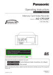
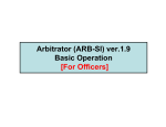
Back-End System Construction
The Back-End System is composed of the Back-End
Server, database server, and Back-End Administrator
and Back-End Client applications. The Back-End
Server receives videos and meta-information from
the Front-End application or the Memory Card Video
Recorder and stores them in its storage area. The
meta-information is registered in the database server.
The Back-End application is composed of two parts,
one for an administrator (Back-End Administrator) and
another for an officer (Back-End Client). The Back-End
Administrator application enables updating of software,
user management, system setting, etc. The BackEnd Client application enables searching for videos
stored in the Back-End Server, playing videos found,
streaming videos, exporting data, etc.
The Back-End System also includes the Service Watch
application, which monitors operation logs of the BackEnd system in real time.
Windows server
Streaming
streaming
Proxy Server
Router
WWAN
Windows server
server
SQL
Server
DB
Storage
Windows server
Wi-Hi
Access
Point
BE
server
Service
Watch
Windows
Windows
BEC-A
BEC-O
ws
v
LAN
Streaming is not available at present. Upgrading is
scheduled for the future.
Overview (continued)
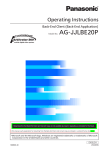
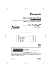
Multi-Server System
Functions
The Back-End system has multiple servers that are
independent of one another, and one Back-End Server
has its own database. The Front-End application can
upload videos to any Back-End Server. When the
Back-End Client user is logged in, the user selects one
of multiple servers, and a search operation is enabled
on the selected Back-End Server only.
The Back-End Administrator application allows an
administrator to make settings for operating the
Memory Card Video Recorder, Front-End applications,
Back-End Administrator application and Back-End
Client application.
Updating software
Firmware of the Memory Card Video Recorder, FrontEnd application, Back-End Administrator application,
and Back-End Client application can be remotely
updated to the latest version.
SQL Server on WMware
DB1 file
BES1 on VMware
Location1
Service Watch
User registration
DB2 file
BES2 on VMware
Service Watch
Administrators and officers who use the Front-End
application, Back-End Administrator application, and
Back-End Client application are registered as users.
Location2
2.AV
1.AV
BEC
Grouping users
District-1(Vehicle)
District-2(Vehicle)
VPU/FE
VPU/FE
1.AV
2.AV
Registered users can be grouped. Once they are
grouped, information for multiple users can be updated
easily.
2.AV
Defining rules
Rules for registering videos to the database can be
defined.
Defining classify tag
Classify tags used for searching for can be defined.
System setup
Setting for the Back-End Server can be made.
Overview (continued)
Operating Environment
A PC that meets the following operating environment is
required for use of this application:
CPU: Intel Core Duo 1.66 GHz or more
(recommended)
RAM: 512 MB or more (for Windows Vista
Business, 1GB or more) (recommended)
Display: 1024 x 768 dot or more
LAN: 1000BASE-T/100BASE-TX
OS: Windows XP Professional Service Pack 3 or
later, Windows Vista Business Service pack 2 or
later
Add on: .Net Framework 3.5 Service Pack 1
Windows Installer3.1
Adobe Reader 8 or 9
Installing/Uninstalling
Installing
Remote updating
The Back-End Administrator application can be
remotely updated when the latest version of the BackEnd Administrator application is registered in the BackEnd Server.
Installing the Back-End
Administrator application
To install the Back-End Administrator application,
the Back-End Server application must be installed.
For installation of the Back-End Server, refer to the
Operating Instructions for the Service Watch.
When the Back-End Administrator application receives
the update module from the Back-End Server, it is
automatically updated upon being restarted.
1. Start the Internet Explorer.
Notes
2. Access to http:// (IP address of the BackEnd Server):12430/Admin.exe.
• If the Interactive services dialog detection dialog box is
displayed, select “Show me the message.”
• If a dialog box prompting you to select Try Again,
Continue, or Exit Installation is displayed, select
Continue.
The Update module is downloaded, and executed.
3. Enter the IP address of the Back-End
Server, and click on [Update].
The License Agreement screen appears.
4. Select “I Agree”.
The Installation Complete screen appears.
5. Click on [Close].
The login dialog box appears.
6. Enter the Server IP address, User,
Password, and click on [Login].
A shortcut icon is placed on the desktop.
Installing/Uninstalling (continued)
Uninstalling
Uninstall the Back-End Administrator application
following the procedures below.
Procedures for Windows XP
1. Click on the [Start] button.
2. Select Control Panel.
3. Double-click on Add or Remove Programs.
The Currently installed programs window opens.
4. Select the program to be uninstalled.
5. Click on the [Remove] button.
A confirmation message appears.
6. Click on the [Yes] button.
Uninstalling of the selected program starts.
Procedures for Windows Vista
1. Click on the [Start] button.
2. Select Control Panel.
3. Double-click on Programs and Features.
The Uninstall or change a program window opens.
4. Select the program to be uninstalled.
5. Click on Uninstall.
The User Account Control window opens.
6. Click on the [Continue] button.
The Uninstall window opens.
7. Click on the [Uninstall] button.
Uninstalling of the selected program starts.
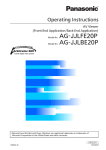
Description of the Screen Displays
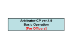
Main Screen
When the login succeeds, the main screen appears.
The main screen contains a toolbar and setting section.
Toolbar
Setting section
Toolbar
Classify button
For displaying the classify setting screen for
defining a classify tag.
(See "Classify Screen," page 18.)
When one of the buttons is clicked on, the screen for
the corresponding function will open.
Config button
①
②
③
④
⑤
⑥
For displaying the configuration screen for setting
the Back-End Server.
(See "Configuration Screen," page 19.)
⑦
Help button
Update button
When this button is clicked, the mouse pointer will
be turned to “→+?”. Clicking on a button or input
field with this pointer will display the description of
the clicked button/input field.
For displaying the remote update screen for
updating software and the settings of the Memory
Card Video Recorder.
(See "Update Screen," page 10.)
Users button
Note
For displaying the user registration screen for
registering users who are enabled to use the BackEnd Administrator application, Back-End Client
application and Front-End application.
(See "Users Screen," page 15.)
If you use Adobe Reader 8 or 9, the description may
not be displayed correctly when you click on a button or
input field.
Groups button
For displaying the group registration screen for
grouping users.
(See "Groups Screen," page 16.)
Rules button
For displaying the evidence rules setting screen for
defining evidence rules applied to the video files
registered in the database.
(See "Rules Screen," page 17.)
Description of the Screen Displays (continued)
Update Screen
When the Update button on the main screen is clicked
on, the remote update screen for updating the FrontEnd application, Back-End application, firmware of the
Memory Card Video Recorder, and recorder settings is
displayed.
①
②
③
④
Front-End Update tab
For displaying the screen for updating the FrontEnd application.
(See "Front-End Update screen," page 11 and
"Updating the Front-End application," page 28.)
Back-End Update tab
For displaying the screen for updating the BackEnd Administrator application, Back-End Client
application.
(See "Back-End Update screen," page 12 and
"Updating the Back-End Administrator and BackEnd Client applications," page 29.)
Recorder Update tab
For displaying the Remote Update screen for
updating firmware of the Memory Card Video
Recorder.
(See "Recorder Update screen," page 13 and
"Updating the firmware of the Memory Card Video
Recorder," page 31.)
Recorder Setting Update tab
For displaying the Remote Update screen for
updating the configuration settings for the Memory
Card Video Recorder.
(See "Recorder Setting Update screen," page 14
and "Updating the recorder settings," page 33.)
10
Description of the Screen Displays (continued)
Front-End Update screen
Select All button
When the Front-End Update tab on the Update
screen is clicked on, the Front-End Update screen
appears. The Front-End application will be updated
by transferring the latest version from the Back-End
Server to the Front-End application via LAN or WLAN.
Clear All button
All Valid check boxes for the Front-End application
shown on the Front-End list are checked.
All Valid check boxes for the Front-End application
shown on the Front-End list are unchecked.
Delete button
(See "Updating the Front-End application," page 28.)
①②
For deleting the Front-End application selected on
the Front-End list from the database.
③
Refresh button
For refreshing the Front-End list.
④ ⑤
⑥ ⑦
Update Version display
For displaying the software version for updating.
Register button
For registering the Front-End application in the
Back-End Server.
Front-End list
For displaying the list of the Front-End application
detected by the Back-End Server. Right-clicking
enables deleting the Front-End application and
refreshing the screen.
Valid: Check the check box, and the corresponding
Front-End application will be updated.
PC Name: Name of the PC with the Front-End
application installed.
Version: The current version of the Front-End
application installed.
Last Update Date/Time: The last applying date
and time of the Front-End applications.
Status: The update status of the Front-End
applications.
• Wait for Update
• Updating
• Updated
• Disconnected
11
Description of the Screen Displays (continued)
Back-End Update screen
Delete button
For deleting the Back-End application selected on
the Back-End list from the database.
When the Back-End Update tab on the Update
screen is clicked on, the Back-End Update screen
appears. The Back-End Administrator application
and/or the Back-End Client application will be updated
by transferring the latest version from the Back-End
Server to the Back-End Administrator and Back-End
Client applications.
(See "Updating the Back-End Administrator and BackEnd Client applications," page 29.)
Refresh button
For refreshing the Back-End list.
for Back-End
Administrator
for Back-End
Client
Update Version display
For displaying the software version for updating.
Register button
For registering the Back-End Administrator or BackEnd Client application to the Back-End Server.
Back-End list
For displaying the list of the Back-End Administrator
or Back-End Client application detected by the
Back-End Server. Right-clicking enables deleting
the Back-End Administrator or Back-End Client
application and refreshing the screen.
PC Name: Name of the PC with the Back-End
Administrator or Back-End Client application
installed.
Version: The current version of the Back-End
Administrator or Back-End Client application
installed.
Last Update Date/Time: The last applying date
and time of the Back-End Administrator or BackEnd Client application.
Status: The update status of the Back-End
Administrator or Back-End Client application.
• Wait for Update
• Updating
• Updated
• Disconnected
12
Description of the Screen Displays (continued)
Recorder Update screen
connecting with the Front-End application.
IP Address: The IP address of the Memory Card
Video Recorder.
When the Recorder Update tab on the Update screen
is clicked on, the Recorder Update screen appears.
The firmware of the Memory Card Video Recorder
is updated by transferring the latest version from
the Back-End Server directly or via the Front-End
application to the recorder, using LAN or WLAN.
Status: The update status of the Memory Card
Video Recorder.
• Wait for Update
• Updating
• Updated
• Disconnected
(See "Updating the firmware of the Memory Card Video
Recorder," page 31.)
①
②
Select All button
③
All Valid check boxes for the Memory Card Video
Recorders shown on the Recorder list are checked.
Clear All button
All Valid check boxes for the Memory Card
Video Recorders shown on the Recorder list are
unchecked.
Delete button
For deleting the Memory Card Video Recorder
selected on the Recorder list.
Refresh button
For updating the Recorder list.
④ ⑤
⑥
⑦
Update Version display
For displaying the software version for updating.
Register button
For registering the firmware for the Memory Card
Video Recorder in the Back-End Server.
Recorder list
For displaying the list of the Memory Card Video
Recorders detected by the Back-End Server. Rightclicking enables deleting the firmware or refreshing
the screen.
Valid: Check the check box, and the corresponding
firmware will be updated.
VehicleID: The Vehicle ID. (If the Valid check box is
unchecked, single-clicking enables editing.)
Last Update Date/Time: The last applying date
and time of the firmware of the Memory Card
Video Recorder.
Recorder Version: The current version of the
firmware of the Memory Card Video Recorder.
Model: The model name of the Memory Card Video
Recorder (available on the AG-CPD20P only).
Serial: The serial number of the Memory Card
Video Recorder (available on the AG-CPD20P
only).
MAC Address: The MAC address of the Memory
Card Video Recorder's network interface for
13
Description of the Screen Displays (continued)
Recorder Setting Update screen
Last Update Date/Time: Displays the last applying
date and time of the setting of the Memory Card
Video Recorder.
When the Recorder Setting Update tab on the Update
screen is clicked on, the Recorder Setting Update
screen appears. The configuration settings of the
Memory Card Video Recorder will be updated via LAN
or WLAN.
Recorder Version: The current version of the
firmware of the Memory Card Video Recorder.
Model: The model name of the Memory Card Video
Recorder (available on the AG-CPD20P only).
(See "Updating the recorder settings," page 33.)
① ② ③ ④
Serial: The serial number of the Memory Card
Video Recorder (available on the AG-CPD20P
only).
⑤
MAC Address: The MAC address of the Memory
Card Video Recorder's network interface for
connecting with the Front-End application.
IP Address: The IP address of the Memory Card
Video Recorder.
Status: The update status of the Memory Card
Video Recorder.
• Wait for Update
• Updating
• Updated
• Disconnected
⑥ ⑦
Select All button
⑧ ⑨
All Valid check boxes for the Memory Card Video
Recorders shown on the Recorder list are checked.
Settings button
Clear All button
Click to display the Recorder Setting screen.
Adding, editing or deleting settings for the Memory
Card Video Recorder is enabled.
All Valid check boxes for the Memory Card
Video Recorders shown on the Recorder list are
unchecked.
Add Group button
Delete button
A new Memory Card Video Recorder group is
created.
For deleting the Memory Card Video Recorder
selected on the Recorder list.
Edit Group button
Refresh button
For editing the list of the Memory Card Video
Recorders belonging to the group.
For updating the Recorder list.
Delete Group button
For deleting a Memory Card Video Recorder group.
Recorder list
For displaying the list of the Memory Card Video
Recorders detected by the Back-End Server. Rightclicking enables deleting the firmware or refreshing
the screen.
Valid: Check the check box, and the corresponding
recorder setting will be updated.
VehicleID: The Vehicle ID. (If the Valid check box is
unchecked, single-clicking enables editing.)
Group: For displaying the group to which a
Memory Card Video Recorder belongs.
Recorder Setting Name: For selecting the setting
applied to the Memory Card Video Recorder
from among predefined settings or None setting.
If the Memory Card Video Recorder belongs
to a group, the selected setting is applied to all
recorders in the group.
14
Description of the Screen Displays (continued)
Users Screen
When the Users button on the main screen is clicked
on, the user registration screen is displayed. On this
screen, registered users are listed. Adding and deleting
users and changing user information are enabled.
(See "Registering Users," page 55.)
①
②
③
④
⑤
⑥
Users List
For displaying the User ID and name registered
to the Back-End Server. Right-clicking enables
displaying the property and adding and deleting
data.
Add button
For adding users.
Add by AD button
For adding users using the Active Directory data.
Property button
For displaying the property screen for showing and
editing the user data.
Delete button
For deleting the users selected on the User list.
Import button
For registering the user and group information
stored on external media to the database.
Export button
For exporting the user and group information
registered in the Back-End Server to external
media.
15
⑦
Description of the Screen Displays (continued)
Groups Screen
When the Groups button on the main screen is
clicked on, the group setting screen is displayed. On
this screen, registered groups are listed. Adding and
deleting groups and changing group information are
enabled.
(See "Registering Groups," page 62.)
①
②
③
④
⑤
⑥
Groups List
For displaying the list of group name and group
note registered in the Back-End Server. Rightclicking enables displaying the property, and adding
and deleting groups.
Add button
For adding groups.
Add by AD button
For adding groups using the Active Directory data.
Property button
For displaying the property screen for showing and
editing the group data.
Delete button
For deleting the groups selected on the Groups list.
Import button
For registering the user and group information
stored on external media to the database.
Export button
For exporting the user and group information
registered in the Back-End Server to external
media.
16
⑦
Description of the Screen Displays (continued)
Rules Screen
When the Rules button on the main screen is clicked
on, the evidence rule setting screen is displayed. On
this screen, rules are listed. Adding and deleting rules
and changing rules information are enabled.
(See "Setting Evidence Rules," page 64.)
①
②
③
④
⑤
Rule Tree
For displaying the rules registered in the BackEnd Server in tree format. Right-clicking enables
adding, editing, or deleting the rules or opening or
closing all rules.
Add button
When this button is clicked on, the Rule screen
appears, on which rules can be added.
Edit button
When this button is clicked on, the Rule screen
appears, on which rules can be edited.
Delete button
For deleting rules.
Apply button
For registering the edited rules in the database.
Cancel button
For canceling editing of the rules.
17
⑥
Description of the Screen Displays (continued)
Classify Screen
When the Classify button on the main screen is clicked
on, the classify setting screen is displayed. On this
screen, classify tags are listed. Creating, deleting, and
changing classify tags are enabled.
(See "Setting Classify Information," page 69.)
①
)
②
③
④
Classify List
For displaying the list of the Classify tag registered
in the database. Right-clicking enables adding,
editing, and deleting Classify tag. Double-clicking
enables editing the Classify tag.
Add button
For displaying the Input Classify Tag screen for
adding a classify tag.
Edit button
For displaying the Input Classify Tag screen for
editing a classify tag.
Delete button
For deleting the Classify Tags.
18
Description of the Screen Displays (continued)
Configuration Screen
When the Config button on the main screen is clicked
on, the system configuration screen is displayed.
(See "System Setup," page 70.)
①
②
③
④
⑤
⑥
Drive setting tab
⑦
Apply button
For displaying the drive setting screen for setting
the destination to register video files.
(See "Drive setting screen," page 20, and "Drive
Setting," page 71.)
All settings and changes made on each setting
screen will be registered to the database.
Cancel button
For canceling all settings and changes made on
each setting screen.
Log setting tab
For displaying the log setting screen for setting log
output.
(See "Log setting screen," page 21, and "Log
Setting," page 74.)
Schedule setting tab
For displaying the schedule setting screen.
(See "Schedule setting screen," page 22, and
"Schedule Setting," page 76.)
Password setting tab
For displaying the password setting screen for
setting the password policy.
(See "Password setting screen," page 23, and
"Setting the Password," page 78.)
DB/Network setting tab
For displaying the database/network setting screen.
(See "DB/Network setting screen," page 24, and
"Setting the Database and Network," page 80.)
19
Description of the Screen Displays (continued)
Drive setting screen
Add button
For adding a new folder in which videos are to be
stored.
When the Drive setting tab on the Config screen is
clicked on, the drive setting screen is displayed.
(See "Drive Setting," page 71.)
Delete button
For deleting a folder selected on the Library.
Archive Setting
ⓐ
①
ⓒ
②
ⓑ
③
For setting the Archive folder.
Archive Folder
④
For displaying the full folder path for the Archive
folder.
Minimum Free Space
Enter the minimum free space. When the
free space is less than this size, the e-mail is
automatically sent to the users who belong to the
group specified in “Alert Setting”. (See “Schedule
setting screen,” page 22.)
Video Inbox Setting
ⓐ
ⓑ
Browse button
For specifying the folder path for the Video Inbox
where temporarily stores the video files uploaded
from the Front-End application, Memory Card Video
Recorder, or Back-End Client application.
For opening the Server Folder Setting dialog box
for selecting the Archive Folder.
Unprocessed video setting
ⓐ
Video Inbox
For displaying the folder path for the Video Inbox.
ⓒ
Browse button
The Server Folder Setting dialog box opens to
select the Video Inbox.
ⓑ
Library Setting
ⓐ
ⓑ
ⓒ
For specifying a folder in which videos are to be
stored.
Settings for the Unprocessed Video Folder will be
made.
When the video is verified and unprocessed, e-mail
is automatically sent to the users who belong to the
group specified in “Alert Setting.” (See “Schedule
setting screen,” page 22.) Consult your supplier.
Unprocessed Video Folder
For displaying the full folder path for the
Unprocessed Video Folder.
Library
For displaying the list of the folder path of folders
where video files are to be moved from the Video
Inbox. Right-clicking enables adding or deleting the
folder path.
Unprocessed video save period
The retention period of the unprocessed video file
is fixed to unlimited.
Browse button
Path: The full path for the folders which store the
video files.
For opening the Server Folder Setting dialog box
for selecting the Unprocessed Video Folder.
Minimum Free Space: The minimum disk space.
When free space is less than this size, e-mail is
automatically sent to the users who belong to the
group specified in “Alert Setting.” (See “Schedule
setting screen,” page 22.)
Free Space: The current disk space.
20
Description of the Screen Displays (continued)
Log setting screen
When the Log setting tab on the Config screen is
clicked on, the log setting screen is displayed.
(See " Log Setting," page 74.)
①
②
Operation log setting
ⓐ
Settings for the user operation log will be made.
Log Retention Period
For specifying the retention period of the user
operation log. If the Log Retention Period is set to
“0”, the retention period will be unlimited.
Front-End Application/Recorder Log setting
ⓐ
ⓑ
ⓒ
Settings for the log of the Front-End application and
Memory Card Video Recorder will be made.
Root Path of Front-End/Recorder
For displaying the full path of the Front-End and
Memory Card Video Recorder log files.
Capacity restrictions
For setting the capacity of the Front-End application
and Memory Card Video Recorder log files. The log
is deleted from the oldest one when the capacity
exceeds this value.
Browse button
For opening the Server Folder Setting dialog
box for selecting the Root Path of the Front-End
application and Recorder.
21
Description of the Screen Displays (continued)
Schedule setting screen
Alert Setting
ⓐ
When the Schedule setting tab on the Config screen is
clicked on, the schedule setting screen is displayed.
(See " Schedule Setting," page 76.)
ⓑ
Alert settings will be made.
①
Set the Time of no connection to
Front-End/Recorder to send e-mail.
②
If a certain recorder has not uploaded video files
exceeding the specified days, the warning e-mail is
sent to the specified group.
Default setting: 7 days
③
Send to
The destination of e-mail is specified.
Default setting: Empty
Schedule setting
ⓐ
ⓑ
For setting the schedule.
Work Start Time
For entering the start time of the batch processing.
Default setting is 00:00.
Work Time
For entering the time of the batch processing.
Setting values: 1 hour, 2 hour, 3 hour, 5 hour, Until
End.
Default setting: 2 hour
Case File Records Retention
When checked, the longest retention period from
among all files associated to the case file will be
applied.
22
Description of the Screen Displays (continued)
Password setting screen
Login to Back-End using your
operating system login.
When the Password setting tab on the Config screen is
clicked on, the password setting screen is displayed.
(See "Setting the Password," page 78.)
When checked, the login screen appears with the
user name and password set as default if the user
name being logged in Windows is registered in the
Back-End application.
①
②
Enable password policy
ⓐ
ⓑ
ⓒ
ⓓ
For setting if password policy is used or not.
The use of password length
For setting if restriction of character length for a
password is used or not. If checked, the restriction
shown below will be valid.
Minimum: Minimum length.
Maximum: Maximum length.
The use of both upper and lower case
letters
For setting the case sensitivity for a password.
When checked, it is enabled.
Inclusion of one or more numerical
digits
For setting if the password should include numerical
digits or not. When checked, a password should
include numerical digits.
The use of password duration
For setting the effective period of a password. The
password is requested to be changed at the end of
the period set here. When checked, the password
time-limit is specified. Empty or "0" means
unlimited. Enter the period in the box below.
When unchecked, this restriction will not be applied.
Login settings
ⓐ
For setting the login
23
Description of the Screen Displays (continued)
DB/Network setting screen
Port setting
When the DB/Network setting tab on the Config screen
is clicked on, the database and network setting screen
is displayed.
(See "Setting the Database and Network," page 80.)
ⓐ
ⓑ
ⓒ
For setting the port
Back-End Server Destination
Connect to Back-End Client/Administrator
(TCP): For confirming the port number for
communicating the Back-End Administrator
or Back-End Client application and Back-End
Server to process the request such as Login,
Video search, etc.
Update Back-End Client/Administrator (TCP):
For confirming the port number to update the
Back-End Administrator or Back-End Client
module from the Back-End Server.
Update from Front-End (TCP): For confirming
the port number to update the module for an
administrator from the Back-End Server.
①
②
③
④
⑤
Database setting
Streaming Proxy Destination
ⓐ
ⓑ
Connect to Back-End Client (TCP): For
confirming the port number of the streaming
proxy server to stream videos on the Back-End
Client application.
Streaming Data (UDP): For confirming the port
number of the streaming proxy server to transfer
videos from the Front-End application or the
Memory Card Video Recorder.
Setting for the database will be made.
SQL server
For setting the database server to be connected.
The database servers detected automatically will
be displayed on the dropdown list.
Database
Back-End Client Destination
For setting the database.
Database managed by the specified database
server is displayed. Select the database from the
dropdown list.
Streaming:
Foravailable
confirming
the port number
of the
Streaming
is not
at present.
Upgrading
is
Back-End
Client
application
to
transfer
videos
scheduled for the future.
from the streaming proxy server.
Streaming Proxy setting
Streaming is not available at present. Upgrading is
For displaying
thefuture.
IP addresses for the streaming
scheduled
for the
server.
System Name
For communicating the Back-End Server with
the Memory Card Video Recorder directly. The
communication is enabled only with the recorder
having the system name set here.
24
Description of the Screen Displays (continued)
IP Address Setting
ⓐ
ⓑ
ⓒ
ⓓ
ⓒ
ⓓ
For setting the IP address.
Front-End IP Address
For displaying the IP address for communicating
with the Memory Card Video Recorder via the
Front-End application.
Recorder IP Address
For displaying the IP address of the Memory
Card Video Recorder for communicating with the
Memory Card Video Recorder.
Add button
When this button is clicked on, the IP Address
Setting dialog box appears. IP addresses can be
added.
Delete button
For deleting the IP address selected on the IP
address list.
25
Startup and Termination
Starting up
1. Turn on the PC.
2. Double-click on the Back-End Administrator
icon on the desktop.
The Login screen is displayed.
3. Enter the IP address or Host name of the
Back-End Server in the Back-End Server
field.
If you have logged in before, you can select it from
the dropdown list.
4. Enter the User ID.
If you have logged in before, you can select the
User ID from the dropdown list.
5. Enter the password.
6. Click on [Login].
The Main screen is displayed.
Canceling login
Click on [Exit].
26
Startup and Termination (continued)
Terminating
Click on the close button at the upper right on the Main
screen. The application is terminated, and the screen is
closed.
Note
While updating, the error message appears, and the
application cannot be terminated.
27
Operations
Updating
Registering the Front-End application
Only one version of the Front-End application can be
registered in the Back-End Server. When a new version
is registered, the old one will be deleted.
The Back-End Administrator application can remotely
update the Front-End application and Memory Card
Video Recorder, as well as the Back-End system itself.
Updating the Front-End application
The latest version of the Front-End application is sent
to the PC with the Front-End application installed via
wired or wireless LAN for updating the application.
Click on the Front-End Update tab. The Front-End
Update screen appears. On this screen, confirmation
of the update status of the Front-End application and
registration of the Front-End application to the BackEnd Server are enabled.
1. Click on [Register].
The file selection dialog box appears.
2. Select the update module for the Front-End
application.
3. Click on [Open].
The update module is checked if it is correct. The
application is registered if the module is correct.
If it is not correct, an error message appears.
Updating the Front-End Update screen
Click on [Refresh]. The screen will be updated.
Confirming the update status of the .
Front-End applications
On the Front-End Update screen, a list of PCs on
which Front-End application is running detected by the
Back-End Server is displayed. On the list, the version
and date and time of last update of each Front-End
application are displayed.
In the Update Version field, the latest version appears.
Updating the Front-End application
If the Valid check box is checked, the Back-End Server
detects the checked PC and updates it automatically.
The version of the updating software is displayed in the
Update Version field.
Note that without registering the Front-End application,
the Valid check box cannot be checked, and [Select All]
and [Clear All] are not active.
Selecting all Front-End applications
Click on [Select All]. All Valid check boxes will be
checked.
Clearing selection of all Front-End
applications
Click on [Clear All]. All Valid check boxes will be
unchecked.
28
Operations (continued)
Updating the Back-End
Administrator and Back-End Client
applications
Deleting PC on which Front-End
application is running
On the Back-End Update screen, updating of the BackEnd Administrator application and Back-End Client
application is enabled. Upper half of the screen is for a
Back-End Administrator application, and the lower half
is for a Back-End Client application.
Click on the Back-End Update tab. The Back-End
Update screen appears.
1. Select PCs to be deleted on the Front-End
Application list.
2. Click on [Delete].
A confirmation dialog box is displayed.
3. Click on [Yes].
The selected PCs will be deleted from the list.
Cancel deleting
Confirming the update status of the BackEnd Administrator and Back-End Client
applications
Click on [No] in the confirmation dialog box.
On the Back-End Update screen, a list of PCs on which
Back-End Administrator or Back-End Client application
is running, registered in the Back-End Server is
displayed. On the list, the version and date and time of
last update of each Back-End Administrator and BackEnd Client application are displayed.
In the Update Version field, the latest version appears.
Updating the Back-End Administrator or
Back-End Client applications
Upon the start-up of the Back-End Administrator
or Back-End Client application, the version of the
application registered in the Back-End Server is
checked. If the latest version is detected, the BackEnd Administrator or Back-End Client application is
automatically updated. The version of the updating
software is displayed in the Update Version field.
29
Operations (continued)
Registering the Back-End Administrator or
Back-End Client application
Deleting PC on which Back-End
Administrator or Back-End Client
application is running
Only one version of the Back-End Administrator and
Back-End Client applications can be registered in the
Back-End Server. When a new version is registered,
the old one will be deleted.
1. Select PCs to be deleted on the BackEnd Administrator or Back-End Client
application list.
1. Click on [Register].
The file selection dialog box appears.
2. Click on [Delete].
2. Select the update module for the BackEnd Administrator or Back-End Client
application.
A confirmation dialog box is displayed.
3. Click on [Yes].
The selected PCs will be deleted from the list.
3. Click on [Open].
Cancel deleting
The update module is checked if it is correct. The
application is registered if the module is correct.
If it is not correct, an error message appears.
Click on [No] in the confirmation dialog box.
Updating the Back-End Update screen
Click on [Refresh]. The screen will be updated.
30
Operations (continued)
Updating the firmware of the Memory
Card Video Recorder
Editing Vehicle ID
Only when the Valid check box is not checked, Vehicle
ID can be edited.
Click on the cell to be edited.
If the Valid check box is checked, Vehicle ID is not
updated when the Memory Card Video Recorder is
detected. It cannot be edited.
The firmware of the Memory Card Video Recorder is
updated via wired or wireless LAN.
Click on the Recorder Update tab. The Recorder
Update screen appears.
Updating the recorder
When the Valid check box is checked, the BackEnd Server detects the checked Memory Card Video
Recorder and transfers the firmware automatically.
However, Field5 (Source) in the database is not
updated.
To update the Memory Card Video Recorder after
firmware transfer, reboot it.
Selecting all recorders
Click on [Select All]. All Valid check boxes will be
checked.
Clearing selection of all recorders
Click on [Clear All]. All Valid check boxes will be
unchecked.
Confirming the update status of the
recorder
On the Recorder Update screen, a list of the firmware
of the Memory Card Video Recorder detected by the
Back-End Server is displayed.
The Back-End Server identifies a Memory Card Video
Recorder by using the MAC address of the recorder
for connecting to the Front-End application. When a
recorder is detected for the first time, it is registered in
the database. If the Valid check box is not checked, the
Back-End Server updates the items on the recorder list
each time it detects the recorder.
Note that the recorder list on the screen is not updated
before clicking on the [Refresh] button.
In the Update Version field, the latest version appears.
31
Operations (continued)
Registering firmware
Deleting the recorder
Only one version of the firmware can be registered
in the Back-End Server. When a new version is
registered, the old one will be deleted.
1. Select a recorder to be deleted on the
Recorder Firmware list.
1. Click on [Register].
2. Click on [Delete].
The file selection dialog box appears.
A confirmation dialog box is displayed.
2. Select the update firmware for the recorder.
3. Click on [Yes].
The selected recorder will be deleted from the list.
3. Click on [Open].
The update firmware is checked if it is correct. The
application is registered if the firmware is correct.
If it is not correct, an error message appears.
Cancel deleting
Click on [No] in the confirmation dialog box.
Updating the Recorder Update screen
Click on [Refresh]. The screen will be updated.
32
Operations (continued)
Updating the recorder settings
Creating the Memory Card Video Recorder
settings
The configuration settings for the Memory Card Video
Recorder can be updated via LAN or Wireless LAN.
Setting items are the same as those set in administrator
setup of the Front-End application.
If Memory Card Video Recorders are grouped, the
settings on all recorders belonging to a group will be
updated at one time.
When the Back-End Server is installed, the recorder
setting is created with the name "Default recorder
settings". The settings can be edited and be saved with
a different name, which enables creating and saving
multiple recorder settings.
Click on the Recorder Setting Update tab. The
Recorder Setting Update screen appears.
1. Click on [Settings].
The Recorder Setting screen is displayed.
2. Click on [Add].
The editing screen for the Recorder Setting is
displayed.
①②
③
Setting Name: Name of the Memory Card
Video Recorder settings
Item: Setting category
Setting section
33
Operations (continued)
Editing the Memory Card Video Recorder
settings
3. Enter the name of settings to be created in
the Recorder Setting Name field.
4. Select a category to be set on the Item list.
5. Make necessary settings on the setting
section.
(See "Memory Card Video Recorder Configuration
Setting Screen," page 38.)
6. Click on [OK].
The settings are registered, and the Recorder
Setting screen is updated.
Note
If you change the displayed configuration setting screen
without clicking on [OK] after changing settings, “Save
and Apply Changes?” appears. Click on [OK] then change
the screen.
1. Click on [Settings].
The Recorder Setting screen is displayed.
2. Select a Recorder Setting Name to be
edited on the Recorder Setting list.
3. Click on [Edit].
The editing screen for the Recorder Setting is
displayed.
4. Edit the settings.
5. Click on [OK].
The settings are updated, and the Recorder Setting
screen is updated.
6. Click on [Cancel].
34
Operations (continued)
Deleting the Memory Card Video Recorder
settings
Grouping the Memory Card Video
Recorders
If multiple Memory Card Video Recorders are grouped,
the settings on all recorders belonging to a group will
be created and changed.
1. Click on [Settings].
The Recorder Setting screen is displayed.
2. Select a Setting Name to be deleted on the
Recorder Setting list.
1. Click on [Add Group].
3. Click on [Delete].
The Recorder Group screen is displayed.
A confirmation dialog box is displayed.
2. Enter the group name in the Group Name
field.
4. Click on [Yes].
The selected setting is deleted, and the Recorder
Setting screen is updated.
5. Click on [Close].
Cancel deleting
Click on [No] in the confirmation dialog box.
3. Select Vehicle IDs to be grouped on the
Vehicle ID and Group List.
Multiple Vehicle IDs can be selected.
4. Click on [>>].
The Vehicle IDs selected in Step 3 moves to the
Vehicle ID list.
5. Click on [OK].
A Group is created, and the Recorder Group screen
is closed. The created group is registered in the
database.
35
Operations (continued)
Description of the Record Group screen
Editing the Memory Card Video Recorder
group
①
②
③
Group Name: Enter the group name.
Vehicle ID and Group List: Vehicle ID and their
group name that do not belong to the group
displayed in Group Name are listed.
Vehicle ID: Vehicle IDs that belong to the group
displayed in Group Name are listed.
1. Select a Memory Card Video Recorder on
the Recorder Setting Update screen.
2. Click on [Edit Group].
The Recorder Group screen is displayed.
3. Select a Vehicle ID to be added to or
deleted from the group.
To add a recorder to the group: Select a Vehicle
ID on the Vehicle ID and Group List then click on
[>>].
To delete a recorder from the group: Select a
Vehicle ID on the Vehicle ID list then click on [<<].
Multiple Vehicle IDs can be selected.
4. Click on [OK].
A Group editing operation is finished, and the
Recorder Group screen is closed. The edited group
is registered in the database.
36
Operations (continued)
Deleting a group
1. Select a Memory Card Video Recorder with
the Group to be deleted on the Recorder
Setting Update screen.
Multiple recorders can be selected.
3. Click on [Delete Group].
A confirmation dialog box is displayed.
4. Click on [Yes].
The group to which the Memory Card Video
Recorder selected in Step 1 belongs is deleted, and
the database is updated.
Cancel deleting
Click on [No] in the confirmation dialog box.
37
Operations (continued)
Memory Card Video Recorder Configuration Setting Screen
Note
The default settings for various items are shown on the
Setup list on pages 83 to 97.
Admin Password screen
②
①
③
④ ⑤
Password
For inputting an administrator password.
Retype Password
Re-enter the same string of password input in the
Password field for reconfirmation.
Item list
A list of the setting screens is displayed. Clicking on
a screen name will display the corresponding setting
screen.
OK button
For changing the settings of the Memory Card Video
Recorder to those set in the Config screen.
Cancel button
For canceling changes.
38
Operations (continued)
Allocation (Video/Audio) screen
①
②③
④
⑤
Resolution/RecordRate
Connection Camera
ⓐ
ⓑ
ⓐ
Main
The resolution and bit rate of the main video can be
set.
Setting values: D1 HI (720x480, high quality
mode), D1 STD (720x480, standard quality
mode), D1 10 (720x480, 10 frames/second), CIF
(352x240, low quality mode)
Camera1, Camera2, Camera3, Camera4,
Camera5, Camera6
Set if a camera is connected to each of [CAMERA 1],
[2], [3], [4], [5], and [6] connectors on the Memory
Card Video Recorder.
When a camera is connected, set to ON, and when
it is not connected, set to OFF.
Sub
The resolution and bit rate of the sub video can be
set.
Setting values: D1 HI (720x480, high quality
mode), D1 STD (720x480, standard quality
mode), D1 10 (720x480, 10 frames/second), CIF
(352x240, low quality mode)
Note
If either of the Main or Sub Resolution/RecordRate is set
to “D1 10”, the other is also set to “D1 10”.
39
Operations (continued)
Preset Settings
Audio in Select
ⓐ
ⓑ
Select the type of microphones connected to
each of [AUDIO IN 1], [2], [3], and [4] connectors
on the Memory Card Video Recorder or turn the
microphone off.
For setting the channel mode and camera
connection pattern for Preset 1, Preset 2, and
Preset 3.
(See “Camera Connection and Combination of
Cameras” on page 118.)
Setting values: Mic, Wireless Mic, Off
Init Audio Rec after power ON
Form
Set the channel mode.
Pattern
Set the camera connection pattern.
Set the audio recording status upon startup of the
Memory Card Video Recorder.
The setting will be applied to all four audio
channels.
Setting values for Form and Pattern:
Pattern
Main 1, Sub Main 2, Sub Main 3, Sub 2Channels
Main 1, Sub 2
Main 1, Sub 3
Main 2, Sub 3
4Channels QUAD
Main -, Sub 1456
Main -, Sub 2456
Main -, Sub 3456
4Channels PANORAMA Main -, Sub 1456
Main -, Sub 2456
Main -, Sub 3456
5Channels QUAD
Main 1, Sub 2456
Main 1, Sub 3456
Main 2, Sub 3456
Main 3, Sub 2456*1
5Channels PANORAMA Main 1, Sub 2456
Main 1, Sub 3456
Main 2, Sub 3456
Main 3, Sub 2456*1
NONE*2
1Channel
Form
Setting values: ON, OFF, LAST
*1 This setting is enabled when the camera connected
to the [CAMERA 1] connector is set to OFF.
*2 “None” is not selectable for Preset1 unless all
camera connections are set to OFF.
40
Operations (continued)
Camera1 screen
①
②
Camera1
Auto Zoom End Position
Set the automatic zooming end magnification.
Perform the settings for the color camera that is
connected to the [CAMERA 1] connector on the
Memory Card Video Recorder.
Setting values: 1, 2, 3, 4, 5, 7, 10, 15, 22, LAST
Zoom Limit
ⓐ
Set the maximum zoom magnification.
ⓑ
Setting values: 22, 220
ⓒ
ⓔ
ⓓ
ⓕ
AGC Level
Set the level of the camera input gain control.
Setting values: LOW, MID, HIGH, OFF
ⓖ
Flip
ⓗ
Set if flipping of the camera output image will be
performed or not.
Setting values: ON, OFF
ⓘ
Auto Focus
Set a focusing method of the camera.
IR Level
Setting values: PRESET, DISABLE, AUTO
Set the IR level for automatic switching of the IR
function.
Setting values: LOW, HIGH
IR Time [s]
Set the detection time for automatic switching of
the IR function.
Setting values: 10, 30, 60, 300 seconds
Auto Zoom Magnification
Set the maximum zoom magnification during
automatic zooming.
Setting values: 1, 2, 3, 4, 5, 7, 10, 15, 22
Auto Zoom Time [s]
Set the keeping time of the maximum zoom
magnification during automatic zooming.
Setting values: 3, 5, 8 seconds
41
Operations (continued)
Init Camera1 Settings after power ON
ⓐ
ⓑ
ⓒ
ⓓ
ⓔ
The status of the color camera when it is turned on
can be set.
Init Backlight
Set the backlight compensation function setting
upon power-on of the Memory Card Video
Recorder.
Setting values: ON, OFF, LAST
Init IR Mode
Set the IR mode upon power-on of the Memory
Card Video Recorder.
Setting values: ON, OFF, AUTO, LAST
Init Camera 1 LED
Set the status of the [REC] lamp on the camera
connected to the [CAMERA 1] connector on the
Memory Card Video Recorder upon power-on.
Setting values: ON, OFF, LAST
Init AE Shift
Set the brightness of images upon power-on of the
Memory Card Video Recorder.
Setting values: 2, 1, 0, -1, -2, LAST
Init LPR Mode
Set if the LPR mode is enabled or not upon poweron of the Memory Card Video Recorder.
Setting values: ENABLE, DISABLE
42
Operations (continued)
Date/Time screen
①
②
Time Zone
③
④
⑤
Day/Night View
Set the time zone.
Select if Day and Auto Switch Night views are
automatically switched or not. When a check mark
is placed in the box, Day/Night views are switched
automatically.
Setting values:
Hawaii Standard Time
Yukon Standard Time
Note
Yukon Daylight Saving Time
This setting is enabled on the Front-End application only.
Pacific Standard Time
Pacific Daylight Saving Time
Switch to Day View at
Mountain Standard Time
Mountain Daylight Saving Time
Set the time when Night mode is changed to Day
mode.
Central Standard Time
Setting range: 00:00:00 AM-11:59:59 PM
Switch to Night view at
Central Daylight Saving Time
Set the time when Day mode is changed to Night
mode.
Eastern Standard Time
Eastern Daylight Saving Time
Setting range: 00:00:00 AM-11:59:59 PM
Atlantic Standard Time
Atlantic Daylight Saving Time
Note
Asia Tokyo
Displayed time (12/24-hour system) depends on the
setting on your PC.
Date/Time Style
Set the display pattern of date and time.
Setting values: ISO, USA
43
Operations (continued)
File Transfer screen
①
②
③
Upload
Certification
ⓐ
ⓑ
ⓐ
System Name
Auto Upload is Enabled
Set the system name of the Memory Card Video
Recorder within 50 characters. When the Recorder
directly communicates with the Back-End system,
the communication is enabled only when the
name set here and that registered in the Back-End
system are the same.
Automatic uploading is enabled when a check mark
is placed in the box.
Server IP Address for Manual Upload
Set the IP address of the Back-End Server for
manual uploading.
Note
This setting is enabled on the Front-End application only.
Export/DVD Burn
ⓐ
The method to delete videos on the
recorder
Select how to delete video files from the Memory
Card Video Recorder after data exporting or DVD
burning.
Setting values: Force, Confirmation
Exporting from the Front-End application is not
available at present. Upgrading is scheduled for
the future.
44
Operations (continued)
Network screen
①
②
③
④
Streaming
IP Address
Set the IP address for the LAN port on the Memory
Card Video Recorder that is used for connecting to
the Front-End application.
This setting is enabled when DHCP is set to OFF.
ⓐ
ⓑ
Subnet Mask
ⓒ
Set the subnet mask for the LAN port on the
Memory Card Video Recorder that is used for
connecting to the Front-End application.
This setting is enabled when DHCP is set to OFF.
Server IP Address List
Set the IP Addresses of the Back-End Server
for streaming. Up to 5 IP addresses can be
registered. The Front-End application periodically
sends packets to these IP addresses. The BackEnd Server recognizes the sender of the received
packets as a streaming target. A Front-End
application can connect with a single Back-End
Server at a time.
No IP address is set as default.
Gateway
Set the default gateway for the LAN port on the
Memory Card Video Recorder that is used for
connecting to the Front-End application.
This setting is enabled when DHCP is set to OFF.
Recorder (UPLOAD LAN)
ⓐ
Alert Streaming
If a check mark is placed in the box, when streaming is
in progress in the Back-End Administrator application,
that is indicates on the Front-End application screen.
This function is enabled as default.
ⓒ
ⓓ
The settings for the wired LAN port on the Memory
Card Video Recorder that is used for connecting to
the Back-End Server can be performed.
Resolution
Streaming
is not available
at present.
Upgrading is
Set the resolution
of the video
in streaming.
scheduled for the future.
Setting values: QCIF (176x112), CIF (352x240)
ⓑ
DHCP
Select if the IP address for the wired LAN port on
the Memory Card Video Recorder will be obtained
from the DHCP server or not.
Setting values: OFF, Client
Recorder (PC LAN)
IP Address
ⓐ
ⓑ
ⓒ
Set the IP address. This setting is enabled when
DHCP is set to OFF.
ⓓ
Subnet Mask
DHCP
Set the subnet mask. This setting is enabled when
DHCP is set to OFF.
Set if the LAN port on the Memory Card Video
Recorder that is used for connecting to the FrontEnd application is to operate as a DHCP server or
not.
Setting values: OFF, Server1, Server2, Server3,
Server4
Gateway
Set the default gateway. This setting is enabled
when DHCP is set to OFF.
45
Operations (continued)
Recorder (USB WIRELESS LAN)
ⓐ
ⓑ
ⓒ
Access Point Setting screen
This screen is displayed when the [Property] button is
pressed on the Network screen.
ⓓ
ⓗ
ⓘ
ⓐ
ⓑ
ⓔ
ⓕ
ⓖ
ⓒ
The settings for the USB wireless LAN port on
the Memory Card Video Recorder that is used for
connecting the Back-End Server can be performed.
ⓓ
ⓔ
DHCP
Select if the IP address for the USB wireless LAN
port on the Memory Card Video Recorder will be
obtained from the DHCP server or not.
Setting values: OFF, Client
IP Address
ⓕ
Set the IP address. This setting is enabled when
DHCP is set to OFF.
ⓖ
Access Point
Subnet Mask
Select if the access point settings are enabled or
not.
Setting values: ENABLE, DISABLE
Set the subnet mask. This setting is enabled when
DHCP is set to OFF.
Gateway
SSID
Set the default gateway. This setting is enabled
when DHCP is set to OFF.
Set the SSID for the wireless LAN module
connected to the Memory Card Video Recorder.
AP Priority
Security
Set the priority of connections to the access points.
Setting values: AP Highest, Random
Set the encryption method for the wireless LAN
module connected to the Memory Card Video
Recorder.
Setting values: WEP, WPA/WPA2-PSK, NONE
SSID List
For displaying the SSIDs for the access points. Up
to 10 SSIDs are displayed.
Network Key
Property button
Set the network key for the wireless LAN module
connected to the Memory Card Video Recorder
when Security is set to WEP or WPA.
Move Up button
Set the network key index for the wireless LAN
module connected to the Memory Card Video
Recorder when Security is set to WEP.
Setting values: 1, 2, 3, 4
For editing data of the access point selected in the
SSID List. Click to display the Access Point Setting
screen.
Key Index
For raising the priority of the connection order for
access points.
Move Down button
OK button
For lowering the priority of the connection order for
access points.
For registering the settings to the SSID list.
Cancel button
For canceling the settings.
46
Operations (continued)
Embedded OSD screen
①
②
Embedded OSD
Embedded OSD Item
ⓐ
ⓐ
ⓑ
ⓑ
ⓒ
ⓒ
Time
Main
Select if time is displayed as an Embedded OSD.
Setting values: ON, OFF
Select if the Embedded OSD is displayed on the
main video or not.
Setting values: ON, OFF
Trigger
Select if trigger indications are to be displayed as
Embedded OSD.
Setting values: ON, OFF
Sub
Select if the Embedded OSD is displayed on the
sub video or not.
VehicleID@Area
Setting values: ON, OFF
Select if the vehicle ID and area are to be displayed
as Embedded OSD.
Display Position
Set the Embedded OSD display position.
Setting values: ON, OFF
Setting values: Upper-Left, Upper-Right,
Bottom-Left, Bottom-Right
47
Operations (continued)
Radar/GPS screen
①
②
Radar
③
GPS
ⓐ
ⓐ
ⓑ
ⓑ
ⓒ
Connection of GPS
Select if the GPS is connected to the Memory Card
Video Recorder or not.
Connection of Radar
Setting values: Recorder, OFF
Select if a radar gun is connected to the Memory
Card Video Recorder or not.
Collection Time [s]
Select an interval of collecting data from the GPS.
Setting values: Recorder, OFF
Setting values: 1, 2, 5, 10 seconds
Model Select
Select the model name of the connected radar gun
from the drop-down list.
Setting values: ProLaser3, STALKER_DUAL,
GOLDEN_EAGLE_II
Rec Start Information
ⓐ
Register Radar button
Speed Unit
For registering the radar gun library to the Memory
Card Video Recorder.
Select the speed unit.
Setting values: MPH, km/h
48
Operations (continued)
Rec/Play screen
①
②
④
Rec
ⓐ
ⓑ
ⓒ
ⓓ
③
⑤
⑥
Intermittent Rec
Select if the intermittent recording mode is enabled
or not.
ⓔ
ⓕ
ⓖ
Setting values: ON, OFF
Loop Rec
Select if the loop recording mode is enabled or not.
ⓗ
ⓘ
ⓙ
Setting values: ON, OFF
Rule of Filename
Select the time system to be used in the video
filename that is recorded on the Memory Card
Video Recorder.
PreRec Time (Video) [s]
Select the pre-recording time for video.
Setting values: World Time, Local Time
Setting values: 0, 10, 20, 30, 60, 90 seconds
Power On Rec
PostRec Time (Video) [s]
Select the post-recording time for video.
Select if recording is started when the Memory
Card Video Recorder is turned on.
Setting values: 0, 10, 20, 30, 60, 90 seconds
Setting values: ON, OFF
PreRec Time (Audio) [s]
Record sound
Select the pre-recording time for audio.
Select if a beep sounds every minute during
recording.
Setting values: 0, 3, 10, 20, 30, 60, 90 seconds
Setting values: ON, OFF
PostRec Time (Audio) [s]
Select the post-recording time for audio.
Setting values: 0, 3, 10, 20, 30, 60, 90 seconds
Rec Continue Time [min]
Select the recording duration..
Setting values: Continue, 1, 2, 5, 10, 15, 20, 30,
60, 90 minutes
49
Operations (continued)
Auto Power OFF
Classify
ⓐ
ⓐ
ⓑ
ⓒ
ⓒ
ⓓ
ⓓ
ⓑ
Classify Tags List
Power Off Time [min]
The names of the registered classify tags are
displayed. Up to 50 classify tags can be registered.
Select the time required from the ACC is turned off
up to the Memory Card Video Recorder is turned
off.
Setting values: 0, 10, 20, 30, 60, 90, 120, 180
minutes, After Upload
Force Classify
Set if the user is forced to add classify information
at the end of recording.
Setting values: DISABLE, ENABLE, FORCE
Apply To
Add button
When Power Off Time is set to After Upload, select
which one’s uploading is to be observed.
Setting values: APPLICATION ONLY, LAPTOP
ONLY, APPLICATION AND LAPTOP
Click to display the Classify Tag Select screen.
Note
This setting is enabled on the Front-End application only.
Action Specified
When Power Off Time is set to After Upload, select
which action is to be taken by the subject(s) after
uploading is completed.
Setting values:
Setting values depend on the setting of Apply To.
APPLICATION ONLY: Close
LAPTOP ONLY: Lock, Stand by
APPLICATION AND LAPTOP: Lock, Log off,
Shutdown, Stand by
Classify tags registered on the Classify screen are
displayed on the Not Belong list. Select Classify
tags and click on the [>>] button. Then the selected
tags move to the Belong list on the right. If you click
on [OK], and the tags will be listed on the Classify
Tags list.
Delete button
Click to delete classify tags selected on the Classify
Tags List.
Note
GPO
This setting is enabled on the Front-End application only.
ⓐ
Timeout [s]
When Power Off Time is set to After Upload, select
the time required from the specified action is taken
till the Memory Card Video Recorder is turned off.
Setting values: 30, 60, 90, 120 seconds
GPO1 Signal, GPO2 Signal, GPO3 Signal
Select if the recording and recording error statuses
are output to GPO 1, 2, and 3.
Setting values:
GPO1 Signal, GPO2 Signal: OFF, REC,
ERROR, REC+ERROR,
GPO3 Signal: OFF, REC
Notes
• This setting is enabled on the Front-End application
only.
• When the vehicle’s ignition switch is set to ACCOFF with Upload Mode on the File Transfer screen in
Config setup set to MANUAL and Power Off Time on
the Rec/Play screen set to AUTO, uploading will start
automatically.
Note
The functions of GPO1, GPO2, and GPO3 can be
changed with settings. GPO4 always outputs the power
status of the recorder, and has no setting.
50
Operations (continued)
Init Settings after power ON
Storage Capacity Warning
ⓐ
ⓐ
ⓑ
ⓑ
Remaining Recordable Time[min]
A warning sounds when the remaining recordable
time becomes shorter than the value set here.
Init Preset Select
Select a preset applied when the Memory Card
Video Recorder is turned on.
Setting values: 30, 60, 90 (minutes)
Warning sound
Setting values: Preset1, Preset2, Preset3, LAST
Select if a short beep is to sound twice every 30
seconds when the remaining recordable time
becomes shorter than the set value.
Init Video Out1
Select a signal to be output from the [VIDEO OUT
1] connector of the Memory Card Video Recorder
when it is turned on.
Setting values: ON, OFF
Setting values: CAM1, CAM3, Video Out2, LAST
51
Operations (continued)
Registration screen
①
②
③
Meta Definition
ⓐ
User Settings
ⓑ
ⓐ
ⓑ
ⓒ
ⓒ
Allow Guest Login
Select if login of a user who has not been registered
in the Back-End Server or the Memory Card Video
Recorder is permitted or not.
Meta Definition
Select the type of meta definition to be registered to
the Memory Card Video Recorder.
Setting values: Administrator, Agency, Unit, Shift,
Area, VehicleID
Setting values: ON, OFF
Login using your current login
account in the operating system
When set to ON, if the current login user name
to the PC is the same as that to the Front-End
application, the login screen with the password
entered will be displayed.
Note
Meta Definitions can be changed when installing the
Back-End Server.
Setting values: ON, OFF
Load button
Note
For loading data specified at Meta Definition and
registering the data to the Memory Card Video
Recorder.
This setting is enabled on the Front-End application only.
Clear User Information on Recorder
when logout
Meta Definition list
The meta definition data loaded are displayed on
this list.
Select if the user information of the Memory Card
Video Recorder is deleted upon logoff.
Setting values: ON, OFF
52
Operations (continued)
Limited Operation
ⓐ
ⓑ
ⓒ
Disable Operation for
Set the operation prohibited by a user.
Setting values: STOP, OFF
Simple Operation Mode Only
When set to ON, a user can use only Simple
Operation mode.
Regardless of this setting, the administrator can use
both Simple Operation mode and Full Operation
mode.
Setting values: ON, OFF
Note
This setting is enabled on the Front-End application only.
Export/DVD burn Operation
Set if export and DVD burn is enabled by a user.
Setting values: ENABLE, DISABLE
Exporting from the Front-End application is not
available at present. Upgrading is scheduled for
the future.
53
Operations (continued)
Triggers screen
①
②
③,④
Trigger
Detection
Set if the GPI trigger function is used or not.
Select the condition for a GPI trigger to action.
Setting values: ON, OFF
Setting values:
<Trigger 1-16>
Low, High, Both, Level High, Level Low
Trigger 1-Trigger 16
ⓐ
ⓑ
ⓒ
<Trigger 15-16>
OFF, 1, 2, . . . 200
ⓓ
Display
Select a trigger code that is to be displayed on a
video.
Setting values: OFF, –, A to Z
Name
Specify the name of a GPI trigger with up to 15
characters.
Next button
Action
For displaying the Setup screen for Trigger 9 to
Trigger 16.
Select the action of a GPI trigger.
Setting values:
<Trigger 1-Trigger 16>
NONE, REC, STOP, AUTOZOOM, CAM1LED,
Preset 1, Preset 2, Preset 3, Preset 1 Rec,
Preset 2 Rec, Preset 3 Rec, AUDIO2ON,
AUDIO2MUTE
Prev button
For displaying the Setup screen for Trigger 1 to
Trigger 8.
<Trigger 15-Trigger 16>
TGT(REC), TGT(P1REC), TGT(P2REC),
TGT(P3REC), OWN(REC), OWN(P1REC),
OWN(P2REC), OWN(P3REC)
Note
TGT and OWN can be set to either Trigger 15 or Trigger
16, but not to both of them.
54
Operations (continued)
Registering Users
3. Specify the rights to be given to the user.
Check the rights to be given to the user on the
Right List.
For selecting all rights:
Click on [Select All].
For releasing all right:
Click on [Clear All].
User registration as an administrator or an officer is
required for use of the Back-End Administrator or BackEnd Client application or Front-End application.
When the Back-End Administrator application is
installed, a user named “Arbitrator”, who has all rights
and cannot be deleted, is registered.
On the user registration screen, registering a new user,
viewing registered users, changing the registered user
information, and deleting user registration are enabled.
Click on [Users]. The Users screen will be displayed.
4. Set a group.
Select a group on the All other groups List then
click on [>].
5. Click on [OK].
The Property screen will close, and the user will be
registered.
Note
For the following cases, an error message appears:
• The user ID is not entered.
• The user ID is not unique.
• The password is different from the retyped password.
• Password character(s) and/or length is wrong.
• The upper limit of number of registered users is
exceeded.
• The user registered to the Memory Card Video
Recorder exceeds 1,000.
Adding the user
1. Click on [Add].
The Property screen will be displayed.
2. Enter the User information.
55
Operations (continued)
Description of the Property screen
①
②
③
④
⑤
⑨
All other groups List: The group list to which
the user does not belong is displayed. Rightclicking enables the same operation as clicking
on [>].
⑥
Groups List: The group list to which the user
⑦
⑧
⑩
⑪
belongs is displayed. Right-clicking enables the
same operation as clicking on [<].
⑫ ⑬
ID: Enter the user ID used on logging in.
Upper- and lower-case letters are not
distinguished.
Name: Enter the user name (First: first name,
Middle: middle name, Last: Last name).
E-mail Address: Enter the e-mail address of the
user.
Account is disabled: If checked, the user
registered on the Memory Card Video Recorder
cannot log in.
Register to Recorder: If checked for one
or more users, they will be registered on the
Memory Card Video Recorder connected to the
Back-End Server. Note that the Officer list of the
recorder will be overwritten upon the registration.
If “Account is disabled” is checked, this setting is
disabled. If the users are registered on the Officer
list of the recorder, they will be deleted from the
list.
Note: Enter note of the user.
Password: Enter the password. If the user ID is
imported from Active Directory, entering of the
password is disabled.
Retype Password: Retype the password to
confirm it. If the user ID is imported from Active
Directory, retyping of the password is disabled.
Right List: Check the rights to be given to the
user. “View your own non-Arbitrator video files”
and “Playback your own Arbitrator video files (.AV
video)” are checked as default. Right-clicking
enables selecting all rights and clearing all rights.
(See “Right list,” page 57.)
Select All: Check the all rights.
Clear All: Uncheck the all rights.
56
Operations (continued)
Right list
The rights shown in the table below can be set on the Right List of the Property screen.
Right
Description
Import Arbitrator video files (.AV video)
Allow the user to import the .AV video files from SD card, P2
card or other media.
Import non-Arbitrator video files
Allow the user to import the files except .AV videos recorded
by VPU from SD card, P2 card or other media.
Operate Live Streaming
Allow the user to execute live streaming incl. camera control.
Create Case File
Allow the user to create case file.
Run Report
Allow the user to run the reporting.
Manage Update
Allow the user to create, delete, modify “remote update
settings”.
Manage Users/Groups
Allow the user to create, delete, modify users and user
groups.
Manage Rules
Allow the user to create, delete, modify the evidence rules.
Evaluate Rules
Allow the user to evaluate the evidence rules.
Manage Classify
Allow the user to create, delete, modify the Classify
information.
Change system config settings
Allow the user to modify the system config settings.
View your own non-Arbitrator video files
Allow the user to see files associated to their user.
Playback Arbitrator video files (.AV video) without any officer
ID
Allows the user to playback .AV videos without any officer ID.
View non-Arbitrator video files without any officer ID
Allow the user to playback files without any officer ID except
.AV videos.
Playback your own Arbitrator video files(.AV video)
Allow the user to playback .AV videos associated to their
user.
Playback all Arbitrator video files(.AV video)
Allow the user to playback all .AV video files.
View all non-Arbitrator video files
Allow the user to see all files except .AV videos.
Edit Bookmarks / Classify / Snapshots
Allows the user to create, delete, modify Bookmarks, Classify
and Snapshots.
Delete Arbitrator video files(.AV video)
Allow the user to delete .AV video files.
Delete non-Arbitrator video files
Allow the user to delete files except .AV videos.
Verify Arbitrator video files(.AV video)
Allow the user to run a file integrity check of the .AV video
files.
Export Arbitrator video files(.AV video)
Allow the user to export a copy, format converting copy of
.AV video and burn into DVD video.
Export non-Arbitrator video files
Allow the user to export a copy file except .AV videos.
Archive Arbitrator video files(.AV video)
Allow the user to move .AV videos to archive area or to
return them from archive area.
Archive non-Arbitrator video files
Allow the user to move files except .AV videos to archive
area or to return them from archive area.
Streaming and Convert Copy are not available at
present. Upgrading is scheduled for the future.
57
Operations (continued)
Adding a user using Active Directory
3. Click on [Connect].
The user can be registered to the Back-End Server by
retrieving the user information from the Active Directory.
Information that can be retrieved from the Active
Directory is as shown below.
• User ID
• Full name of user
• E-mail address
Users registered in the Active Directory are
displayed on the Users tab, and Groups are
displayed on the Groups tab.
4. Select a user or group to be registered.
Multiple users or groups can be selected.
5. Click on [>].
The selected user or group moves to the
Registered Users List or Registered Groups List.
Notes
6. Click on [OK].
• The password is retrieved from the Active Directory.
The user can be logged in with the Active Directory
password. When the user is logged in for the first time,
entering the password is requested.
• The rights shown below are enabled as default.
- View your own non-Arbitrator video files
- Playback your own Arbitrator video files (.AV video)
The Active Directory screen is closed, and the user
or group will be registered.
Description of Active Directory screen
①
②
③
④
⑤
⑥
⑦,⑧
Domain: Select the server name or IP address of
1. Click on [Add by AD].
the Active Directory server on the dropdown list.
User: Enter the user name who is enabled to log
into the Active Directory server.
Password: Enter the login password in the
Active Directory field.
Connect: For connecting to the Active Directory
server
Users: Users registered in the Active Directory
server are listed. Right-clicking enables the
operation of the [>] button.
Groups: Groups registered in the Active
Directory server are listed. Right-clicking enables
the operation of the [>] button.
Registered Users List: User name registered
in the database are listed (when the Users tab is
selected). Right-clicking enables the operation of
the [<] button.
Registered Groups List: Group name registered
in the database are listed (when the Groups tab
is selected). Right-clicking enables the operation
of the [<] button and displaying the list if users
registered to the group.
The Active Directory screen is displayed.
2. Enter the required information in the
Servers Setting section.
58
Operations (continued)
Displaying and editing the user
information
1. Click on [Property].
The Property screen appears, and the registered
user information is displayed.
2. Edit the user information.
Note
User ID cannot be edited.
3. Click on [OK].
The Property screen is closed, and the user
information is updated.
Note
For the following cases, an error message appears:
• The password and the retype password are different.
• The password character or character length is wrong.
59
Operations (continued)
Deleting the user
Importing users
User information and group information are imported
from external media and be registered in the database.
1 Select a user to be deleted on the User List.
1. Click on [Import].
2. Click on [Delete].
The file selection dialog box appears.
A confirmation dialog box is displayed.
2. Select a file to be registered.
3. Click on [Yes].
The confirmation dialog box is closed, and the user
will be deleted.
3. Click on [Open].
User information and group information will be
registered in the database.
Cancel deleting
Click on [No] in the confirmation dialog box.
60
Operations (continued)
Exporting users
User information and group information registered in
the database will be exported to external media, and
stored as files.
1. Click on [Export].
A file storage dialog box is displayed.
2. Enter the save file name.
3. Click on [Save].
User information file or group information file will be
exported to the specified folder.
61
Operations (continued)
Registering Groups
4. Set the users.
Select users to be grouped on the All Other Users
list, and click on [>>].
When users are grouped, rights are given to multiple
users at one time. If different rights are given to a group
and the users who belong to the group, the rights which
are given to both a group and users are applied.
Click on [Groups]. The Groups screen is displayed.
Multiple users can be selected.
5. Click on [OK].
The Property screen is closed, and the group will
be registered.
Description of the Property screen
①
②
③
Adding groups
④
1. Click on [Add].
⑤
⑥
⑦
Group ID: Enter the group name.
Note: Enter note of the group.
The Property screen is displayed.
2. Enter the group information.
Right List: Check the rights to be given to
the group. Right-clicking enables checking or
unchecking all rights.
“View your own non-Arbitrator video files” and
“Playback your own Arbitrator video files (.AV
video)” are checked as default.
(See “Right list,” page 57.)
Select All: All rights are checked.
Clear All: All rights are unchecked.
All Other Users: A list of users registered in the
Back-End Server is displayed in ascending order.
Right-clicking enables the same function as
clicking on [»].
Group's Users: A list of users in the group is
displayed in ascending order. Right-clicking
enables the same function as clicking on [«].
3. Set the rights.
Check the rights to be given to the group on the
Right List.
To select all rights on the Right List: Click on
[Select All].
To release all rights on the Right List: Click on
[Clear All].
62
Operations (continued)
Displaying and editing the group
information
Deleting a Group
1. Select a group to be deleted on the Groups
List.
1. Click on [Property].
The Property screen appears, and the group
information is displayed.
2. Click on [Delete].
A confirmation dialog box is displayed.
2. Edit the group information.
3. Click on [Yes].
The confirmation dialog box is closed, and the
group will be deleted.
Cancel deleting
Click on [No] in the confirmation dialog box.
Note
Group ID cannot be edited.
3. Click on [OK].
The Property screen is closed, and the group
information is updated.
63
Operations (continued)
Setting Evidence Rules
Default rule
If no rule is applied to the files, the default rule will be
applied. The default rule is created when the Back-End
Server is installed. The Effects of the default rule are as
shown below.
An evidence rule is a function to determine access
permissions, retention period, and storage locations
of files (called Effect) by predefined conditions (called
Criteria) when the files are registered in the database.
Click on [Rules]. The Rules screen is displayed.
Access permission: No right
Retention period: 90 days
Storage location: First storage location registered
on the Configuration Settings screen
The Default rule cannot be deleted. Only Store Days
and Storage Location in Rule Effects can be edited.
Criteria
The meta-information of the file is used as Criteria.
Classify, Officer 1, Officer 2, Field1, Field2, Field3,
Field4, Field5 (Vehicle ID), and Bookmark Note are
specified as Criteria.
Effect
Access permission, retention period, and the storage
locations are specified as Effects. Access permission
determines whether or not the group may access the
file and its rights. The storage locations are selected
from among the locations displayed on the screen.
The retention period is determined by the evidence
rules, separated files and case files. The longest period
of the three conditions listed below will be the retention
period.
(1) When one file is applied to multiple rules but with
different retention period set, the longest retention
period will be applied to the file.
(2) When a file is a part of the separated files, the
longest period among the separated files will be
applied. .
(3) The longest period among the files associated with
the case file is applied. (This function is enabled
or disabled in System setup of the Back-End
Administrator application.)
Access permission is determined by the evidence
rules, user rights and group rights. If the rights have not
been set with the evidence rules, the rights set with the
User setting or Group setting are enabled. The Rights
that are set to be denied in the Rule Effects section are
disabled even if a user setting or group setting specifies
enabling the rights.
64
Operations (continued)
Adding a rule
Setting the Rule Effects
1. Click on [Add].
The Evidence Rule User Add Form screen is
displayed.
1. Click on [Add].
The edit rule screen appears.
2. Enter the rule name in the Rule Name field.
2. Select Users on the Users tab.
3. Click on [Groups] and select groups on the
Groups tab.
4. Click on [>].
Selected users and groups are moved to the right.
5. Click on [OK].
The selected users and groups are added to the
Permission(Users/Groups) list on the edit rule
screen.
3. Make settings for Criteria.
Enter the text or select on the dropdown list.
4. Make setting for Rule Effects.
6. Check the Allow or Deny check box on the
Permission(Rights) list.
(See “Setting the Rule Effects” on the right.)
5. Click on [OK].
7. Enter the retention period in the Store Days
field.
The rule is added on the Rules screen.
6. Click on [Apply].
8. Check the Storage Location.
The rule is registered in the database.
Canceling the selection
Note
1. Select users or groups on the right list.
For the following cases, an error message appears:
• No rule name is entered.
• The entered rule name has already been registered.
• Permission(Users/Groups) is set, but Permission(Rights)
is not set.
• Retention period is not specified.
• Storage location is not specified.
2. Click on [<].
Deleting users or groups
To delete selected users or groups on the
Permission(Users/Groups) list, click on [Clear].
To delete all users or groups on the Permission(Users/
Groups) list, click on [Clear All].
65
Operations (continued)
Description of edit rule screen
①
<Rule Effects>
Permission(Users/Groups): A list of users or
②
③
④
⑤
⑥
⑦
⑧
⑨
⑩
⑪
⑱
⑫
⑬
groups registered in the database is displayed. The
listed users or groups have access permissions. As
default, no user or group is stored. Right-clicking
enables selecting all rights and clearing all rights.
Clear: The users or groups selected on the
Permission(Users/Groups) list are cleared.
Add: The Evidence Rule User AddForm screen is
displayed.
Clear All: All groups or users on the
⑭
⑮
⑯
⑰
⑲
Permission(Users/Groups) list are cleared.
Store Days: Enter the retention period of the
video. The default setting is 90 days.
Storage Location: A list of storage locations
is displayed. As default, no storage location is
selected. Right-clicking enables selecting all
storage locations and clearing all storage locations.
⑳
Rule Name: Enter a rule name.
Help: A Help file for the Rule screen is displayed.
Disable rule: If checked, the rule is disabled.
Permission(Rights): A list of the rights is
<Criteria>
displayed. The Rights whose Allow check boxes
are checked are enabled. If the Deny check boxes
are checked, the corresponding Right to a file is
disabled even if users or groups have the Rights.
Both Allow and Deny check boxes are not checked
simultaneously.
Enter the information or select the information on the
dropdown list.
Classify
Officer1
OK: The rule is saved in the database.
Officer2
Cancel: Editing rules is canceled.
Bookmark Note
Notes
Agency
• If Allow for “Playback your own Arbitrator video files (.AV
video)” on the Permission(Rights) list is checked, Allow
for “View your own non-Arbitrator video files” is also
checked automatically.
• If Allow for “Playback all Arbitrator video files (.AV video)”
on the Permission(Rights) list is checked, Allow for “View
all non-Arbitrator video files” is also checked automatically.
Unit
Shift
Area
VehicleID
Note
Agency, Unit, Shift, Area, and VehicleID are the default
setting for Field1 to Field5. The field name can be
changed upon installation of the Back-End Server.
66
Operations (continued)
Editing a rule
Description of Evidence Rule User
AddForm screen
①
②
③
④
Users: A list of users stored in the Back-End
1. Click on [Edit].
Groups: A list of groups stored in the Back-End
2. Edit the rules .
The edit rule screen appears.
Server is displayed.
Server is displayed.
[>]: Users or groups selected on the Users tab
or Groups tab are transferred to the right list, and
selection is fixed.
[<]: Users or groups selected on the right list are
transferred to the Users tab or Groups tab, and
selection is canceled.
Note
The Rule Name cannot be edited.
3. Click on [OK].
The Rules screen is updated.
4. Click on [Apply].
The updated rule is registered in the database.
Note
For the following cases, an error message appears:
• Permission(Users/Groups) is set, but
Permission(Rights) is not set.
• Retention period is not specified.
• Storage location is not specified.
67
Operations (continued)
Deleting a rule
1. Select a rule to be deleted on the Rules
screen.
2. Click on [Delete].
A confirmation dialog box is displayed.
3. Click on [Yes].
The confirmation dialog box is closed, and the rule
will be deleted from the Rules screen.
4. Click on [Apply].
The rule is deleted from the database.
Cancel deleting
Click on [No] in the confirmation dialog box or [Cancel]
on the Rules screen.
68
Operations (continued)
Setting Classify Information
Editing the classify information
1. Select the classify tag to be edited on the
Classify List.
Classify is the function to add classify tag and classify
note to the video. Videos can be searched for using
the classify information. On the Classify screen, the
classify tag can be created, edited and deleted. Up to
50 classify tags can be defined. Even if the predefined
classify tag is edited, the classify tag that has already
been added to the video will not be changed.
Click on [Classify], and the Classify screen is displayed.
2. Click on [Edit].
The Input Classify Tag screen is displayed.
3. Edit the classify tag.
4. Click on [OK].
The Classify Tag screen is closed, and the Classify
List is updated.
Deleting the classify information
1. Select the classify tag to be deleted on the
Classify List.
Multiple tags can be selected.
2. Click on [Delete].
A confirmation dialog box is displayed.
3. Click on [Yes].
The confirmation dialog box is closed, and the
classify tag is deleted.
Adding a classify tag
Cancel deleting
1. Click on [Add] on the Classify screen.
Click on [No] in the confirmation dialog box.
The Input Classify Tag screen is displayed.
2. Enter a classify tag.
3. Click on [OK].
The Classify Tag screen is closed, and the Classify
List is updated.
A maximum of 99 alphanumeric characters and
symbols excluding “<”, “>”, “¥”, “&”, and “,” can be
used in a classify tag.
69
System Setup
When you click on the [Config] button on the Main
screen, the system setup screen appears.
Apply button
All settings changed on each setting screen are
registered in the database.
Cancel button
All settings changed on each screen are canceled.
70
System Setup (continued)
Drive Setting
Library setting
Set folders in which videos are to be registered. Click
on the Drive setting tab. The Drive setting screen
appears.
Setting the Video Inbox
Set a folder in which video files are to be stored.
Multiple folders can be set.
Adding a folder
1. Click on [Add].
The Register folder dialog box appears.
Set the Video Inbox in which video files are temporarily
stored until the files are registered in the database.
The full folder path for Video Inbox is displayed in the
Video Inbox field.
Changing the folder
2. Click on [Browse].
The Server Folder Setting dialog box appears.
1. Click on [Browse].
3. Select the folder.
The Server Folder Setting dialog box appears.
2. Select the folder.
If the specified path requires the user name and
password on the network drive, the user name/
password input dialog box appears.
If the specified path requires the user name and
password on the network drive, the user name/
password input dialog box appears.
Enter the user name and password then click on
[OK].
Enter the user name and password then click on
[OK].
4. Click on [OK].
The full folder path is displayed in the Folder Path
field.
3. Click on [OK] to close the dialog box.
The full folder path for Video Inbox is displayed in
the Video Inbox field.
5. Enter the required free space in the
Minimum Free Space field.
When the free space on the drive falls below this
value, an alert e-mail message is sent to the users
who belong to the group specified in “Alert setting.”
(See “Schedule setting screen,” page 22.)
71
System Setup (continued)
Archive setting
6. Click on [OK].
The Register folder dialog box is closed, and the
Library is updated.
Deleting a folder
1. Select a folder to be deleted in the Library
list.
Multiple folders can be selected.
2. Click on [Delete].
The confirmation dialog box is displayed.
3. Click on [Yes].
The confirmation dialog box is closed, and the
selected folder is deleted.
Assign a folder to which archive videos are to be
stored. Only one folder can be set.
Note
The folder used by Evidence rule cannot be deleted.
Changing the folder
1. Click on [Browse].
Cancel deleting
The Server Folder Setting dialog box appears.
Click on [No] in the confirmation dialog box or [Cancel]
on the Drive setting screen.
2. Select the folder.
3. Click on [OK].
The full folder path for Archive Folder is displayed.
Setting the minimu free space
Enter the minimum free space in the Minimum Free
Space field. When the free space on the drive falls
below this value, an alert e-mail message is sent to
the users who belong to the group specified in “Alert
setting.” (See “Schedule setting screen,” page 22.)
72
System Setup (continued)
Unprocessed video setting
When the video is verified and unprocessed, it will be
saved to the Unprocessed Video Folder, then e-mail is
automatically sent to the users who belong to the group
specified in “Alert Setting.” (See “Schedule setting
screen,” page 22.) Consult your supplier.
Specifying the folder
1. Click on [Browse].
The Server Folder Setting dialog box appears.
2. Select the folder.
3. Click on [OK].
The full folder path for the Unprocessed Video
Folder is displayed.
Setting the retention period
The retention period of the unprocessed video file is
fixed to unlimited.
73
System Setup (continued)
Log Setting
Setting for log output is made.
Click on the Log setting tab. The log setting screen
appears.
Operation log setting
The retention period of the User Operation Log is set.
Enter the days of retention period in A log save period
field.
74
System Setup (continued)
Front-End Application/Recorder Log
setting
The location and capacity restriction for storing the user
operation log of the Front-End application and Memory
Card Video Recorder are set.
Setting the folder for storing the log
1. Click on [Browse].
The Server Folder Setting dialog box appears.
2. Select a folder.
3. Click on [OK].
The full folder path is displayed in the Root Path of
Front-End/Recorder field.
Setting the capacity for a log file
Enter the maximum capacity for a log file in the
Capacity restrictions field. When the capacity exceeds
the value set here, the error log is deleted from the
oldest one.
75
System Setup (continued)
Schedule Setting
Setting the Case File Records
Retention
Setting for scheduling of batch processing executed at
the specified time is made.
Click on the Schedule setting tab. The Schedule setting
screen appears.
At the specified time, the processing shown below will
be executed.
• Deleting the videos exceeding the retention period
• Reapplying the changes of Storage Location setting
in the Evidence Rule
• Checking the Memory Card Video Recorder which
does not upload videos
Setting the time for processing
When checked, the longest retention period of the files
associated to the same case file is applied.
Setting the Work Start Time to process
Enter the start time of the batch processing in the Work
Start Time field.
Default: 00:00
Setting the Work Time to process
Select the work time from the dropdown list.
Setting value: 1hour, 2hour, 3hour, 5hour,
Until End
Default: 2hour
If the processing is not completed in Work Time, it will
continue next day.
76
System Setup (continued)
Alert Setting
If videos are not uploaded exceeding the specified
days, the alert e-mail is sent to the specified group.
Setting the period
Enter the days in the days field.
Default: 7days
Setting the destination of the e-mail
Specify the group to which the alert e-mail is sent to
in the Send to field. Select a group registered in the
database from the dropdown list.
Notes
• To use this function, Mailer must be installed in
advance.
• Receiving the alert e-mail depends on the network
environment. Consult your network administrator.
• The alert e-mail is sent for each Memory Card Video
Recorder. If the alert e-mail is not required for a
recorder, delete the recorder by selecting it then
clicking on the [Delete] button on the Recorder Update
screen. (See “Deleting the recorder,” page 32.)
77
System Setup (continued)
Setting the Password
Setting the use of numerical digits
Set the password policy.
Click on the Password setting tab. The Password
setting screen appears.
Set if the password includes numerical digits or not.
If the "Inclusion of one or more numerical digits" check
box is checked, the password should include one or
more numerical digits.
If not checked, this restriction will not be applied.
Setting the password policy
Setting the password duration
Enter the password duration in days field.
If the "The use of password duration" check box is
checked, the password must be changed every this
duration.
If not checked, this restriction will not be applied.
Set the password policy used for the user password.
Selecting the use of the password policy
Check the Enable password policy check box, and the
all password policy will be used.
If not checked, all password policy will not be used.
Setting of the password length
If the "The use of password length" check box is
checked, settings shown below will be enabled.
If not checked, the setting is disabled.
Minimum: Enter the minimum length of password
in the Minimum field.
Maximum: Enter the maximum length of password
in the Maximum field.
Setting of case sensitivity
When the "The use of both upper and lower case
letters" check box is checked, both upper and lower
case letters should be included in the password.
If not checked, the password including either uppercase or lower-case only is enabled.
78
System Setup (continued)
Setting of password default
When the “Login to Back-End using your operating
system login.” check box is checked, the login screen
appears with user name and password entered if
the user logged in is registered to the Back-End
application.
79
System Setup (continued)
Setting the Database and
Network
Confirming the streaming proxy
settings
The database and network settings can be made.
Click on the DB/Network setting tab. The DB/Network
setting screen appears.
Setting the database
Streaming is not available at present. Upgrading is
Thescheduled
IP address
streaming server is displayed in
forfor
thethe
future.
Streaming Proxy setting field.
Setting the System Name
Set the System Name here. Direct communication
with the Back-End Server and the Memory Card Video
Recorder is enabled using the name set here.
Setting the SQL server
Setting for the database server to be connected will be
made. The database servers detected automatically will
be displayed on the dropdown list. Select the server on
the list.
Setting the database
The database managed by the database server will be
displayed on the dropdown list. Select the database on
the list.
80
System Setup (continued)
Confirming the port settings
Port settings for the items below will be displayed.
Back-End Server Destination
The port numbers for communication between the
Back-End Administrator application and Back-End
Server to process the request such as Login, Video
search, etc. are displayed in Connect to Back-End
Client/Administrator (TCP). The port numbers to update
the Back-End Administrator module from the BackEnd Server are displayed in Update Back-End Client/
Administrator (TCP). The port number to update the
module for an administrator from the Back-End Server
is displayed in Update from Front-End (TCP).
Streaming Proxy Destination
The port number of the streaming proxy server to
stream videos on the Back-End Client application is
displayed in Connect to Back-End Client (TCP), and the
port numbers of the streaming proxy server to transfer
videos from the Front-End application or the Memory
Card Video Recorder are displayed in Streaming Data
(UDP).
Back-End Client Destination
The
port number
ofavailable
the Back-End
ClientUpgrading
applicationis
Streaming
is not
at present.
to transfer
videos
from
the
streaming
proxy
server is
scheduled for the future.
displayed.
81
System Setup (continued)
Setting the IP address
3. Click on [OK].
The entered IP address is added to the address list
on the DB/Network setting screen.
4. Click on [Apply].
The address will be registered to the database.
Notes
• The top three octets of IP address for “To” cannot be
entered.
• For the following cases, an error message appears:
-The address is not entered.
-The address is invalid.
Deleting IP address
The IP address for communicating with the Memory
Card Video Recorder or Front-End application is
displayed. IP address is set by its range, and be added
and be deleted.
The IP address of the Front-End application or Memory
Card Video Recorder set here will be the target for
remotely updating, uploading videos, or streaming
videos. The Back-End Server tries to connect to the
Front-End application or Memory Card Video Recorder
whose IP address is set on this screen.
1. Select the address to be deleted on the
address list.
Multiple addresses can be selected.
2. Click on [Delete].
A confirmation dialog box is displayed.
3. Click on [Yes].
The selected address is deleted, and the DB/
Network setting screen is updated.
Confirming the Front-End IP address
The IP address of the Front-End application for
communicating with the Back-End Server is displayed
on the Front-End IP Address list.
4. Click on [Apply].
Confirming the Recorder IP address
Cancel deleting
The updated address will be registered to the
database.
The IP address of the Memory Card Video Recorder
for direct communicating with the Back-End Server is
displayed on the Recorder IP Address list.
Click on [No] in the confirmation dialog box or [Cancel]
on the DB/Network setting screen.
Adding an IP address
1. Click on [Add].
The IP Address Setting screen is displayed.
2. Enter the IP address.
Streaming is not available at present. Upgrading is
scheduled for the future.
82
Setup
Admin Password
Perform video and audio settings.
Item
Factory-Preset
Admin Password
Password
Retype Password
Description
For inputting an administrator password.
admin
Allocation (Video/Audio)
Perform video and audio settings.
Item
Resolution/RecordRate
Main
Sub
Factory-Preset
D1 HI
D1 HI
Connection Camera
Camera1
ON
Camera2
ON
Camera3
OFF
Camera4
OFF
Camera5
OFF
Camera6
OFF
Description
The resolution and bit rate of the video can be set.
The resolution and bit rate of the main video can be set.
Setting values: D1 HI, D1 STD, D1 10*1, CIF
The resolution and bit rate of the sub video can be set.
Setting values: D1 HI, D1 STD, D1 10*1, CIF
Camera connection can be set.
The connection to the [CAMERA 1] connector can be set.
Setting values: ON, OFF
The connection to the [CAMERA 2] connector can be set.
Setting values: ON, OFF
The connection to the [CAMERA 3] connector can be set.
Setting values: ON, OFF
The connection to the [CAMERA 4] connector can be set.
Setting values: ON, OFF
The connection to the [CAMERA 5] connector can be set.
Setting values: ON, OFF
The connection to the [CAMERA 6] connector can be set.
Setting values: ON, OFF
(to be continued to the next page)
*1 If either the Main or Sub Resolution/RecordRate is
set to “D1 10”, the other is also set to “D1 10”.
83
Setup (continued)
Item
Preset1*
Factory-Preset
Description
Preset 1 can be set.
1
Form
1 Channel
Pattern
Main 1, Sub-
The channel mode can be set.
Setting values: 1Channel, 2Channels, 4Channels QUAD,
4Channels PANORAMA, 5Channels QUAD,
5Channels PANORAMA, None
The combination of cameras displayed as Main and Sub videos can be set.
Setting values for Form and Pattern:
Form
Pattern
1Channel
Main 1, Sub Main 2, Sub Main 3, Sub 2Channels
Main 1, Sub 2
Main 1, Sub 3
Main 2, Sub 3
4Channels QUAD
Main -, Sub 1456
Main -, Sub 2456
Main -, Sub 3456
4Channels PANORAMA
Main -, Sub 1456
Main -, Sub 2456
Main -, Sub 3456
5Channels QUAD
Main 1, Sub 2456
Main 1, Sub 3456
Main 2, Sub 3456
Main 3, Sub 2456*2
5Channels PANORAMA
Main 1, Sub 2456
Main 1, Sub 3456
Main 2, Sub 3456
Main 3, Sub 2456*2
3
None*
(to be continued to the next page)
*1 Selectable Form and Pattern of Preset1, Preset2,
and Preset3 depend on the settings of Connection
Camera.
*2 This setting is enabled when the camera connected
to the [CAMERA 1] connector is set to OFF.
*3 “None” is not selectable for Preset1 unless all
camera connections are set to OFF.
84
Setup (continued)
Item
Preset2*
Factory-Preset
Description
Preset 2 can be set.
1
Form
1 Channel
The channel mode can be set.
Setting values: 1Channel, 2Channels, 4Channels QUAD,
4Channels PANORAMA, 5Channels QUAD,
5Channels PANORAMA, None
Pattern
Main 2, Sub-
The combination of cameras displayed as Main and Sub videos can be
set.
Setting values for Form and Pattern:
Form
Pattern
1Channel
Main 1, Sub Main 2, Sub Main 3, Sub 2Channels
Main 1, Sub 2
Main 1, Sub 3
Main 2, Sub 3
4Channels QUAD
Main -, Sub 1456
Main -, Sub 2456
Main -, Sub 3456
4Channels PANORAMA
Main -, Sub 1456
Main -, Sub 2456
Main -, Sub 3456
5Channels QUAD
Main 1, Sub 2456
Main 1, Sub 3456
Main 2, Sub 3456
Main 3, Sub 2456*2
5Channels PANORAMA
Main 1, Sub 2456
Main 1, Sub 3456
Main 2, Sub 3456
Main 3, Sub 2456*2
3
None*
(to be continued to the next page)
*1 Selectable Form and Pattern of Preset1, Preset2,
and Preset3 depend on the settings of Connection
Camera.
*2 This setting is enabled when the camera connected
to the [CAMERA 1] connector is set to OFF.
*3 “None” is not selectable for Preset1 unless all
camera connections are set to OFF.
85
Setup (continued)
Item
Preset3*
Factory-Preset
Description
Preset 3 can be set.
1
Form
2 Channels
Pattern
Main 1, Sub 2 The combination of cameras displayed as Main and Sub videos can be
set.
Setting values for Form and Pattern:
Form
Pattern
1Channel
Main 1, Sub Main 2, Sub Main 3, Sub 2Channels
Main 1, Sub 2
Main 1, Sub 3
Main 2, Sub 3
4Channels QUAD
Main -, Sub 1456
Main -, Sub 2456
Main -, Sub 3456
4Channels PANORAMA
Main -, Sub 1456
Main -, Sub 2456
Main -, Sub 3456
5Channels QUAD
Main 1, Sub 2456
Main 1, Sub 3456
Main 2, Sub 3456
Main 3, Sub 2456*2
5Channels PANORAMA
Main 1, Sub 2456
Main 1, Sub 3456
Main 2, Sub 3456
Main 3, Sub 2456*2
3
None*
Audio In Select
The channel mode can be set.
Setting values: 1Channel, 2Channels, 4Channels QUAD,
4Channels PANORAMA, 5Channels QUAD,
5Channels PANORAMA, None
The audio inputs can be selected.
Audio1
Wireless Mic
The audio signal connected to the [AUDIO IN 1] connector can be selected.
Setting value: Mic (microphone)
Wireless Mic (wireless microphone)
Off (no connection)
Audio2
Mic
The audio signal connected to the [AUDIO IN 2] connector can be selected.
Setting value: Mic (microphone)
Wireless Mic (wireless microphone)
Off (no connection)
Audio3
OFF
The audio signal connected to the [AUDIO IN 3] connector can be selected.
Setting value: Mic (microphone)
Wireless Mic (wireless microphone)
Off (no connection)
Audio4
OFF
The audio signal connected to the [AUDIO IN 4] connector can be selected.
Setting value: Mic (microphone)
Wireless Mic (wireless microphone)
Off (no connection)
ON
Initial audio output setting (upon power-on)
Setting values: ON, OFF, LAST*4
Init Audio Rec after
power ON
*1 Selectable Form and Pattern of Preset1, Preset2,
and Preset3 depend on the settings of Connection
Camera.
*2 This setting is enabled when the camera connected
to the [CAMERA 1] connector is set to OFF.
*3 “None” is not selectable for Preset1 unless all
camera connections are set to OFF.
*4 The setting upon the last power-off will be restored
when the camera is turned on. If the Memory Card
Video Recorder is not turned off properly, the setting
data upon power-off may not be stored properly.
86
Setup (continued)
Camera 1
Camera 1 settings can be performed.
Item
Factory-Preset
Camera 1
Description
Settings for the color camera connected to the [CAMERA 1] connector
on the Memory Card Video Recorder
IR Level
LOW
Level setting for automatic IR switching*1
Setting values: LOW, HIGH
IR Time [s]
30
Level detection time for automatic IR switching*1 (seconds)
Setting values: 10, 30, 60, 300
Auto Zoom
Magnification
10
Maximum magnification setting for automatic zooming
Setting values: 1, 2, 3, 4, 5, 7, 10, 15, 22
Auto Zoom Time [s] 3
Keeping time of the maximum zoom magnification during automatic
zooming (seconds)
Setting values: 3, 5, 8
Auto Zoom End
Position
1
Automatic zooming end position setting
Setting values: 1, 2, 3, 4, 5, 7, 10, 15, 22, LAST
Zoom Limit
220
Maximum magnification during zoom
Setting values: 22, 220
AGC Level
HIGH
Automatic gain control setting for the color camera
Setting values: LOW, MID, HIGH, OFF
Flip
OFF
Vertical flipping of the output image from the color camera
Setting values: ON (vertically flipped)
OFF (No flipping)
Auto Focus
PRESET
The focusing method of the color camera in the following conditions can
be set:
•W
hen "Init LPR Mode" is set to "DISABLE"
•W
hen "Init LPR Mode" is set to "ENABLE" and "LPR Mode" is set to
"PATROL"
•W
hen recording is started by a recording trigger signal with "Init LPR
Mode" set to "ENABLE" and "LPR Mode" set to "LPR"
Setting values: PRESET (When the zoom magnification is set to ×3 or less, the
camera focuses on an object at about 15 m distance from the
camera. If zooming operation is performed afterward, automatic
focusing will be activated.)
DISABLE (The focal position is fixed at a distance of about 40 m,
and automatic focus is disabled.
AUTO (Auto focusing when zooming magnification changes)
(to be continued to the next page)
*1 The [IR Level] and [IR Time] settings are enabled
only when [Init IR Mode] is set to "AUTO."
87
Setup (continued)
Item
Factory-Preset
Init Camera1 Settings after power ON
Description
The initial settings upon startup of the color camera connected to the
[CAMERA 1] connector on the Memory Card Video Recorder can be set.
Init Backlight
OFF
Initial setting of backlight compensation
Setting values: ON, OFF, LAST*1
(The backlight compensation is enabled when set to
ON.)
Init IR Mode
AUTO
Infrared imaging function switching
Setting values: ON (The IR function is forcibly set to ON)
OFF (The IR function is forcibly set to OFF.)
AUTO (The IR function is automatically turned ON or
OFF.)
LAST*1
Init Camera 1 LED ON
Initial setting of the [REC] lamp of the color camera
Setting values: ON (The lamp is lit during recording.)
OFF (The lamp does not light.)
LAST*1
Init AE Shift
0
Initial setting of the brightness for the color camera*2
Setting values: 2, 1, 0, -1, -2, LAST*1
Init LPR Mode
DISABLE
License Plate Recognition function switching
Setting values: ENABLE (LPR function enabled)
DISABLE (LPR function disabled. [LPR Mode] is
switched to "PATROL.".)
*1 The setting upon the last power-off will be restored
when the camera is turned on. If the Memory Card
Video Recorder is not turned off properly, the setting
data upon power-off may not be stored properly.
*2 When [Init AE Shift] is set to "+2" and the subject
is dark, the number of frames to be updated per
second may become less than 30.
88
Setup (continued)
Date/Time
The date and time can be set.
Item
Factory-Preset
Date/Time
Description
Date, time, and time zone settings
Time Zone
Eastern
Time zone
Daylight Saving Hawaii Standard Time
Time
Yukon Standard Time
Yukon Daylight Saving Time
Pacific Standard Time
Pacific Daylight Saving Time
Mountain Standard Time
Mountain Daylight Saving Time
Central Standard Time
Central Daylight Saving Time
Eastern Standard Time
Eastern Daylight Saving Time
Atlantic Standard Time
Atlantic Daylight Saving Time
Asia Tokyo
Date/Time Style
USA
Date/Night View
Day/Night View
Auto Switch
Date/Time display style setting
Setting values: ISO (YYYY-MM-DD HH : MM : SS)
USA (MM/DD/YYYY HH : MM : SS)
Day/Night mode setting
Checked
Select if Day and Night views are automatically switched or not.
Switch to Day View 7:00:00 AM
at
Time setting for switching to Day mode
Setting range: 00:00:00 AM – 11:59:59PM
Switch to Night
View at
Time setting for switching to Night mode
Setting range: 00:00:00 AM – 11:59:59PM
6:00:00 PM
89
Setup (continued)
File Transfer
File transfer settings can be performed.
Item
Factory-Preset
Upload
Description
Upload settings
Auto Upload is
Enabled
Unchecked
Select whether automatic uploading is enabled or not.
Server IP Address
for Manual Upload
-
IP address of the Back-End Server for manual uploading
Confirmation
Select how to delete video files from the Memory Card Video Recorder
after data exporting or DVD burning.
Force: Automatically deleted
Confirmation: A confirmation message is displayed.
-
System name of the Memory Card Video Recorder.
Export/DVD Burn
Certification
System Name
Exporting from the Front-End application is not
available at present. Upgrading is scheduled for
the future.
90
Setup (continued)
Network
The network settings can be performed.
Item
Factory-Preset
Description
Streaming
IP Address
-
IP address setting for the Back-End Server for streaming
Alert Streaming
Checked
Resolution
QCIF
When streaming is in progress in the Back-End application, that is
indicated on the Front-End
application
screen. at present. Upgrading is
Streaming
is not available
Resolution of video inscheduled
streamingfor the future.
Setting values: QCIF, CIF, D1
Setting of the LAN port on the Memory Card Video Recorder for
connection with the Front-End server
Recorder (PC LAN)
DHCP*1
Server1
Recorder (UPLOAD LAN)
DHCP
Client
Recorder (USB WIRELESS LAN)
Setting of whether the port will serve as a DHCP server or not
Setting values: OFF, Server1, Server2, Server3, Server4
Setting of the wired LAN port on the Memory Card Video Recorder for
connection with the Back-End Server
Setting of whether setting data will be obtained from the DHCP server or
not
Setting values: OFF, Client
Setting of the wireless LAN port on the Memory Card Video Recorder for
connection with the Back-End Server
DHCP
Client
Setting of whether setting data will be obtained from the DHCP server or
not
Setting values: OFF, Client
AP Priority
AP Highest
Set the priority of connection order to the access points.
Setting values: AP Highest, Random
*1 If Server1, Server2, Server3, or Server4 is selected, the IP Address, Subnet Mask, and Gateway are fixed as
shown below. If Off is selected, the IP Address, Subnet Mask, and Gateway can be changed.
IP Address
Subnet Mask
Gateway
Server1
192.168.10.10
255.255.255.0
--
Server2
192.168.217.192
255.255.255.0
--
Server3
172.24.217.192
255.255.255.0
--
91
Server4
10.216.217.192
255.255.255.0
--
OFF
192.168.10.10
255.255.255.0
--
Setup (continued)
Embedded OSD
The settings for Embedded On-Screen Display can be performed.
Item
Factory-Preset
Embedded OSD
Description
Setting of whether Embedded OSD is displayed or not
Main
ON
Embedded OSD display setting for the Main video
Setting values: ON, OFF
Sub
ON
Embedded OSD display setting for the Sub video
Setting values: ON, OFF
Display Position
Upper-Left
Setting of Embedded OSD display location
Setting values: Upper-Left, Upper-Right, Bottom-Left, Bottom-Right
Embedded OSD Item
Settings of display items
Time
ON
Date/Time display setting
Setting values: ON, OFF
Trigger
ON
Embedded OSD display when trigger signals (GPI1-16) are input
Setting values: ON, OFF
VehicleID@Area
OFF
Setting of whether the vehicle identification data and location name are
displayed
Setting values: ON, OFF
92
Setup (continued)
Radar/GPS
Settings related with a radar gun and GPS
Item
Factory-Preset
Radar
Description
Settings related with a radar gun*1
Connection of
Radar
OFF
Device to which a radar gun is connected*1
Setting values: Recorder, Off
Model Select
ProLaser3
Model selection of the radar gun
Setting values: ProLaser3
STALKER_DUAL
GOLDEN_EAGLE_II
GPS
GPS-related settings
Connection of GPS Recorder
Device to which the GPS is connected
Setting values: Recorder, OFF
Collection Time[s]
1
Intervals of GPS data collection (seconds)
Setting values: 1, 2, 5, 10
MPH
Unit of the speed of your vehicle
Setting values: MPH (mile/h), km/h
Rec Start Information
Speed Unit
*1 To use a radar gun, consult your supplier.
93
Setup (continued)
Rec/Play
The settings related with recording and playback can be performed.
Item
Factory-Preset
Rec
Description
Recording-related settings
PreRec Time
(Video) [s]
30
Video prerecording time (seconds)
Setting values: 0, 10, 20, 30, 60, 90
PostRec Time
(Video) [s]
0
Video post-recording time (seconds)
Setting values: 0, 10, 20, 30, 60, 90
PreRec Time
(Audio) [s]
0
Audio prerecording time (seconds)
Setting values: 0, 3, 10, 20, 30, 60, 90
PostRec Time
(Audio) [s]
0
Audio postrecording time (seconds)
Setting values: 0, 3, 10, 20, 30, 60, 90
Rec Continue Time Continue
[min]
Recording duration (minutes)
Setting values: Continue, 1, 2, 5, 10, 15, 20, 30, 60, 90
Intermittent Rec
OFF
Intermittent recording
Setting values: ON, OFF
Loop Rec
OFF
Loop recording
Setting values: ON, OFF
Rule of
Filename
World Time
Rules of filename for recording files
Setting values: World Time, Local Time
Power On Rec
OFF
Automatic start of recording upon power-on
Setting values: ON, OFF
Record sound
OFF
Setting of a beep during recording
Setting values: ON, OFF
GPO
GPO settings
GPO1 Signal
OFF
Setting of output signals to GPO1
Setting values: OFF, REC, ERROR, REC+ERROR
GPO2 Signal
OFF
Setting of output signals to GPO2
Setting values: OFF, REC, ERROR, REC+ERROR
GPO3 Signal
OFF
Setting of output signals to GPO3
Setting values: OFF, REC
Auto Power Off
Settings upon automatic power-off
Power Off Time
[min]
After Upload
Time required from the ACC signal is turned off up to the Memory Card
Video Recorder is turned off (minutes)
Setting values: 0, 10, 20, 30, 60, 90, 120, 180, After Upload
Apply To
APPLICATION
AND LAPTOP
When Power Off Time is set to After Upload, select which one’s uploading
is to be observed.
Setting values: APPLICATION ONLY, LAPTOP ONLY, APPLICATION
AND LAPTOP
Action Specified
Lock
When Power Off Time is set to After Upload, select an action.
Setting values: Close, Lock, Log off, Shutdown, Stand by
Timeout[s]
120
When Power Off Time is set to After Upload, select time required for the
Memory Card Video Recorder to shut itself off after the specified action.
(Seconds)
Setting values: 30, 60, 90, 120
(to be continued to the next page)
94
Setup (continued)
Item
Factory-Preset
Init Settings after power ON
Init Preset Select*
Init Video Out 1*1
1
Initial settings upon power-on
Preset 1
Initial Preset setting
Setting values: Preset1, Preset2, Preset3, LAST*2
Video Out2
Setting of the throughout video signal to the [VIDEO OUT 1] connector
Setting values: CAM1, CAM3, Video Out2, LAST*2
Classify
Force Classify
Description
Classify information setting
DISABLE
Storage Capacity Warning
Addition of classify information
Setting values: DISABLE (No addition)
ENABLE (Addition permitted)
FORCE (Forcible addition)
Classify information setting
Remaining
Recordable Time
[min]
60
A warning sounds when the remaining recordable time becomes
shorter than the value set here.
Setting values: 30, 60, 90 (minutes)
Warning sound
OFF
Select if a short beep is to sound twice every 30 seconds when the
remaining recordable time becomes shorter than the set value.
Setting values: ON, OFF
*1 Depending on the settings on the Video Allocation
screen, some items may not be displayed.
*2 The setting upon the last power-off will be restored
when the camera is turned on. If the Memory Card
Video Recorder is not turned off properly, the setting
data upon power-off may not be stored properly.
95
Setup (continued)
Registration
Various data can be registered.
Item
Factory-Preset
Description
Meta Definition
Administrator
Select the type of meta definition to be registered to the Memory Card
Video Recorder.
Setting values*1: Administrator, Agency, Unit, Shift, Area, VehicleID
Allow Guest Login
OFF
Select if login of a user who has not been registered in the Back-End
Server or the Memory Card Video Recorder is permitted or not.
Setting values: ON, OFF
Login using your
OFF
current login account in
the operating system
Select whether the login screen with the password entered will be
displayed upon startup.
Setting values: ON, OFF
Clear User
Information on
Recorder when logout
OFF
Select if the user information of the Memory Card Video Recorder is
deleted upon logoff. Setting values: ON, OFF
Disable Operation for
OFF
Set the operation prohibited by a user.
Setting values: STOP, OFF
Simple Operation Mode OFF
Only
Select if only Simple Operation mode screen is permitted by a user or
not.
Setting values: ON, OFF
Export/DVD burn
Operation
Set if export and DVD burn is enabled by a user.
Setting values: ENABLE, DISABLE
DISABLE
*1 Setting values of Meta Definitions can be changed
when installing the Back-End Server.
Exporting from the Front-End application is not
available at present. Upgrading is scheduled for
the future.
96
Setup (continued)
Triggers
The trigger signals (GPI1-16) can be set.
Item
Factory-Preset
Description
Trigger
ON
Set if the GPI trigger function is used or not.
Setting values: ON, OFF
Name
-
Enter a GPI trigger name.
Action
NONE
Action when a trigger signal (GPI1-16) is detected.
Setting values:
NONE (No action)
REC (recording), STOP (stop)
AUTOZOOM (Automatic zoom-in, pause for a specified time, then
zoom-out)
CAM1LED
(Switching [lit/unlit] of the [REC] lamp of the color
camera connected with the [CAMERA 1] input
connector)
Preset 1
(Preset 1 input selected)
Preset 2
(Preset 2 input selected)*1
Preset 3
(Preset 3 input selected)*1
Preset 1 Rec
(Recording of Preset 1 input video)
Preset 2 Rec
(Recording of Preset 2 input video)*1
Preset 3 Rec
(Recording of Preset 3 input video)*1
2
*
AUDIO2ON (Recording of [AUDIO IN2] input)
AUDIO2MUTE*2 (No recording of [AUDIO IN2] input)
TGT(REC)
(Recording starts upon a TGT input.)*3
TGT(P1REC) (Recording of input signals set in Preset1 starts
upon a TGT input.)*3
TGT(P2REC) (Recording of input signals set in Preset2 starts
upon a TGT input.)*1,*3
TGT(P3REC) (Recording of input signals set in Preset3 starts
upon a TGT input.)*1,*3
OWN(REC)
(Recording starts upon a OWN input.)
OWN(P1REC) (Recording of input signals set in Preset1 starts
upon an OWN input.)*3
OWN(P2REC) (Recording of input signals set in Preset2 starts
upon an OWN input.)*1,*3
OWN(P3REC) (Recording of input signals set in Preset3 starts
upon an OWN input.)*1,*3
Detection
High
Detection method for trigger signals (GPI1-16)
The selectable detection methods vary, depending on the Action setting.
• I n a case of REC, Preset1 Rec, Preset2 Rec, or Preset3 Rec
Setting values:High (High-edge trigger)
Level High (High-level trigger)
Low (Low-edge trigger)
Level Low (Low-level trigger)
Both (Both-edge trigger)
• In a case of Preset1, Preset2, Preset3, CAM1LED, AUTOZOOM, AUDIO2ON, or
STOP
Setting values:High (High-edge trigger)
Low (Low-edge trigger)
Both (Both-edge trigger)
• In a case of TGT(REC), TGT(P1REC), TGT(P2REC), TGT(P3REC),
OWN(REC), OWN(P1REC), OWN(P2REC), or OWN(P3REC)
Setting values: OFF, 1, 2, . . . 200
• I n a case of NONE
Setting values:High (High-edge trigger)
Low (Low-edge trigger)
Display
OFF
Character definition when one character is displayed as an OSD
Setting values: A-Z, –, OFF
*1 These cannot be selected if Preset2 or Preset3 is
not specified on the Allocation (Video/Audio) screen.
*2 These cannot be selected if Audio2 on the Allocation
(Video/Audio) screen is set to OFF.
*3 Selectable only for Trigger15 and 16.
97
Error Messages
Messages for the Back-End Administrator Application
No.
90000
90010
90100
90200
90300
90400
90500
90600
9010
9020
10000
11000
11100
11110
11120
11130
11230
11200
11210
11220
11300
11400
11410
11420
Message
Failed to update due to illegal
data. Please confirm the input
information.
Please wait. Accessing DB in
process.
No rights to update remotely.
Measure
An error was generated while updating screen data because of illegal data,
etc.
The program cannot be exited, because the DB is being accessed. Please
wait.
The remote update operation is not authorized. Obtain remote update
authority with BEA.
No rights to set users.
User operation is not authorized. Obtain user authority for the user or group
with BEA.
No rights to set groups.
The group operation is not authorized. Obtain group authority for the user or
group with BEA.
No right to set rules.
Rule-setting is not authorized. Obtain rule-setting authority for the user or
group with BEA.
No rights to set classify.
Classify setting is not authorized. Obtain classify-setting authority for the
user or group with BEA.
No rights to change configuration. System setting is not authorized. Obtain system-setting authority for the user
or group with BEA.
A fatal error occurred. It will end
An error was generated.
the application.
A program bug is suspected.
This application already started.
This application has already started.
Failed to update due to illegal
An error was generated while updating screen data because of illegal data,
data. Please confirm the input
etc. Make sure that the input data are correct.
information.
Failed to update due to illegal
An error was generated while updating screen data because of illegal data,
data. Please confirm the input
etc. Make sure that the input data are correct.
information.
Failed to get the information.
Acquisition of the information failed. Verify with the administrator that the
BES and DB have started. Check also that the network connection is
properly made.
Failed to get the software release Acquisition of the information failed. Verify with the administrator that the
information
BES has started. Check also that the network connection is properly made.
Failed to get the machine
Acquisition of the information failed. Verify with the administrator that the
information.
BES and DB have started. Check also that the network connection is
properly made.
Failed to get the installation
Acquisition of the information failed. Verify with the administrator that the
information.
BES and DB have started. Check also that the network connection is
properly made.
Fail to get the free field
Acquisition of the information failed. Verify with the administrator that the
information.
BES and DB have started. Check also that the network connection is
properly made.
Failed to get the free field
An error was generated while data was being written. Verify with the
information
administrator that the BES and DB have started. Check also that the network
connection is properly made.
Failed to set the information.
An error was generated while data was being written. Verify with the
administrator that the BES and DB have started. Check also that the network
connection is properly made.
Failed to set the installation
An error was generated while data was being written. Verify with the
information.
administrator that the BES and DB have started. Check also that the network
connection is properly made.
Failed to delete the machine
An error was generated while data was being written. Verify with the
information.
administrator that the BES and DB have started. Check also that the network
connection is properly made.
No Upload Application file was
The application file to be registered does not exist. (This error is not
found.
generated in normal situations.)
Failed to get the file version
The version data of the application file to be registered cannot be obtained.
information of upload application. Check that the correct application file is specified.
This is not a valid update file.
The application file to be registered is improper. Check that the correct
Please select a valid file.
application file is specified.
98
Error Messages (continued)
No.
11430
11500
11600
14000
14100
Message
This version has already been
registered.
You have not selected a valid
update file. Please do this first.
Too many registered data.
Failed to update due to illegal
data. Please confirm the input
information.
Failed to get the information.
14110
Failed to get the machine
Information.
14120
Failed to get the software
Information.
14130
Failed to get the group
Information.
14140
Failed to get the free field
information.
14200
Failed to set the Information.
14210
Failed to set the installation
information.
14220
Failed to set the machine
Information.
14300
Failed to delete the machine
information.
Too many registered data.
14400
15000
15002
Failed to update due to illegal
data. Please confirm the input
information.
Too many registered data.
15100
Failed to get the setting
information.
15110
Failed to get the setting
information.
15200
Failed to delete the setting
information.
Failed to edit the setting
information.
Failed to update due to illegal
data. Please confirm the input
information.
No group name input.
Failed to get the information.
15300
16000
16010
16100
Measure
The updater module is of the same version as that already registered with
the BES and cannot be registered.
The application file to be registered is improper. Check that the correct
application file is specified.
The number of FEs or VPUs registered with the BES exceeds the
predetermined value.
An error was generated while updating screen data because of illegal data,
etc. Make sure that the input data are correct.
Acquisition of the information failed. Verify with the administrator that the
BES and DB have started. Check also that the network connection is
properly made.
Acquisition of the information failed. Verify with the administrator that the
BES and DB have started. Check also that the network connection is
properly made.
Acquisition of the information failed. Verify with the administrator that the
BES and DB have started. Check also that the network connection is
properly made.
Acquisition of the information failed. Verify with the administrator that the
BES and DB have started. Check also that the network connection is
properly made.
Acquisition of the information failed. Verify with the administrator that the
BES and DB have started. Check also that the network connection is
properly made.
Setting of the information failed. Verify with the administrator that the BES
and DB have started. Check also that the network connection is properly
made.
An error was generated while data was being written. Verify with the
administrator that the BES and DB have started. Check also that the network
connection is properly made.
Setting of the information failed. Verify with the administrator that the BES
and DB have started. Check also that the network connection is properly
made.
Deletion of data failed. Verify with the administrator that the BES and DB
have started. Check also that the network connection is properly made.
The number of the VPUs registered with the BES exceeds the
predetermined value.
An error was generated while updating screen data because of illegal data,
etc. Make sure that the input data are correct.
The number of registered recorder settings exceeds 100. Decrease the
number of registered recorder settings then try again.
Acquisition of the information failed. Verify with the administrator that the
BES and DB have started. Check also that the network connection is
properly made.
Acquisition of the information failed. Verify with the administrator that the
BES and DB have started. Check also that the network connection is
properly made.
Deletion of data failed. Verify with the administrator that the BES and DB
have started. Check also that the network connection is properly made.
Updating of data failed. Verify with the administrator that the BES and DB
have started. Check also that the network connection is properly made.
An error was generated while updating screen data because of illegal data,
etc. Make sure that the input data are correct.
No group name was input. Input the group name.
Acquisition of the information failed. Verify with the administrator that the
BES and DB have started. Check also that the network connection is
properly made.
99
Error Messages (continued)
No.
Message
16110
Failed to get the machine
information.
16120
Failed to get the group
Information.
16130
Failed to get the free field
information.
16140
Too many registered data.
16200
Failed to set the information.
16110
Failed to set the machine
Information.
16220
Failed to set the group
information.
17000
17010
17100
Failed to update due to illegal
data. Please confirm the input
information.
Input the title.
Failed to get the data.
17110
Fail to decompress the data.
17000
Failed to update due to illegal
data. Please confirm the input
information.
Failed to compress files.
Failed to upload.
17010
17020
18000
18010
18020
20000
20002
20010
20020
21000
21010
21020
21030
21040
21050
Failed to update due to illegal
data. Please confirm the input
information.
Failed to decompress files.
Failed to download.
Failed to update due to illegal
data. Please confirm the input
information.
Too many registered data.
Measure
Acquisition of the information failed. Verify with the administrator that the
BES and DB have started. Check also that the network connection is
properly made.
Acquisition of the information failed. Verify with the administrator that the
BES and DB have started. Check also that the network connection is
properly made.
Acquisition of the information failed. Verify with the administrator that the
BES and DB have started. Check also that the network connection is
properly made.
The number of registered VPU-setting groups exceeded the predetermined
value.
Setting of the information failed. Verify with the administrator that the BES
and DB have started. Check also that the network connection is properly
made.
Setting of the information failed. Verify with the administrator that the BES
and DB have started. Check also that the network connection is properly
made.
Setting of the information failed. Verify with the administrator that the BES
and DB have started. Check also that the network connection is properly
made.
An error was generated while updating screen data because of illegal data,
etc. Make sure that the input data are correct.
No title has been input. Input a title.
Acquisition of VPU-setting data failed. (This error is not generated in normal
situations.)
Acquisition of VPU-setting data failed. (This error is not generated in normal
situations.)
An error was generated while updating screen data because of illegal data,
etc. Make sure that the input data are correct.
File compression failed. (This error is not generated in normal situations.)
Uploading failed. Verify with the administrator that the BES and DB have
started. Check also that the network connection is properly made.
An error was generated while updating screen data because of illegal data,
etc. Make sure that the input data are correct.
File decompression failed. (This error is not generated in normal situations.)
File downloading failed. Verify with the administrator that the BES and DB
have started. Check also that the network connection is properly made.
An error was generated while updating screen data because of illegal data,
etc. Make sure that the input data are correct.
The number of registered users exceeds 40,000. Decrease the number of
registered users then try again.
Failed to get the user information. Acquisition of user data failed. Verify with the administrator that the BES and
DB have started. Check also that the network connection is properly made.
Failed to delete the user data.
Deletion of user data failed. Verify with the administrator that the BES and
DB have started. Check also that the network connection is properly made.
Failed to update due to illegal
An error was generated while updating screen data because of illegal data,
data. Please confirm the input
etc. Make sure that the input data are correct.
information.
Failed to get the group
Acquisition of group information failed. Verify with the administrator that
Information.
the BES and DB have started. Check also that the network connection is
properly made.
Failed to get the user information. Acquisition of user data failed. Verify with the administrator that the BES and
DB have started. Check also that the network connection is properly made.
No user ID input.
No user ID has been input. Input the user ID.
The passwords you typed do
The input password is wrong. Input a correct password.
not match. Please retype the
passwords.
Failed to update the DB.
DB data writing failed. Verify with the administrator that the BES and DB
have started. Check also that the network connection is properly made.
100
Error Messages (continued)
No.
Message
54060
Failed to get the password
information.
21050
22000
This user has already existed.
Failed to update due to illegal
data. Please confirm the input
information.
Failed to get the data from Active
Directory Server.
Failed to update due to illegal
data. Please confirm the input
information.
Failed to update due to illegal
data. Please confirm the input
information.
Too many registered data.
22010
23000
30000
30002
30010
Failed to get the group
Information.
30020
Failed to delete the group
information.
31000
Failed to update due to illegal
data. Please confirm the input
information.
Failed to get the group
Information.
31010
31020
31030
31040
31050
32000
32110
32120
32140
32210
32220
32230
32240
40000
40002
40010
Measure
Acquisition of password information failed. Verify with the administrator that
the BES and DB have started. Check also that the network connection is
properly made.
A user with the same user ID exists. Change the user ID.
An error was generated while updating screen data because of illegal data,
etc. Make sure that the input data are correct.
Data acquisition from the active directory server failed. Check also that the
network connection is properly made.
An error was generated while updating screen data because of illegal data,
etc. Make sure that the input data are correct.
An error was generated while updating screen data because of illegal data,
etc. Make sure that the input data are correct.
The number of registered groups exceeds 1,000. Decrease the number of
registered groups then try again.
Acquisition of the group list failed. Verify with the administrator that the BES
and DB have started. Check also that the network connection is properly
made.
Deletion of group information failed. Verify with the administrator that the
BES and DB have started. Check also that the network connection is
properly made.
An error was generated while updating screen data because of illegal data,
etc. Make sure that the input data are correct.
Acquisition of group information failed. Verify with the administrator that
the BES and DB have started. Check also that the network connection is
properly made.
Failed to get the user information. Acquisition of user data failed. Verify with the administrator that the BES and
DB have started. Check also that the network connection is properly made.
No group name input.
No group name was input. Input the group name.
Failed to update the DB.
DB data writing failed. Verify with the administrator that the BES and DB
have started. Check also that the network connection is properly made.
This user has already existed.
An identical user name exists. Specify a different user name.
Failed to update due to illegal
An error was generated while updating screen data because of illegal data,
data. Please confirm the input
etc. Make sure that the input data are correct.
information.
Fail to export.
Acquisition of user data failed. Verify with the administrator that the BES and
DB have started. Check also that the network connection is properly made.
Fail to set the group information. Acquisition of group information failed. Verify with the administrator that
the BES and DB have started. Check also that the network connection is
properly made.
Failed to write files.
File data writing failed. Check (1) that there is sufficient free space on the
destination medium, (2) that the medium has been properly inserted, (3) if
the medium is write-protected, and (4) that writing to the destination medium
is authorized.
Failed to import
Importing failed. Verify with the administrator that the BES and DB have
started. Check also that the network connection is properly made.
Failed to set the user information. Importing failed. Verify with the administrator that the BES and DB have
started. Check also that the network connection is properly made.
Failed to set the group
Importing failed. Verify with the administrator that the BES and DB have
information.
started. Check also that the network connection is properly made.
Failed to set the Group list
Importing failed. Verify with the administrator that the BES and DB have
information.
started. Check also that the network connection is properly made.
Failed to update due to illegal
An error was generated while updating screen data because of illegal data,
data. Please confirm the input
etc. Make sure that the input data are correct.
information.
Too many registered data.
The number of registered evidence rules exceeds 100. Decrease the
number of registered evidence rules then try again.
Failed to get the evidence rule
Acquisition of the list of evidence rules failed. Verify with the administrator
information.
that the BES and DB have started. Check also that the network connection is
properly made.
101
Error Messages (continued)
No.
Message
40020
Fail to get the group information.
40030
Failed to get the free field
information
40100
Fail to delete the Evidence rules.
40110
Failed to add the Evidence rules.
40120
Failed to edit the Evidence rules.
40130
40140
Fail to update the Evidence rule.
Rule name has already existed.
41000
Failed to update due to illegal
data. Please confirm the input
information.
Failed to get the group
Information.
41020
41030
41040
41050
41060
41070
41080
41090
40000
40010
40020
40030
40040
40050
40060
40070
50000
51000
Measure
Acquisition of the group list failed. Verify with the administrator that the BES
and DB have started. Check also that the network connection is properly
made.
Acquisition of the list of free fields failed. Verify with the administrator that
the BES and DB have started. Check also that the network connection is
properly made.
Deletion of evidence rules failed. Verify with the administrator that the BES
and DB have started. Check also that the network connection is properly
made.
Addition of evidence rules failed. Verify with the administrator that the BES
and DB have started. Check also that the network connection is properly
made.
Editing of evidence rules failed. Verify with the administrator that the BES
and DB have started. Check also that the network connection is properly
made.
Updating of evidence rules failed.
An identical evidence rule name already exists. Input a different evidence
rule name.
An error was generated while updating screen data because of illegal data,
etc. Make sure that the input data are correct.
Acquisition of evidence rules failed. Verify with the administrator that the
BES and DB have started. Check also that the network connection is
properly made.
Failed to get the free field
Acquisition of evidence rules failed. Verify with the administrator that the
information
BES and DB have started. Check also that the network connection is
properly made.
Failed to get the drive information. Acquisition of evidence rules failed. Verify with the administrator that the
BES and DB have started. Check also that the network connection is
properly made.
No Rules Name input.
No evidence rule name was input. Input the rule name.
Input Storage Days.
No storage period has been input. Input a storage period.
Check Storage Location.
No storage location is specified. Specify a storage location.
Check permission.
No account is specified. Specify an account.
The retention period is too long.
The specified storage duration exceeds the limit. Specify within the
The maximum terms that can be predetermined range.
set are 4000 days.
Failed to update due to illegal
An error was generated while updating screen data because of illegal data,
data. Please confirm the input
etc. Make sure that the input data are correct.
information.
Failed to get the classify
Acquisition of the Classify List failed. Verify with the administrator that
information.
the BES and DB have started. Check also that the network connection is
properly made.
Failed to delete the classify
Deletion of the Classify List failed. Verify with the administrator that the BES
information.
and DB have started. Check also that the network connection is properly
made.
Failed to add the classify
Deletion of the Classify List failed. Verify with the administrator that the BES
information
and DB have started. Check also that the network connection is properly
made.
Failed to edit the classify
Editing of the Classify List failed. Verify with the administrator that the BES
information
and DB have started. Check also that the network connection is properly
made.
This data has already existed.
A classify tag with an identical name already exists. Specify a different name.
Input Classify Tag.
No classify tag name was input. Input a classify tag name.
Too many registered data.
The number of registered classify tags exceeds 50. Decrease the number of
registered classify tags then try again.
Failed to update due to illegal
An error was generated while updating screen data because of illegal data,
data. Please confirm the input
etc. Make sure that the input data are correct.
information.
Failed to update due to illegal
An error was generated while updating screen data because of illegal data,
data. Please confirm the input
etc. Make sure that the input data are correct.
information.
102
Error Messages (continued)
No.
Message
51010
Too many registered data.
51020
A minimum free space is too
large. The maximum value that
can be set is 1000GB.
The retention period of the illegal
video is too long. The maximum
terms that can be set are 4000
days.
Failed to get the information.
51030
51100
51110
51120
51200
51210
51220
51230
51240
51250
51260
52000
52010
52020
52100
52110
52120
52200
52210
52220
52230
52240
53000
Measure
The number of registered data exceeds the specified value. Decrease the
number of registered data then try again.
The minimum size for the archive area is too great. Specify a smaller value.
The specified preservation duration exceeds the limit. Specify within the
predetermined range.
Acquisition of the information failed. Verify with the administrator that the
BES and DB have started. Check also that the network connection is
properly made.
Failed to get the drive information. Acquisition of the information failed. Verify with the administrator that the
BES and DB have started. Check also that the network connection is
properly made.
Failed to get the schedule
Acquisition of the information failed. Verify with the administrator that the
information.
BES and DB have started. Check also that the network connection is
properly made.
Failed to set the information.
Data writing failed. Verify with the administrator that the BES and DB have
started. Check also that the network connection is properly made.
Fail to set the drive information.
Data writing failed. Verify with the administrator that the BES and DB have
started. Check also that the network connection is properly made.
Failed to set the schedule
Data writing failed. Verify with the administrator that the BES and DB have
information.
started. Check also that the network connection is properly made.
This folder has been registered.
As the folder has been already registered, registration of that folder is not
possible.
The folder cannot be deleted any Not all folders can be deleted. At least one folder must be registered.
further.
This folder cannot be used.
The root directory cannot be specified. Specify a different folder.
This folder cannot be used. The
This folder cannot be used because the specified file path is too long.
specified file path is too long. The Specify the file path within 200 characters.
file path that can be specified is
within 200 characters.
Failed to update due to illegal
An error was generated while updating screen data because of illegal data,
data. Please confirm the input
etc. Make sure that the input data are correct.
information.
The log retention period is too
The specified preservation duration exceeds the limit. Specify within the
long. The maximum terms that
predetermined range.
can be set are 4000 days.
The capacity limitation size of the The minimum size for the archive area is too great. Specify a smaller value.
log is too large. The maximum
capacity that can be set is
1000MB.
Failed to get the information.
Acquisition of the information failed. Verify with the administrator that the
BES and DB have started. Check also that the network connection is
properly made.
Failed to get the drive information. Acquisition of the information failed. Verify with the administrator that the
BES and DB have started. Check also that the network connection is
properly made.
Failed to get the schedule
Acquisition of the information failed. Verify with the administrator that the
information.
BES and DB have started. Check also that the network connection is
properly made.
Failed to set the information.
Data writing failed. Verify with the administrator that the BES and DB have
started. Check also that the network connection is properly made.
Failed to set the drive information. Data writing failed. Verify with the administrator that the BES and DB have
started. Check also that the network connection is properly made.
Failed to set the schedule
Data writing failed. Verify with the administrator that the BES and DB have
information.
started. Check also that the network connection is properly made.
This folder cannot be used.
The root directory cannot be specified. Specify a different folder.
This folder cannot be used. The
As the specified file path is too long, this folder cannot be used. Specify a file
specified file path is too long. The path within 200 characters.
file path that can be specified is
within 200 characters.
Failed to update due to illegal
An error was generated while updating screen data because of illegal data,
data. Please confirm the input
etc. Make sure that the input data are correct.
information.
103
Error Messages (continued)
No.
53010
53100
Message
The period until E-mail is
transmitted is too long. The
maximum terms that can be set
are 30 days.
Failed to get the information.
53110
Failed to get the schedule
information.
53120
Failed to get the group
Information.
53200
Failed to set the information.
53210
Failed to set the schedule
information.
Failed to update due to illegal
data. Please confirm the input
information.
Illegal setting range for the
retention period.
Illegal input contents for the
retention period.
A value that is bigger than the
maximum value is set to the
minimum value of the length of
password.
The minimum value of the length
of password is illegal. Please set
the value within the range of 6 to
12.
The maximum value of the length
of password is illegal. Please set
the value within the range from 6
to 12.
The validity term of the password
is too long. The maximum terms
that can be set are 4000 days.
Failed to get the information.
54000
54010
54012
54020
54022
54024
54030
54100
54110
Fail to get the password
information.
54200
Failed to set the information.
54210
55010
Failed to set the password
information.
Failed to update due to illegal
data. Please confirm the input
information.
No Server information input
55100
Failed to get the information.
55110
Failed to get the network
information.
55120
Failed to get IP Address
information.
55200
Failed to set the information.
55220
Failed to set IP Address
information.
Failed to set the network
information.
55000
55230
Measure
A retention period until the e-mail is transmitted exceeds the limit. The
maximum period that can be set is 30 days.
Acquisition of the information failed. Verify with the administrator that the
BES and DB have started. Check also that the network connection is
properly made.
Acquisition of the information failed. Verify with the administrator that the
BES and DB have started. Check also that the network connection is
properly made.
Acquisition of the information failed. Verify with the administrator that the
BES and DB have started. Check also that the network connection is
properly made.
Data writing failed. Verify with the administrator that the BES and DB have
started. Check also that the network connection is properly made.
Data writing failed. Verify with the administrator that the BES and DB have
started. Check also that the network connection is properly made.
An error was generated while updating screen data because of illegal data,
etc. Make sure that the input data are correct.
The specified retention period is outside the predetermined range.
The specified retention period data are incorrect.
The value specified as the minimum password length is greater than the
maximum password length.
The minimum value for the password length is incorrect. Specify a value in
the range of 6 to 12.
The maximum value for the password length is incorrect. Specify a value in
the range of 6 to 12.
The validity term of the password is too long. The maximum term that can be
set is 4000 days.
Acquisition of the information failed. Verify with the administrator that the
BES and DB have started. Check also that the network connection is
properly made.
Acquisition of the information failed. Verify with the administrator that the
BES and DB have started. Check also that the network connection is
properly made.
Data writing failed. Verify with the administrator that the BES and DB have
started. Check also that the network connection is properly made.
Data writing failed. Verify with the administrator that the BES and DB have
started. Check also that the network connection is properly made.
An error was generated while updating screen data because of illegal data,
etc. Make sure that the input data are correct.
An error was generated while updating screen data because of illegal data,
etc.
Acquisition of the information failed. Verify with the administrator that the
BES and DB have started. Check also that the network connection is
properly made.
Acquisition of the information failed. Verify with the administrator that the
BES and DB have started. Check also that the network connection is
properly made.
Acquisition of the information failed. Verify with the administrator that the
BES and DB have started. Check also that the network connection is
properly made.
Data writing failed. Verify with the administrator that the BES and DB have
started. Check also that the network connection is properly made.
Data writing failed. Verify with the administrator that the BES and DB have
started. Check also that the network connection is properly made.
Data writing failed. Verify with the administrator that the BES and DB have
started. Check also that the network connection is properly made.
104
Error Messages (continued)
No.
55240
60000
60010
60020
60100
60110
60120
60130
60140
60150
60160
60170
60180
60200
60300
60310
60320
60330
—
—
—
Message
IP address cannot be registered
any further.
Failed to update due to illegal
data. Please confirm the input
information.
Illegal IP address range. Input
the number between 0 and 255.
Illegal IP address range. Input
the larger number at "To" than
"From".
Failed to update due to illegal
data. Please confirm the input
information.
Failed to get the information.
The number of registered IP addresses exceeds the specified value.
Decrease the number of registered IP addresses then try again.
An error was generated while updating screen data because of illegal data,
etc. Make sure that the input data are correct.
Failed to update due to illegal
data. Please confirm the input
information.
Failed to update due to illegal
data. Please confirm the input
information..
A minimum free space is too
large. The maximum value that
can be set is 1000GB.
This folder cannot be used.
An error was generated while updating screen data because of illegal data,
etc. Make sure that the input data are correct.
Invalid data are input. Input a value in the range of 0 to 255.
An invalid value is input. A value greater than that of the From address must
be input as the To address.
An error was generated while updating screen data because of illegal data,
etc. Make sure that the input data are correct.
Acquisition of the information failed. Verify with the administrator that the
BES and DB have started. Check also that the network connection is
properly made.
Failed to get the drive information. Acquisition of the information failed. Verify with the administrator that the
BES and DB have started. Check also that the network connection is
properly made.
Fail to get the information
Acquisition of the information failed. Verify with the administrator that the
BES and DB have started. Check also that the network connection is
properly made.
Can't assign the read-only folder. A read-only folder cannot be registered.
Can't assign the offline folder.
An off-line folder cannot be registered.
Can't assign the system folder.
A system folder cannot be registered.
Can't assign the folder which
The following special folders which the OS uses cannot be registered:
belongs to this folder.
System folders
Desktop folders
Shared program files
Cookies
Logs
Internet cache
Program files
Document template
Startup
Recently accessed documents
Startup menu
Can't assign the private folder.
A private folder cannot be registered.
An error was generated while updating screen data because of illegal data,
etc. Make sure that the input data are correct.
The minimum size for the archive area is too great. Specify a smaller value.
The root directory cannot be specified. Specify a different folder.
This folder cannot be used. The
As the specified file path is too long, this folder cannot be used. Specify a file
specified file path is too long. The path within 200 characters.
file path that can be specified is
within 200 characters.
Disconnected to the recorder.
Improper module structure.
Please reinstall.
Invalid officer1 ID. Please input
registered ID.
—
Invalid officer2 ID. Please input
registered ID.
—
The officer1ID and the officer2
ID are the same. Please input
different IDs.
The password is wrong.
—
Measure
The Officer 1 ID is invalid.
•C
heck that Officer 1 has been registered in the Back-End System.
•C
heck that Officer 1 has been registered in the recorder.
• Set Guest mode to ON in Administrator Setup.
The Officer 2 ID is invalid.
• Check that Officer 2 has been registered in the Back-End System.
• Check that Officer 2 has been registered in the recorder.
•S
et Guest mode to ON in Administrator Setup.
The IDs for Officers 1 and 2 are identical.
•U
se different IDs.
The input password is invalid.
• Input a valid password.
105
Error Messages (continued)
No.
Message
Measure
—
Cannot set the same preset. Set
different preset.
A different preset setting has been made with an identical preset No.
•U
se a different preset No.
—
Invalid Camera connection.
Connect two or more cameras or
either from camera1 to camera3.
—
When preset3 is set, it is not
possible to set "None" in preset2.
The retyped password is different.
Please input again.
An invalid character is included.
Please input again.
Length of folder name is up to {0}.
Select the other folder.
Invalid camera connection:
• Connect 2 or more cameras.
•C
onnect any of Cameras 1 to 3.
When Preset 3 has been set, "None" cannot be specified for Preset 2.
—
—
—
—
Failed to export AVViewer.
—
The time for setting day/night
view is the same. Please set
another time.
There is no last error.
—
—
—
—
Please input both IP address and
the subnet mask.
Either of IP address, the subnet
mask or the default gateway
value is not correct.
Please input again.
IP address is not correct. Please
input again.
—
Invalid the gateway address.
—
Invalid the subnet mask.
—
The length of the character
string is 5 or 13. Or, if the length
of the character string is 10
or 26, please input character
(0-9,a-f,A-F) that shows the
hexadecimal number.
The length of the character string
is eight or more, and 63 or less.
Or, if the length of the character
string is 64, please input
character (0-9,a-f,A-F) that shows
the hexadecimal number.
Cannot set the same IP Address.
Set the different IP Address.
—
—
—
—
The retyped password is different. Input the password again.
Up to xxx characters can be used in a folder name.
Select another folder.
An invalid character is included.
• Input again. The available characters are “<”(3Ch), “>”(3Eh), “\”(5Ch), “&”
(26h), “.”(2Ch), control characters (00h–1Fh), and one-byte alphanumerics
and symbols, except for “DELETE”(7Fh).
Exporting of AV Viewer failed.
• Check that there is sufficient free space on the destination medium.
• Check if the medium is write-protected.
• Check that writing to the destination medium is authorized.
• Reinstall AV Viewer.
Identical times are set for switching the day/night views.
• Set different times.
There is no last error log.
Specify both the IP address and subnet mask.
The IP address, subnet mask, or default gateway is incorrect.
•T
hey are configured as four numbers delimited by periods, each in the
range of 0 to 255. Input correct values.
The value for the IP address is invalid.
•T
he IP address is configured as four numbers delimited by periods, each in
the range of 0 to 255. Input the password again.
The gateway address is invalid.
• Check that the IP address and gateway are set on the same subnet.
The subnet mask is invalid.
•C
heck that the subnet mask in the network section and that in the host
section are correct.
The length of the encryption key (WEP) is invalid.
•C
heck that the length of character string is 5 or 13. If it is 10 or 26, check
that it is the hexadecimal number (using characters 0-9, a-f, A-F).
The length of the encryption key (WPA) is invalid.
•C
heck that the length of character string is eight or more, and 63 or less. If
it is 64, check that it is the hexadecimal number (using characters 0-9, a-f,
A-F).
The same IP Address cannot be set for PC-LAN, UPLOAD-LAN, and
WIRELESS-LAN.
•S
et the different IP Address.
The snapshot folder doesn't exist. The specified snapshot folder does not exist.
• If the snapshot folder is stored in a removable medium, check that the
removable medium is connected to the PC.
There is no snapshot in the folder. As the specified snapshot file is not in the specified snapshot folder, that
snapshot image cannot be sent by e-mail.
• If the storage location of a snapshot file is changed, transmission of the file
is not possible.
106
Error Messages (continued)
Messages Common to the Front-End Application
No.
Message
Measure
E00410
Invalid update file was found.
The update file on the USB memory device is corrupted.
•C
heck whether the update file for the recorder has been correctly copied
to the USB memory device.
• Reformat the SDHC Memory Card or USB memory device before use.
• Use another USB memory device.
E00411
Update file was not found.
No update file could be found on the USB memory device.
•C
heck whether the update file for the recorder has been correctly copied
to the USB memory device.
•R
eformat the SDHC Memory Card or USB memory device before use.
•U
se another USB memory device.
E00412
Two or more update files were
found.
Multiple update files were found on the USB memory device.
•C
heck whether there are multiple update files on the USB memory device.
• Check whether there are multiple USB memory devices containing update
files.
E00413
Invalid update file was found.
The update file on the USB memory device is corrupted.
•C
heck whether the update file for the recorder has been correctly copied
to the USB memory device.
• Reformat the SDHC Memory Card or USB memory device before use.
• Use another USB memory device.
E00418
Update file was not found.
No update file could be found on the USB memory device.
•C
heck whether the update file for the recorder has been correctly copied
to the USB memory device.
•R
eformat the SDHC Memory Card or USB memory device before use.
•U
se another USB memory device.
E00419
This media cannot be used for
update.
The used USB memory device cannot be used for updating.
•A
USB memory device containing a folder other than the
\WIDKEY folder cannot be used for updating.
E00420
Update file cannot be read.
An update file load error occurred.
•C
heck whether the update file for the recorder has been correctly copied
to the USB memory device.
• Reformat the SDHC Memory Card or USB memory device before use.
•U
se another USB memory device.
E00449
Unexpected update failure was
found.
Some other update error occurred.
•C
heck whether the update file for the recorder has been correctly copied to
the USB memory device.
•R
eformat the SDHC Memory Card or USB memory device before use.
U
• se another USB memory device.
E00460
Invalid update file was found.
The update file on the USB memory device is corrupted.
•C
heck whether the update file for the recorder has been correctly copied
to the USB memory device.
• Reformat the SDHC Memory Card or USB memory device before use.
• Use another USB memory device.
E00461
Update file was not found.
No update file could be found on the USB memory device.
•C
heck whether the update file for the recorder has been correctly copied
to the USB memory device.
• Reformat the SDHC Memory Card or USB memory device before use.
• Use another USB memory device.
E00414
E00415
107
Error Messages (continued)
No.
Message
Measure
E00462
Two or more update files were
found.
Multiple update files were found on the USB memory device.
•C
heck whether there are multiple update files on the USB memory device.
• Check whether there are multiple USB memory devices containing update
files.
E00463
Invalid update file was found.
The update file on the USB memory device is corrupted.
•C
heck whether the update file for the recorder has been correctly copied
to the USB memory device.
• Reformat the SDHC Memory Card or USB memory device before use.
• Use another USB memory device.
Unexpected update failure was
found.
Some other update error occurred.
•C
heck whether the update file for the recorder has been correctly copied to
the USB memory device.
•R
eformat the SDHC Memory Card or USB memory device before use.
•U
se another USB memory device.
E00468
Update file was not found.
No update file could be found on the USB memory device.
•C
heck whether the update file for the recorder has been correctly copied
to the USB memory device.
• Reformat the SDHC Memory Card or USB memory device before use.
• Use another USB memory device.
E00469
This media cannot be used for
update.
The used USB memory device cannot be used for updating.
•A
USB memory device containing a folder other than the
\WIDKEY folder cannot be used for updating.
E00470
Update file cannot be read.
An update file load error occurred.
•C
heck whether the update file for the recorder has been correctly copied
to the USB memory device.
• Reformat the SDHC Memory Card or USB memory device before use.
•U
se another USB memory device.
E00499
Unexpected update failure was
found.
Some other update error occurred.
•C
heck whether the update file for the recorder has been correctly copied to
the USB memory device.
•R
eformat the SDHC Memory Card or USB memory device before use.
•U
se another USB memory device.
E00602
AG-RCP30 needs to be updated!
Will start updating soon.
A connected AG-RCP30 was found to need an update.
The Remote Control Panel reboots automatically to start an update.
E00603
Unsupported Control Panel!
Replace Control Panel.
A Remote Control Panel not supported by the Memory Card Video Recorder
was detected.
Disconnect the Remote Control Panel.
E00604
Will power off after uploading.
The vehicle engine switch is set to LOCK (OFF) when "Power Off Time"
Turn ACC ON to cancel power off. on page 50 is set to "After Upload." The system awaits that uploading is
finished, that the connection with the Back-End application is released, or
uploading, streaming, administrator setup, or upgrading on the Back-End
application is finished. To continue using the Memory Card Video Recorder
without turning it off, set the engine switch to ON.
E02431
DSP error.
This system is rebooting.
Wait until the error message is cleared. Contact your supplier if the message
does not clear after about a minute.
E02440
System error.
Couldn't format cards
Insert another SDHC Memory Card.
E02441
Couldn’t format cards.
E00464
E00465
E00466
E00467
E02432
108
Error Messages (continued)
No.
Message
Measure
E02442
Write Protect cards found.
Couldn't format.
Disable SDHC Memory Card write-protection.
E02444
No SDHC Cards found.
Couldn't format.
Insert an SDHC Memory Card.
E02460
System error.
Couldn't delete files.
Contact your supplier.
E02461
Couldn't delete files.
Check the card information, and proceed as follows according to the
information.
CARD PROTECT:
Disable SDHC Memory Card write-protection.
UNFORMATTED:
Replace with the formatted SDHC Memory Card.
NO CARD:
Insert an SDHC Memory Card.
Others:
Replace the SDHC Memory Card with another one.
E02470
System error.
Couldn't restore files.
Contact your supplier.
E02471
Couldn't restore files.
E02481
Write error on slot1.
Record cannot be continued.
E02482
Write error on slot2.
Record cannot be continued.
E02483
Write error on slot3.
Record cannot be continued.
E02484
Write error on slot4.
Record cannot be continued.
E07671
CAMERA1 communication error.
Please check the CAMERA1.
The Color Camera may not be correctly connected to the Memory Card Video
Recorder. Check whether the camera cable (included in the Color Camera) is
correctly connected to the Color Camera. Contact your supplier if this measure
does not solve the problem.
E08601
Playback and record cannot be
executed.
Close the SDHC Memory Card slot cover.
E08602
The recorder’s fan has stopped.
Contact your supplier.
E10400
Radar model file was not found.
E10401
More than 10 radar model files
were found.
E10402
Invalid radar model file was found.
E10403
Radar model file cannot be read.
E10410
Radar communication error.
Please check the radar setting.
E15751
VUP Card found on slot1.
Record cannot be started.
E15752
VUP Card found on slot2.
Record cannot be started.
E15753
VUP Card found on slot3.
Record cannot be started.
E15754
VUP Card found on slot4.
Record cannot be started.
E15755
Unsupported Card found on slot1. The inserted card cannot be used. Check card type.
Record cannot be started.
E15756
Unsupported Card found on slot2.
Record cannot be started.
E15757
Unsupported Card found on slot3.
Record cannot be started.
E15758
Unsupported Card found on slot4.
Record cannot be started.
Be sure to use the correct procedure to remove and load SDHC Memory
Cards. Replace an SDHC Memory Card that is not recognized after
inserting it in the SDHC Memory Card slot and closing the SDHC Memory
Card slot cover.
A card for upgrading is inserted. Data cannot be written to the card.
109
Error Messages (continued)
No.
Message
Measure
E15759
Unformatted Card found on slot1.
Record cannot be started.
E15760
Unformatted Card found on slot2.
Record cannot be started.
E15761
Unformatted Card found on slot3.
Record cannot be started.
E15762
Unformatted Card found on slot4.
Record cannot be started.
E15763
Write Protect Card found on slot1. The write-protect switch of the SDHC Memory Card is set to "LOCK." Slide
Record cannot be started.
the write-protection switch away from the "LOCK" position.
Write Protect Card found on slot2.
Record cannot be started.
E15764
An unformatted SDHC Memory Card has been inserted.
Format the SDHC Memory Card using the Memory Card Video Recorder
or "SD Memory Card Formatting Software," or replace it with a formatted
SDHC Memory Card. You can download the "SD Memory Card Formatting
Software" from the Website shown below:
http://panasonic.jp/support/global/cs/sd/download/sd_formatter.html
E15765
Write Protect Card found on slot3.
Record cannot be started.
E15766
Write Protect Card found on slot4.
Record cannot be started.
E15767
No SDHC Cards found.
Record cannot be started.
No SDHC Memory Card is inserted. Insert an SDHC Memory Card.
E15768
Write Error.
Record cannot be started.
Data cannot be written to the SDHC card. Replace the SDHC Memory Card.
E15769
Card Full.
Record cannot be started.
The following conditions may have occurred:
•T
here is no space left on the SDHC Memory Card.
• Files contained in one of the SDHC Memory Cards inserted in the SDHC
Memory Card slots 1, 2, 3, and 4 exceed 5,000 files.
Replace the SDHC Memory Card with an SDHC Memory Card with free capacity,
or free up space of 10 Mbytes or more in the SDHC Memory Card for new data.
E20801
Recorder reboots by
unrecoverable card ejection error.
Be sure to use the correct procedure to remove and load SDHC Memory
Cards.
E20802
Please reinsert the card or reboot
the system.
Check the SDHC Memory Card and re-insert it, or reboot the Memory Card
Video Recorder.
E20901
Firmware Update FAILED!
An error occurred during the update.
•C
heck whether the update file for the recorder has been correctly copied
to the USB memory device.
• Reformat the SDHC Memory Card or USB memory device before use.
•U
se another USB memory device.
• Check whether there are multiple update files on the USB memory device.
• Check whether there are multiple USB memory devices containing update
files.
• A USB memory device containing a folder other than the \WIDKEY folder
cannot be used for updating.
E20911
Microcontroller Update FAILED!
An error occurred during the update.
The Memory Card Video Recorder reboots automatically to restart an
update.
Contact your supplier if the problem persists.
E20912
Unsupported Microcontroller
Detected!
The Memory Card Video Recorder has broken down.
Contact your supplier.
E20921
AG-RCP30 Update FAILED!
An error occurred during an update of an AG-RCP30 connected to the
Memory Card Video Recorder.
The Memory Card Video Recorder reboots automatically to restart an
update.
Contact your supplier if the problem persists.
E20922
Unsupported Control Panel
Detected!
A Remote Control Panel not supported by the Memory Card Video Recorder
was detected.
Disconnect the Remote Control Panel.
110
Error Messages (continued)
No.
Message
Measure
E22420
Officer’s information file cannot be The officer data file (WID*****.TXT) is corrupted. Create a new officer’s data file,
loaded.
save it to a USB memory device and re-register it.
E22421
Since you are not an
administrator, you cannot open
this menu.
E22422
Officer’s information file cannot be There is no Officer Registration file or it contains the wrong data. Create a
loaded.
correct Officer Registration file (WOFFICER.TXT), copy it to a USB memory
device and reload it.
E22423
Admin’s information file cannot be There is no Administrator Registration file or it contains the wrong data. Create
loaded.
a correct Administrator Registration file (WADMIN.TXT), copy it to a USB
memory device and reload it.
E22424
Officer’s information cannot be
setup during record !
Officer data cannot be changed during recording. Stop recording and start
over.
E22425
Classification list cannot be
loaded.
There is no classify file or the content of the file is incorrect.
E22426
Menu copy failed.
For copying to a USB memory device, connect a write-enabled USB
memory device. For copying to a recorder, connect a USB memory device
that contains data.
E22427
Source information file cannot be
loaded.
There is no vehicle ID registration file or the content of the file is incorrect.
E22428
Shift information file cannot be
loaded.
There is no shift file or the content of the file is incorrect.
E22429
Area information file cannot be
loaded.
There is no area registration file or the content of the file is incorrect.
E22432
Service log copy failed.
Copying service log is failed. Retry copying.
E22448
Operation was canceled to start
streaming.
Streaming starts, and the operation is canceled. Wait until streaming ends.
E25410
GPS communication error.
Please check the GPS module.
An error occurred in the GPS module. Contact your supplier.
E27200
Finish Upload
File transfer was completed.
E27201
Storage capacity was not enough to Capacity of the server is not enough for uploading data, and upload is
transfer the file.
canceled.
E27202
File transfer was completed.
Restore file remained.
Upload was completed, but video files not restored remain on the SDHC
Memory Card.
E27203
File not found in SDHC cards.
No file for uploading is found on an SDHC Memory Card.
E27401
Write Protect cards found.
Couldn’t start file transfer.
Media error.
File transfer was incomplete.
A read-only SDHC Memory Card is found, and uploading cannot be started.
E27405
Storage write error.
File transfer was incomplete.
A verifying error has occurred in the server storage, and upload cannot be
completed.
E27407
No SDHC Memory Card is inserted, and upload cannot be started.
E27430
No SDHC Cards found.
Couldn’t start file transfer.
Couldn’t start file transfer.
E27431
File transfer was incomplete.
Upload cannot be completed because of the network trouble.
E27499
System error.
File transfer was incomplete.
Finish Export
A system error has occurred, and upload cannot be completed.
USB storage capacity was not
enough to export.
Use other USB memory device that is not full.
E27403
E28200
E28201
You are not registered as an administrator and cannot open this menu. Ask
a registered administrator for assistance.
A read/write error has occurred on the media. Replace the SDHC Memory
Card.
Upload cannot be started. Check the network connection.
Export was completed.
111
Error Messages (continued)
No.
Message
Measure
E28202
Export was completed.
Restore file remained.
Restore the file not yet restored, and export it again.
E28203
File not found in SDHC cards.
There are no files to export. No export operation needed.
E28400
No USB storage devices found.
Couldn’t start export.
Connect a USB memory device.
E28401
Write Protect cards found.
Couldn’t start export.
Disable SDHC Memory Card write-protection.
E28402
All USB storages are read only.
Couldn’t start export.
Connect a write-enabled USB memory device.
E28403
Media error.
Export was incomplete.
Replace the SDHC Memory Card or the USB memory device.
E28404
USB storage file system error.
Couldn’t start export.
Replace the USB memory device.
E28405
USB storage write error.
Export was incomplete.
E28406
Found update file in USB storage. Delete the update file on the USB memory device.
Couldn’t start export.
E28407
No SDHC Cards found.
Couldn’t start export.
Insert an SDHC Memory Card with recorded files.
E28409
Couldn’t start export.
Replace the SDHC Memory Card.
E28499
System error.
Export was incomplete.
Reboot the recorder.
E28880
USB storage was ejected.
Export was incomplete.
Do not remove the USB memory device while exporting data. Reconnect
the USB memory device and export again.
E28881
USB storage was inserted.
Export was incomplete.
Export the data again.
E29400
Unsupported camera connection.
A camera is connected only to the [CAMERA 4], [CAMERA 5], or [CAMERA 6]
connector. Check the input.
E29401
No CAMERA1 video signal.
[CAMERA 1] connector input cannot be detected. Check whether the signal
is input to the [CAMERA 1] connector.
E29402
No CAMERA2 video signal.
[CAMERA 2] connector input cannot be detected. Check whether the signal
is input to the [CAMERA 2] connector.
E29403
No CAMERA3 video signal.
[CAMERA 3] connector input cannot be detected. Check whether the signal
is input to the [CAMERA 3] connector.
E29404
No CAMERA4 video signal.
[CAMERA 4] connector input cannot be detected. Check whether the signal
is input to the [CAMERA 4] connector.
E29405
No CAMERA5 video signal.
[CAMERA 5] connector input cannot be detected. Check whether the signal
is input to the [CAMERA 5] connector.
E29406
No CAMERA6 video signal.
[CAMERA 6] connector input cannot be detected. Check whether the signal
is input to the [CAMERA 6] connector.
E30400
Network setting parameter error.
Network settings are not correct. Check the network settings.
112
Error Messages (continued)
Messages Common to the Back-End Client Application
No.
1000
Message
Measure
Reinstall.
1010
Failed to update due to illegal
data. Please confirm the input
information.
No Back-End Server input.
1020
No userID input.
Enter the user name, then perform operations.
1030
No password setting. Set the
password.
Failed to login.
Enter the password, then perform operations.
Failed to get the login user
information.
Failed to get the password
information
Failed to login.
Check the entered information again, then perform operations.
Failed to update due to illegal
data. Please confirm the input
information.
No Correct Password.
End the application, and login again.
Failed to set the password
infomation.
Invalid password length. Change
password.
Invalid password. Not included
the capital and small letters in the
password. Change the password.
Invalid password. Not include the
number in the password. Change
the password.
Invalid and expired password.
Change password.
Check the entered information again, then perform operations.
1060
1070
1080
1090
1100
1130
1140
2010
2020
2030
2040
Enter the server, then perform operations.
Check the entered information again, then perform operations.
End the application, and login again.
Check the entered information again, then perform operations.
Check the entered information again, then perform operations.
Check the entered information again, then perform operations.
Check the entered information again, then perform operations.
Check the entered information again, then perform operations.
Change the password following the screen displayed.
113
Error Messages (continued)
Submessages
The messages shown below are displayed together with the messages with code number 1000 and higher, like
1000-1.
No.
Message
0
DB access error.
1
No user found.
2
No user rights
3
Failed to add the user.
4
Failed to delete the user.
5
Failed to update the user information.
6
Wrong user id
7
Wrong password
8
Failed to add the user rights.
9
Number of users were exceeded.
10
No update time for the user
11
Failed to register the search information.
12
The same search name has already existed.
13
No search information
14
Failed to change the search information.
15
Failed to delete the search information.
16
Illegal group information.
17
Reached to the maximum capacity of the User Contents Search.
18
No UserContentsSearch
101
No video exists
102
No right to access the video
103
Failed to add the video.
104
No registered drive found
105
Failed to register the attached file
106
The video has existed.
107
Failed to add the bookmark.
108
Failed to register the file information.
109
The file information has existed.
110
Failed to register the officer.
111
Failed to register the event
112
GPIO has existed.
113
Failed to register GPIO
114
Reached to the maximum capacity of officer information.
115
Failed to delete the video.
116
Failed to modify the attached file.
117
No attached file exists.
118
Failed to modify the bookmark.
119
No bookmark exists
120
Failed to modify the video information.
121
Failed to modify the file information.
122
No file information exists.
123
Failed to modify the officer information
124
No Officer information exists.
125
Failed to modify the event information.
126
No event information exists.
114
Error Messages (continued)
No.
Message
127
Failed to modify the GPIO information.
128
No GPIO information exists.
129
Failed to transfer the file.
130
Failed to create the file path on the server, or no path exists.
131
The file has existed.
132
Failed to create the file on the server.
133
No file exists.
134
Failed to modify the right.
135
Failed to delete the actual data.
136
The registration number of attached file is exceeded.
137
Invalid video
138
Locked.
139
No lock by your own.
140
Failed to add the drive.
141
Failed to add the case file.
142
Failed to set to link the contents.
143
Failed to modify the drive.
144
Failed to modify the case file.
145
Failed to do multiple operation.
146
No rights to modify the evidence rule.
147
Failed to add the evidence rule.
148
Failed to search the evidence rule.
149
Illegal contents information
150
Failed to delete the evidence rule.
151
Failed to update the contents information by the evidence rule.
152
Locked the contents.
153
Failed to unlock the contents.
154
This status of the contents can not move (restore) archive
155
An error occurred when adding the information
156
An error occurred when adding the information
157
An error occurred when adding the information
158
An error occurred when deleting the information
159
An error occurred when deleting the information
160
An error occurred when deleting the preset information
161
An error occurred when changing the information
162
An error occurred when changing the information
163
An error occurred when changing the information
201
No case file exists.
202
No right to operate the case file.
203
The registration number of case file reached to the maximum.
204
Failed to add the case file.
205
Failed to modify the case file.
206
Failed to delete the case file. The case file has been assigned to the video.
207
Failed to delete the case file.
301
No group exists.
302
No right to operate the group.
303
Failed to add the group.
304
Failed to delete the group.
305
Failed to add the rights.
306
Failed to modify the group information.
115
Error Messages (continued)
No.
Message
307
Failed to add the group.
308
The registration number of group is exceeded.
309
Failed to update the group information.
501
No setting information exists.
502
No rights to set up
503
Failed to add the drive setting.
504
Failed to add the drive log setting.
505
The drive setting has been registered.
506
Failed to delete the drive setting.
507
Failed to valid the drive setting.
508
Failed to modify the drive setting.
509
Failed to register the server network setting.
510
Failed to register the schedule setting.
511
Failed to modify the Server network setting.
512
Failed to modify the schedule setting.
513
Number of the drive setting items is exceeded.
514
Failed to search the logical drive.
515
Failed to set up the password.
516
Failed to set up the system configs.
517
Failed to delete the drive due to the assigned drive by the evidence rule.
518
Failed to search the drive.
519
Failed to add the IP address.
520
This database is used by else BES
601
No logs exist.
602
No rights exist.
603
Failed to add the log.
604
Failed to delete the log
701
No machine setting information exist.
702
No rights exist.
703
Failed to register the machine information.
704
Failed to register the machine group information.
705
Failed to register the software.
706
Failed to register the released software.
707
Failed to register the installation.
708
Failed to modify the machine information.
709
Failed to modify the machine group.
710
Failed to modify the software.
711
Failed to modify the released software.
712
Failed to modify the installation.
713
Released software has existed.
714
No software information exists.
715
No machine setting group exists.
716
No released software exists.
717
The officer has existed.
718
The software has existed.
719
The install information has existed.
720
No update module exists
721
No update module path exists in DB.
722
Failed to locate the update module
723
The install information has existed.
116
Error Messages (continued)
No.
Message
724
Failed to delete the machine.
725
Failed to delete the machine group.
726
Failed to delete the machine software.
727
Failed to delete the machine release file.
728
Failed to delete the machine release software.
729
Failed to delete the installed machine.
801
No free field exists.
802
Failed to set the free field.
900
No Classify exists.
901
No right to operate Classify
902
Failed to add Classify.
903
The registration number of Classify reached to the maximum.
904
Failed to delete Classify.
905
Failed to modify Classify.
906
Failed to add Classify patterns.
907
Failed to delete Classify patterns.
908
Failed to modify Classify patterns.
909
No Classify patterns exist.
910
Failed to modify Classify due to linking to the machine.
911
Failed to modify Classify due to linking to the group.
1000
A limit is exaggerated
2601
This item already existed in DB
2627
This item already existed in DB
3000
Failed to connect.
3001
Time out
3002
Stopped the process.
3003
Failed to transfer
5000
Illegal query
5001
Exceptional error on DB Server.
5002
Illegal connection to DB
6000
No support
6001
Unknown error on Server.
6002
Iillegal parameter.
6003
Invalid request
6004
No file was found.
6005
Invalid file path
6006
Illegal file
6007
Failed to get the PC information on network.
6008
No rights to get the network path.
—
Unknown Server Error
117
Camera Connection and Combination of Cameras
Combination of cameras depends on the cameras
connected to the recorder. Available combination is as
shown below.
Selectable combination of cameras depends on the
detected cameras.
• If only CAM4, CAM5, and CAM6 are set to OFF, preset
patterns, 4Ch-Quad, 4Ch-Panorama, 5Ch-Quad, and
5Ch- Panorama, cannot be selected.
• If all of CAM1, CAM2, and CAM 3 are set to OFF, preset
patterns, 4Ch- Panorama and 5Ch- Panorama, cannot be
selected.
• If two channels of CAM1, CAM2, and CAM 3 are not
connected, preset patterns, 5Ch- Panorama cannot be
selected.
Camera
connection
X
0
0
X
X
0
0
X
X
0
0
X
X
0
0
X
X
X
0
0
0
0
X
X
X
X
0
0
0
0
X
X
X
X
X
X
X
0
0
0
0
0
0
0
0
• If CAM1 is set to OFF, any combination of cameras
indicated by “1” cannot be selected.
• If CAM2 is set to OFF, any combination of cameras
indicated by “2” cannot be selected.
• If CAM3 is set to OFF, any combination of cameras
indicated by “3” cannot be selected.
• If any of CAM4, CAM5, or CAM6 is set to ON, a pattern
indicated by “456” can be selected.
Combination of cameras
1 2 3 456
0
X
0
X
0
X
0
X
0
X
0
X
0
X
0
Selectable preset patterns depends on the detected
cameras.
1
1
1
1
1
1
-
2
1
2
1
3
1
2
2
1
-
-
1
-
1Ch
1,2
3
2
1
1
1,3
3
3
1
-
2Ch
2,3
3
1
1456
1
-
2456
2
-
1,
3456 1456P 2456P 3456P 2456
2
3
2
2
2
4Ch
P: Panorama
: Preset number of recommended combination of cameras
: Selectable combination of cameras
0: A camera is connected.
X: A camera is not connected.
118
1,
3456
2
3
2,
3456
3
2
3,
1,
1,
2,
3,
2456 2456P 3456P 3456P 2456P
3
3
3
3
-
5Ch
Panasonic Computer Solutions Company
50 Meadowlands Parkway, Panazip 2F-5,
Secaucus, NJ 07094
©
2009
P