1
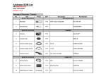
Arbitrator Hardware
Installation
Arbitrator SI Unit and Cables
AG-CPD15P
AJ-P2C016RG
P2 recorder (VPU)
16GB P2 Card
AG-CK10P
Camera
Camera Mount
Camera Cable Camera Cable
(Short)
(Long)
AG-CR12P
GPS Antenna
Power Cable
for P2 recorder
External GPIO
Trigger Cable
USB Extension
Cable
LAN Cable
USB/LAN Adaptor
(including a driver CD) (Crossing type)
OPTIONS
TDSS-900-PNA
AG-RCP30P
Digital Wireless
Mic Reciever &
Transmitter
In Car Mic
CN258IR-P
Receiver Cable
Control Panel
Control Panel
Cable
2nd Rear Camera
Arbitrator SI System Configuration
OPTION:
AG-RCP30P
Control Panel
Control Panel Cable
GPS Antenna
USB/LAN
Adaptor
Toughbook
(In car PC)
Front End
Application (SI)
USB Thumb
Drive*
In car mic
LAN Cable
AG-CR12P
Digital WMIC RX/TX
TDSS-900-PNA
USB Extension Cable
Digital RX/TX
P2 Recorder (Rear)
2nd WMIC Receiver/
Transmitter (Option)
AG-CPD15P
Power Cable
Camera Cable
2nd Rear Camera (Option)
AG-CK10P
CN258IR-P
*USB Thumb Drive needs to be provided by 3rd vender
In car Camera
GPIO Trigger Cable
8 Trigger Inputs
(Siren/Light
Bar/Brake/WMIC etc)
Car Battery
12V/24V
P2 Recorder, Wireless MIC to Battery Connection (w/ VPU timer)
“RED” cable : Connect via 5A fuse (Not included in Arbitrator kit) to Battery (+)
“WHITE” cable : Connect via 5A fuse (Not included in Arbitrator kit) to ACC line or switch.
Don’t connect to Battery (+)
“BLACK” cable: Connect to Battery ( - )
P2 Recorder
Fuse
5A
RED
power
(+)
RED
■
Clock
Ignition etc.
Fuse
5A
Car Battery
12V/24V
(-)
power
Recording engine
signal(SA)
■
WHITE
WHITE
■
BLACK to
Battery-
1A fuse is included
In RX Cable
BLACK to
Battery-
RED
Receiver (RX) Cable
WMIC Receiver (RX)
P2 Recorder, Wireless MIC to Battery Connection (w/ Charge Guard)
“RED” cable : Connect via 5A fuse (Not included in Arbitrator kit) to Battery (+)
“WHITE” cable : Connect via 5A fuse (Not included in Arbitrator kit) to ACC line or to the
Charge Guard. Don’t connect to Battery (+)
“BLACK” cable: Connect to Battery ( - )
P2 Recorder
RED
Fuse
5A
power
(+)
RED
■
Clock
Fuse
5A
Car Battery
12V/24V
(-)
Charge
Guard
power
Recording engine
signal(SA)
■
WHITE
WHITE
■
BLACK to
Battery-
1A fuse is included
In RX Cable
BLACK to
Battery-
RED
Receiver (RX) Cable
WMIC Receiver (RX)
AG-CR12P
Cables for P2 Recorder
Power Cable
for P2 recorder
GPIO/Serial Connector
External GPIO
Trigger Cable
RS-232C
GPIO Trigger Cable
USB
Extension Cable
Network Cables(AG-CR11P), Control Panel Cable, Camera Cable
USB/LAN Adaptor
(including a driver CD)
Control Panel
Cable
(included in AG-RCP30P)
Camera Cable
(included in AG-CK10P)
LAN Cable
(Crossover type)
External GPIO Trigger Cable/Power Cable Connection
P2 Recorder
(Rear)
Power Cable
Black (GND: - ): Connect to the negative ( - ) terminal of
the battery
Red (BATT: +): Connect via a 5A fuse to a power supply
that is constantly on, regardless of ignition key ON/OFF status
External GPIO
Trigger Cable
Others: Input signal lines
White (SIGNAL) : Connect the signal line via 5A fuse
to the ACC line or to the output terminal of a timer box
White: REC Tally output line
Black: Connect to the NEGATIVE(
NEGATIVE(-) terminal of the battery
Gray: Input signal or Speed pulse signal
RS-232C: Connect to equipment with serial connectors
External GPIO Trigger
See “Cable Color” as below chart
External GPIO Trigger Cable
(supplied)
Pin #
Signal
Remark
Cable Color
Trigger Name (Example)
9
GND
GPIO
Black
Black MUST be grounded (To ground at Negative battery terminal)
10
GPIO1
In
Brown
Wireless Mic
11
GPIO2
In
Red
Light Bar
12
GPIO3
In
Orange
Brake Indicator
13
GPIO4
In
Yellow
Siren Indicator
21
GPIO5
In
Green
Gun Lock
22
GPIO6
In
Blue
Other
23
GPIO7
In
Purple
Other
24
GPIO8
In
Gray
Speed Sensor with pulse table setting only
25
GPIO9
Out
White
For Low Voltage Output only (LED or Relay)
*GPIO for Wireless Mic, Light bar, Siren etc.. as above example.
*Serial (RS-232C, Pin number either of 2-8 & 20) for Rader Gun etc
Digital Wireless Mic Receiver Connection
Digital Wireless Mic
Receiver & Transmitter
Receiver (RX)
RX Cable Power (RED)
To Battery via Timer Box
RX Cable Power GND (Black)
Car Battery
12V/24V
To Battery (-)
To
Receiver
Jack
RX Cable Trigger REC (Yellow)
To either of GPIO 1 to 8
(Ex. GPIO1 Brown)
RX Cable GND (Black)
To Battery(-)
Receiver (RX)
Cable
To
Audio In 1
(RCA PIN)
In Car Mic
To
In Car Mic
2nd Wireless Mic
Receiver (optional)
To
Audio In 2
P2 Recorder
(Rear)
External GPIO
Trigger Cable
2nd Rear Camera (Option:CN258IR-P) Connection
2nd Camera
(Front)
2nd Camera
Cable
White to Battery (+)
via Timer Box
Black to Battery (-)
Car Battery
12V/24V
Yellow to Camera 2
P2 Recorder
(Rear)
Control Panel (Option: AG-RCP30P) Connection
Control Panel
Control Panel Cable
To
Control Panel
P2 Recorder (Rear)
Control Panel (Option: AG-RCP30P) Buttons
Book
Mark
Auto
Zoom
1) Lock Lamp
LCD
Screen
Lock except “REC”, “Menu”,
“Control Panel ON/OFF”,
“Return” Button while lights on
2) Ready Lamp
3) Busy Lamp
Backlight
Compensation
Cursor Button
T: Zoom In
W: Zoom Out
Return
To go back to previous
menu or setting
Menu
REC/STOP
Lamp
Skip
(Back/Forward)
REC
Button
Live/Archive
Switching Button
STOP
Button
Control Panel
ON/OFF
Audio 2 Mute
Button/Lamp
Mute Audio 2 and lamp lights
on by pushing this button.
No recording while muting
(lights on)
IR Mode
(Auto/ON/OFF)
Camera
Select
(Camera1/2))
Volume
Control
Brightness
Control
Before use, Format 16G P2 card by SI
Formatting 16G P2 card is mandatory at the first time usage.
When modified (copy, delete, move etc) folders in P2 Card, please format the card.
(If you copy the folders/files from 5 slot P2 drive or PC PCMCIA to PC HDD, please format the card.)
The format of 16G P2 card is available by Control Panel, 5 slot P2 drive and PC PCMCIA slot.
Note that 16GB P2 card limit the number of files that can be recorded per below chart.
# of
recording days
62 days
# of maximum recording files per day
With Bookmark
Without Bookmark
340 files
508 files
<How to format by SI?>
•
•
Insert new 16GB P2 cards to P2 Recorder (VPU)
Go to “Config” by SI menu and select “Operations”.
Press “Format” and then select “Yes”
(c) Press “Format” and select “Yes”.
Then, “Format finished successfully” message
will be appeared when the format is completed.
Before use, Format 16G P2 card by Control Panel
(Option: AG-RCP30P)
Formatting 16G P2 card is mandatory at the first time usage.
When modified (copy, delete, move etc) folders in P2 Card, please format the card.
(If you copy the folders/files from 5 slot P2 drive or PC PCMCIA to PC HDD, please format the card.)
The format of 16G P2 card is available by Control Panel, 5 slot P2 drive and PC PCMCIA slot.
Note that 16GB P2 card limit the number of files that can be recorded per below chart.
# of
recording days
62 days
# of maximum recording files per day
With Bookmark
Without Bookmark
340 files
508 files
<How to format 16GB P2 card by Control Panel?>
•
•
•
Insert new 16GB P2 cards to P2 Recorder (VPU)
By Control Panel Menu, go to “Setup/Info”, “Admin (page 2/2)”, “File Management” and select “Format”
Press “Format” when “Format all P2 cards!!!” message is appeared.
Then, you will see “All cards are formatted” message when the format is completed.
[File Management]
[Setup/Info]
[Top Menu]
[Admin] Page 2/2
16GB P2 Card Format by Products /
Combination with Windows version
Format by
How to format?
SI
(FE Application)
By SI Menu, go to “Config”-”Operations”-”Format”.
Control Panel
By Control Panel Menu, go to “Setup Info”-”Admin”-”File Management””Format”
PC PCMCIA slot
(Windows)
Select the removable disc drive in PC that inserted P2 card. Right click
on that drive and select “format”
5 slot P2 Drive
(AJ-PCD20P)
Select the removable disc drive in PC that inserted P2 card. Right click
on that drive and select “format”
P2 Store
(AJ-PCS060G)
Press “Format P2C” button on the unit
Vista
XP
Pro SP2
2000
Pro SP4 + Hot Fix
Server
2003
PCMCIA slot (Card Bus) in PC
Y
Y
N
N
5 slot P2 Drive (AJ-PCD20P)
through USB
Y
Y
Y
N
5 slot P2 Drive (AJ-PCD20P)
though IEEE1394
Y
Y
N
N
P2 Store (AJ-PCS060G)
through USB
Y
Y
Y
N
For the users who need Win2000 SP4+Hot Fix, please contact 1-800-LAPTOP5 (1-800-527-8675) to obtain the copy of the file.
Appendix
External GPIO Trigger (External LED)
If the officer would like to see the REC status from inside of car
additionally, it is possible to set up the LED light connecting to
GPIO.
Siren Detector Cable (Option)
Siren Detector Cable (Option)
Specification:
Contact Information:
LIND Electronics
www.lindelectronics.com
Toll Free 1-800-659-5956
G-Force Sensor (Option) Connection
Black (GND: - ):
Connect to the negative ( - ) terminal
of the battery
Red (BATT: +):
Connect to a power supply that is
constantly on, regardless of ignition
key ON/OFF status
<Power Cable>
<Trigger Cable>
Connect each cable to the VPU
trigger cable to record by the trigger
G-Force Sensor (Option) Trigger
Pin #
Description
Cable Color
1
FLIP Out
White
2
RIGHT Out
Orange
3
LEFT Out
Blue
4
REAR Out
Red
5
FRONT Out
Brown
6
REC Out
Green
7
GND
Yellow
8
GND
Black
9
GND
Gray
If you have 5 trigger inputs available for VPU, connect
Pin#1-5 with VPU trigger cable so that VPU can start
recording by the impact from any 8 directions with
indication on screen of SI and/or Control Panel.
If you have only 1 trigger input available for VPU, connect
to Pin #6 to start recording by the trigger regardless of
which direction the impact comes from.