1
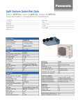
Split System Submittal Data
System: 26PET1U6 Indoor: S-26PT1U6 Outdoor: U-26PE1U6
Single Split System - Ceiling-Suspended Heat Pumps
Job Name:
Location:
Engineer:
Submitted to:
Submitted by:
Reference:
Approval:
Date:
Construction:
Unit#:
Drawing#:
General Data
Power (V/P/Hz)
Circuit Ampacity (A)
Fuse Size, Max.(A)
230/208/1/60
15-30 Indoor-Outdoor
15-30 Indoor-Outdoor
Compressor
No. Used
R.L. Amps - L.R. (A)
DC Rotary Inverter
1
12.9 - 17.5
Outdoor Unit
Fan type
Dia & Length (in.) - No. Speeds
Type Drive - No. Speeds
No. Poles (RPM)
No. Motors (W)
CFM (High)
F.L. Amps (A)
Propeller
18-7/64-1
DC Motor
8 - 800
1 - 90
1765
13.8
Coil Type
Fin Type - Pipe Type
Rows - F.P.I.
Face Area (sq.ft.)
Tube Size (in)
Aluminum Fin & Copper Pipe
Slit Plate - Inner Rifled
1 - 15.9
7.26
3/8"
Indoor Unit
Fan type
Dia & Length (in.) - No. Speeds
No. Speeds
No. Poles (RPM, High)
No. Motors (W)
CFM (HI/Med/Lo)
Indoor Sound Rating (Hi) (dB-A)
F.L. Amps (A)
Centrifugal
5-1/8-4
3 & Auto
4 - 1179
1 - 31
550/490/460
39
0.5
Coil Type
Fin Type - Pipe Type
Rows - F.P.I.
Face Area (sq.ft.)
Tube Size (in)
Drain Connection Size (in.)
Aluminum Plate Fin & Copper Tube
Slit Plate - Inner Rifled
3 - 14.9
1.81
9/32"
1-1/4"
Refrigerant
Lbs. - R410a
Control
Connection
Line Length, Max (ft.)
Line Difference, Max (ft.)
Line Size (in. O.D. Discharge)
Line Size (in. O.D. Suction)
R410A
4.19
Electric Expansion Valve
Flare
165
50 (outdoor lower),
100 (outdoor higher)
3/8"
5/8"
Dimensions (HxWxD)
Indoor Unit (Crated) (in.)
Indoor Unit (Uncrated) (in.)
Outdoor Unit (Crated) (in.)
Outdoor Unit (Uncrated) (in.)
9-7/16 x 54-19/32 x 31-1/16
7-17/16 x 51-3/16 x 26-3/8
34-31/32 x 39-31/32 x 16-3/32
30-23/32 x 37 x 13 3/8
Weight (lbs.)
(Indoor) Net
(Indoor) Shipping
(Outdoor) Net
(Outdoor) Shipping
64
75
128
148
(Indoor) Shipping Volume (cu.ft.)
(Outdoor) Shipping Volume (cu.ft.)
8.9
13
Performance Data @ ARI Standard Conditions (230V)
Option
Cooling
Total Capacity (BTU/H)
Sensible Capacity (BTU/H)
Latent Capacity (BTU/H)
SEER
Dehumidification (Pints/H)
Amps (A)
Power Inputs (W)
Outdoor Sound Rating (dB-A)
Refrigerant Line Set
Fresh Air Intake
Airduct Extension
Indoor Frame Extension
Condensate Drain Pump
Non-Removeable Remo-con
Bracket
Heating
Total Capacity (BTU/H)
HSPF
Amps (A)
Max Amps (A)
Power Inputs (W)
Back-up Strip Heather (KW)
Outdoor Sound Rating (dB-A) High
24,400 (9,500 - 24,400)
14,330
10,070
14.5
7.7
15.6/17.3
2,880/2,880
49
30,800 (8,000 - 30,800)
10.3
16.4/18.1
16.4/18.1
3,000/3,000
0.00/0.00
49
Features
Controls
Remote Controller
Temperature Control
Timer
Night Setback
Air Louver, Horizontal
Air Louver, Vertical
Power Failure Automatic
Changeover
Heating/Cooling Automatic
Changeover
Self-Diagnosis
Air Filter
Panasonic North America
Air Conditioning Division
1690 Roberts Blvd., NW, Suite 110
Kennesaw, GA 30144
us.panasonic.com/aircon
Microprocessor
LCD Wired Type, Temp. Sensor
Built in
IC Thermostat
72 Hr. On/Off
Built-In
Manual
Automatic
Built-In
Built-In
Built-In
Washable, Anti-Mold
Available
Knock-out
N/A
N/A
Available
Available
Operating Range
Indoor Air Intake Temp
Outdoor Air Intake Temp
Cooling (Max)
Cooling (Min)
Heating (Max)
Heating (Min)
95F DB/71F WB
67 DB/57F WB
80F DB/67F WB
-DB/-WB
115F DB
0F DB
75F DB/65F WB
5F DB
1-4 Dimensional data
Indoor unit : Ceiling Type
26 Type
1. Specifications
intake
1-3/32
6-5/16
1
1-41
50-13/32
26-3/8
8-7/16
Front
(Service space)
9-7/8
Front
(Service space)
9-7/8
1-4 Dimensional Data
3-1/2
5-25/32
Outdoor Dimensions
7-7/32
Dimension : inch
4-1/16
5-25/32
Drain connection
Drain connection for left side
Refrigerant liquid line (3/8") Flare connection
Refrigerant gas line (5/8") Flare connection
Hole for rear side refrigerant tubing
Hole for through-the-wall refrigerant tubing (ø3-15/16" hole)
Hole for fresh air intake (Knockout hole)
Hole for right side refrigerant tubing (Knockout hole)
Hole for left side drain connection (Knockout hole)
Hole for power supply (Conduit size 1/2")
Infrared rays receiver for wireless remote controller
Cutting position for fresh air intake
7-7/32
Dimension : inch
Drain connection
Drain connection for left side
Refrigerant liquid line (3/8") Flare connection
Refrigerant gas line (5/8") Flare connection
Hole for rear side refrigerant tubing
Hole for through-the-wall refrigerant tubing (ø3-15/16" hole)
Hole for fresh air intake (Knockout hole)
Hole for right side refrigerant tubing (Knockout hole)
Hole for left side drain connection (Knockout hole)
Hole for power supply (Conduit size 1/2")
Infrared rays receiver for wireless remote controller
Cutting position for fresh air intake
1919_THS_I
1-41
1919_THS_I
SM830203-01_PAC-i_US-letter.indb41 41
2012/01
1-41
Panasonic North America
Air Conditioning Division
1690 Roberts Blvd., NW, Suite 110
Kennesaw, GA 30144
us.panasonic.com/aircon
2012/01/19 22:39:24
4-1/16
(B) Outdoor Unit: U-26PE1U6, U-26PS1U6
U-36PE1U6, U-36PS1U6
3-1/2
5-25/32
8-7/16
3-3/4
2 ft. or more
10
or more
7-15/32
10
or more
(Service space)
51-3/16
5-25/32
51-3/16
10
Air outlet or more
3-3/4
9-7/8
26-3/8
Air intake
S-letter.indb41 41
1919_THS_I
1-3/8
1-3/8
50-13/32
(Service space)
1-3/8
(B) Outdoor Unit: U-26PE1U6, U-26PS1U6
U-36PE1U6,
U-36PS1U6
48-7/16 (Suspension
bolt hole pitch)
SM830203-01_PAC-i_US-letter.indb41 41
10
Air outlet or more
Hole for wall-through piping (View from front)
7-15/32
48-7/16 (Suspension bolt hole pitch)
6-5/16
1-4 Dimensional Data
6-5/16
6-5/16
12-19/32
(Suspension bolt hole pitch)
1-3/32
12-19/32
Hole for wall-through piping (View from front)
2-25/32
5-9/16
3-9/32
Drain connection for left side
Refrigerant liquid line (3/8") Flare connection
Refrigerant gas line (5/8") Flare connection
Hole for rear side refrigerant tubing
Hole for through-the-wall refrigerant tubing (ø3-15/16" hole)
Hole for fresh air intake (Knockout hole)
Hole for right side refrigerant tubing (Knockout hole)
Hole for left
side drain connection
5-3/16
2-25/32 (Knockout hole)
Hole for power supply (Conduit size 1/2")
Infrared rays receiver for wireless remote controller
Cutting position for fresh air intake
(Suspension bolt hole pitch)
5-9/16
3-9/32
5-3/16
5-3/4
Dimension :4-9/16
inch
4-23/32
5-25/32
5-3/4
4-9/16
11-1/32
Holes in the rear side
(View
from front)
Drain
connection
4-23/32
3-15/16
11-1/32
2-17/32
5-9/32
11-1/32
3-3/8
3-15/16
12-7/32
1-3/8
5-25/32
3-3/32
3-15/16
Holes in the rear side (View from front)
2 ft. or more
-7/8
12-7/32
4-1/16
11-1/32
5-25/32
7-7/32
6-3/32
3-3/8
3-15/16
5-25/32
3-3/32
6-3/32
3-1/2
5-25/32
Indoor Dimensions
ndoor unit : Ceiling Type
26 Type
2-17/32
5-9/32
Dimensional data
2012/01/19 22:39:24