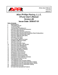
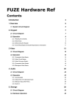
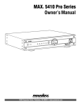
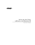
1
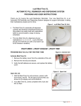
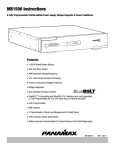
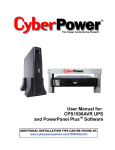
MAX Home Cinema UPS
Owner’s Manual
®
Pure Sine Wave
al Load Control
Intelligent Critic
POWER ON
TEST
POWER
BATTERY LEVEL
LOAD LEVEL
LINE FAULT
E
UNSAFE VOLTAG
BATTERY MODE
AVR MODE
M1500-UPS
1690 Corporate Circle, Petaluma, CA 94954 • www.panamax.com
MAX® Home Cine
ma UPS
Table of Contents
Important Safety Instructions.............................................................pg. 1
Battery Features........................................................................pgs. 10, 11
Installing Your UPS.............................................................................pg. 2
Diagnostics.......................................................................................pg. 11
Basic Operation.............................................................................pgs. 2, 3
Troubleshooting................................................................................pg. 12
Advanced Operation......................................................................pgs. 4, 5
Technical Specifications....................................................................pg. 12
Home Cinema Power Control Software Installation Instructions...pgs. 5, 6
RS232 Communications Protocol & Command Set.....pgs. 13, 14, 15, 16
Home Cinema Power Control Software Instructions............pgs. 7, 8, 9, 10
FCC Notice and Warranties..............................................................Pg. 17
Before You Begin
UNPACKING
Inspect the UPS upon receipt. In addition to this manual the box should contain the following:
2. Power Cord
1. UPS Unit
3. Phone Cord
Pure Sine Wave
Load Control
Intelligent Critical
POWER ON
TEST
POWER
BATTERY LEVEL
LINE FAULT
LOAD LEVEL
UNSAFE VOLTAGE
BATTERY MODE
AVR MODE
5. Rack Mounting Kit
MAX® Home Cinema
UPS
6. Home Cinema
Power Control
Software
Please verify that you have received all these items. If not, contact Panamax.
PANAMAX, the Panamax logo and MAX are registered US trademarks of Panamax.
Protect or Disconnect, and SignalPerfect are trademarks of PANAMAX.
SIDACtor is a registered US trademark of Teccor Electronics, Inc. TiVo is a trademark of TiVo, Inc.
© 2005 PANAMAX CORP. All Rights Reserved.
4. DB 9 Serial Cable
Important Safety Instructions
This manual contains important instructions that should be followed during installation and maintenance of the UPS and batteries.
Please read and follow all instructions carefully during installation and operation of the unit. Read this manual thoroughly before
attempting to unpack, install, or operate.
CAUTION! The UPS must be connected to an AC power outlet
with fuse or circuit breaker protection.
CAUTION! To reduce the risk of electric shock, do not remove
the cover, except to service the battery. No user serviceable parts
inside, except for the battery.
DO NOT plug the machine into an outlet that is not grounded.
If you need to de-energize this equipment, turn off and unplug
the UPS.
CAUTION! To avoid electrical shock, turn off the unit and unplug
it from the AC power source before servicing the battery or
installing a component.
CAUTION! DO NOT USE FOR MEDICAL OR LIFE SUPPORT EQUIPMENT! Panamax does not sell products for life support or medical applications. DO NOT use in any circumstance that would
affect operation or safety of any life support equipment, with any
medical applications, or patient care.
CAUTION! DO NOT USE WITH OR NEAR AQUARIUMS! To reduce
the risk of fire, do not use with or near aquariums. Condensation
from the aquarium can come in contact with metal current contacts and cause the machine to short out.
CAUTION! The battery can energize hazardous live parts inside
even when the AC input power is disconnected.
CAUTION! To prevent the risk of fire or electric shock install in a
temperature and humidity controlled indoor area, free of conductive contaminants. (Please see specifications for acceptable
temperature and humidity range).
Pure Sine Wave
al Load Control
Intelligent Critic
POWER ON
TEST
POWER
BATTERY LEVEL
LOAD LEVEL
LINE FAULT
E
UNSAFE VOLTAG
BATTERY MODE
ma UPS
AVR MODE
MAX® Home Cine
MODEL # M1500-UPS
CAUTION! The 2 silver handles on the battery
access panel are for removing the panel only.
NOT FOR LIFTING PRODUCT.
USA & Canada (800) 472-5555 • (707) 283-5900 • Fax (707) 283-5901
1
Installing Your UPS
HARDWARE INSTALLATION GUIDE
1. Your new UPS may be used immediately upon receipt.
However, recharging the battery for at least four hours is recommended to insure that the battery’s maximum charge capacity
is achieved. Charge loss may occur during shipping and storage.
To recharge the battery, simply leave the unit plugged into an AC
outlet. The unit will charge in both the ON as well as the OFF
position. If you wish to use the software, connect the enclosed
serial interface cable to the serial port on the UPS and an open
serial port on the computer.
4. Plug the UPS into a 2 pole, 3 wire grounded receptacle (wall
outlet). Make sure the wall branch outlet is protected by a fuse or
circuit breaker and does not service equipment with large electrical demands (e. g. refrigerator, copier, etc.) Avoid using extension cords. If used, the extension cord must be rated for 15
Amps.
2. With the UPS unit OFF and unplugged, plug your home theater equipment into the unit’s rear panel AC outlets. DO NOT plug
a laser printer, copier, space heater, vacuum cleaner, paper shredder or other large electrical device into the UPS. The power
demands of these devices will overload and possibly damage
the unit.
6. The rear panel circuit breakers will open and power to the connected equipment will be turned OFF if an overload is detected.
To correct this, turn the UPS off, unplug at least one piece of
equipment, wait 10 seconds, check to make sure that the circuit
breakers are reset, and turn the unit on.
3. To protect a telephone modem line (DVR or Satellite TV
receiver) or network cable, connect a telephone cable or network
cable from the wall jack outlet to the IN jack of the UPS. Then
connect a telephone cable or network cable from the OUT jack
on the UPS to the equipment’s telephone jack or network device.
Note: This unit provides both telephone and LAN protection on
one set of RJ-11/45 jacks. The telephone cirLAN
TEL cuit uses pins 4 & 5 while the LAN circuit uses
pins 1, 2, 3 & 6. Adapters or custom cables
1 2 3 4 5 6 7 8 (not included) must be used when utilizing
RJ-45
both protection circuits at the same time.
5. Press the power switch to turn the UPS on. The Power ON
indicator light will illuminate.
7. The UPS will automatically charge the battery whenever it is
plugged into an AC outlet,
8. To maintain optimal battery charge, leave the UPS plugged
into an AC outlet at all times.
9. To store your UPS for an extended period, cover it and store
with the battery fully charged. Recharge the battery every three
months to insure battery life.
Basic Operation
FRONT PANEL DESCRIPTION
Power Switch
Test Switch
Removable Access Panel
Press the power
button to turn the
UPS ON or OFF.
This UPS performs a self-test automatically when powered on. The test switch allows
you to test the system at any time. When the UPS passes the test, it returns to online operation. If the UPS fails the self-test, please recharge the battery for 4 hours
and perform another self-test. If it fails after recharging the battery, please replace
the battery. In battery mode, you can press this button to silence an audible alarm.
Easy to remove for battery access and
replacement.
POWER
DO NOT lift product with handles.
They are for panel removal only.
POWER ON
TEST
BATTERY LEVEL
LINE FAULT
UNSAFE VOLTAGE
LOAD LEVEL
Pure Sine Wave
Intelligent Critical Load Control
BATTERY MODE
AVR MODE
MAX® Home Cinema UPS
2
USA & Canada (800) 472-5555 • (707) 283-5900 • Fax (707) 283-5901
Basic Operation (continued)
FRONT PANEL DISPLAY LED DESCRIPTIONS
Power On Indicator
Line Fault Indicator
Unsafe Voltage Indicator
This LED is illuminated when
the utility condition is normal
and the UPS outlets are providing clean, protected power.
This LED will illuminate to warn the user that a
wiring problem such as a bad/missing ground or
reversed wiring exists within the AC receptacle.
If illuminated, disconnect all equipment and contact
an electrician to insure outlet is properly wired.
This LED will illuminate to inform the user that
an unsafe line voltage is present and that the
UPS has switched to battery power. This could
be either an over-voltage or under-voltage.
POWER ON
Load Level Indicator
Battery Level Indicator
LINE FAULT
BATTERY LEVEL
This is a visual indication of the
battery charge. If battery capacity is under 25%, no indicator
LED will illuminate and UPS
starts beeping (if the audible
alarm is enabled).
This is a visual indication of the
UPS load.
LOAD LEVEL
UNSAFE VOLTAGE
The 1st arrow will illuminate when
the load is above 25%, the 2nd
above 50% and the 3rd above
75%. The 4th arrow will flash
when the load is between 85%
and 100%.
1 2 3 4
BATTERY MODE
AVR MODE
Battery Mode Indicator
AVR Indicator
This illuminates during utility failure or
an unsafe voltage condition, indicating
that the battery is supplying power to
the connected equipment.
This indicates that the UPS is operating in automatic voltage regulation mode. When the led is illuminated continuously, it indicates an input over-voltage and the UPS unit reduces (bucks) the voltage to the normal operating range. When the led is flashing, it indicates that the input line voltage
is low and that the UPS is increasing (boosts) input voltage to the normal range.
REAR PANEL DESCRIPTION
Non-Critical-Load Outlets
Critical Load Outlets
Four battery powered, surge
protected and AVR outlets for
connected equipment insures
temporary uninterrupted operation of connected equipment
during a power failure.
Two battery powered, surge
protected and AVR outlets for
critical-load equipment
insures temporary uninterrupted operation of connected
equipment during a power
failure.
AC Power
Cord Input
Receptacle
IR Control Section
Learning Control Switches – Push to program or test the IR function
IR Detector Window – Receives the IR signal to be learned
Indicator LED’s – Indicates learning status
Output Delay Switches – Set the desired time delay between a power failure and
when the IR signals are sent to the connected equipment
IR Output Jacks – Standard 1/8” (3.5mm) mono jack for connection to an IR
flasher (IR flashers not included)
OUTPUT DELAY
NON CRITICAL
LOAD OUTLET
BANK
3
30 SEC.
MAIN
1
2
CRITICAL
LOAD
OUTLET
BANK
IR DETECTOR
IR1
5 MIN.
IR2
AC INPUT
IR OUTPUT
PROGRAM / TEST
IN
OUT
RS232 CONTROL
Circuit Breakers for
Overload Protection
Resettable circuit
breakers provide
optimal overload
protection.
RS232 Serial Communication Port
RJ11/RJ45 Jacks
The serial port allows connection and communication between
the UPS and a HTPC (home theater personal computer) or home
automation system. If used temporarily during setup (with the
included software), it allows the installer to program a number of
variables including the Critical Load Battery Threshold. See the
software documentation for more information.
Ports protect standard telephone line,
modem, or network
cable.
USA & Canada (800) 472-5555 • (707) 283-5900 • Fax (707) 283-5901
3
Advanced Operation
Audio/Video components such as Digital Video Recorders, DLP
projectors and any component with volatile memory can benefit
from connection to a UPS. The Panamax M1500-UPS takes this
to the next level with a number of features designed specifically
for the home theater.
Critical Load Function
One of the user programmable settings in the Home Cinema
Power Control software is the Low Battery NCL Shutoff threshold. This sets the battery capacity level at the point where the
non-critical load outlets are turned off and all remaining battery
power is reserved for equipment plugged into the 2 critical load
outlets. This value is stored internally by the UPS and is not
dependent on having the software running on a computer.
Learning IR Control
The learning IR function lets you program the UPS to send
standby or shut-down commands to components such as DLP
ceiling projectors. If the power fails, the projector’s lamps are
turned off while the UPS continues providing battery power to
the projector’s cooling fan. Proper shutdown is ensured and
expensive lamps are protected from damage.
Note: This function should only be used with discrete IR codes.
Programming an On/Off toggle command could result in the
equipment being turned ON during a power failure!
IR LED Color & Status
LED COLOR
Off
Green, solid
Green, flashing
Red, flashing
STATUS
Idle
Waiting to receive IR signal
IR signal sampled
Failed to learn IR signal
To program IR output:
1. Press and hold the IR1 button for approximately 2 seconds.
2. When the IR1 LED turns solid GREEN, release the button
(after approx. 2 seconds)
3. Point the remote control at the detector window and quickly
press and release the appropriate button on the remote control.
If no signal is received within 10 seconds, the programming
mode is cancelled, the IR1 LED turns off and you will have to
start over.
4. The IR1 LED flashes GREEN if the IR signal is sampled and
stored in memory.
IR Power Failure Operation
The UPS can learn two IR commands. The learned commands
will be transmitted on both output jacks so you have the ability to
control 2 different pieces of equipment or use a 2-step macro for
one component.
5. The IR1 LED will flash RED if the IR signal was not learned.
Start over at Step 1.
The IR Output Delay switches provide the ability to “ridethrough” brief power outages without sending a shut-down signal to the connected device. You have a choice of a 30 second
or 5 minute delay.
To clear IR programming:
1. Press and hold the appropriate IR button, release after 2 sec.
1. After a power failure and the selected delay, the IR codes will
be sent to both outputs. The IR LED’s will flash once per second
during the delay time and will stop flashing after the IR code is
output.
3. Press the button again. The IR code will be erased from
memory and the LED will turn off.
2. If the delay settings are the same for both IR1 and IR2, the
IR2 code will be sent to both outputs 2 seconds after IR1.
3. The IR commands will also be transmitted immediately after
the battery charge falls below the critical load battery threshold.
This ensures that equipment will be shutdown properly if the
UPS’s load level is extremely high and the backup time would
be less than the 5 minute ride-through delay.
4. There is no IR output after the power is restored to the
system.
4
6. Repeat steps 1-5 for IR2.
2. The IR LED turns solid Green
IR Output Test
1. An IR flasher must be connected to the UPS and in line-ofsight to the IR receiver window of the equipment to be controlled
in order to verify that the code was learned correctly.
2. Make sure that the component to be controlled is turned ON.
3. Press and release the IRx button. The code for IRx will be
transmitted on both IR1 and IR2 outputs.
4. If you are testing a 2-step macro, be sure to press the second
IR button to transmit that code.
USA & Canada (800) 472-5555 • (707) 283-5900 • Fax (707) 283-5901
Advanced Operation (continued)
5. If the learning process was successful, the controlled equipment should accept the IR command and turn off or go into
standby mode.
6. Reprogram the IR command if the controlled equipment does
not respond.
a. Be sure that the batteries in the “teaching remote” are fresh
and do not need to be replaced.
b. If “press & release” (Step 3 in Programming) doesn’t work,
try “press & hold” on the remote control button being taught to
the UPS.
RS232 Control with Open Protocol
The RS232 serial interface can be used in the following ways:
1. Initial system setup. An installer can use a notebook computer to set the variables within the Home Cinema Power Control
software. Once the setup is completed, the notebook computer
can be disconnected. All settings are stored in the UPS.
2. Connection to a Home Theater Personal Computer (HTPC).
Functionality is very similar to a standard UPS with a PC.
The UPS can provide continued power to the HTPC to maintain
recording capabilities if it is being used as a digital video
recorder. It is also capable of saving open documents and
shutting down the HTPC during extended power failures.
This requires a permanent RS232 connection to the HTPC
and having the Home Cinema Power Control software running
in the background on the HTPC.
3. Integration with home automation systems like AMX and
Crestron. The serial communications command set and protocol
is open and is published later in this manual. This information
can be used by the automation system programmer for both UPS
control by the automation system and reporting of power events
by the UPS to the automation system.
Home Cinema Power Control Software
The M1500-UPS has one rear-panel serial port that provides the
ability to program special functions, safely shutdown a home theater PC (HTPC) or integrate the UPS with home automation systems.
Use of the Panamax software is optional. The communications
protocol is “open”; a programmer can write their own control
program or integrate the UPS’s programming/control functions
into home automation software if desired. The UPS will provide surge suppression, automatic voltage regulation and battery backup without the software. Automatic shutdown of an
HTPC requires the use of the software.
7. Plug the UPS into an AC outlet, turn the UPS on and start your
computer.
Software Installation
11. Once the software has finished installing, remove the disk
and restart your computer.
8. Windows will recognize your UPS as “New Hardware”.
9. Insert the software disk into the computer’s drive. The installation program should start automatically. If the installation
program does not start automatically, open it manually with
the Window’s “Run” command.
10. Follow the on-screen instructions.
For Windows XP (Home and Professional)
1. Click on Start and then click on Control Panel.
2. Double-click on Power Options then click on the UPS tab.
3. Set the manufacturer to none.
4. Exit to the desktop and shutdown your computer.
5. Turn the UPS off and unplug it.
6. Connect the serial interface cable to the UPS and an open
serial port on the back of the computer. (Note: You must use
the serial cable that was supplied with the unit).
For Windows 95/98/Me
1. Turn off your UPS.
2. Connect the Serial Cable to your UPS and the open serial port
on the rear panel of the computer. (Note: You must use the serial
cable that was supplied with the unit).
3. Plug the UPS into an AC outlet, turn the UPS on and then start
your computer.
4. Follow the instructions below for your PC’s operating system.
USA & Canada (800) 472-5555 • (707) 283-5900 • Fax (707) 283-5901
5
Home Cinema Power Control Software (continued)
5. Windows will recognize your UPS as “New Hardware”.
6. Insert the software disk into the computer’s drive. The installation program should start automatically. If the installation program does not start automatically, open it manually with the
Window’s “Run” command.
For Windows NT 4.0
1. Click on Start, point to Settings then click Control Panel.
2. Double-click on the UPS Icon.
3.. Remove the check mark from the box labeled UPS is installed
on.
7. Follow the on-screen instructions.
4. Click OK.
8. Once the software is installed, remove the disk and restart
your computer.
5. Acknowledge the message that the UPS is in an unknown
state.
For Windows 2000
1. Click on Start, point to Settings then click Control Panel.
6. Exit to the desktop.
2. Double-click on Power Options.
7. Shutdown your computer.
3. On the UPS Tab, click Select.
8. Turn the UPS off and unplug it.
4. In the UPS Selection Dialog Box, under Manufacturers,
click None.
9. Connect the serial interface cable to the UPS and an open serial port on the back of the computer. (Note: You must use the
serial cable that was supplied with the unit).
5. Exit to the desktop.
6. Shutdown the computer.
10. Plug the UPS into an AC outlet, turn the UPS on and then
start your computer.
7. Turn the UPS off and unplug it.
11. Click on Start, point to Settings then click Control Panel.
8. Connect the serial interface cable to the UPS and an open
serial port on the back of the computer. (Note: You must use
the serial cable that was supplied with the unit).
12. Double-click on Add/Remove Programs.
9. Plug the UPS into an AC outlet, turn the UPS on and start
your computer.
13. Insert the software disk into the computer’s drive. The
installation program should start automatically. If the installation
program does not start automatically, open it manually with the
Window’s “Run” command.
10. Windows will recognize your UPS as “New Hardware”.
14. Click Install.
11. Insert the software disk into the computer’s drive. The
installation program should start automatically. If the installation
program does not start automatically, open it manually with the
Window’s “Run” command.
15. Follow the on-screen instructions.
12. Follow the on-screen instructions.
When your computer restarts, the Home Cinema Power Control
software will appear on your screen for a few seconds, and then
minimize. It will appear as a blue and white battery icon located
in the system tray, near the clock.
13. Once the software has finished installing, remove the disk
and restart your computer.
6
16. Once the software is installed, remove the disk and restart
your computer.
USA & Canada (800) 472-5555 • (707) 283-5900 • Fax (707) 283-5901
Home Cinema Power Control Software Instructions
Overview
Panamax’s Home Cinema Power Control software is designed for
use with Windows 95, Windows 98, Windows Me, Windows NT,
Windows 2000 and Windows XP. It works in conjunction with
the UPS to provide full protection of home theater equipment
including digital video recorders, home theater PC’s (HTPC)
and video projectors/lamps.
This program may be used temporarily during the Initial system
setup. An installer can use a notebook computer to set the variables within the Home Cinema Power Control software. Once the
setup is completed, the notebook computer can be disconnected.
All settings are stored in the UPS.
The software can also be used to manage a Home Theater
Personal Computer (HTPC). Functionality is very similar to a
standard UPS with a PC. The UPS can provide continued power
to the HTPC to maintain recording capabilities if it is being used
as a digital video recorder. It is also capable of saving open documents and shutting down the HTPC during extended power failures. This requires a permanent RS232 connection to the HTPC
and having the Home Cinema Power Control software running in
the background on the HTPC. When a power failure occurs,
open files are saved under auto-assigned file names or existing
file names and the files closed. The computer and UPS are
automatically shutdown to conserve battery power. Files with
auto-assigned names will be saved under C:\PCTemp, where C
is the name of your main hard drive. Files that have previously
been saved will be saved in their original location.
There is also a Schedule feature that can automatically save and
close open files and then shutdown the computer and UPS at a
user specified date and time as well as re-start the computer at
a user specified date and time. Use of this feature is optional
and is not required for the power failure shutdown to occur.
MAIN MENU
1. Log Button: Opens the Event Log Window.
2. Power Button:
Closes the program window.
3. Minimize Button:
Minimize the program window.
4. Setup Button:
Opens the Setup Window.
5. Model: Shows the model
6. Schedule Button:
of UPS that is being used.
Click this button to access the
Schedule Window.
7. Status Bar: Displays messages
about the status of the software.
USA & Canada (800) 472-5555 • (707) 283-5900 • Fax (707) 283-5901
7
Home Cinema Power Control Software Instructions (continued)
MAIN WINDOW DESCRIPTIONS
1. Battery Level: Displays the
current charge on the battery. The
indicator will display a red color
when a power failure occurs.
2. Input Voltage: Shows the current input
voltage. The input normally appears in green, but
will turn red if the input voltage is lower than 85v
or higher than 150v.
3. Output Voltage: Shows the
output voltage of the UPS.
4. Load Level: Shows the % of capacity
that is currently being used. If the load level
exceeds 90%, the indicator will change to a
red color.
10. Frequency:
5. Temperature:
This indicator displays
the frequency of the
utility power.
Displays the internal operating temperature of the
unit. If the temperature
exceeds 158°F (70°C), the
indicator will change from
green to red.
9. Scheduled On:
The Home Cinema Power
Control software can be
scheduled to turn your
connected equipment on.
It can only be set when a
Scheduled Off is also set.
Scheduled On settings
that are set to occur within seven days will be displayed.
6. Scheduled Off:
8. Countdown:
For use with a Home Theater PC. When the program
detects that the utility voltage is below 88 volts or above 147 volts, the
countdown will begin. When the countdown reaches zero, the program will
save and close any open applications, and then shut down the operating
system in an intelligent and orderly manner.
SETUP MENU
12. Time between
power failure and
shutdown: For use with
1. Play voice:
Enables audible voice messages through your
computer speakers. A sound
card and speakers are required.
7. Approximate Backup Time:
Indicates the approximate
amount of backup time that is available, based upon the battery
capacity and the load on the system. This indicator can appear in red,
yellow, or green, depending upon the number of minutes available.
2. Alarm On: Toggles
the audible alarm on and off.
3. UPS Communication Media: Leave this on “Auto” for automatic detection or select the correct communications port from the dropdown list. The port assigned to the UPS needs to be used exclusively for
the UPS software.
4. OK:
Closes the
window and saves
changes.
an HTPC. This is the user
controllable delay between
when the power fails and
the software starts the
shutdown process. If
unchecked, the unit will
run on battery until the low
battery signal is received
(2 minutes of backup time
remaining) and then start
the shutdown process.
5. Cancel: Closes
the window without
saving changes.
6. Default:
Returns the software
to original factory
settings.
11. Time between
power failure and
initial warning:
7. Advanced:
Opens the Advanced
Setup Window.
Sets the time delay
between a power failure
and the first audible
alarm.
10. Delay between warning messages:
Sets the delay between the audible alarms (during a
power failure).
8
The program can be set
to automatically shutdown
the system at a user
specified time. Scheduled
Off settings that are set to
occur within seven days
will be displayed. When
combined with the
Scheduled On function,
connected equipment can
automatically be rebooted.
9. UPS Self-Test: Allows the user to test the
UPS without having to unplug the unit from the wall.
When Run is clicked, the UPS will switch to battery
power and the unit will beep.
8. About:
This button will display information about the software,
as well as contact information.
USA & Canada (800) 472-5555 • (707) 283-5900 • Fax (707) 283-5901
Home Cinema Power Control Software Instructions (continued)
ADVANCED SETUP MENU
1. Low Battery HTPC Shutoff: For use with a Home Theater PC.
Sets the low battery cutoff level. The user can slightly extend the UPS run
time by adjusting this setting. This setting must be higher than the Critical
Load Threshold if the HTPC is plugged into a non-critical load outlet.
2. Low Battery NCL Shutoff:
NCL stands for NonCritical Load. Sets the % of battery capacity at which all
remaining battery power is reserved for the equipment
plugged into the critical load outlet bank. Power to the 4
NCL outlets will be turned off at this point.
3. Cold Start:
When this is
enabled, the UPS can start in the
absence of AC power. To maximize
battery life, it is recommended to
keep this disabled.
9. High-Voltage
Failure: Sets the
4. OK: Closes
the windows and
saves changes.
upper level where the
UPS will cycle to battery.
This level can be adjusted
from 137V to 147V.
5. Cancel: Closes
the window without
saving changes.
8. Low-Voltage
Failure: Sets the lower
level where the UPS will
cycle to battery. This level
can be adjusted from 88V
to 97V.
6. Default:
Restores the settings
to the factory defaults.
7. Battery-mode
Output Voltage:
Sets the voltage that the
unit will output. This
level can be adjusted
from 110V to 130V when
running on battery.
SCHEDULE MENU - SPECIAL
1. Special
Setting: Allows
2. Weekly Setting: Allows you to
schedule a shutdown and start up based
upon the day of the week.
3. Turn Off: Select the day/date and time that
you want the computer system to shutdown. This is
optional and has no effect on whether your computer
will shut down during a power failure.
you to schedule a
one-time shutdown/startup.
4. OK: Closes the window. Please note: You
must click Add to add
the item to the schedule.
5. Cancel:
9. Turn On: Select
the day/date and time
that you want the computer system to restart.
Can only be used in
conjunction with a
scheduled shutdown.
8. Schedule
Display: Window
display of the
days/dates and times
of any scheduled
startups and shutdowns.
USA & Canada (800) 472-5555 • (707) 283-5900 • Fax (707) 283-5901
Closes
the window without
saving any schedules
even if one was added
to the Schedule Display
Window. Does not cancel previously applied
schedules.
6. Add:
Adds an
item to the schedule.
7. Delete:
Clears
the selected item
from the schedule.
9
Home Cinema Power Control Software Instructions (continued)
LOG MENU
1. Log Display:
This window displays
the information as
selected by the Event,
Closed Application
Information, or Data
Record option buttons.
2. Event:
When this option is
selected, the log will display a list
of events such as power failure,
program start, and program end.
3. Closed Application
Information: When this option
is selected, the log will display the
names and location of any files that
were auto-saved by the software.
4. Data Record:
When this
option is selected, the log will display a record of the items that are
shown in the main window.
5. OK:
Closes the
window and saves
any changes.
6. Cancel:
Closes
the window without
saving any changes.
7. Clear:
Clears the
selected log.
Battery Features
Testing The Battery Backup Function
Once you have set up your UPS system, you may wish to test it.
Make sure that the UPS has been charged for at least 4 hours
before testing.
To test the UPS, simply depress the test button located on the
front of the unit. The unit will cycle to battery and emit an audible
beep. The unit will stop beeping when the test is complete.
You may also use the self-test function in the software. To use
the software self-test, open the main window, and then click
mode on Setup. Click the red run button. The unit will cycle to
battery mode and emit an audible beep. With the software selftest, the unit will switch back to AC power automatically.
CAUTION! The battery may present the risk of electrical shock.
Do not dispose of batteries in a fire as they may explode. Follow
all local ordinances regarding proper disposal of batteries.
CAUTION! Do not open or mutilate the batteries. Released electrolyte is harmful to the skin and eyes and may be toxic
CAUTION! A battery can present a high risk of short circuit current and electrical shock. Take the following precautions before
replacing the battery:
1. Remove all watches, rings or other metal objects.
2. Only use tools with insulated handles.
Battery Replacement
Read and follow the IMPORTANT SAFETY INSTRUCTIONS before
servicing the battery.
Service the battery under the supervision of personnel knowledgeable of batteries and their precautions. Servicing the battery can only be performed by qualified personnel.
CAUTION! Use only the specified type of battery. See your dealer
for replacement batteries.
10
3. Do not lay tools or metal parts on top of battery or any
terminals.
4. Wear rubber gloves and boots.
5. Determine if the battery is inadvertently grounded. If inadvertently grounded, remove source of ground. CONTACT WITH A
GROUNDED BATTERY CAN RESULT IN ELECTRICAL SHOCK! The
likelihood of such shock will be reduced if such grounds are
removed during installation and maintenance (applicable to a
UPS and a remote battery supply not having a grounded circuit).
USA & Canada (800) 472-5555 • (707) 283-5900 • Fax (707) 283-5901
Battery Features (continued)
Battery Replacement Procedure
Pure Sine
Wave
Intelligent
Critical Load
MAX® Home
Control
Cinema UPS
POWER ON
BATTERY LEVEL
LINE FAULT
LOAD LEVEL
UNSAFE VOLTAGE
BATTERY MODE
AVR MODE
1. Remove the right side front panel using
pull-out handles.
2. Remove the two retaining screws of the
cable protection cover then remove the cover.
3. Disconnect the black and red cable.
6. Slide a new battery pack into the unit.
Assemble the screws, cover, cable and front
panel in the reverse sequence of above steps.
7. Recharge the unit for 4-8 hours to ensure
the UPS performs expected runtime.
Battery pullout tab handle
4. Remove the four retaining screws.
5. Pull the battery pack out from the unit.
Diagnostics
Power
On LED
Wiring
Fault LED
AVR LED
Using
Circuit
Battery LED Breaker
Audible
Alarm
Condition
On
Off
Off
Off
Set
Off
Normal
On
Off
Slow Flash
Off
Set
Off
AVR- Max. boost 13% of input voltage for output regulation while input voltage is
from 8% to 15% under nominal.
On
Off
Rapid Flash
Off
Set
Off
AVR- Max. boost 26% of input voltage for output regulation while input voltage is
from 15% to 26% under nominal.
On
Off
On
Off
Set
Off
AVR- Max. buck 15% of input voltage for output regulation while input voltage is
from 8% to 26% over nominal.
Off
Off
Off
On
Set
Two Beeps
Utility Failure- The UPS is providing battery power to the connected equipment.
Off
Off
Off
On
Set
Rapid Beeps
Utility Failure- The UPS is providing battery power. Rapid beeps indicate the battery
will run out of charge within a few minutes.
On/Off
Off
On/Off/Flash
On/Off
Set
Long Beep
Overload- Turn the UPS off and unplug at least one piece of equipment from the UPS.
Wait 5 seconds, reset the circuit breaker and restart the UPS.
Off
Off
Off
On
Up
Long Beep
Overload- Turn the UPS off and unplug at least one piece of equipment from the UPS.
Wait 5 seconds, reset the circuit breaker and restart the UPS.
On
Off
On/Off/Flash
Off
Set
None
Weak Battery- Recharge the battery for at least 8 hours. If Check Battery is illuminated, contact Panamax for battery replacement information.
Off
Off
Off
Off
Set
Off
Surge Protection Malfunction- Power surge has damaged the unit. Please contact
Panamax.
On/Off
On
On/Off/Flash
On/Off
Set/Up
None
Electrical Wiring Fault- Indicates wiring problems such as a bad ground, missed
ground or reversed wiring within the AC outlet. User is advised to disconnect all
electrical equipment from the outlet and have the outlet checked by an electrician.
USA & Canada (800) 472-5555 • (707) 283-5900 • Fax (707) 283-5901
11
Troubleshooting
Problem
Outlets do not provide power to
equipment.
The UPS does not perform
expected runtime.
The UPS will not turn on.
Software is inactive.
Possible Cause
Solution
Circuit breaker is tripped due to overload
Turn the UPS off and unplug at least one piece of equipment.
Wait 10 seconds, reset the circuit breaker and then turn the UPS on.
Batteries are discharged.
Recharge the unit for at least 4 hours.
Unit has been damaged by a surge or spike.
Recharge the battery by leaving the UPS plugged in.
Battery is not fully charged.
Recharge the battery by leaving the UPS plugged in.
Battery is slightly worn out.
Contact Panamax about replacement batteries.
The on/off switch is designed to prevent damage by rapidly
turning it off and on.
Turn the UPS off. Wait 10 seconds and then turn the UPS on.
The unit is not connected to an AC outlet.
The unit must be connected to a 110/120v 60Hz outlet.
The battery is worn out.
Contact Panamax about replacement batteries.
Mechanical problem.
Contact Panamax.
The serial cable is not connected.
Connect the serial cable to the UPS unit and an open serial port of
your computer. You must use the cable included with the unit.
The serial cable is connected to the wrong port.
Try another serial port on your computer.
The unit is not providing battery power
Shutdown your computer and turn the UPS off. Wait 10 seconds and
turn the UPS on. This should reset the unit.
The serial cable is not the cable that was provided with the unit.
You must use the cable included with the unit for the software.
Technical Specifications
AC SPECIFICATIONS
LAN PROTECTION
CAPACITY
(VA)__________________________________________________________1500VA
(Watts)________________________________________________________1000W
Compatibility___________________________________________________________10/100bT
Clamping Level_______________________________________________________________7V
Suppression Modes_____________________________________Differential & Common Ground
Wires Protected____________________________________________________Pins 1, 2, 3, & 6
Connectors______________________________________________RJ/11-45 Shared with Telco
INPUT
Voltage Range____________________________________________88Vac - 147Vac
Frequency Range______________________________________________47 - 63 Hz
OUTPUT
On Battery Output Voltage_____________________Pure Sine Wave at 120VAC +/- 5%
On Battery Output Frequency__________________________________ 60 Hz +/- 1%
Transfer Time_____________________________________________________ 4ms
PROTECTION & FILTRATION
On Utility____________________________________ Over/Under voltage protection
On Battery________________________________________ Internal Current Limiting
Patented Power Management Circuit____________________________________Yes
Overvoltage Shutoff ____________________________________________144V ±8V
Undervoltage Shutoff ___________________________________________ 90V ±6V
Thermal Fusing____________________________________________________Yes
Initial Clamping Level ________________________________ 200V Peak, 141V RMS
UL 1449 Suppression Rating ________________________________________330V
Protection Modes __________________________________________L-N, L-G, N-G
Response Time ___________________________________________________ < 1 n
Single Pulse Energy Dissipation_________________________________1650 Joules
Peak Impulse Current ___________________________________________ 52,000 A
EMI/RFI Noise Filtration______________________________50dB (100kHz – 1 MHz)
BATTERY
Sealed____________________________________________________________________Yes
Maintenance-free____________________________________________________________Yes
Lead acid___________________________________________________________________Yes
User replaceable_____________________________________________________________Yes
Typical recharge time _______________________________________________________8 hrs.
COMMUNICATION
Software ___________________________________ Included (Windows95/98/ME/NT/2000/XP)
Hardware_______________________________________________ RS232 (open command set)
Programmable IR_________________(learning) sends IR signals to equipment after power failure
PHYSICAL
Rack Mountable_________________________________________Yes (rack mount kit included)
Maximum Dimensions_____________________________________________17" x 3.5 x 15.3"
Weight (lbs.)________________________________________________________________ 59
Outlets______________________________________________ 6 Total (2 assigned critical load)
TELCO PROTECTION
Fuseless/Auto-Resettable_____________________________________________Yes
Clamping Level___________________________________________________ 260V
Capacitance _____________________________________________ 30 pf (approx.)
Suppression Modes_________________________________ Metallic & Longitudinal
Wires Protected_______________________________________2 wire, 1 pair (4 & 5)
Connectors______________________________________RJ-11/45 Shared with LAN
12
GENERAL
Lightning protection__________________________________________________________Yes
Product Warranty_________________________________________________________ 3 Years
Design and specifications subject to change without notice due to product improvement.
USA & Canada (800) 472-5555 • (707) 283-5900 • Fax (707) 283-5901
RS232 Communications Protocol & Command Set
Communications Protocol
DB9 Pinout Diagram
Baud rate:_______2400 bps
Start bit: ____________1 bit
Data length:_________8 bits
5 4 3 2 1
6 7 8 9
Stop bit:_______________1 bit
Parity:________________None
Flow control:____________one
PIN NO.
1
2
3
4
5
6
7
8
9
Controller Commands
Commands and responses are in the form of ASCII character strings terminated with a carriage
return <CR> ASCII character 13 (hex).
It is important to understand how the UPS circuitry switches power to the outlets in order to use
the outlet switching commands effectively. The following diagram provides a basic illustration:
AC INPUT/BATTERY
MAIN
NCL
SIGNAL
TRANSMIT
RECEIVE
DTR
SIGNAL GROUND
RTS
-
DTR - Data Terminal Ready
RTS - Request To Send
To Non-Critical Load (NCL) Outlets
To Critical Load (CL) Outlets
Figure 2.1 UPS Power Switching
The UPS provides one bank of switched outlets (Outlet Bank 1) that can be controlled independently.
These are referred to as Non-Critical Load (NCL) Outlets.
The other outlet bank (Outlet Bank 2) will be referred to as Critical Load (CL) Outlets.
Note that NCL outlets cannot be energized unless the critical load outlets are on.
NCL outlets are designated for equipment that is considered non-critical.
Power will be turned off if the battery charge falls below a set threshold (refer 2.5).
It is desirable to have the ability to switch the power to the outlets on and off to force a “hard” reboot of equipment.
Devices such as satellite receivers often “crash” and must be reset.
The following are commands made by the controller to the UPS:
Main Power On
Main Power Off
MAIN_ON<CR>
Send to UPS:
If power is not switched off due to low battery conditions:
Action:
AC power is switched ON to the CL out
lets by closing the AC input relay or turn
ing on the inverter.
Response from UPS:
Send to UPS:
MAIN_OFF<CR>
Action:
All outlets are de-energized by disconnecting the AC input relay and turning
off the Inverter.
Response from UPS:
NCL_OUTLETS_OFF<CR>
CL_OUTLETS_ON<CR>
CL_OUTLETS_OFF<CR>
NCL_OUTLETS_ON<CR> (if NCL relay is
closed)
If power is already switched off due to low battery conditions:
None
Action:
Response from UPS:
LOWBATT<CR>
USA & Canada (800) 472-5555 • (707) 283-5900 • Fax (707) 283-5901
13
RS232 Communications Protocol & Command Set (continued)
Non Critical Load Outlets On
Enable Audible Alarm
This command controls the relay that feeds power to the NCL Outlets.
Note that if the MAIN relay is off, the outlets will still be un-energized.
It is important that the UPS be as quiet as possible as it will be located
in a home theater environment. It is desirable to control the warning
beeper. The default setting for the alarm is OFF.
Send to UPS:
NCL_ON<CR>
Action:
NCL relay closes.
Response from UPS:
NCL_OUTLETS_ON<CR> (if MAIN
relay is ON)
Send to UPS:
BEEPON<CR>
Action:
The beeper will sound when running
from battery.
Response from UPS:
BEEPISON<CR>
NCL_OUTLETS_OFF<CR> (if MAIN
relay is OFF)
Disable Warning Beeper
Non Critical Outlets Off
Send to UPS:
NCL_OFF<CR>
Action:
NCL relay opens.
Response from UPS:
NCL_OUTLETS_OFF<CR>
Set Low Battery NCL (Non-Critical Load) Shutoff
It is desirable to allow the user to set the battery storage threshold in
which the non-critical load outlets will shut off therefore reserving the
remaining battery charge for the critical equipment. If the battery
charge falls below the threshold, Non Critical Load Outlets are turned
OFF.
Send to UPS:
BEEPOFF<CR>
Action:
The beeper will not sound when running
from battery.
Response from UPS:
BEEPISOFF<CR>
Restore Default Settings
Send to UPS:
RESTORE<CR>
Action:
Set Non-critical load threshold (2.5)
to 66%
A common example of critical equipment would be a projector. It is
critical that power be maintained to a projector to allow its fan to run
and cool the bulb. If the bulb is allowed to overheat, it will be damaged
and is very expensive to replace.
Send to UPS:
Disable the warning beeper (2.7)
Set High Voltage Failure Threshold to
147V (2.8)
BATTHRESH<SP>XX<CR>
Set Low Voltage Failure Threshold to
88V (2.9)
<SP> represents a space: 20 Hex
XX is a number between 25 and 60
represented in ASCII.
Set Battery Mode Voltage to 120V (2.10)
Response from UPS:
If XX is a valid number, between 25 and 60:
Action:
Assigns the battery threshold variable
with the value XX
Response from UPS:
BTHRESH<SP>XX<CR>
If XX is not valid:
Action:
None
Response from UPS:
INVALIDCMD<CR>
14
DEFAULTSRESTORED<CR>
QUERIES
Request Outlet Status
Transmit the ON/OFF status of the outlet banks.
Send to UPS:
?OUTLETSTAT<CR>
If NCL Outlets are ON:
Response from UPS:
NCL_OUTLETS_ON<CR>
If NCL Outlets are OFF:
Response from UPS:
NCL_OUTLETS_OFF<CR>
If CL Outlets are ON:
Response from UPS:
CL_OUTLETS_ON<CR>
If CL Outlets are OFF:
Response from UPS:
CL_OUTLETS_OFF<CR>
USA & Canada (800) 472-5555 • (707) 283-5900 • Fax (707) 283-5901
RS232 Communications Protocol & Command Set (continued)
Request Input Voltage Level
Transmit the input AC voltage status
Identify Equipment
Transmit the model number, firmware number and revision.
Send to UPS:
?INPUTVOLTS<CR>
Send to UPS:
?ID<CR>
Response from UPS:
XXX<SP>VAC<SP>IN<CR>
Response from UPS:
PANAMAX<CR>
XXX is the input AC voltage represented
in ASCII.
M1500-UPS<CR>
FW<SP>PARTNUMBER<CR>
Request Output Voltage Status
Transmit the output voltage state
Send to UPS:
?OUTPUTSTAT
Response from UPS:
XXX<SP>VAC<SP>OUT<CR>
REV<SP>REVISION<CR>
List all Commands and Queries
XXX is the output voltage represented
in ASCII.
If the UPS is not in AVR or BATTERY mode:
Response from UPS:
NORMAL<CR>
Send to UPS:
HELP<CR>
Response from UPS:
MAIN_ON<CR>
MAIN_OFF<CR>
NCL_ON<CR>
If the UPS is in AVR mode and boosting voltage by 13%
Response from UPS:
AVRBOOST1<CR>
If the UPS is in AVR mode and boosting voltage by 26%
Response from UPS:
AVRBOOST2<CR>
NCL_OFF<CR>
BATTHRESH<CR>
BEEPON<CR>
If the UPS is in AVR mode and bucking voltage by 11%
AVRBUCK1<CR>
Response from UPS:
If the UPS is in BATTERY mode
Response from UPS:
BATTERY<CR>
BEEPOFF<CR>
RESTORE<CR>
?OUTLETSTAT<CR>
Request Load Level Status
Transmit the load level percentage.
?INPUTVOLTS<CR>
?OUTPUTSTAT
Send to UPS:
?LOADSTAT<CR>
Response from UPS:
XX<SP>%LOAD<CR>
?LOADSTAT<CR>
?BATTERYSTAT<CR>
XX is the load percentage represented
in ASCII.
?ID<CR>
HELP<CR>
Request Battery Charge Level Status
Transmit the remaining battery charge percentage.
Send to UPS:
?BATTERYSTAT<CR>
Response from UPS:
XX<SP>%BATTERY<CR>
XX is the battery charge percentage
represented in ASCII.
USA & Canada (800) 472-5555 • (707) 283-5900 • Fax (707) 283-5901
15
RS232 Communications Protocol & Command Set (continued)
Responses and Warning Messages
A warning message is to be transmitted whenever the status of the following systems changes:
Outlet Bank Status Messages
Whenever an outlet bank switches state (ON or OFF) the UPS sends a
message to the controller:
Condition
Response from UPS
CL Outlet Bank switches ON
CL_OUTLETS_ON<CR>
CL Outlet Bank switches OFF
CL_OUTLETS_OFF<CR>
NCL Outlet Bank switches ON
NCL_OUTLETS_ON<CR>
NCL Outlet Bank switches OFF
NCL_OUTLETS _OFF<CR>
Power Status Messages
Whenever the power changes state the UPS sends a message to the
controller:
Condition
Response from UPS
UPS is not in AVR or BATTERY
mode
NORMAL<CR>
UPS is in AVR boosting 13%
AVRBOOST1<CR>
UPS is in AVR boosting 26%
AVRBOOST2<CR>
UPS is in AVR bucking 15%
AVRBUCK1<CR>
UPS is in BATTERY mode
BATTERY<CR>
Battery charge falls below critical
load threshold
LOWBATT<CR>
Input voltage exceeds high voltage failure t’hold
OVERVOLTAGE<CR>
Input voltage falls below low
voltage failure t’hold
UNDERVOLTAGE<CR>
Battery charge falls below critical
load threshold
LOWBATT<CR>
Invalid Command or Query
If the UPS receives a command or query ASCII string that it does not
understand, an error message is transmitted.
16
Condition:
Command or query not recognized or
properly formatted
Response from UPS:
INVALIDCMD<CR>
USA & Canada (800) 472-5555 • (707) 283-5900 • Fax (707) 283-5901
FCC Notice and Warranties
FCC Notice
This equipment has been tested and found to
comply with the limits for a Class B Digital
Device, pursuant to Part 15 of the FCC Rules.
These limits are designed to provide reasonable protection against harmful interference in
residential installation. This equipment generates, uses, and can radiate radio frequency
energy and, if not installed and used in accordance with the instructions, may cause harmful interference to radio communications.
However, there is no guarantee that interference will not occur in a particular installation.
If this equipment does cause harmful interference to radio or television reception, which
can be determined by turning the equipment
off and on, the user is encouraged to try to
correct the interference by one or more of the
following measures:
(1) Reorient or relocate the receiving antenna.
PANAMAX MAX® 1500-UPS LIMITED
PRODUCT WARRANTY
Warning Notice
WARRANTY LIMITATION FOR INTERNET PURCHASERS
Panamax products purchased through the
Internet do not carry a valid Connected
Equipment Protection Policy unless purchased
from an Authorized Panamax Internet Dealer!
Authorized Panamax Internet Dealers have sufficient expertise to insure warranty compliant
installations. For a list of Authorized Panamax
Internet Dealers go to www.panamax.com
multiple protectors must be employed.
Systematic protection requires professional
design. AC power, satellite cables, CATV
cables, A/V signal line cables or telephone/network lines entering the system that do not
pass through a Panamax surge protector will
render the Panamax connected equipment
protection policy null and void. For additional
information on how to protect your system,
please contact Panamax before connecting
your equipment to the surge protector.
CAUTION
More detailed information is available at
www.panamax.com
Panamax warrants to the purchaser of this
Panamax audio/video component style uninterruptible power supply, for a period of three
(3) years from the date of purchase, that the
unit shall be free of defects in design, material, or workmanship, and Panamax will repair
or replace any defective unit.
Upgrade Policy
Valid only in the United states and Canada
If your Panamax UPS sacrifices itself while
protecting your connected equipment, you
have an option to upgrade to the latest technology. Please go to our web site www.panamax.com/rma or contact Panamax Customer
Relations at 800-472-5555 for details.
(2) Increase the separation between the equipment and receiver.
(3) Connect the equipment into an outlet on a
circuit different from that to which the receiver
is connected.
(4) Consult the dealer or an experienced
radio/TV technician for help. Any special
accessories needed for compliance must
be specified in the instruction.
Audio/Video, computer and/or telephone system installations can be very complex systems, which consist of many interconnected
components. Due to the nature of electricity
and surges, a single protector may not be able
to completely protect complex installations.
In those cases, a systematic approach using
CAUTION: A shielded-type power cord is
required in order to meet FCC emission limits
and also to prevent interference to the nearby
radio and television reception. It is essential
that only the supplied power cord be used.
Use only shielded cables to connect I/O
devices to this equipment.
CAUTION: Any changes or modifications not
expressly approved by the guarantee of this
device could void the user's authority to
operate the equipment.
If you have any questions regarding these
requirements, please contact Panamax
Customer Relations.
Effective Date 11/04
Q01L0047 REV. A
1690 Corporate Circle, Petaluma, CA 94954
Tel: (707) 283-5900
Fax:: (707) 283-5901
Email: [email protected]
Web: www.panamax.com
© 2005 Panamax
17
1690 Corporate Circle, Petaluma, CA 94954
Tel: (707) 283-5900
Fax:: (707) 283-5901
Email: [email protected]
Web: www.panamax.com
© 2005 Panamax
INS0763 REV. B
7/05