1
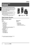
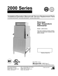
Guard Lock Safety-door Switch
D4BL
Safety Door
Switches
Release Protective Cover Locks Using
Controller Signals or Pushbutton Switches
after the Cutting Tool Stops Moving Due to
Inertia
D4BL
• A mechanical lock is applied automatically when the Operation
Key is inserted. A high level of safety is achieved using a
mechanism where the lock is only released when voltage is
applied to the solenoid.
• Conforms to EN (TÜV) standards corresponding to the CE
marking.
• Approved by UL, CSA, BIA, SUVA and CCC standards.
• The Switch contact is opened by a direct opening mechanism
(NC contacts only) when the protective cover is opened. Direct
opening mechanism that is EN-approved is indicated by
on
the Switch.
• Auxiliary release key ensures easy maintenance and unlocks
the door in the case of a power failure.
• Tough aluminum die-cast body incorporating a switch box with
degree of protection satisfying IP67, UL, and CSA TYPE6P, 13.
• Equipped with a horizontal and vertical conduit opening.
• Models incorporating easy-to-see indicators for monitoring and
those using an adjustable Operation Key for a double door are
available.
• The mounting direction of the head can be changed to allow the
Operation Key to be inserted from four directions.
Note: Be sure to read the “Safety Precautions” on page A-78 and the
“Precautions for All Safety Door Switches” on page A-2.
Model Number Structure
■ Model Number Legend
Switch
D4BL -
1
2
3
4
5
1. Conduit Size (2-conduit)
1: PG13.5
2: G1/2
3: 1/2-14NPT
2. Built-in Switch (with Safety Switch and Lock Monitor
Switch Contacts)
C: 1NC/1NO (slow-action) + 1NC (slow-action)
D: 2NC (slow-action) + 1NC (slow-action)
3. Head Mounting Direction
R: Four mounting directions possible (right-side mounting at shipping)
4. Door Lock and Release
(Auxiliary Release Key is Incorporated by All Models)
A: Mechanical lock/24-VDC solenoid release
B: Mechanical lock/110-VAC solenoid release
G: 24-VDC Solenoid lock/Mechanical release
5. Indicator
Blank: Without indicator
A:
10 to 115 VAC or VDC driving (with orange
and green LED indicator unit)
Operation Key (Order Separately)
D4BL - K
1
1. Operation Key Type
1: Horizontal mounting
2: Vertical mounting
3: Adjustable mounting (Horizontal)
Guard Lock Safety-door Switch
D4BL
A-67
Ordering Information
■ List of Models
Switches
Lock
method
Safety Door
Switches
Mechanical
lock
Conduit
size
PG13.5
G1/2
D4BL
Solenoid
lock
Voltage
for
solenoid
Without indicator
1NC/1NO+ 1NC
(Slow-action)
With LED indicator
1NC/1NO+ 1NC
(Slow-action)
Without indicator
2NC+ 1NC
(Slow-action)
With LED indicator
2NC+ 1NC
(Slow-action)
24 VDC
D4BL-1CRA
D4BL-1CRA-A
D4BL-1DRA
110 VAC
D4BL-1CRB
D4BL-1CRB-A
D4BL-1DRB
D4BL-1DRA-A
D4BL-1DRB-A
24 VDC
D4BL-2CRA
D4BL-2CRA-A
D4BL-2DRA
D4BL-2DRA-A
110 VAC
D4BL-2CRB
D4BL-2CRB-A
D4BL-2DRB
D4BL-2DRB-A
1/214NPT
24 VDC
D4BL-3CRA
D4BL-3CRA-A
D4BL-3DRA
D4BL-3DRA-A
110 VAC
D4BL-3CRB
D4BL-3CRB-A
D4BL-3DRB
D4BL-3DRB-A
Pg 13.5
24 VDC
D4BL-1CRG
D4BL-1CRG-A
D4BL-1DRG
D4BL-1DRG-A
G1/2
24 VDC
D4BL-2CRG
D4BL-2CRG-A
D4BL-2DRG
D4BL-2DRG-A
1/214NPT
24 VDC
D4BL-3CRG
D4BL-3CRG-A
D4BL-3DRG
D4BL-3DRG-A
Operation Keys (Order Separately)
Mounting type
Model
Horizontal mounting
D4BL-K1
Vertical mounting
D4BL-K2
Adjustable mounting
(Horizontal)
D4BL-K3
Specifications
■ Standards and EC Directives
• Conforms to the following EC Directives:
Machinery Directive
Low Voltage Directive
EN1088
■ Approved Standards
Agency
TÜV Rheinland
Standard
EN60947-5-1
File No.
R9451050
(Direct opening:
approved)
BIA
GS-ET-19
Mechanical lock:
9402293
Solenoid lock:
1998 20462-01
SUVA
SUVA
E6186/2.d
UL
UL508
E76675
CSA
CSA C22.2, No.14
LR45746
CQC (CCC)
GB14048.5
2003010305073836
Note: Ask your OMRON representative for information on approved
models.
A-68
Guard Lock Safety-door Switch
D4BL
■ Approved Standard Ratings
TÜV (EN60947-5-1), CCC (GB14048.5)
Item
Standard model
Indicator model
AC-15
AC-15
Rated operating current (Ie)
3A
6A
Rated operating voltage (Ue)
250 V
115 V
Safety Door
Switches
Utilization category
Use a 10-A fuse type gI or gG that conforms to IEC60269 as a short-circuit protection device.
UL/CSA (UL508, CSA C22.2 No. 14)
Rated voltage
Carry current
Current
Make
120 VAC
10 A
240 VAC
Volt-amperes
Break
60 A
6A
30 A
3A
D4BL
A300
Make
7,200 VA
Break
720 VA
Note: The UL/CSA approved rating for products with indicators (-A) is 6 A/115 VAC.
■ Characteristics
Degree of protection (See note 2.)
IP67 (EN60947-5-1) (This applies for the Switch only. The degree of protection for the key hole is
IP00.)
Durability (See note 3.)
Mechanical: 1,000,000 operations min.
Electrical: 500,000 operations min. (10-A resistive load at 250 VAC)
Operating speed
0.05 to 0.5 m/s
Operating frequency
30 operations/min max.
Rated frequency
50/60 Hz
Contact gap
2 x 2 mm min.
Operating characteristics
Direct opening force: 19.61 N min. (EN60947-5-1) (See note 4.)
Direct opening travel: 20 mm min. (EN60947-5-1) (See note 4.)
All stroke:
23 mm min.
Lock holding strength
700 N min. (GS-ET-19)
Insulation resistance
100 M Ω min. (at 500 VDC)
Rated insulation voltage (Ui)
300 V (EN60947-5-1)
Conventional enclosed thermal current 10 A (EN60947-5-1)
(Ithe)
Dielectric strength (Uimp)
Impulse dielectric strength (Uimp) 4 kV (EN60947-5-1) between terminals of different polarity, between
each terminal and ground, and between each terminal and non-current-carrying metal part;
2.5 kV between solenoid and ground (EN60947-5-1)
Conditional short-circuit current
100 A (EN60947-5-1)
Pollution degree (operating
environment)
3 (EN60947-5-1)
Protection against electric shock
Class I (with ground terminal)
Switching overvoltage
1,500 V max. (EN60947-5-1)
Contact resistance
50 mΩ max. (initial value)
Vibration resistance
Malfunction: 10 to 55 Hz, 0.35-mm single amplitude
Shock resistance
Destruction: 1,000 m/s2 min. (IEC68-2-27)
Malfunction: 300 m/s2 min. (IEC68-2-27)
Ambient temperature
Operating: –10°C to 55°C (with no icing)
Ambient humidity
Operating: 95% max.
Weight
Approx. 800 g
Note: 1. The above values are initial values.
2. The degree of protection is tested using the method specified by the standard (EN60947-5-1). Confirm that sealing properties are
sufficient for the operating conditions and environment beforehand. Although the switch box is protected from dust, oil or water
penetration, do not use the D4BL in places where dust, oil, water, or chemicals may enter through the key hole on the head, otherwise
Switch damage or malfunctioning may occur.
3. The durability is for an ambient temperature of 5°C to 35°C and an ambient humidity of 40% to 70%.
4. These figures are minimum requirements for safe operation.
Guard Lock Safety-door Switch
D4BL
A-69
Solenoid Coil Characteristics
Item
24-VDC mechanical lock models
+10%
−15%
Rated operating voltage
24 VDC
Current consumption
Approx. 300 mA
Insulation
Class F (130°C or less)
(100% ED)
110-VAC mechanical lock models
24-VDC solenoid lock models
+10%
−15%
110 VAC ±10% (50/60 Hz)
24 VDC
Approx. 98 mA
Approx. 300 mA
(100% ED)
Indicator Characteristics
Safety Door
Switches
Item
LED
Rated voltage
10 to 115 VAC/VDC
Current leakage
Approx. 1 mA
Color (LED)
Orange, green
D4BL
Connections
■ Contact Form (Diagrams Show State with Key Inserted and Lock
Engaged)
Model
Contact
D4BL-@C@@-@
Operating pattern
1NC/1NO+1NC
Lock position
32
31
11
Zb
ON
12
24
23
D4BL-@D@@-@
Remarks
2NC+1NC
Stroke
Operation Key
insertion completion position
The terminals 11-12
and 23-24 can be
used as unlike poles.
Extraction
completion
position
Lock position
31
Zb
32 11
ON
12
22
21
Note: The EN-approved direct opening mechanism is indicated by
Stroke
Operation Key
insertion completion position
Extraction
completion
position
Only NC contacts 11-12
and 31-32 have an
approved direct
opening mechanism.
NC contacts 11-12,
21-22, and 31-32
have an approved
direct opening
mechanism.
The terminals 11-12
and 21-22 can be
used as unlike poles.
on the Switch.
■ Contact Form 2NC + 2NC
(Safety circuit side)
(Monitor circuit side)
■ Indicator Unit
Dimensions
Internal Circuit
Four terminal plates
Two, 7 dia. Two LED indicators
(7)
(16)
R
(16)
2
10.6
(12.6)
(35)
26.2
(61.2)
A-70
Guard Lock Safety-door Switch
R
ZD
26.8 53.2 57.2
0.3
5.6
10 to 115 VAC/DC
D4BL
LED
Constant-current diode
■ Circuit Connection Example
1. Orange: Lights when the solenoid turns ON.
Green: Lights when the door opens.
2. Orange: Lights when the solenoid turns ON.
Green: Lights when power turns ON.
(Power supply side)
(Power supply side)
12
31
32
E1 (+)
11
12
31
32
Solenoid
23
24
LED (orange)
Solenoid
E2 (−)
23
24
LED (orange)
LED (green)
Auxiliary circuit
(monitor circuit)
Safety circuit
Auxiliary circuit
(monitor circuit)
(Ground side)
Safety circuit
(Ground side)
4. Orange: Lights when the solenoid turns ON.
Green: Lights when power turns ON.
(Power supply side)
(Power supply side)
E1 (+)
E1 (+)
12
31
11
32
12
31
32
Solenoid
21
22
LED (orange)
Solenoid
E2 (−)
21
22
LED (orange)
LED (green)
Auxiliary circuit
(monitor circuit)
Safety circuit
(Ground side)
E2 (−)
LED (green)
3. Orange: Lights when the solenoid turns ON.
Green: Lights when door closes.
11
D4BL
E1 (+)
11
Safety Door
Switches
• Terminals 11 and 32 are connected internally and so connect terminals 12 and 31 for safety-circuit input. (GS-ET-19).
• When using indicators, connect them to the auxiliary circuit side (monitor circuit) or the solenoid input terminals as shown below.
• The indicators can be used to confirm the open/closed status of the door, the ON/OFF status of the power supply, and the ON/OFF status of the
solenoid.
• Do not connect the indicators in parallel with the direct opening contact. If the indicators are broken, a short-circuit current may flow, causing
equipment to malfunction.
• The 24-VDC solenoid terminals have polarity. Confirm the polarity before wiring.
• Be sure to use a special pushbutton switch to stop and start machinery and release locks.
E2 (−)
LED (green)
Auxiliary circuit
(monitor circuit)
Safety circuit
(Ground side)
Guard Lock Safety-door Switch
D4BL
A-71
■ Connection Example with OMRON’s G9SA Safety Relay Unit
G9SA-321-T@ (24 VAC/VDC) + D4BL-@A-@, @B-@ (Mechanical Lock Type) Circuit Diagram
(Manual Reset)
Note: This example circuit is for Category 3.
Lock release signal
KM1
KM2
Safety Door
Switches
S2
S4
31
S1:
Safety Limit Switch
with direct opening mechanism
(D4B-N, D4N, D4F)
S2:
Guard Lock Safety-door Switch
S3:
Reset switch
S4:
Lock release switch
KM1 and KM2: Magnetic Contactor
M:
3-phase motor
32
11
D4BL
12
Guard
S1
Feedback loop
OPEN
KM1
S3
KM2
Stop signal
A1 A2 T11
T12
T31
T32
13 23 33 43 53 61
1
TH
a
K1
K2
3
4
K3
K3
SA
a
K1
b
K2
K4
Off-Delay
Timer
K4
Control
Circuit
b
2 K1
5
K2
JP
1
2
3
4
5
6
6
PE T21
T23 T22
A
14 24 34 44 54 62
B
KM1 KM2
Guard opens
Timing Chart
Limit switch S1
Guard Lock
Safety-door
Switch S2
Lock release
signal
Operation
instruction
Motor controller
KM1
Lock release
switch S4
Guard can be opened
KM2
Stop signal
Reset switch
S3
K1 and K2
(NC)
K1 and K2
(NO)
K3 and K4
(NC)
K3 and K4
(NO)
KM1 and KM2
(NC)
KM1 and KM2
(NO)
M
Operation
instruction
Motor rotation
OFF-delay time
A-72
Guard Lock Safety-door Switch
D4BL
G9SA-301 (24 VAC/VDC) + D4BL-@G-@ (Solenoid Lock Type) Circuit Diagram (Auto-reset)
Lock signal
S2
31
12
Safety Door
Switches
Note: 1. This example circuit is for Category 4.
2. The lock can be released at any time. Therefore, do not use a model
with a solenoid lock in applications where the operator may be
exposed to danger when the guard opens. Use a model with a
mechanical lock.
32
11
S1
D4BL
12
Feedback loop
OPEN
11
KM1
KM2
Operation signal
A1 A2 T11
T31
T12
T32
TH
a
13 23 33 41
3
4
1
K1
K1 K2
SA
K2
K1
b
K2
a
b
Control
Circuit
2
5
JP
1
2
3
4
5
6
6
PE T21
T23 T22
A
B
14 24 34 42
KM1 KM2
Operation
instruction
Timing Chart
Motor controller
Guard opens
KM1
Limit switch S1
Guard Lock Safety-door Switch S2
KM2
Operation signal
Lock signal
K1 and K2
(NC)
K1 and K2
(NO)
KM1 and KM2
(NC)
KM1 and KM2
(NO)
M
S1:
Safety Limit Switch
with direct opening mechanism
(D4B-N, D4N, D4F)
S2:
Guard Lock Safety-door Switch
KM1 and KM2: Magnetic Contactor
M:
3-phase motor
Guard Lock Safety-door Switch
D4BL
A-73
Nomenclature
D4BL-@C@@-@
D4BL-@D@@-@
Operation Key
Lock plate
Operation Key
Lock plate
Auxiliary release key
Lock monitor switch
Solenoid
Rotating drum
Operation plunger
Auxiliary release key
Lock monitor switch
Solenoid
Rotating drum
Operation plunger
Seal ring (NBR)
Auxiliary plunger
Seal packing (NBR)
Rotating lever
Safety Door
Switches
Seal ring (NBR)
Auxiliary plunger
Seal packing (NBR)
Rotating lever
Safety switch
Safety switch
D4BL
Seal packing (NBR)
Seal packing (NBR)
Conduit opening
Connection
(Pull out
terminal M3.5
horizontally)
Ground terminal M3.5
Conduit opening
Conduit opening
(Pull out
(Pull out
horizontally)
vertically)
The head can be changed
to any of four directions.
A-74
Guard Lock Safety-door Switch
D4BL
Connection
terminal M3.5
Ground terminal M3.5
Conduit opening
(Pull out
vertically)
Dimensions
Note: 1. All units are in millimeters unless otherwise indicated.
2. Unless otherwise specified, a tolerance of ±0.4 mm applies to all dimensions.
3. There are fluctuations in the contact ON/OFF timing for 2NC contacts. Confirm performance before application.
■ Switches
Safety Door
Switches
D4BL-@@@@-@
Four, M3.5 head
clamping screws
(116.5)
31.5
17
10
Red
7
Lock
protection
cap
15
Four, 5.3 dia.
mounting
holes
Four, M4
cover
clamping
screws
Cover
(123.5)
74±0.1
6.8
Conduit opening
37.5
D4BL
34.2
100±0.1
112+1
0
86+10
16
39.6
5.5
46.3
Indicators
Conduit opening
Operating Characteristics
D4BL-@@@@
Key insertion force
Key extraction force
19.61 N max.
19.61 N max.
Movement before being locked
15 mm max.
Four, M3.5 head
clamping screws
D4BL-2GRD-AT
31.5
(116.5)
10
34.2
37.5
Four, 5.3 dia.
Mounting
holes
Four, M4
cover
clamping
screws
Cover
74±0.1
6.8
100±0.1
112+10
86+10
5.5
16
39.6
Indictor
(Orange: Switch OFF)
Operating Characteristics
7
Indicator
(Green:
Solenoid ON).
(123.5)
Conduit opening
17
Conduit opening
Conduit opening
42.6
D4BL-2GRD-AT
Key insertion force
Key extraction force
19.61 N max.
19.61 N max.
Movement before being locked
15 mm max.
Guard Lock Safety-door Switch
D4BL
A-75
■ Operation Keys
Horizontal Mounting
Vertical Mounting
D4BL-K1
D4BL-K2
Red
Red
53.7
78.7
Safety Door
Switches
40.7
12
20±0.15
Long mounting hole
13
5.3 x 7.3 long mounting hole
7.3 15
25.8 15.6
25.8 15.6
40±0.15 52.4
Two, 2.65R
36
5.3
5.3
2.6
7.5
36
D4BL
20
11.8
5.6
5.6
4 dia.
4 dia.
Adjustable Mounting (Horizontal)
D4BL-K3
40
12 20
Red
25.8 15.6
(80.7)
40
30
Red
36
11.8
30
2.6
19.5
5.6
(37.8)
4 dia.
5.3 dia.
A-76
5.3 11.9 7.5
20
11.8
Guard Lock Safety-door Switch
17.5
M4 Allen-head bolt
34.6
D4BL
2.6
■ With Operation Key Inserted
Horizontal Mounting
D4BL + D4BL-K1
Red
Horizontal direction
Operation Key insertion radius
R ≥ 1200
53.5 min. 57 max.
(41)
53.5 min. 57 max.
(20±0.15)
(12)
Vertical direction
Operation Key insertion radius
R ≥ 1000
(20±0.15)
Safety Door
Switches
(41)
(35)
D4BL
Vertical direction
Operation Key insertion radius
R ≥ 1000
Vertical Mounting
D4BL + D4BL-K2
Horizontal direction
Operation Key insertion radius
R ≥ 1200
Red
54.5 min. 58 max.
(41)
54.5 min. 58 max.
(13)
(41)
(40±0.15)
(35)
Adjustable Mounting (Horizontal)
D4BL + D4BL-K3
Vertical direction
Operation Key insertion radius
R ≥ 1000
Red
Horizontal direction
Operation Key insertion radius
R ≥ 250
81.5 min. 85 max.
81.5 min. 85 max.
(41)
(41)
(40)
(35)
(30±0.15)
Note: 1. Unless otherwise specified, a tolerance of ±0.4 mm applies to all dimensions.
2. In the above diagrams, the Operation Key is inserted from the front.
Guard Lock Safety-door Switch
D4BL
A-77
Safety Precautions
Refer to the “Precautions for All Switches” on page I-2 and “Precautions for All Safety Door Switches” on page A-2.
■ Precautions for Correct Use
!CAUTION
Safety Door
Switches
Do not insert the Operation Key when the door is open.
The machine may operate, possibly resulting in injury.
Before using the machine, be sure to remove the shockabsorbing damper, which is provided before shipping.
Tightening Torque
Loose screws may result in malfunction. Tighten the screws to the
specified torques.
Type
■ Precautions for Safe Use
D4BL
• Do not use the Switch submersed in oil or water or in locations
continuously subject to splashes of oil or water. Doing so may result
in oil or water entering the Switch. (The IP67 degree of protection of
the Switch specifies the amount of water penetration after the
Switch is submerged in water for a certain period of time.)
• Although the Switch body is protected from the ingress of dust or
water, avoid the ingress of foreign substance through the key hole
on the head.
Otherwise, accelerated wear or breaking may result.
• Always attach the cover after completing wiring and before using
the Switch. Electric shock may occur if the Switch is used without
the cover attached.
Connect a fuse in series with the D4BL in series to protect it from
short-circuit damage. The value of the breaking current of the fuse
must be calculated by multiplying the rated current by 150% to 200%.
Torque
1
M3.5 terminal screw (including terminal screw) 0.59 to 0.78 N·m
2
Cover mounting screw
1.18 to 1.37 N·m
3
Head mounting screw
0.78 to 0.98 N·m
4
M5 body mounting screw (See note.)
4.90 to 5.88 N·m
5
Operation Key mounting screw
2.35 to 2.75 N·m
6
Connector
1.77 to 2.16 N·m
7
Cap screw
1.27 to 1.67 N·m
Note: Use M5 screws. Apply a torque of 4.90 to 5.88 N·m for an Allenhead bolt. For a pan head screw, apply a torque of 2.35 to
2.75 N·m
Two, M5 Operation Key mounting screw
Four, M3.5 head-mounting screw
To prevent the D4BL from burning due to overvoltage, insert a
protection fuse into the solenoid circuit.
Stopper Installation
Four, M4 cover-mounting screw
Do not use a Switch as a stopper. Be sure to install a stopper as
shown in the following illustration when mounting the Switch so that
the Operation Key is within 0.5 to 5 mm of the set zone.
Gap
Stopper
Conduit
Four, M5
switch-mounting screw
Conduit cap
Auxiliary Release Key
Set zone
The auxiliary release key is used to unlock the D4BL in case of
emergency or in case the power supply to the D4BL fails.
Switch
Use the enclosed Release Key to change the lock from LOCK to
UNLOCK so that the lock will be released and the door can be
opened. (Applies only to mechanical locks.)
LOCK
UNLOCK
Auxiliary
release key
The auxiliary release key applied to the door of a machine room
ensures the safety of people adjusting the equipment in the machine
room. If the auxiliary release key is set to UNLOCK, the door will not
be locked when the door is closed and no power will be supplied to
the equipment.
Whenever the lock has been changed to UNLOCK, always return it
to LOCK before using the Switch.
Do not use the auxiliary release key to start or stop machines.
To prevent the auxiliary release key from being handled carelessly by
unauthorized people, seal the auxiliary release key with sealing wax
and the provided seal cap to ensure IP67.
Make sure that the auxiliary release key is kept with the person in
charge.
Before attaching the cover to the D4BL, make sure that the auxiliary
release key position is set to LOCK.
A-78
Guard Lock Safety-door Switch
D4BL
Solenoid Lock Models
Operation Key
The solenoid lock locks the door only when power is supplied to the
solenoid. Therefore, the door will be unlocked if the power supply to
the solenoid stops. Therefore, do not use solenoid lock models for
machines that may be operating and dangerous even after the
machine stops operating.
The D4BL is provided with a shock-absorbing damper to protect the
D4BL from damage that may result from dropping the D4BL during
transportation. Be sure to remove the damper after mounting the
D4BL.
Switch and Operation Key Mounting
Observe the specified insertion radius for the Operation Key and
insert it in a direction perpendicular to the key hole.
Greater
than ±0.3
Incorrect
Mounting Dimensions
D4BL
Switch Mounting Dimensions
Four, M5
Incorrect
74±0.1
Greater
than ±0.3
100±0.1
Operation Key Mounting Holes
The Operation Key for the D4BL is different from the one for the
D4BS.
• Horizontal Mounting
D4BL-K1
Head Direction
Two, M5
20±0.1
• Vertical Mounting
D4BL-K2
Two, M5
40±0.1
• Adjustable Mounting (Horizontal)
D4BL-K3
The head can be mounted in four directions. To remove the head,
turn the head by 45° as shown in figures (A) and (B) below.
To change the direction of the head, make sure that the protruding
part of the rotating lever engages with the groove of the plunger.
Then turn the head clockwise or counterclockwise to the desired
direction. At that time, make sure that the groove of the plunger is
located under the rotating lever. If the direction of the head is not set
when the plunger is rotated by 45°, the groove of the plunger presses
the rotating lever. The head, plunger, or the built-in switch may be
damaged as a result.
Head Direction Changes
Two, M5
30±0.1
Safety Door
Switches
Mount the D4BL and Operation Key with four M5 screws with
washers and tighten each screw to the specified torque.
The mounting tolerance of the Operation Key is ±0.3 mm vertically or
horizontally. Be sure to mount the D4BL correctly without leaning,
otherwise the D4BL may soon break or wear out.
Left
Front
(45°)
(45°)
(A)
(B)
Back
Right
Head Bottom View
Operation plunger and
groove mechanism
Switch Top View
Rotation lever and
protruding part
Guard Lock Safety-door Switch
D4BL
A-79
Normal Positions of Rotating Lever and Plunger
Mounting the Cover
When tightening the cover, first check the specified torque, and then
tighten each screw to the that torque. Also, make sure that no foreign
material has entered the Switch.
Switch body
When mounting the cover, make sure that the cover and switch box
are properly aligned.
Rotating lever (with
protruding part)
Safety Door
Switches
Plunger (with groove)
Built-in switch
D4BL
Be sure to check the mechanical lock and solenoid release functions
when mounting the D4BL.
If the head direction is changed, recheck the tightening torque of
each of screw. Make sure that no foreign materials will enter through
the key hole on the head.
■ Processing and Connecting Cable/Conduit
The following procedures are recommended for mounting and wiring
the indicator unit securely.
Cable Connection Example
To ensure IP67, use OMRON’s SC-@M and Nippon Flex’s ABS08Pg13.5 and ABS-12 Pg13.5 Connectors.
1. Connect the wires to the terminals in the order shown below for
wiring efficiency.
Recommended cable: UL2464-type cable that is AWG20 to AWG18
(0.5 to 1.0 mm2) in size and has seven conductors
If the 1/2-14NPT is used, cover the cable and conduit end with
sealing tape to ensure IP67. Tighten the connector to a torque of
1.77 to 2.16 N·m.
Connect the indicator unit after connecting the seven-conductor
cable.
Tighten each wired terminal clockwise to a torque of 0.59 to
0.78 N·m.
Terminal no.
Lp (mm)
Lv (mm)
E1
30±2
80±2
E2
35±2
75±2
31
45±2
60±2
12
55±2
50±2
23 (21)
65±2
45±2
24 (22)
70±2
35±2
90±2
50±2
a (mm)
8± 1
Twist the wire two or three times and make sure that no bare wire
exists outside the terminal when tightening the terminal.
2. The insulation sheath of the seven-conductor cable must come
into contact with the wall of the conduit mouth, side A or side B.
Insulation sheath edge
Others
Properly attach and securely tighten the provided conduit cap to the
unused conduit opening when wiring the D4BL.
Do not touch the solenoid because the solenoid radiates heat while
power is being supplied.
ALL DIMENSIONS SHOWN ARE IN MILLIMETERS.
To convert millimeters into inches, multiply by 0.03937. To convert grams into ounces, multiply by 0.03527.
Cat. No. C100-E1-05
A-80
In the interest of product improvement, specifications are subject to change without notice.
Guard Lock Safety-door Switch
D4BL
Terms and Conditions of Sale
1. Offer; Acceptance. These terms and conditions (these "Terms") are deemed
part of all quotes, agreements, purchase orders, acknowledgments, price lists,
catalogs, manuals, brochures and other documents, whether electronic or in
writing, relating to the sale of products or services (collectively, the "Products")
by Omron Electronics LLC and its subsidiary companies (“Omron”). Omron
objects to any terms or conditions proposed in Buyer’s purchase order or other
documents which are inconsistent with, or in addition to, these Terms.
2. Prices; Payment Terms. All prices stated are current, subject to change without notice by Omron. Omron reserves the right to increase or decrease prices
on any unshipped portions of outstanding orders. Payments for Products are
due net 30 days unless otherwise stated in the invoice.
3. Discounts. Cash discounts, if any, will apply only on the net amount of invoices
sent to Buyer after deducting transportation charges, taxes and duties, and will
be allowed only if (i) the invoice is paid according to Omron’s payment terms
and (ii) Buyer has no past due amounts.
4. Interest. Omron, at its option, may charge Buyer 1-1/2% interest per month or
the maximum legal rate, whichever is less, on any balance not paid within the
stated terms.
5. Orders. Omron will accept no order less than $200 net billing.
6. Governmental Approvals. Buyer shall be responsible for, and shall bear all
costs involved in, obtaining any government approvals required for the importation or sale of the Products.
7. Taxes. All taxes, duties and other governmental charges (other than general
real property and income taxes), including any interest or penalties thereon,
imposed directly or indirectly on Omron or required to be collected directly or
indirectly by Omron for the manufacture, production, sale, delivery, importation, consumption or use of the Products sold hereunder (including customs
duties and sales, excise, use, turnover and license taxes) shall be charged to
and remitted by Buyer to Omron.
8. Financial. If the financial position of Buyer at any time becomes unsatisfactory
to Omron, Omron reserves the right to stop shipments or require satisfactory
security or payment in advance. If Buyer fails to make payment or otherwise
comply with these Terms or any related agreement, Omron may (without liability and in addition to other remedies) cancel any unshipped portion of Products sold hereunder and stop any Products in transit until Buyer pays all
amounts, including amounts payable hereunder, whether or not then due,
which are owing to it by Buyer. Buyer shall in any event remain liable for all
unpaid accounts.
9. Cancellation; Etc. Orders are not subject to rescheduling or cancellation
unless Buyer indemnifies Omron against all related costs or expenses.
10. Force Majeure. Omron shall not be liable for any delay or failure in delivery
resulting from causes beyond its control, including earthquakes, fires, floods,
strikes or other labor disputes, shortage of labor or materials, accidents to
machinery, acts of sabotage, riots, delay in or lack of transportation or the
requirements of any government authority.
11. Shipping; Delivery. Unless otherwise expressly agreed in writing by Omron:
a. Shipments shall be by a carrier selected by Omron; Omron will not drop ship
except in “break down” situations.
b. Such carrier shall act as the agent of Buyer and delivery to such carrier shall
constitute delivery to Buyer;
c. All sales and shipments of Products shall be FOB shipping point (unless otherwise stated in writing by Omron), at which point title and risk of loss shall
pass from Omron to Buyer; provided that Omron shall retain a security interest in the Products until the full purchase price is paid;
d. Delivery and shipping dates are estimates only; and
e. Omron will package Products as it deems proper for protection against normal handling and extra charges apply to special conditions.
12. Claims. Any claim by Buyer against Omron for shortage or damage to the
Products occurring before delivery to the carrier must be presented in writing
to Omron within 30 days of receipt of shipment and include the original transportation bill signed by the carrier noting that the carrier received the Products
from Omron in the condition claimed.
13. Warranties. (a) Exclusive Warranty. Omron’s exclusive warranty is that the
Products will be free from defects in materials and workmanship for a period of
twelve months from the date of sale by Omron (or such other period expressed
in writing by Omron). Omron disclaims all other warranties, express or implied.
(b) Limitations. OMRON MAKES NO WARRANTY OR REPRESENTATION,
EXPRESS OR IMPLIED, ABOUT NON-INFRINGEMENT, MERCHANTABIL-
14.
15.
16.
17.
18.
ITY OR FITNESS FOR A PARTICULAR PURPOSE OF THE PRODUCTS.
BUYER ACKNOWLEDGES THAT IT ALONE HAS DETERMINED THAT THE
PRODUCTS WILL SUITABLY MEET THE REQUIREMENTS OF THEIR
INTENDED USE. Omron further disclaims all warranties and responsibility of
any type for claims or expenses based on infringement by the Products or otherwise of any intellectual property right. (c) Buyer Remedy. Omron’s sole obligation hereunder shall be, at Omron’s election, to (i) replace (in the form
originally shipped with Buyer responsible for labor charges for removal or
replacement thereof) the non-complying Product, (ii) repair the non-complying
Product, or (iii) repay or credit Buyer an amount equal to the purchase price of
the non-complying Product; provided that in no event shall Omron be responsible for warranty, repair, indemnity or any other claims or expenses regarding
the Products unless Omron’s analysis confirms that the Products were properly handled, stored, installed and maintained and not subject to contamination, abuse, misuse or inappropriate modification. Return of any Products by
Buyer must be approved in writing by Omron before shipment. Omron Companies shall not be liable for the suitability or unsuitability or the results from the
use of Products in combination with any electrical or electronic components,
circuits, system assemblies or any other materials or substances or environments. Any advice, recommendations or information given orally or in writing,
are not to be construed as an amendment or addition to the above warranty.
See http://oeweb.omron.com or contact your Omron representative for published information.
Limitation on Liability; Etc. OMRON COMPANIES SHALL NOT BE LIABLE
FOR SPECIAL, INDIRECT, INCIDENTAL, OR CONSEQUENTIAL DAMAGES,
LOSS OF PROFITS OR PRODUCTION OR COMMERCIAL LOSS IN ANY
WAY CONNECTED WITH THE PRODUCTS, WHETHER SUCH CLAIM IS
BASED IN CONTRACT, WARRANTY, NEGLIGENCE OR STRICT LIABILITY.
Further, in no event shall liability of Omron Companies exceed the individual
price of the Product on which liability is asserted.
Indemnities. Buyer shall indemnify and hold harmless Omron Companies and
their employees from and against all liabilities, losses, claims, costs and
expenses (including attorney's fees and expenses) related to any claim, investigation, litigation or proceeding (whether or not Omron is a party) which arises
or is alleged to arise from Buyer's acts or omissions under these Terms or in
any way with respect to the Products. Without limiting the foregoing, Buyer (at
its own expense) shall indemnify and hold harmless Omron and defend or settle any action brought against such Companies to the extent based on a claim
that any Product made to Buyer specifications infringed intellectual property
rights of another party.
Property; Confidentiality. Any intellectual property in the Products is the exclusive property of Omron Companies and Buyer shall not attempt to duplicate it
in any way without the written permission of Omron. Notwithstanding any
charges to Buyer for engineering or tooling, all engineering and tooling shall
remain the exclusive property of Omron. All information and materials supplied
by Omron to Buyer relating to the Products are confidential and proprietary,
and Buyer shall limit distribution thereof to its trusted employees and strictly
prevent disclosure to any third party.
Export Controls. Buyer shall comply with all applicable laws, regulations and
licenses regarding (i) export of products or information; (iii) sale of products to
“forbidden” or other proscribed persons; and (ii) disclosure to non-citizens of
regulated technology or information.
Miscellaneous. (a) Waiver. No failure or delay by Omron in exercising any right
and no course of dealing between Buyer and Omron shall operate as a waiver
of rights by Omron. (b) Assignment. Buyer may not assign its rights hereunder
without Omron's written consent. (c) Law. These Terms are governed by the
law of the jurisdiction of the home office of the Omron company from which
Buyer is purchasing the Products (without regard to conflict of law principles). (d) Amendment. These Terms constitute the entire agreement between
Buyer and Omron relating to the Products, and no provision may be changed
or waived unless in writing signed by the parties. (e) Severability. If any provision hereof is rendered ineffective or invalid, such provision shall not invalidate
any other provision. (f) Setoff. Buyer shall have no right to set off any amounts
against the amount owing in respect of this invoice. (g) Definitions. As used
herein, “including” means “including without limitation”; and “Omron Companies” (or similar words) mean Omron Corporation and any direct or indirect
subsidiary or affiliate thereof.
Certain Precautions on Specifications and Use
1. Suitability of Use. Omron Companies shall not be responsible for conformity
with any standards, codes or regulations which apply to the combination of the
Product in the Buyer’s application or use of the Product. At Buyer’s request,
Omron will provide applicable third party certification documents identifying
ratings and limitations of use which apply to the Product. This information by
itself is not sufficient for a complete determination of the suitability of the Product in combination with the end product, machine, system, or other application
or use. Buyer shall be solely responsible for determining appropriateness of
the particular Product with respect to Buyer’s application, product or system.
Buyer shall take application responsibility in all cases but the following is a
non-exhaustive list of applications for which particular attention must be given:
(i) Outdoor use, uses involving potential chemical contamination or electrical
interference, or conditions or uses not described in this document.
(ii) Use in consumer products or any use in significant quantities.
(iii) Energy control systems, combustion systems, railroad systems, aviation
systems, medical equipment, amusement machines, vehicles, safety equipment, and installations subject to separate industry or government regulations.
(iv) Systems, machines and equipment that could present a risk to life or property. Please know and observe all prohibitions of use applicable to this Product.
NEVER USE THE PRODUCT FOR AN APPLICATION INVOLVING SERIOUS
RISK TO LIFE OR PROPERTY OR IN LARGE QUANTITIES WITHOUT
ENSURING THAT THE SYSTEM AS A WHOLE HAS BEEN DESIGNED TO
2.
3.
4.
5.
ADDRESS THE RISKS, AND THAT THE OMRON’S PRODUCT IS PROPERLY RATED AND INSTALLED FOR THE INTENDED USE WITHIN THE
OVERALL EQUIPMENT OR SYSTEM.
Programmable Products. Omron Companies shall not be responsible for the
user’s programming of a programmable Product, or any consequence thereof.
Performance Data. Data presented in Omron Company websites, catalogs
and other materials is provided as a guide for the user in determining suitability and does not constitute a warranty. It may represent the result of Omron’s
test conditions, and the user must correlate it to actual application requirements. Actual performance is subject to the Omron’s Warranty and Limitations
of Liability.
Change in Specifications. Product specifications and accessories may be
changed at any time based on improvements and other reasons. It is our practice to change part numbers when published ratings or features are changed,
or when significant construction changes are made. However, some specifications of the Product may be changed without any notice. When in doubt, special part numbers may be assigned to fix or establish key specifications for
your application. Please consult with your Omron’s representative at any time
to confirm actual specifications of purchased Product.
Errors and Omissions. Information presented by Omron Companies has been
checked and is believed to be accurate; however, no responsibility is assumed
for clerical, typographical or proofreading errors or omissions.
&RPSOHWH¦7HUPVDQG&RQGLWLRQVRI6DOH§IRUSURGXFWSXUFKDVHDQGXVHDUHRQ2PURQ©VZHEVLWH
DWZZZRPURQFRPRHL¤XQGHUWKH¦$ERXW8V§WDELQWKH/HJDO0DWWHUVVHFWLRQ
$//',0(16,2166+2:1$5(,10,//,0(7(56
7RFRQYHUWPLOOLPHWHUVLQWRLQFKHVPXOWLSO\E\7RFRQYHUWJUDPVLQWRRXQFHVPXOWLSO\E\
20521(/(&7521,&6//&
20521&$1$'$,1&
2QH&RPPHUFH'ULYH
6FKDXPEXUJ,/
)RU86WHFKQLFDOVXSSRUWRURWKHULQTXLULHV
0LOQHU$YHQXH
7RURQWR2QWDULR0%9
2052121/,1(
*OREDOKWWSZZZRPURQFRP
86$KWWSZZZRPURQFRPRHL
&DQDGDKWWSZZZRPURQFD
Cat. No. GC SAFETY-3
07/05
Specifications subject to change without notice
Printed in USA