1
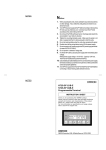
Cat. No. I525-E1-1
USER’S MANUAL
CompoBus/D (DeviceNet)
Communications Card
MODEL 3G3FV-PDRT1-SIN
(For SYSDRIVE 3G3FV High-function General-purpose Inverters)
Thank you for choosing a 3G3FV High-function General-purpose Inverter and
CompoBus/D Communications Card. This manual describes the specifications
and operating methods of the CompoBus/D Communications Card used for
exchanging data between an Inverter and a Programmable Controller.
Specifically, it describes the operation methods, communications methods, and
data setting methods of the 3G3FV-PDRT1-SIN CompoBus/D Communications
Card. Proper use and handling of the product will help ensure proper product
performance, will length product life, and may prevent possible accidents.
Please read this manual thoroughly and handle and operate the product with care.
For details about the 3G3FV Inverter and CompoBus/D communications system,
refer to the following manuals.
SYSDRIVE 3G3FV User’s Manual (I516)
CompoBus/D Operation Manual (W267)
NOTICE
1. This manual describes the functions of the product and relations with other products. You should assume that anything not described in this manual is not possible.
2. The name “SYSMAC” in this manual refers to the SYSMAC C200HX/HG/HE and
CV-series Programmable Controllers that can be connected to a CompoBus/D
System. (C200HS Programmable Controllers support only the remote I/O function.)
3. Although care has been given in documenting the product, please contact your
OMRON representative if you have any suggestions on improving this manual.
4. The product contains potentially dangerous parts under the cover. Do not attempt
to open the cover under any circumstances. Doing so may result in injury or death
and may damage the product. Never attempt to repair or disassemble the product.
5. We recommend that you add the following precautions to any instruction manuals
you prepare for the system into which the product is being installed.
S Precautions on the dangers of high-voltage equipment.
S Precautions on touching the terminals of the product even after power has been
turned off. (These terminals are live even with the power turned off.)
6. Specifications and functions may be changed without notice in order to improve
product performance.
Items to Check Before Unpacking
Check the following items before removing the product from the package:
S Has the correct product been delivered (i.e., the correct model number and specifications)?
S Has the product been damaged in shipping?
S Are any screws or bolts loose?
S Have all accessories been delivered together with or attached to the product?
Notice:
OMRON products are manufactured for use according to proper procedures by a qualified
operator and only for the purposes described in this manual.
The following conventions are used to indicate and classify precautions in this manual. Always heed the information provided with them. Failure to heed precautions can result in injury to people or damage to property.
!
DANGER
Indicates an imminently hazardous situation which, if not avoided, will result in death
or serious injury.
!
WARNING
Indicates a potentially hazardous situation which, if not avoided, could result in death
or serious injury.
! Caution
Indicates a potentially hazardous situation which, if not avoided, may result in minor
or moderate injury, or property damage.
OMRON Product References
All OMRON products are capitalized in this manual. The word “Unit” is also capitalized when
it refers to an OMRON product, regardless of whether or not it appears in the proper name
of the product.
The abbreviation “Ch,” which appears in some displays and on some OMRON products,
often means “word” and is abbreviated “Wd” in documentation in this sense.
The abbreviation “PC” means Programmable Controller and is not used as an abbreviation
for anything else.
Visual Aids
The following headings appear in the left column of the manual to help you locate different
types of information.
Note Indicates information of particular interest for efficient and convenient operation of the product.
OMRON, 1998
All rights reserved. No part of this publication may be reproduced, stored in a retrieval system, or transmitted,
in any form, or by any means, mechanical, electronic, photocopying, recording, or otherwise, without the prior
written permission of OMRON.
No patent liability is assumed with respect to the use of the information contained herein. Moreover, because
OMRON is constantly striving to improve its high-quality products, the information contained in this manual
is subject to change without notice. Every precaution has been taken in the preparation of this manual. Nevertheless, OMRON assumes no responsibility for errors or omissions. Neither is any liability assumed for damages resulting from the use of the information contained in this publication.
H Installation and Wiring Precautions
!
WARNING
Never touch any internal parts of the Inverter. Doing so may result in electric shock.
!
WARNING
Install, remove, or wire the Optional Card only after turning OFF the Inverter, making
sure that all the indicators of the Inverter are OFF, and waiting for the time specified
on the front cover of the Inverter to elapse. Not doing so may result in electric shock.
!
WARNING
Do not damage, press, or put excessive stress or heavy objects on the cables. Doing
so may result in electric shock, product malfunction, or product damage.
! Caution
Do not touch the parts of the Optional Card by hand. Otherwise, static electricity may
damage the Optional Card.
! Caution
Be sure that the connector of the Optional Card is firmly in place on the Inverter. Improper connection may cause injury, product malfunction, or product damage.
H Adjustment Precautions
! Caution
Be careful when changing settings. Not doing so may result in injury or product damage.
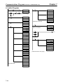
Table of Contents
Chapter 1. Functions and System Configuration . . . . . . . . . . . . . . . . . 1-1
1-1 Functions . . . . . . . . . . . . . . . . . . . . . . . . . . . . . . . . . . . . . . . . . . . . . . . . . . . . . . . . . . . . . . . . . . 1-2
1-2 CompoBus/D Features . . . . . . . . . . . . . . . . . . . . . . . . . . . . . . . . . . . . . . . . . . . . . . . . . . . . . . . . 1-5
1-3 CompoBus/D System Configuration . . . . . . . . . . . . . . . . . . . . . . . . . . . . . . . . . . . . . . . . . . . . . 1-7
1-3-1 System Configuration . . . . . . . . . . . . . . . . . . . . . . . . . . . . . . . . . . . . . . . . . . . . . . . . . . 1-7
1-3-2 Configurator Overview . . . . . . . . . . . . . . . . . . . . . . . . . . . . . . . . . . . . . . . . . . . . . . . . . 1-8
1-3-3 CompoBus/D Communications Specifications . . . . . . . . . . . . . . . . . . . . . . . . . . . . . . 1-10
1-3-4 Inverter . . . . . . . . . . . . . . . . . . . . . . . . . . . . . . . . . . . . . . . . . . . . . . . . . . . . . . . . . . . . . 1-10
Chapter 2. CompoBus/D Communications Line Design . . . . . . . . . . . 2-1
2-1 Network Configuration Overview . . . . . . . . . . . . . . . . . . . . . . . . . . . . . . . . . . . . . . . . . . . . . . .
2-1-1 Network Components . . . . . . . . . . . . . . . . . . . . . . . . . . . . . . . . . . . . . . . . . . . . . . . . . .
2-1-2 Connections . . . . . . . . . . . . . . . . . . . . . . . . . . . . . . . . . . . . . . . . . . . . . . . . . . . . . . . . . .
2-2 Network Configuration Restrictions . . . . . . . . . . . . . . . . . . . . . . . . . . . . . . . . . . . . . . . . . . . . .
2-2-1 Baud Rate and Communications Distance . . . . . . . . . . . . . . . . . . . . . . . . . . . . . . . . . .
2-2-2 Locating Terminating Resistors . . . . . . . . . . . . . . . . . . . . . . . . . . . . . . . . . . . . . . . . . .
2-3 Communications Power Supply . . . . . . . . . . . . . . . . . . . . . . . . . . . . . . . . . . . . . . . . . . . . . . . .
2-3-1 Locating the Communications Power Supply . . . . . . . . . . . . . . . . . . . . . . . . . . . . . . .
2-3-2 Step 1: Determining the Best Location for the Power Supply from a Graph . . . . . . .
2-3-3 Step 2: Calculating the Best Location of the Actual Nodes . . . . . . . . . . . . . . . . . . . . .
2-3-4 Step 3: Splitting the System into Multiple Power Supplies . . . . . . . . . . . . . . . . . . . . .
2-3-5 Dual Power Supplies . . . . . . . . . . . . . . . . . . . . . . . . . . . . . . . . . . . . . . . . . . . . . . . . . . .
2-4 Communications Line Noise Prevention . . . . . . . . . . . . . . . . . . . . . . . . . . . . . . . . . . . . . . . . . .
2-4-1 Communications Line Noise . . . . . . . . . . . . . . . . . . . . . . . . . . . . . . . . . . . . . . . . . . . .
2-4-2 Grounding the Network . . . . . . . . . . . . . . . . . . . . . . . . . . . . . . . . . . . . . . . . . . . . . . . .
2-4-3 Communications Power Supply Noise Prevention . . . . . . . . . . . . . . . . . . . . . . . . . . . .
2-4-4 Noise Prevention Wiring . . . . . . . . . . . . . . . . . . . . . . . . . . . . . . . . . . . . . . . . . . . . . . . .
2-4-5 Noise Prevention for Peripheral Devices . . . . . . . . . . . . . . . . . . . . . . . . . . . . . . . . . . .
2-2
2-2
2-3
2-4
2-4
2-5
2-6
2-6
2-9
2-11
2-13
2-14
2-15
2-15
2-15
2-16
2-17
2-18
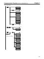
Chapter 3. Setup and Wiring . . . . . . . . . . . . . . . . . . . . . . . . . . . . . . . . . 3-1
3-1 Nomenclature and Settings . . . . . . . . . . . . . . . . . . . . . . . . . . . . . . . . . . . . . . . . . . . . . . . . . . . .
3-1-1 Names of Parts . . . . . . . . . . . . . . . . . . . . . . . . . . . . . . . . . . . . . . . . . . . . . . . . . . . . . . .
3-1-2 Terminal Block . . . . . . . . . . . . . . . . . . . . . . . . . . . . . . . . . . . . . . . . . . . . . . . . . . . . . . .
3-1-3 Operation Indicators . . . . . . . . . . . . . . . . . . . . . . . . . . . . . . . . . . . . . . . . . . . . . . . . . . .
3-1-4 Baud Rate and Node Address Settings . . . . . . . . . . . . . . . . . . . . . . . . . . . . . . . . . . . . .
3-2 Installation and Wiring . . . . . . . . . . . . . . . . . . . . . . . . . . . . . . . . . . . . . . . . . . . . . . . . . . . . . . .
3-2-1 CompoBus/D Communications Card Installation . . . . . . . . . . . . . . . . . . . . . . . . . . . .
3-2-2 Communications Cable Wiring . . . . . . . . . . . . . . . . . . . . . . . . . . . . . . . . . . . . . . . . . .
3-2
3-2
3-2
3-3
3-4
3-5
3-5
3-6
Chapter 4. CompoBus/D System Startup . . . . . . . . . . . . . . . . . . . . . . . 4-1
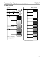
4-1 SYSMAC Word Allocations and Scan List . . . . . . . . . . . . . . . . . . . . . . . . . . . . . . . . . . . . . . . .
4-1-1 Overview and Restrictions of Word Allocations . . . . . . . . . . . . . . . . . . . . . . . . . . . . .
4-1-2 Scan Lists . . . . . . . . . . . . . . . . . . . . . . . . . . . . . . . . . . . . . . . . . . . . . . . . . . . . . . . . . . .
4-1-3 Fixed Word Allocations . . . . . . . . . . . . . . . . . . . . . . . . . . . . . . . . . . . . . . . . . . . . . . . .
4-1-4 Free Allocations . . . . . . . . . . . . . . . . . . . . . . . . . . . . . . . . . . . . . . . . . . . . . . . . . . . . . .
4-2 SYSDRIVE 3G3FV Settings . . . . . . . . . . . . . . . . . . . . . . . . . . . . . . . . . . . . . . . . . . . . . . . . . . .
4-2-1 Frequency Reference Selection . . . . . . . . . . . . . . . . . . . . . . . . . . . . . . . . . . . . . . . . . .
4-2-2 Inverter Run Command Selection . . . . . . . . . . . . . . . . . . . . . . . . . . . . . . . . . . . . . . . .
4-2-3 CompoBus/D Communications Settings . . . . . . . . . . . . . . . . . . . . . . . . . . . . . . . . . . .
4-2-4 Frequency Reference Settings and Display Units . . . . . . . . . . . . . . . . . . . . . . . . . . . .
4-3 Startup Procedure . . . . . . . . . . . . . . . . . . . . . . . . . . . . . . . . . . . . . . . . . . . . . . . . . . . . . . . . . . . .
4-2
4-2
4-3
4-5
4-9
4-13
4-13
4-13
4-14
4-15
4-16
Table of Contents
Chapter 5. CompoBus/D Communications Card Operations . . . . . . . 5-1
5-1 Remote I/O . . . . . . . . . . . . . . . . . . . . . . . . . . . . . . . . . . . . . . . . . . . . . . . . . . . . . . . . . . . . . . . . .
5-1-1 Standard Remote I/O (Initial Setting) . . . . . . . . . . . . . . . . . . . . . . . . . . . . . . . . . . . . .
5-1-2 Types of Remote I/O Operation . . . . . . . . . . . . . . . . . . . . . . . . . . . . . . . . . . . . . . . . . .
5-2 Message Communications (DeviceNet Explicit Messages) . . . . . . . . . . . . . . . . . . . . . . . . . . .
5-2-1 Overview of Message Communications (Explicit Message Operations) . . . . . . . . . . .
5-2-2 Sending and Receiving Messages with C200HX/HG/HE PCs . . . . . . . . . . . . . . . . . .
5-2-3 SYSMAC CV-series Message Transmission . . . . . . . . . . . . . . . . . . . . . . . . . . . . . . . .
5-2-4 Overview of Messages and Responses . . . . . . . . . . . . . . . . . . . . . . . . . . . . . . . . . . . . .
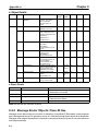
5-2-5 Motor Data Objects: Class 28 Hex . . . . . . . . . . . . . . . . . . . . . . . . . . . . . . . . . . . . . . . .
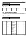
5-2-6 Control Supervisor Objects: Class 29 Hex . . . . . . . . . . . . . . . . . . . . . . . . . . . . . . . . . .
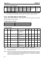
5-2-7 AC/DC Drive Objects: Class 2A Hex . . . . . . . . . . . . . . . . . . . . . . . . . . . . . . . . . . . . .
5-3 Switching Remote I/O Operation . . . . . . . . . . . . . . . . . . . . . . . . . . . . . . . . . . . . . . . . . . . . . . .
5-4 Special Remote I/O Operation . . . . . . . . . . . . . . . . . . . . . . . . . . . . . . . . . . . . . . . . . . . . . . . . .
5-4-1 Overview of Special Remote I/O . . . . . . . . . . . . . . . . . . . . . . . . . . . . . . . . . . . . . . . . .
5-4-2 Special Remote I/O Communications Timing . . . . . . . . . . . . . . . . . . . . . . . . . . . . . . .
5-4-3 Inputting Control/Frequency . . . . . . . . . . . . . . . . . . . . . . . . . . . . . . . . . . . . . . . . . . . .
5-4-4 Inverter Monitoring Functions . . . . . . . . . . . . . . . . . . . . . . . . . . . . . . . . . . . . . . . . . . .
5-4-5 Parameter Constant Reading and Writing . . . . . . . . . . . . . . . . . . . . . . . . . . . . . . . . . .
5-2
5-3
5-6
5-8
5-8
5-9
5-13
5-15
5-16
5-17
5-20
5-24
5-27
5-27
5-29
5-30
5-32
5-39
Chapter 6. Communications Errors . . . . . . . . . . . . . . . . . . . . . . . . . . . 6-1
6-1
6-2
6-3
6-4
Communications Line Errors . . . . . . . . . . . . . . . . . . . . . . . . . . . . . . . . . . . . . . . . . . . . . . . . . .
Message Communications Errors . . . . . . . . . . . . . . . . . . . . . . . . . . . . . . . . . . . . . . . . . . . . . . .
Special Remote I/O Errors . . . . . . . . . . . . . . . . . . . . . . . . . . . . . . . . . . . . . . . . . . . . . . . . . . . . .
Inverter Faults . . . . . . . . . . . . . . . . . . . . . . . . . . . . . . . . . . . . . . . . . . . . . . . . . . . . . . . . . . . . . .
6-2
6-5
6-6
6-7
Chapter 7. Communications Programs (SYSMAC C200HX/HG/HE PCs) . . . 7-1
7-1 Standard Remote I/O Programming . . . . . . . . . . . . . . . . . . . . . . . . . . . . . . . . . . . . . . . . . . . . .
7-2 Message Communications Programming . . . . . . . . . . . . . . . . . . . . . . . . . . . . . . . . . . . . . . . . .
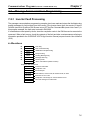
7-2-1 Inverter Fault Processing . . . . . . . . . . . . . . . . . . . . . . . . . . . . . . . . . . . . . . . . . . . . . . .
7-2-2 Reading/Writing Data . . . . . . . . . . . . . . . . . . . . . . . . . . . . . . . . . . . . . . . . . . . . . . . . . .
7-3 Special Remote I/O Programs . . . . . . . . . . . . . . . . . . . . . . . . . . . . . . . . . . . . . . . . . . . . . . . . . .
7-3-1 Simple Operation Programs . . . . . . . . . . . . . . . . . . . . . . . . . . . . . . . . . . . . . . . . . . . . .
7-3-2 Reading Parameter Data . . . . . . . . . . . . . . . . . . . . . . . . . . . . . . . . . . . . . . . . . . . . . . . .
7-3-3 Writing Parameter Data . . . . . . . . . . . . . . . . . . . . . . . . . . . . . . . . . . . . . . . . . . . . . . . .
7-2
7-5
7-5
7-8
7-13
7-13
7-19
7-22
Chapter 8. Appendices . . . . . . . . . . . . . . . . . . . . . . . . . . . . . . . . . . . . . . 8-1
8-1 Specifications . . . . . . . . . . . . . . . . . . . . . . . . . . . . . . . . . . . . . . . . . . . . . . . . . . . . . . . . . . . . . . . 8-2
8-2 Objects . . . . . . . . . . . . . . . . . . . . . . . . . . . . . . . . . . . . . . . . . . . . . . . . . . . . . . . . . . . . . . . . . . . . 8-3
8-2-1 Identify Objects (Identification Information): Class 01 Hex . . . . . . . . . . . . . . . . . . . . 8-3
8-2-2 Message Router Objects: Class 02 Hex . . . . . . . . . . . . . . . . . . . . . . . . . . . . . . . . . . . . 8-4
8-2-3 DeviceNet Objects: Class 03 Hex . . . . . . . . . . . . . . . . . . . . . . . . . . . . . . . . . . . . . . . . 8-5
8-2-4 Assembly Objects: Class 04 Hex . . . . . . . . . . . . . . . . . . . . . . . . . . . . . . . . . . . . . . . . . 8-6
8-2-5 DeviceNet Connection Objects: Class 05 Hex . . . . . . . . . . . . . . . . . . . . . . . . . . . . . . . 8-7
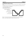
8-3 CompoBus/D Communications Response Time . . . . . . . . . . . . . . . . . . . . . . . . . . . . . . . . . . . . 8-11
Index . . . . . . . . . . . . . . . . . . . . . . . . . . . . . . . . . . . . . . . . . .
Revision History . . . . . . . . . . . . . . . . . . . . . . . . . . . . . . . . .
I-1
R-1
1
Chapter 1
Functions and System
Configuration
1-1
1-2
1-3
Functions
CompoBus/D Features
CompoBus/D System Configuration
Functions and System Configuration
1-1
Chapter 1
Functions
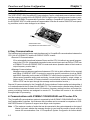
The 3G3FV-PDRT1-SIN CompoBus/D Communications Card is a dedicated communications interface
card that makes it possible for the SYSDRIVE 3G3FV High-function General-purpose Inverter to communicate with SYSMAC Programmable Controllers. Installing a CompoBus/D Communications Card in
the SYSDRIVE 3G3FV Inverter permits a Programmable Controller to monitor RUN/STOP and operating conditions, and to make changes in set values.
3G3FV-PDRT1-SIN
CompoBus/D Communications Card
H Easy Communications
The following two functions can be used simultaneously in CompoBus/D communications between the
CPU Unit of a SYSMAC PC and the SYSDRIVE 3G3FV Inverter.
S Remote I/O Communications
I/O is automatically transferred between Slaves and the CPU Unit without any special programming in the CPU Unit. (Automatically transmits Inverter control inputs such as RUN or STOP from
a SYSMAC PC to the SYSDRIVE 3G3FV Inverter and returns operation status of the Inverter or
output frequency monitor data. )
S Message Communications
Message communications are performed between a CPU Unit to which a Master Unit is mounted
and Slaves (SYSDRIVE 3G3FV Inverters) by executing specific instructions (such as CMND
and IOWR, depending on the model of SYSMAC PC used) from the program in the CPU Unit.
(Allows some parameter setting and monitoring, Inverter output frequency, output voltage, or
output current. If the remote I/O communications is not performed, Inverter control data such as
RUN or STOP can be input through this message communications function.)
Remote I/O communications for the CompoBus/D Communications Card are performed using either 4
or 6 words allocated in the I/O Area of the SYSMAC PC. The Inverter can be controlled using remote I/O
communications because the basic control I/O functions, frequency setting functions, and output frequency monitoring functions are assigned to remote I/O. The allows the Inverter to be controlled
through simple I/O processing.
H Communications with SYSMAC C200HX/HG/HE and CV-series PCs
The CompoBus/D communications system is supported by both SYSMAC C200HX/HG/HE and CV-series Programmable Controllers. Up to twice as many Inverters can be connected in comparison to SYSMAC BUS Remote I/O Systems to support even larger control systems.
Note 1. The maximum number of nodes that can be connected to the system depends on the type of
Master Unit used, whether the message function is used, and the number of words used by
remote I/O communications. See 1-3 CompoBus/D System Configuration for further details.
1-2
Functions and System Configuration
Chapter 1
Note 2. The SYSMAC CV Series includes the CV1000, CV2000, and CVM1 Programmable Controllers. SYSMAC C200HS PCs support only remote I/O communications.
H Multi-vendor Network
The CompoBus/D conforms to the DeviceNet open field network specification, which means that devices (Masters and Slaves) produced by other manufacturers can also be connected to the Network.
The CompoBus/D Communications Card supports the DeviceNet AC/DC drive object, so that the functions available for CompoBus/D communications can be used in DeviceNet communications.
H Choice of Communications Functions
The CompoBus/D Communications Card has various functions to choose from to suit the Inverter applications.
S Remote I/O Communications
Either basic remote I/O control or special remote I/O can be chosen for remote I/O allocation to
suit the application. Special I/O control can be used to control and set all functions for 3G3FV-series Inverters.
S Message Communications
Basic Inverter control and monitoring is possible with DeviceNet explicit messages, which are
defined for AC/DC driver objects. Remote I/O and message communications can be used simultaneously, i.e., remote I/O control can be performed at the same time as other control using message communications.
1-3
Chapter 1
Functions and System Configuration
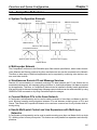
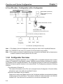
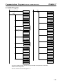
H Applicable to Various System Configurations
Remote I/O communications and message communications are available as communications functions. Normal control inputs are controlled by the remote I/O communications function. When necessary, the message communications function is used to monitor each Inverter. It is possible to control the
selection of either the communications control input or local control input provided that the Inverter software version is higher than Ver. 1042.
Note For connecting the CompoBus/D Communications Card of the Inverter, use DCA1-5C10 Thin
Cables and branch them from the T-branch Tap.
Thick Cables cannot be used for this kind of wiring because of the terminal block dimensions.
As for multi-drop wiring, use Thin Cables for direct insertion. Thick Cables cannot be used for this
kind of wiring.
C200HW-DRM21-V1 or
CVM1-DRM21-V1 (Master Unit)
Message communications function
Reading Inverter
output current
3G3FV-series Inverter
Remote I/O function
Output (PC to 3G3FV)
Wd
n
n+1
15
to
0
Inverter run commands
Rotational speed reference
Input (3G3FV to PC)
3G3FV-PDRT1-SIN
CompoBus/D
Communications Card
Note:
T-branch wiring using Thin
Cables
Switch
Run
Reverse
Forward
Stop
Power supply
Selection of either the communications
control input or local control input is
possible using Net.Ctrol./Net.Ref.
(Applicable to Inverter software higher
than Ver. 1042.)
1-4
Motor
Chapter 1
Functions and System Configuration
1-2
CompoBus/D Features
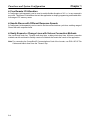
H System Configuration Example
Master by
other company OMRON Master Unit
OMRON Master Unit
OMRON Configurator
CompoBus/D Network
OMRON Configurator
OMRON Slaves
OMRON Slaves
Slaves by other company
CompoBus/D Network
Slaves by other company
Slaves by other company
OMRON Slaves
H Multi-vendor Network
The CompoBus/D conforms to the DeviceNet open field network specification, which means that devices (Masters and Slaves) produced by other manufacturers can also be connected to the Network.
Therefore, a wide range of field-level applications can be supported by combining valve devices, sensors, and other devices.
H Simultaneous Remote I/O and Message Services
Remote I/O communications to constantly exchange I/O data between the PC and Slaves can be
executed simultaneously with message communications, to send/receive Master Unit data as required
by the application. Therefore, a CompoBus/D Network can be installed to flexibly handle applications
that require both bit data and message data. Message communications can be achieved either by using
OMRON’s FINS commands or by using DeviceNet explicit messages.
H Connect Multiple PCs to the Same Network
A Configurator (sold separately) can be used to enable connection of more than one Master to the Network, allowing message communications between PCs and between multiple groups of PCs and
Slaves. This allows the CompoBus/D Network to be used as a common bus to unify controls while reducing wiring.
H Handle Multi-point Control and Line Expansions with Multi-layer
Networks
A Configurator (sold separately) can be used to enable mounting more than one Master Unit to a single
PC, allowing control of many more points. This feature can easily handle line expansions and other applications.
1-5
Functions and System Configuration
Chapter 1
H Free Remote I/O Allocation
A Configurator (sold separately) can be used to enable flexible allocation of I/O, i.e., in any area and in
any order. This allows I/O allocations that suit the application to simplify programming and enable effective usage of PC memory areas.
H Handle Slaves with Different Response Speeds
A Configurator (sold separately) can be used to set the communications cycle time, enabling usage of
Slaves with slow response times.
H Easily Expand or Change Lines with Various Connection Methods
Use a multi-drop trunk line, T-branch multi-drop lines, or daisy-chain drop lines. All three connection
methods can be combined to flexibly construct a Network that meets the needs of the application.
Note For connecting the CompoBus/D Communications Card of the Inverter, use DCA1-5C10 Thin
Cables and branch them from the T-branch Tap.
1-6
Chapter 1
Functions and System Configuration
1-3
CompoBus/D System Configuration
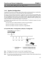
1-3-1 System Configuration
CompoBus/D is a multi-bit, multi-vendor network that combines controls and data on a machine/linecontrol level and that conforms to DeviceNet open field network specifications.
Two types of communications are supported: 1) Remote I/O communications that automatically transfer I/O between Slaves and the CPU Unit of a SYSMAC PC without any special programming in the CPU
Unit and 2) Message communications are performed between a CPU Unit to which a Master Unit is
mounted and Slaves by executing specific instructions (such as CMND and IOWR, depending on the
model of SYSMAC PC used) from the program in the CPU Unit.
A Configurator (sold separately) can be used to enable following. This allows the support of an even
larger control system.
S I/O area words can be flexibly allocated for remote I/O communications.
S More than one Master Unit can be mounted to a single PC.
S More than one Master Unit can be connected in a single Network.
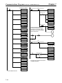
H Fixed Allocation: Configuration without a Configurator
C200HW-DRM21-V1 or CVM1-DRM21-V1
CompoBus/D Master Unit
Slave
Slave
Slave
Slave
SYSDRIVE 3G3FV
Inverter
3G3FV-PDRT1-SIN
CompoBus/D Communications Card
CV-series PCs:
C200HX/HG/HE PCs:
C200HS PCs:
64 nodes max. (including the Master Unit)
64 nodes max. (including the Master Unit)
33 nodes max. (including the Master Unit)
Note 1. The Master Unit occupies one node of the CompoBus/D Network.
Note 2. If C200HS PCs are used, only remote I/O communications are possible.
Note 3. If one node uses more than one word, the maximum number of nodes will be reduced by one
node for each extra word that is used.
1-7
Chapter 1
Functions and System Configuration
H Free Allocation: Configuration with a Configurator
C200HW-DRM21-V1 or CVM1-DRM21-V1
CompoBus/D Master Unit
Slave
Slave
3G8F5-DRM21 (ISA Board)
or
SG8E2-DRM21 (PC Card)
Configurator
SYSMAC DRIVE 3G3FV Inverter
Slave
3G3FV-PDRT1-SIN
CompoBus/D Communications Card
64 nodes max. (including the Master Unit)
Slave
Slave
Slave
Configurator
64 nodes max. (including the Master Unit)
Note 1. The Master Unit and Configurator each occupy one node of the CompoBus/D Network.
Note 2. If C200HS PCs are used, only remote I/O communications are possible.
Note 3. The maximum number of nodes that can be connected to the Network will be limited by the
maximum number of control points of the PC used.
1-3-2 Configurator Overview
The Configurator is software application run on an IBM PC/AT or compatible computer and is used to
support a CompoBus/D communications system. OMRON provides interfaces (hardware) for connecting computers to the CompoBus/D Network. The Configurator occupies one node on the CompoBus/D
Network, but has no specific functions on the network itself. The Configurator provides the following
functions.
S Free Allocation of Remote I/O
The remote I/O allocations in the PCs can be changed from the Configurator. I/O can be flexibly
allocated for each node within the specified I/O areas.
S More than One Master Unit per Network
Slaves can be set for each Master Unit from the Configurator enabling communications between
multiple groups of PCs and Slaves. The maximum number of nodes connected to one Network
remains at 64. One Slave can be connected to no more than one Master Unit.
1-8
Chapter 1
Functions and System Configuration
S More than one Master Unit per PC
Remote I/O can be allocated for each Slave of the Master Unit from the Configurator, so more
than one Master Unit can be mounted to the same PC.
Note In allocating Remote I/O for each Master Unit, be careful not to allow any dual allocation.
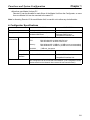
H Configurator Specifications
Item
Personal computer
Components
3G8F5-DRM21
Desktop model
Installation disk (software)
Dedicated ISA Board
Operating
Hardware
environment
Computer:
OS
CompoBus/D
interface
Relation to Network
3G8E2-DRM21
Notebook model
Installation disk (software)
Dedicated PMCIA Card
CompoBus/D Interface Unit
IBM PC/AT or compatible
CPU:
With Windows 95: 66 MHz i486 DX2 min.
With Windows NT: 90 MHz Pentium min.
Memory:
With Windows 95: 12 MB min. (16 MB or more recommended)
With Windows NT: 16 MB min. (24 MB or more recommended)
Hard disk:
5 MB min. free space
Windows 95 or Windows NT 3.51/4.0 Windows 95
Dedicated ISA Board
Dedicated PMCIA Card
CompoBus/D Interface Unit
Operates as one node on the Network, requires one node address, and only
one Configurator can be connected to the Network. (The Configurator can be
disconnected from the Network after remote I/O has been allocated.)
1-9
Chapter 1
Functions and System Configuration
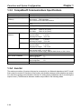
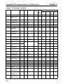
1-3-3 CompoBus/D Communications Specifications
Item
Communications protocol
Supported connections (communications)
Connection forms
Baud rate
Communications media
Communications 500 Kbps
distances
250 Kbps
125 Kbps
Communications power supply
Max. number of nodes
Max. number of Masters
Max. number of Slaves
Error control
Specifications
DeviceNet
Master-Slave: Remote I/O and explicit messages
Peer-to-peer: FINS messages
Both conform to DeviceNet specifications.
Combination of multi-drop and T-branch connections (for trunk and drop
lines)
500 Kbps, 250 Kbps, or 125 Kbps (switchable)
Special 5-wire cables (2 signal lines, 2 power lines, and 1 shield line)
Thick Cable:
DCA2-5C10 (100 m)
Thin Cable:
DCA1-5C10 (100 m)
Network length:
100 m max.
Drop line length:
6 m max.
Total drop line length: 39 m max.
Network length:
250 m max.
Drop line length:
6 m max.
Total drop line length: 78 m max.
Network length:
500 m max.
Drop line length:
6 m max.
Total drop line length: 156 m max.
24 VDC $1%, supplied externally
(Slave power supply: 11 to 25 VDC)
Recommended power supply: OMRON S82H Series or S82J Series
64 nodes
Without Configurator: 1
With Configurator:
63
Without Configurator: 63
With Configurator:
63
CRC check
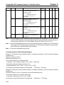
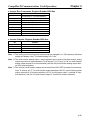
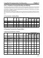
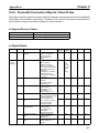
1-3-4 Inverter
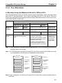
The maximum number of Inverters that can be connected to one Network depends on the PC model
that is used, the remote I/O functions of the Inverter, and whether message communications are used or
not. (Use the message communications function for setting some parameters and for monitoring the
output current.) The differences between models are provided in the following tables.
1-10
Chapter 1
Functions and System Configuration
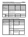
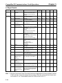
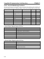
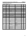
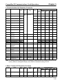
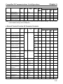
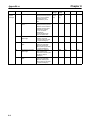
H Communications without Configurator: Fixed Allocation
Applicable PC
Master Unit
Supported communications
Max. No. of Slaves per
Master Unit
Max. No. of controlled
points per Master Unit
Allocation areas
Allocation method
CV Series
CVM1-DRM21-V1
Remote I/O and messages
Remote I/O
63
C200HX/HG/HE
C200HW-DRM21-V1
Remote I/O and messages
50
C200HS
2,048
1,600
1,024
OUT: CIO 1900 to CIO 1963
OUT: IR 050 to IR 099
OUT: IR 50 to IR 81
32
IN: CIO 2000 to CIO 2063
IN: IR 350 to IR 399
IN: IR 350 to IR 381
Words are allocated for each node to the above data areas in node address order only.
8-point Slaves: Allocated 1 word
16-point Slaves:Allocated 1 word
Max. No.
of
Inverters
Without explicit messages
With explicit
messages
Slaves with more than 16 points: Allocated multiple words
4 words remote I/O: 32
4 words remote I/O: 25 4 words remote I/O: 16
6 words remote I/O: 21
6 words remote I/O: 16
6 words remote I/O: 10
4 words remote I/O: 32
4 words remote I/O: 25
–
6 words remote I/O: 21
6 words remote I/O: 16
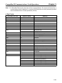
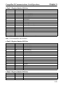
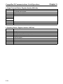
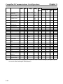
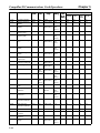
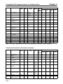
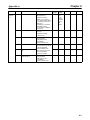
H Communications with Configurator: Free Allocation
Applicable PC
Master Unit
Supported communications
Max. No of Slaves per Master Unit
Max. No. of controlled points
per Master Unit
Allocation areas
CV-series
CVM1-DRM21-V1
Remote I/O and
messages
63
C200HX/HG/HE
C200HW-DRM21-V1
Remote I/O and messages
63
6,400 (100 words
4 blocks)
Without messages:
4,800
Core I/O Area:
CIO 0000 to
CIO 2555
CIO 0000 to
CIO 2427 for
CV500/CVM1-CPU
01(-Vj)
CPU Bus Link
Area:
G008 to G255
DM Area:
D00000 to
D24575
C200HS
Remote I/O
63
1,280 (total of 4 blocks)
With messages: 1,600
IR Area 1: IR 000 to IR 235
IR Area 2: IR 300 to IR 511
HR Area: HR 00 to HR 99
LR Area: LR 00 to LR 63
DM Area:
DM 0000 to DM 5999
DM Area:
DM 0000 to DM 5999
DM 0000 to DM 4095
D00000 to
for C200HE-CPU11 (-Z)
D08191 for
CV500/CVM1-CPU
01 (-Vj)
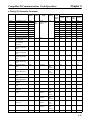
1-11
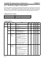
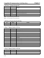
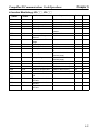
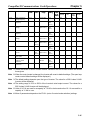
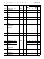
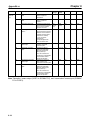
Functions and System Configuration
Applicable PC
Allocation method
Chapter 1
CV-series
C200HX/HG/HE
C200HS
Words are allocated to each node in the above data areas in any order
using the Configurator.
The following limitations apply:
The allocation areas are in 4 blocks (OUT 1, OUT 2, IN 1, and
IN 2). Each block consists of sequential words.
100 words max. per block.
For Slaves with more than 8 points, the first byte cannot be
specified in leftmost bits (7 to 15).
Words are allocated to Slaves as follows:
8-point Slaves: Allocated leftmost or rightmost byte of 1 word
16-point Slaves:Allocated 1 word
Max. No. of
Inverters
(using one
Master Unit
only)
Slaves with more than 16-points: Allocated multiple words (For Slaves
with an odd number of bytes, the last byte will be the rightmost byte)
63
4 remote I/O words: 63 4 words remote I/O: 20
6 remote I/O words: 50 6 words remote I/O: 13
Without explicit messages
With explicit
63
4 remote I/O words: 25
--messages
6 remote I/O words: 16
Max. No. Inverters with more Calculate from the number of words allocated in the data areas and the
than one Master Unit
number of words allocated to the Inverters (4 or 6 words).
Note 1. The DM Area cannot be manipulated by bit, so it cannot be allocated for remote I/O for Inverters.
Note
1-12
2. If the CPU Bus Link is used with a CV-series PC, the CPU Bus
Link Area will be used for the CPU Bus Link Therefore, the CPU
Bus Link Area cannot be allocated to Inverters if the CPU Bus
Link is used.
2
Chapter 2
CompoBus/D
Communications Line
Design
2-1
2-2
2-3
2-4
Network Configuration Overview
Network Configuration Restrictions
Communications Power Supply
Communications Line Noise Prevention
Chapter 2
CompoBus/D Communications Line Design
2-1
Network Configuration Overview
The following diagram shows the configuration of a CompoBus/D Network.
Terminating Resistors
are connected at each
end of the trunk line.
24 VDC
Trunk line
T
CompoBus/D
cables are used.
Trunk line
T
T
T-branch
Tap
T-branch
Tap
Drop line
Drop line
Drop line
Trunk line
Node
Node
Power Supply Tap
Trunk
or T-branch Tap
line
M
Terminating Resistors
are connected at each
end of the trunk line.
Trunk line M Trunk line
T
T-branch
Tap
Drop line
M
Node
Drop line
Node
CompoBus/D
cables are used.
Communications
power supply
M
T
T-branch
Tap
Drop line
Node
Node
T-branch
Tap
T-branch Tap
T
Node
Drop line
Node
M
Node
T:
T-branch connection
M: Multi-drop connection
Node
CompoBus/D cables (5-wire cables) are
used for the trunk lines and drop lines.
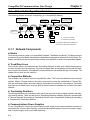
2-1-1 Network Components
H Nodes
There are two kinds of nodes on a CompoBus/D Network: The Master and Slaves. The Slaves connect
to external I/O and the Master administers the Network and manages the external I/O of the Slaves. The
Master and Slaves can be connected at any location in the Network, as shown in the preceding diagram.
H Trunk/Drop Lines
The trunk line refers to the cable that has Terminating Resistors on both ends. Cables branching from
the trunk line are known as drop lines. The trunk line length does not necessarily coincide with the maximum length of the Network. CompoBus/D communications are transmitted through 5-wire cables. The
cables come in thick and thin versions.
H Connection Methods
Two methods can be used to connect CompoBus/D nodes: The T-branch method and the multi-drop
method. With the T-branch method, the node is connected to a drop line created with a T-branch Tap.
With the multi-drop method, the node is directly connected to the trunk line or the drop line. Secondary
branches can be made from a drop line. Both of these connection methods can be used in the same
Network.
H Terminating Resistors
Terminating Resistors are connected at each end of the trunk line to reduce signal reflection and stabilize communications. There are two kinds of Terminating Resistors available: One that is provided with
a T-branch Tap and a Terminal-block Terminating Resistor. Use a CompoBus/D Cable when connecting
a Terminal-block Terminating Resistor.
H Communications Power Supplies
To use CompoBus/D, connect a communications power supply to the communications connector of
each node with a 5-wire cable. Basically, a communications power supply, internal circuit power supply,
and I/O power supply must be provided separately.
2-2
Chapter 2
CompoBus/D Communications Line Design
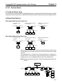
2-1-2 Connections
H Trunk and Drop Lines
The trunk line is a cable to which Terminating Resistors are connected at the ends. Drop lines are cables
that branch from the trunk lines. A special 5-wire cable is used for both the trunk lines and the drop lines.
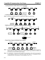
H Branching Patterns
Branching Patterns from Trunk Line
1.One drop line from
trunk line
2.Three drop lines (maximum)
from trunk line
3.Node connected directly to
trunk line
Multi-drop
Trunk line
Trunk line
Trunk line
Trunk line
Trunk line
T-branch Tap
T-branch Tap
Trunk line
Node
Drop line
T-branch Tap
Node
Node
Node
Node
Branching Patterns from Drop Line
4 One drop line from
drop line
5.Three drop lines (maximum)
from drop line
6.Node connected directly to
drop line
Multi-drop
Trunk line
Trunk line
Trunk line
Trunk line
Trunk line
T-branch Tap
T-branch Tap
Trunk line
Node
Drop line
T-branch Tap
Node
Node
Node
Node
Various forms of connection can be used on the same Network, as shown in the
following diagram. Any number of nodes up to 63 can be connected onto a single
drop line.
If a C200HX/HG/HE or a C200HS PC is being used without a Configurator to
allocate remote I/o, the maximum number of nodes that can be connected to a
single drop line is 51 for C200HX/HG/HE PCs and 33 for C200HS PCs.
Note Design the Inverter wiring for T-branch wiring purposes using Thin
Cables.
Communications
power supply
24 VDC
Trunk line
Trunk line
Power Supply Tap
Node
or T-branch Tap
Terminating
Resistor
Terminating
Resistor
Node
Drop line
Drop
line
Node
Node
Node
Node
Node
Drop
line
Node
Node
Node
2-3
Chapter 2
CompoBus/D Communications Line Design
2-2
Network Configuration Restrictions
CompoBus/D communications are designed to meet a wide range of applications by providing a choice
of baud rates and allowing different combinations of T-branch and multi-drop connections. The restrictions of CompoBus/D communications that are required to enable the various communications possibilities are described here.
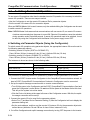
2-2-1 Baud Rate and Communications Distance
The maximum length of the CompoBus/D communications cables is restricted by the baud rate and the
type of cable used. The three types of restrictions on CompoBus/D communications cable length are as
follows:
S Maximum network length
S Drop line length
S Total drop line length
Be sure to design and configure a Network that meets the conditions provided below to ensure reliable communications.
H Maximum Communications Distance
Maximum network length
Baud rate
Thick Cable
500 kbps
250 kbps
125 kbps
100 m max.
250 m max.
500 m max.
Drop line length
Total drop line
length
Thin Cable
100 m max.
100 m max.
100 m max.
6 m max.
6 m max.
6 m max.
39 m max.
78 m max.
156 m max.
Note Thick Cable (5-wire): DCA2-5C10 (100 m)
Thin Cable (5-wire): DCA1-5C10 (100 m)
H Maximum Network Length
The length of the Network is longest at either the distance between the two most distant nodes or at the
distance between the Terminating Resistors.
There are two types of cables: Thick Cables and Thin Cables. The cable thickness affects signal deterioration. The maximum length of the Network therefore depends on the type of cable used as shown in
the previous table.
The following restrictions apply to Networks in which both Thick and Thin Cables are combined.
500 kbps
Baud rate
Maximum Network length
Thick Cable length + Thin Cable length x 100 m
250 kbps
Thick Cable length + 2.5
Thin Cable length x 250 m
125 kbps
Thick Cable length + 5.0
Thin Cable length x 500 m
H Drop Line Length
The length of the drop line is measured from the point in the trunk line where the original branch was
made to the end of the branch. The maximum length of a drop line is 6 m. It is possible to make a secondary branch from a drop line.
2-4
Chapter 2
CompoBus/D Communications Line Design
H Total Drop Line Length
The total drop line length is the total sum length of all the drop lines (but not including the trunk line). Do
not exceed the maximum total drop line length (even when the length of each individual drop line is 6 m
or less). The standard for the total drop line length varies with the baud rate as shown in the previous
table.
H Configuration Example
The following configuration example shows the maximum length of the Network, the drop line lengths,
and the total drop line length.
Trunk line
10 m
Trunk line
10 m
Trunk line
20m
Terminating
Resistor
Terminating
Resistor
2m
6m
3m
2m
Node
2m
Node
1m
Node
1m
2m
Node
1m
2m
Node
6m
6m
6m
Node
Node
Drop line
2m
Node
Node
Drop line
5m
Drop line
6m
Node
Node
Drop line
6m
Maximum Network
Length
The longest distance between nodes is 48 m, and the distance between the two
Terminating Resistors is 40 m. The maximum Network length is therefore 48 m.
Drop Line Length
There are four branch points in the trunk line. The length of each drop line is
shown in the diagram. The maximum drop line length is 6 m.
Total Drop Line Length
The sum of all the drop lines is 40 m.
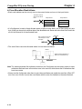
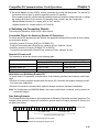
2-2-2 Locating Terminating Resistors
Be sure to connect the Terminating Resistors at both ends of the trunk line to reduce signal reflection
and stabilize communications.
When there is a T-branch Tap 6 m or less from the end of the trunk line (or the node):
A Terminating Resistor attached to a T-branch Tap can easily be mounted without taking up much
space.
When there is not a T-branch Tap 6 meters or less from the end of the trunk line (or the node):
A Terminating Resistor must be connected before that point. Either a T-branch Tap mounted to a
Terminating Resistor or a terminal block with Terminating Resistor can be used. In this case, be sure
to make the cable length 1 m or less from the node to the Terminating Resistor.
1 m or less
Truck line
Node
T-branch Tap mounted to a Terminating Resistor
or a terminal block with Terminating Resistor.
Node at end of trunk line
2-5
CompoBus/D Communications Line Design
2-3
Chapter 2
Communications Power Supply
2-3-1 Locating the Communications Power Supply
H Basic Concept
• The communications power supply must be 24 VDC.
• Make sure that the power is supplied from the trunk line.
• When providing power to several nodes from one power supply, if possible try to locate the nodes in
both directions from the power supply.
• Provide power through Power Supply Taps. It is, however, possible to use T-branch Taps instead when
there is one communications power supply in the system and the total current consumption is less
than 5 A.
• The power supply capacity for cables is restricted to 8 A for Thick Cables and 3 A for Thin Cables.
• A single Network is usually supplied by one power supply. It is, however, possible to have more than
one power supply when power supply specifications cannot be met with a single power supply. (See
2-3-4 Step 3: Splitting the System into Multiple Power Supplies.)
• Fully consider the power supply capacity allowance in the design.
• If the power supply is switched OFF during the operation of the Network, there may be a malfunction in
the nodes.
• The current capacity of the drop line varies according to its length. The longer the drop line, the lower
its maximum capacity becomes. This is the same whether the cable is thick or thin. Calculate the current capacity passing through the drop line I (the total current consumption at the drop line) using the
following formula.
I = 4.57/L
2-6
I:
L:
Permissible current (A)
Length of the drop line (m)
Chapter 2
CompoBus/D Communications Line Design
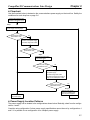
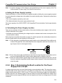
H Flowchart
Use the flowchart below to determine the communications power supply on the trunk line. Satisfy the
conditions for each drop line on page 2-6.
Provisionally determine the
location of the power supply.
Step 1
Determine the best location of the
power supply from the graphs.
Are the power supply
specifications met?
Yes
No
Consider changing the
location of the power supply.
Consider using Thick Cable.
Are the power supply
specifications met?
No
Step 2
Yes
Calculate the best location
of the actual nodes.
Are the power supply
specifications met?
Yes
No
Consider changing the location of
the power supply.
Consider using Thick Cable.
Consider changing the location of
high current consumption nodes.
Are the power supply
specifications met?
No
Step 3
Yes
Split the power supply
system by installing more
than two power supplies.
Set the location for
the power supply.
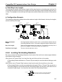
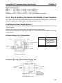
H Power Supply Location Patterns
The power supply can be located in the configurations shown below. Basically, select from the configurations 1 and 2.
Consider using configuration 3 when power supply specifications cannot be met by configurations 1
and 2. It is possible to use configuration 4 for a duplex power supply.
2-7
Chapter 2
CompoBus/D Communications Line Design
1 Locating the Nodes on Both Sides of the Power Supply
Power Supply Tap
or T-branch Tap
Node
Node
Communications
power supply
Node
Node
Node
2 Locating the Nodes on One Side of the Power Supply
Note Configuration 1 is recommended for a single power supply to several nodes.
Power Supply Tap
or T-branch Tap
Communications
power supply
Node
Node
Node
Node
Node
3 Splitting the Power Supply System with Multiple Power Supplies
System 1
System 2
Special Power Supply Tap
Communications
power supply
Special Power Supply Tap
Node
Node
Communications
power supply
Node
Node
Node
Remove the fuse
and split +V.
fuse
V+
Make –V the same for
Systems 1 and 2.
V–
24 V
0V
4 Duplex Power Supply with Multiple Power Supplies
Special Power
Supply Tap
Communications
power supply
Special Power
Supply Tap
Node
Node
Node
Node
Node
Communications
power supply
Note 1. If power supply specifications cannot be met with a single power supply when the current capacity of the Thick Cable exceeds 8 A even after the power supply location is modified, use
more than one communications power supply.
Note 2. In configuration 1, the power can be supplied in two directions to the trunk line as long as the
current capacity of each is 8 A or less when using Thick Cable, i.e., it is possible to have a
configuration with a total maximum current capacity of up to 16 A.
2-8
Chapter 2
CompoBus/D Communications Line Design
Note 3. Consider changing to Thick Cable to meet specifications if the current capacity of the Thin
Cable exceeds 3 A when using Thin Cable for the trunk line.
H Setting the Power Supply Location
Determine whether or not the current can be supplied normally by finding the current capacity required
by each node and the voltage drop in the cables to be used to provide power. Calculate the values below
in advance.
• The current capacity required by each node
• The distance between the power supply and each node
The current capacity of the 3G3FV-PDRT1-SIN CompoBus/D Communications Card is approximately
20 mA.
H Calculating the Power Supply Location
There are two methods to find the best location of the communications power supply on the trunk line.
• Simple calculation from a graph
• Calculation by formula (Calculating the voltage drop from resistance and current consumption of the
communications cables).
Each drop line must satisfy the equation on page 2-6, which represents the relationship between the
drop line length and the current capacity for the drop line.
Note 1. From the graph, a hypothetical power supply location can be determined if the conditions calculated in the graph are met by estimating the worst configuration (that has the maximum voltage drop as shown in the diagram below).
Node
Node
Node
Communications
power supply
Node
Note 2. Even if the power supply specifications cannot be met using the graph, the conditions can be
met and a hypothetical power supply location determined by using the formula.
Note 3. When the communications power supply and the internal circuit supply are the same, use the
formula to calculate a hypothetical power supply location because it cannot be determined by
using the graph.
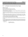
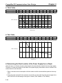
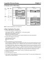
2-3-2 Step 1: Determining the Best Location for the Power
Supply from a Graph
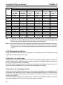
A voltage drop occurs when a current flows through a communications cable. The longer the communications cable and the larger the current, the greater the voltage drop. The communications power
supply at each node must be 11 VDC or more. To ensure the correct power supply, the relationship is
plotted as shown in the following graph to find the maximum current that satisfies the voltage of the
communications power supply at different trunk line lengths even if there is a voltage drop due to cable
resistance.
2-9
Chapter 2
CompoBus/D Communications Line Design
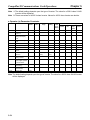
H Thick Cable
Distance (m)
Max. current (A)
0
8.00
25
8.00
50
5.42
100
2.93
150
2.01
200
1.53
250
1.23
300
1.03
350
0.89
400
0.78
450
0.69
500
0.63
8
7
6
Max. current (A)
5
4
3
2
1
0
0
Distance (m)
H Thin Cable
Distance (m)
Max. current (A)
0
3.00
10
3.00
20
3.00
30
2.06
40
1.57
50
1.26
60
1.06
70
0.91
80
0.80
90
0.71
100
0.64
3
2
Max. current (A)
1
0
0
Distance (m)
H Determining the Best Location of the Power Supply from a Graph
Verify the Items 1 to 3 below for each node located in the same direction viewed from the power supply.
Therefore, if nodes are located on both sides of the power supply, these items must be verified for all
nodes located in each direction.
1 Find A, the total current consumption of all the nodes to which communications power is to be supplied.
2 Using the graph compute B, the maximum current flow in each cable from the power supply to the
end of the trunk line according to the types of cables (Thick Cables or Thin Cables).
2-10
Chapter 2
CompoBus/D Communications Line Design
3 Compare the values found in steps 1 and 2, above. If the first value (A) is less than the second (B),
this shows that power supply specifications are met and power can be supplied to all nodes at any
point in the Network.
Note Be sure to refer to the correct graph as the maximum current flow is different for Thick and Thin
Cables.
H Countermeasures
If the second value (B) is less than the first (A), use the following procedure to locate the communications power supply.
• Locate the communications power supply in the center of the Network and the nodes to both sides of it.
• If the nodes are already located at both sides of the power supply, move the power supply in the direction that requires the larger current capacity.
• If Thin Cable is being used, replace it with Thick Cable.
Note If, after following the above procedure, B is still less than A, go to Step 2 and determine the actual
position of the nodes by the formula calculation method.
D Calculation Example
The following example shows a Network that requires power to be supplied for 240 m on Thick Cable.
The power supply is located in the center of the Network. Because the power supply is in the center, the
maximum current will flow both to the left and to the right, enabling the supply of at least twice the maximum current as when the power supply is placed on the end of the Network. The current consumption
for individual nodes is as follows:
Terminating Resistor
Trunk line
(5-wire cable)
Trunk line
(5-wire cable)
Terminating Resistor
3 m max.
Node
Node
0.1 A
0.25 A
Node
0.2 A
Communications
power supply
Node
Node
Node
0.15 A
0.25 A
0.15 A
120 m
120 m
Trunk line
Power supply cable
Total power supply length on left = Total power supply length on right = 120 m
Total current consumption on left: 0.1 + 0.25 + 0.2 = 0.55 A
Total current consumption on right: 0.15 + 0.25 + 0.15 = 0.55 A
Maximum current for the left side of the Thick Cable (see previous table) = approx. 2.5 A
Maximum current for the right side of the Thick Cable (see previous table) = approx. 2.5 A
(using straight line approximation between 100 to 150 m)
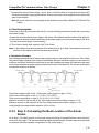
2-3-3 Step 2: Calculating the Best Location of the Actual
Nodes
Go to Step 2 if the best location for the power supply according to the specifications cannot be determined from the graphs. The second method calculates the best location for each actual node and does
not estimate the worst possible configuration for the power supply.
2-11
Chapter 2
CompoBus/D Communications Line Design
Basically, in the CompoBus/D Network the permissible maximum voltage drop within the system can be
specified at 5 V for a power supply line (+V or –V), by calculating the specifications for the voltage of the
communications power supply (24 VDC) and the input voltage of the communications power supply of
each device (11 to 25 VDC).
Of the permissible 5-V maximum voltage drop within the system, the permissible voltage drop is 4.65 V
in the trunk lines and 0.35 V in the drop lines.
The following formulae are applicable when power is supplied independently for communications
and the internal circuit. For details on voltage drop and formulae when the communications power
supply and internal circuit power supply are shared, refer to the CompoBus/D (DeviceNet) Operation Manual.
H Formulae
Try to calculate the best location for each node using the formula below. If the best location for each
node can be determined using the formula, the specifications for the power supply to each node can
also be met. Do not exceed the maximum current capacity of the cable (Thick Cable: 8 A and Thin
Cable: 3 A).
{(L1 × RC + N1 × 0.005) × l1} + {(L2 × RC + N2 × 0.005) × l2} + ..... + {(Ln × RC + Nn × 0.005) × ln} x 4.65 V
Li:
The distance (m) of the trunk line between the power supply and node i.
Rc:
Maximum cable resistance for approx. 1 m
(Thick Cable: 0.015 Ω/m, Thin Cable: 0.069 Ω/m)
Ni:
The number of T-branch Taps on the trunk line between the power supply and node i.
Ii:
The consumption current required for the communications power supply for node i.
0.005 Ω = The contact resistance of the T-branch Taps.
Note If there are nodes on both sides of the power supply, the formula is used to calculate the best
location in each direction, and if the conditions are satisfied, then the locations are valid. The
conditions are satisfied if the following equations are true.
Voltage drop (V) on trunk line at left side x 4.65 V
Voltage drop (V) on trunk line at right side x 4.65 V
D Calculation Example
Terminating Resistor
Trunk line
(5-wire cable)
Trunk line
(5-wire cable)
Terminating Resistor
3m
max.
Node
Node
Node
0.1 A
0.25 A
0.2 A
40 m
40 m
Communications
power supply
40 m
40 m
Node
Node
Node
0.15 A
0.25 A
0.15 A
40 m
40 m
Left Side Equation
Node 1:
(120 0.015 + 3
0.005)
0.1 = 0.1815 (V)
Node 2:
(80 0.015 + 2
0.005)
0.25 = 0.3025 (V)
Node 3:
(40 0.015 + 1
0.005)
0.2 = 0.121 (V)
If 0.1815 + 0.3025 + 0.121 = 0.605 V x 4.65 V, the conditions are satisfied.
2-12
Chapter 2
CompoBus/D Communications Line Design
Right Side Calculation
Node 4:
(40 0.015 + 1
0.005)
0.15 = 0.09075 (V)
Node 5:
(80 0.015 + 2
0.005)
0.25 = 0.3025 (V)
Node 6:
(120 0.015 + 3
0.005)
0.15 = 0.27225 (V)
If 0.09075 + 0.3025 + 0.27225 = 0.6655 V x 4.65 V, the conditions are satisfied.
2-3-4 Step 3: Splitting the System into Multiple Power Supplies
Go to Step 3 if the best location for the nodes cannot be calculated from the formulae. In the third step,
there are multiple power supplies and the power supply system is split.
H Splitting the Power Supply System
• Be sure to use a Power Supply Tap for each power supply when the Network is supplied by two or more
power supplies.
• Remove the fuses in the Power Supply Tap to split the power supply system.
Once the power supply system is split, return to Step 1 or 2, and determine the best location of the nodes
in each system.
H Power Supply Tap Configuration
Connector C
Model
Specification
Fuse B
Fuse A
Power supply cable
Cable A
1485T-R2T5-T5
Power supply tap
(with a grounding
terminal and reverse
current prevention
function )
Manufacturer Allen-Bradley
Cable B
Connector A
Connector B
H Internal Circuitry of the Power Supply Tap
Power Supply Tap
V+
5-wire cables
on side A
Fuse A
Fuse B
V+
CAN H
CAN H
Shield
Shield
CAN L
CAN L
V–
5-wire cables
on side B
V–
Schottky
diode
Ground V–
terminal
V+
Fuses used:
Littel fuse 312008
Rated amperage: 8 A
Rated voltage: 250 V
6.35 Φ x 31.75 mm
Power supply device on side C
2-13
CompoBus/D Communications Line Design
Chapter 2
2-3-5 Dual Power Supplies
Because diodes are contained in Power Supply Taps, these taps can be used to construct a dual power
supply system in the Network. Dual power supply differs from parallel operation of power supplies, so
the following restrictions apply.
H Restrictions
Dual power supply is basically used to ensure backup power supply, not parallel operation of power
supplies. Therefore, each power supply to be used must meet the power allocation specifications (i.e.,
must satisfy steps 1 and 2).
2-14
Chapter 2
CompoBus/D Communications Line Design
2-4
Communications Line Noise Prevention
2-4-1 Communications Line Noise
The communications line sends and receives high-speed pulse signals, and checks whether the data is
correct by checking the sequence of the signals. If the amount of noise on the communications line is too
great, the interference will alter the communications signal data, and communications will be impossible. Communications lines are more sensitive and require higher speeds than normal I/O lines, so be
sure that noise does not interfere with communications. Use the preventative noise countermeasures
described here when configuring the system to ensure smooth system start up.
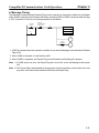
2-4-2 Grounding the Network
H Grounding the Network
The CompoBus/D Network must be grounded at only one location so that a ground loop is not created.
The ground should also be connected as close as possible to the center of the Network. Connect the
cable shield to the ground terminal on the communications power supply and then connect to a ground
of 100 Ω max., as shown in the following diagram.
Power Supply Tap
V+
V+
CAN H
Shield
CAN H
CAN L
CAN L
V–
Shield
V–
Ground
terminal
V–
Communications
cable
V+
FG V– V+
Communications
power supply
Ground (100 Ω max.)
If more than one communications power supply is connected to the same Network, ground only the one
nearest the center of the Network. Do not connect the shield wire at the other power supplies.
Note 1. Always ground the communications cable shield at one and only one location in the Network.
Note 2. Always ground to 100 Ω or less.
Note 3. Always use a separate ground. Never use the same ground as for Inverters or other drive
system devices.
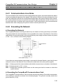
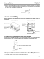
H Grounding the CompoBus/D Communications Card
The CompoBus/D Communications Card should be grounded according to DeviceNet recommendations installing a noise filter as shown in the following diagram. The ground is normally wired to the
ground terminal (12 (G)).
2-15
Chapter 2
CompoBus/D Communications Line Design
Note If the cable grounded to the Inverter is not sufficient and is receiving noise interference, disconnect the grounding cable.
Shield
2-4-3 Communications Power Supply Noise Prevention
The communications power supply is the most important power supply in a CompoBus/D Network. The
following measures will prevent noise in the communications power supply.
• Use the recommended power supply (S82H/S82J) for communications.
• Use an independent power supply for communications.
• Make sure to install a noise filter on the primary AC input side of the communications power supply.
• Always use a control system power supply for the primary AC side of the communications power supply that is not shared with power devices, such as Inverters or motors.
If noise interference remains in cables for which noise countermeasures have been implemented, the
following countermeasures may be effective.
D Communications Cable Shielding
Suspend the communications cable shielding wire without grounding it. This will filter the noise that
flows from the ground to the communications cable and will filter the noise current that flows in the
shielding wire.
D Communications Power Supply
Suspend the communications power supply without grounding it. This will also filter the noise that flows
from the communications power supply ground to the communications cable or the noise current that
flows in the shielding wire. The switching power supply is usually connected to the case and the capacitor as shown below. The ground (FG) terminal must be suspended and the control panel for the power
supply itself must be insulated.
Switching Power Supply Configuration
Switching power supply
AC power supply
AC input
Power
supply
circuit
DC output
Casing
2-16
Chapter 2
CompoBus/D Communications Line Design
Suspending the Communications Power Supply
S82J power supply
DC power supply
Insulating material (such as
baked board or acrylic board)
S82Y-jjN (Mounting Tool)
When using S82J power supply
When using other power supplies
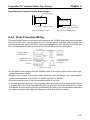
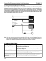
2-4-4 Noise Prevention Wiring
To prevent inductive noise, do not wire the communications line, SYSMAC power lines, and other power
lines near to each other. Keep the power lines for Inverters, motors, regulators, and contactors, the
communications lines, and the SYSMAC power lines separated from each other by at least 300 mm.
Also, provide separate conduits or ducts for the communications lines and power lines.
Low-voltage cable
Communications cable
Suspended duct
Floor duct
Communications line
SYSMAC I/O Line
Control cable
300 mm
max.
Power cable
300 mm
max.
SYSMAC Power Line
General control circuit line
Shielding
Communications line
SYSMAC I/O Line
Power line
Power line
Ground (100 Ω max.)
• Do not install communications lines and SYSMAC power lines onto the control panel on which highvoltage devices are mounted.
• Because noise currents flow through metallic equipment (such as casings), the communications
cables should be placed as far away from metallic equipment as possible.
• Ground the shielding wire on the communications cable at one point.
• If the same ground is used for the communications cables and communications power supply, there is
a possibility that noise may be transmitted through the ground line to the communications line. In order
to avoid this, be sure that the power line ground and the grounds for the communications cables and
the communications power supply are located as far from each other as possible.
2-17
Chapter 2
CompoBus/D Communications Line Design
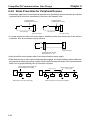
2-4-5 Noise Prevention for Peripheral Devices
• Install surge suppressors on devices that generate noise, particularly devices that have an inductive
component such as motors, transformers, solenoids, and magnetic coils.
Surge suppressor
(Installed next to device)
DC input type
Surge suppressor
(Installed next to device)
Device
(such as a motor)
AC input type
Device
(such as a motor)
• If a surge suppressor does not fit on the device, installing a ferrite core directly next to the device’s
contactors, such as a contactor may be effective.
Device
(such as a motor)
Ferrite core 0443-1641151
Nisshin Electric Co, Ltd.
• Insert a line filter on the primary side of the communications power supply.
• When there are two or more communications power supplies, the communications power cables can
be grounded by simply connecting a single Power Supply Tap near the center of the communications
cable. Do not ground shielding wire at more than one place.
T-branch Tap or Power Supply Tap
or Communications Connector
Ground at only one point
Power Supply Tap
Master
Master
PS
Slave
Slave
When there is only one power supply
2-18
Power Supply Tap
PS
Slave
PS
Slave
When there are two or more power supplies
PS
3
Chapter 3
Setup and Wiring
3-1
3-2
Nomenclature and Settings
Installation and Wiring
Chapter 3
Setup and Wiring
3-1
Nomenclature and Settings
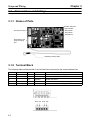
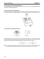
3-1-1 Names of Parts
Operation indicators
PWR indicator
MS indicator
Terminal block (TC)
NS indicator
WD indicator
Node address and
baud rate setting
pins
Shielded grounding cable
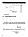
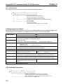
3-1-2 Terminal Block
The following table provides details of the terminal block connected to the communications line.
Display
1
2
3
4
5
Sticker color
Black
Blue
--White
Red
Code
V–
CAN L
SG
CAN H
V+
Cable color
Black
Blue
(Shield)
White
Red
Details
Communications power supply ground.
Communications data low side.
Shield connection.
Communications data high side.
Communications power supply, 24 VDC.
Black Blue White Red
3-2
Chapter 3
Setup and Wiring
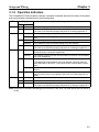
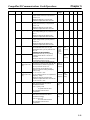
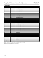
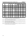
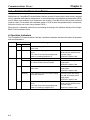
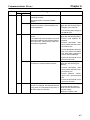
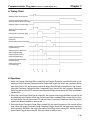
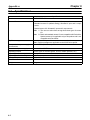
3-1-3 Operation Indicators
The CompoBus/D Communications Card has 4 operation indicators that show the status of the power
and communications as described in the following table.
Display
Indicator
PWR
MS
Color
Status
Green Lit
--Not lit
Green Lit
Flashing
Red
---
NS
Lit
Flashing
Not lit
Green Lit
Flashing
Red
Lit
Flashing
---
WD
Not lit
Green Flashing
Red
Lit
--Not lit
Meaning
Power is being supplied from the Inverter to the Card.
Power is not being supplied from the Inverter.
The Card is not connected properly and power is not being supplied to it.
The Card is operating normally.
Initial settings or necessary preparations for communications are incomplete.
A fatal error (hardware error) has occurred in the Card.
A non-fatal error, such as a switch setting error, has occurred.
Power is not being supplied from the Inverter.
The Card is not connected properly and power is not being to supplied to it.
The CompoBus/D Network (DeviceNet) is operating normally.
(Communications connection established.)
The Network is normal, but the communications connection with the Master
Unit is not established.
A fatal communications error has occurred.
A CompoBus/D communications error was detected caused by node address duplication or Bus OFF. (These errors make communications impossible.)
A non-fatal communications error has occurred due to communications
timeout.
A CompoBus/D Network error has occurred. For example, the Network
does not exist, power is not supplied to the Card, or the baud rates do not
match.
The CPU Unit of the Card is operating normally.
The CPU Unit of the Card is not ready or the CPU Unit has malfunctioned.
Power is not being supplied from the Inverter.
The Card is not connected properly and power is not being to supplied to it.
Note When both of the baud rate setting pins DR0 and DR1 are set to ON, both the MS and NS will be lit
in red.
3-3
Chapter 3
Setup and Wiring
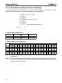
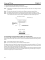
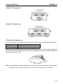
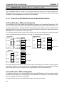
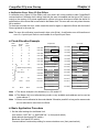
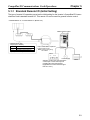
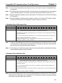
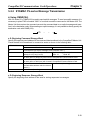
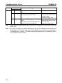
3-1-4 Baud Rate and Node Address Settings
In a CompoBus/D Network, the baud rate can be set to 500 Kbps, 250 Kbps, or 125 Kbps. To manage
Master/Slave communications, numbers are assigned as node addresses.
Baud rate setting pins
Node address setting pins
Note Default settings are all OFF.
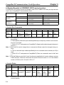
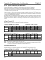
H Baud Rate Setting Pins
Pin
500 Kbps
ON
OFF
DR1
DR0
250 Kbps
OFF
ON
125 Kbps
OFF
OFF
H Node Address Setting Pins
Node Address
Pin
0
1
2
3
4
5
6
7
8
9
10
11
12
13
14
15
ADR5
OFF
OFF
OFF
OFF
OFF
OFF
OFF
OFF
OFF
OFF
OFF
OFF
OFF
OFF
OFF
OFF
to
to
ON
63
ADR4
OFF
OFF
OFF
OFF
OFF
OFF
OFF
OFF
OFF
OFF
OFF
OFF
OFF
OFF
OFF
OFF
to
ON
ADR3
OFF
OFF
OFF
OFF
OFF
OFF
OFF
OFF
ON
ON
ON
ON
ON
ON
ON
ON
to
ON
ADR2
OFF
OFF
OFF
OFF
ON
ON
ON
ON
OFF
OFF
OFF
OFF
ON
ON
ON
ON
to
ON
ADR1
OFF
OFF
ON
ON
OFF
OFF
ON
ON
OFF
OFF
ON
ON
OFF
OFF
ON
ON
to
ON
ADR0
OFF
ON
OFF
ON
OFF
ON
OFF
ON
OFF
ON
OFF
ON
OFF
ON
OFF
ON
to
ON
Note 1. The same node address cannot be used for more than one Slave connected to the communications line.
Note 2. Remote I/O allocations in the CPU Unit are affected by the node addresses, so make sure that
the remote I/O allocations do not overlap before setting a node address. Refer to Chapter 4
CompoBus/D System Startup.
3-4
Setup and Wiring
3-2
Chapter 3
Installation and Wiring
!
WARNING
Never touch any internal parts of the Inverter. Doing so may result in electric shock.
!
WARNING
Install, remove, or wire the Optional Card only after turning OFF the Inverter, making
sure that all the indicators of the Inverter are OFF, and waiting for the time specified
on the front cover of the Inverter to elapse. Not doing so may result in electric shock.
!
WARNING
Do not damage, press, or put excessive stress or heavy objects on the cables. Doing
so may result in electric shock, product malfunction, or product damage.
! Caution
Do not touch the parts of the Optional Card by hand. Otherwise, static electricity may
damage the Optional Card.
! Caution
Be sure that the connector of the Optional Card is firmly in place on the Inverter. Improper connection may cause injury, product malfunction, or product damage.
3-2-1 CompoBus/D Communications Card Installation
! Caution
Before installing and wiring an Optional Card, always turn OFF the power to the
SYSDRIVE 3G3FV Inverter and wait for the CHARGE indicator to turn OFF.
H Mounting Procedure
1. Turn OFF the Inverter, wait for at least one minute (or at least three minutes if the Inverter has an
output capacity of 30 kW or more), remove the front cover of the Inverter, and check that the
CHARGE indicator is not lit.
2. Mount the Optional Card to the option C area.
3. Insert the provided spacers into the spacer holes on the mounting base of the Inverter.
4. After properly engaging the connectors of the Optional Card and control circuit board, insert the
spacers to the spacer holes of the Optional Card, and press the Optional Card until the spacers
click.
5. Connect the shielded ground cable of the Optional Card to FG terminal 12 (E) on the control circuit
board of the Inverter.
3-5
Chapter 3
Setup and Wiring
6. Press the top of the connector 2CN and check that the apexes of the triangular marks on both sides
match.
Option A
Control
Circuit
Board
Connector
4CN for
option A area
Make sure that the
apexes of the black
triangular marks match
Option C
Connector
2CN for
option C area
Connector
3CN for
option D area
Front View
Side View
Note When the CompoBus/D Communications Card is mounted, other Optional Cards cannot be
mounted in the C area.
3-2-2 Communications Cable Wiring
H Connecting Communications Cables
This section explains how to prepare and connect the communications cables to connectors for the
CompoBus/D Network.
Use the following procedure to prepare and connect the communications cables to the connectors.
Note For connecting of the CompoBus/D Communications Card of the Inverter, use DCA1-5C10 Thin
Cables.
Thick Cables cannot be used for this kind of wiring because of the terminal block dimensions.
1. Remove about 30 mm of the cable covering, being careful not to damage the shield weaving underneath. Do not remove more than about 30 mm; removing too much of the covering can result in short
circuits.
About 30 mm
2. Carefully peel back the weaving to reveal the signal lines, power lines, and the shielding wire. The
shielding wire will be loose on the outside of the other lines, but it is harder than the weaving.
Shielding wire
3-6
Chapter 3
Setup and Wiring
3. Remove the exposed weaving and the aluminum tape from the signal and power lines. Strip the
covering from the signal and power lines to the proper length for the crimp terminals. Twist together
the wires of each of the signal and power lines.
Strip to match the crimp terminals
H Inverter Internal Wiring
Keep the CompoBus/D wiring separated from the main circuit wiring as much as possible. Do not wire
them together.
Inverters of 15 kW or Less
Inverters of 18.5 kW or More
CompoBus/D
communications
line wiring
Side panel of Inverter
CompoBus/D
Communications
Card
Operator
Pass the CompoBus/D
communications line
wiring by breaking off
this portion.
Control wiring
Main circuit wiring
Do not bundle the control wiring and
main circuit wiring together.
H CompoBus/D Communications Card Crimp Terminal
To further improve the reliability and ease of wiring, use the following straight crimp terminal when wiring
the communications cable to the terminal block of the CompoBus/D Communications Card.
1.0 dia.
Model: A1 0.5–8 WH (by Phoenix Contact)
2.6 dia.
Unit: mm
H CompoBus/D Communications Card Terminal Block Wiring Procedure
1. Loosen the terminal screws using a thin flat-blade screwdriver.
3-7
Chapter 3
Setup and Wiring
2. Insert the wires from underneath the terminal block.
3. Tighten the terminal screws securely to a torque of 0.5 N@m.
Note 1. Separate the CompoBus/D communications cables from the main circuit wiring and other
power lines.
Note 2. Do not solder the ends of the electric wires. Doing so may cause contact failure.
Note 3. If straight crimp terminals are not used, strip the electrical wires to a length of 5.5 mm.
Note 4. Do not tighten the screws to a torque exceeding 0.5 N@m. Doing so may damage the terminal
block. If the screws are too loose, however, malfunctions or short circuits may result.
Thin flat-blade screwdriver
Terminal block (TC)
Strip to 5.5 mm
(if straight crimp
terminal is not
used).
Wire
Straight crimp terminal
or unsoldered cable
Black Blue White Red
H Connecting Communications Cables to T-branch Taps
For connecting the CompoBus/D Communications Card, use DCA1-5C10 Thin Cables and branch
them from the T-branch Tap. This is done for reasons of terminal block dimensions and easy maintenance.
Note 1. Thick Cables cannot be used for this wiring.
Note 2. As for multi-drop wiring, use Thin Cables for direct insertion.
This section shows how to connect a communications cable with a connector attached to a T-branch
Tap. There are two kinds of T-branch Taps, one makes a single branch and the other makes three
branches, but the cable connections are the same for both.
The connectors indicated by asterisks in the following diagrams have the least resistance and these
connectors should be used for the trunk line connections. When using a T-branch Tap on a drop line,
connect the longest drop line to these connectors.
3-8
Chapter 3
Setup and Wiring
D DCN1-1C T-branch Tap
* Use for trunk line of
longest drop line.
D DCN1-3C T-branch Tap
* Use for trunk line of
longest drop line.
D T-branch Tap Connectors
The required number of connectors (on cable side) for T-branch Taps are supplied with the product.
Name
Model
Manufacturer
COMBICON Plug with Screw Flange
MSTBP 2515-STF-5.08 AB AU SO
Phoenix Contact
Align the cable connector with the socket on the T-branch Tap as shown in the following diagram and
fully insert the connector into the socket. Tighten the set screws to secure the connection. Tighten the
screws to a torque of 0.3 N@m.
Note To avoid damaging the cable or breaking wires, do not pull on the cable or bend it too sharply when
connecting it to the T-branch Tap. Also, never place heavy objects on top of the cable.
3-9
Chapter 3
Setup and Wiring
H Connecting Terminating Resistors
Terminating resistors must be connected at each end of the trunk line. Use the methods described here
to connect the Terminating Resistors.
D T-branch Tap Terminating Resistor
A Terminating Resistor is included with the T-branch Tap. Insert the Terminating Resistor into the Tbranch Tap as shown in the following diagram. The Terminating Resistor can face in either direction.
21 max.
D Terminal-block Terminating Resistor
20
41 max.
20 max.
A Terminating Resistor is built into the Terminal-block Terminating Resistor. To connect the cable to the
Terminating Resistor, attach standard M3 crimp terminals to the signal wires and securely screw the
terminals to the Terminal-block Terminating Resistor. Tighten to a torque of 0.5 N@m.
6.0 mm max.
6.0 mm max.
Note To avoid damaging the cable or breaking wires, do not pull on the cable or bend it too sharply when
connecting it to the terminal block. Also, never place heavy objects on top of the cable.
3-10
4
Chapter 4
CompoBus/D System
Startup
4-1
4-2
4-3
SYSMAC Word Allocations and Scan List
SYSDRIVE 3G3FV Settings
Startup Procedure
Chapter 4
CompoBus/D System Startup
4-1
SYSMAC Word Allocations and Scan List
In a CompoBus/D Network, remote I/O and message communications can be used simultaneously.
This section describes remote I/O communications, particularly the memory words allocated in the
SYSMAC PC that correspond to the remote I/O of the Slaves.
4-1-1 Overview and Restrictions of Word Allocations
H Fixed Allocation: Without Configurator
If a Configurator is not used, default word allocations are used in the CompoBus/D Master Unit. The
remote I/O is allocated in the order of CompoBus/D node addresses and the words are divided into output areas and input areas. The word allocation default settings of the Master Unit are set based on the
assumption that one node should occupy one input word and one output word. Output words will be
allocated even to Units that are used only for input.
For Units that require two input words or two output words, the node addresses to which the second
word is normally allocated cannot be set. If it is set, the word allocations will overlap.
C200HX/HG/HE PCs
CV-series PCs
CIO 1900
CIO 1963
CIO 2000
Output
area
Input
area
CIO 2063
IR 50
CIO 1900
CIO 1901
Node 0
Node 1
CIO 1962
CIO 1963
Node 62
Node 63
IR 99
CIO 2000
CIO 2001
Node 0
Node 1
IR 350
CIO 2064
CIO 2063
Node 62
Node 63
IR 50
IR 51
Node 0
Node 1
IR 80
IR 81
Node 62
Node 63
IR 350
IR 351
Node 0
Node 1
IR 380
IR 381
Node 62
Node 63
To Slaves
From Slaves
IR 399
Output
area
Input
area
IR 50
IR 51
Node 0
Node 1
IR 98
IR 99
Node 62
Node 63
IR 350
IR 351
Node 0
Node 1
IR 398
IR 399
Node 62
Node 63
To Slaves
From Slaves
C200HS PCs
IR 50
IR 81
IR 350
IR 381
Output
area
Input
area
To Slaves
From Slaves
Each node address is allocated one input and one output word starting from node 00. If a Slave requires
more than one input or one output word, then it is assigned more than one node address. If a Slave
requires less than one word, it simply uses the rightmost bits in the word allocated to it.
H Free Allocation: With Configurator
A Configurator can be used to allocate words in the CompoBus/D Master Unit in any order by calling
parameters of the Master Unit and changing the word allocation of parameters. The following allocations are possible when using a Configurator.
• Output words do not need to be allocated to Input Units, only input words.
4-2
Chapter 4
CompoBus/D System Startup
• Slaves that require two words can be allocated two words using only one node address so that the next
node addresses can be set for another Slave.
• Remote I/O words can be allocated in sequence regardless of the order of the node addresses.
Note The Configurator uses one node address. Therefore, the number of Slaves that can be connected
is reduced if the Network is to be operated with the Configurator still connected. The Configurator
can be removed, however, after the words have been allocated, and then another Slave can be
connected to the Network in its place so that the number of Slaves that can be connected is not
reduced.
Blocks can be positioned in any order in memory,
e.g., the following order is okay: input block 1, output block 2, input block 2, output block 1.
CPU Unit
Address
Output area
Output
block 1
Output
block 2
Address
Address
Address
Input area
To Slaves
Input
block 1
Address
Input
block 2
Address
Addresses can be assigned in any order
From Slaves
Address
Address
Words are freely allocated to the Slaves and I/O blocks can be set as desired. Each node must be allocated at least one byte (leftmost or rightmost). If a Slave requires more than one input or one output
word, then it can be allocated more than one input or output word. If a Slave requires less than one word,
it will use either the rightmost or leftmost bits in the word allocated to it.
D Free Allocation Restrictions
The following restrictions apply when freely allocating remote I/O.
• The remote I/O allocated to one Slave cannot be separated, i.e., all input words must be consecutive,
as must all output words. Inputs and outputs, however, can be separated.
• With a Slave requiring more than one word, a series of allocations cannot be started from the leftmost
byte of the remote I/O. The leftmost byte, however, can be allocated to a Slave requiring only 8 bits.
• Multiple words cannot be allocated as the remote I/O for a single Slave.
• A Slave cannot be assigned to more than one Master Unit.
4-1-2 Scan Lists
H The Scan List
Scan lists record information in the Master Unit on the Slaves that are connected to them. If the scan list
is enabled, the information on each Slave is recorded, and can be used to determine normal CompoBus/D communications. The scan list provides the following information on each Slave.
4-3
Chapter 4
CompoBus/D System Startup
• Slave remote I/O allocations providing the number of I/O words allocated to and the node address set
for each Slave.
• Communications parameters providing the initial remote I/O communications status and the communications cycle time settings.
H Scan List Application
A scan list is not required for a Network with only one Master Unit and remote I/O that is allocated according to the fixed settings. The scan list is necessary, however, in the following cases.
• To confirm the increase or decrease of Slaves on the communications line, and to detect errors in a
Network where the number of Slaves has increased or decreased, it is necessary to record the system
status.
• For free allocation of remote I/O, it is necessary to record the number of I/O words allocated to each
Slave.
• When using multiple Master Units to exchange information with the SYSMAC PC (CPU Unit), it is necessary for each Master Unit to record the node addresses for each Slave.
H Creating Scan Lists
D Fixed Remote I/O Allocations
A scan list can be created by turning ON the Enable Scan List software switch when the CPU Unit is in
PROGRAM mode, when communications are active and the scan list is disabled. All Slaves that are
participating normally in the Network will be registered in the scan list.
D Free Remote I/O Allocations
The user creates the scan list using the Configurator and then registers it in the Master Unit. Settings for
all Masters and Slaves participating normally in the Network are used as a basis for creating the scan
list.
Scan list enabled
Fixed allocations
Scan list disabled
Remote I/O communications
Free allocations
Scan list enabled
Scan List Disabled
Scan List Enabled
Registered using
software switch.
Scan list
Fixed allocations
All Slaves participating
normally in the Network.
Fixed allocations
All Slaves.
Slave I/O allocations
Communications parameters
Free allocations
Registered as scan
list in the Master Unit.
Set as required using
the Configurator.
Note The scan lists created with the Configurator will be required again for registration in the Master
Unit if the Master Unit is ever set to disable the scan list or if the Master Unit is replaced. Be sure to
save any scan lists created with the Configurator as network files or master parameter files.
4-4
CompoBus/D System Startup
Chapter 4
H Using Scan Lists
D Enabling/Disabling a Scan List
To enable a scan list, turn ON the Enable Scan List software switch or use the Configurator. To disable a
scan list, turn ON the Clear Scan List software switch.
Note 1. Scan lists cannot be disabled from the Configurator. The scan list will always be enabled when
created on the Configurator and registered in a Master Unit.
Note 2. Always enable the scan list during actual system operation. Although operation is possible
with the scan list disabled when the fixed allocations are used, communications will continue
even if Slaves fail, creating the possibility of undetected errors in system operation.
D Scan List Enabled
When a scan list is enabled, communications are performed according to the scan list stored in the Master Unit’s non-volatile memory. Either fixed allocation or free allocation of remote I/O is possible.
The Master will communicate only with the Slaves registered in the scan list. A verification error will
occur if a Slave registered in the scan list does not exist in the Network or is not started when I/O communications begin. Even if it is properly connected in the Network, a Slave which is not registered in the
scan list will not participate in communications and will not be checked for errors.
D Scan List Disabled
When a scan list is disabled, communications are performed without using the scan list. The scan list is
disabled when the scan list has not been created or it has been cleared. Do not disable the scan list
during actual system operation.
All of the Slaves in the Network can communicate with the scan list disabled, so Slaves can be added to
the Network while communications are in progress. Without a scan list, however, there is no way to
check for Slaves that have not started or have failed, and errors can thus go undetected. The communications cycle time will be much longer that the computational value when the scan list is disabled.
When a scan list is disabled, operation is possible only by using the fixed I/O allocations. Free allocation
is not possible.
Note 1. The scan list is automatically enabled when the Configurator is used to allocate remote I/O. If
the software switch is used to clear the scan list, remote I/O communications will operate under the default allocations with the scan list disabled. Always confirm that the system is
stopped before disabling the scan list in a Master Unit. This is particularly important if there is
more than one Master on the same Network. If the scan list is disabled for one of the Masters,
normally communications will not be possible.
Note 2. The scan list data in a Master Unit is deleted whenever the scan list is disabled.
4-1-3 Fixed Word Allocations
H Allocation Areas for Different PCs
If fixed allocations are used, the node addresses and the words allocated to them are determined according to the PC used. The remote I/O allocation area consists of the input area that receives input from
the Slaves, and the output area that writes output data to the Slaves.
4-5
Chapter 4
CompoBus/D System Startup
Node
address
0
1
2
...
30
31
32
...
48
49
50
...
62
63
SYSMAC Programmable Controllers
CV-series PCs
Output area
Input area
(CIO 1900 to
CIO 1963)
CIO 1900
CIO 1901
CIO 1902
...
CIO 1930
CIO 1931
CIO 1932
...
CIO 1948
CIO 1949
CIO 1950
...
CIO 1962
CIO 1963
(CIO 2000 to
CIO 2063)
CIO 2000
CIO 2001
CIO 2002
...
CIO 2030
CIO 2031
CIO 2032
...
CIO 2048
CIO 2049
CIO 2050
...
CIO 2062
CIO 2063
C200HX/HG/HE PCs
Output area
Input area
(IR 50 to IR
99)
IR 50
IR 51
IR 52
...
IR 80
IR 81
IR 82
...
IR 98
IR 99
---------
(IR 350 to IR
399)
IR 350
IR 351
IR 352
...
IR 380
IR 381
IR 382
...
IR 398
IR 399
---------
C200HS PCs
Output area
Input area
(IR 50 to IR
81)
IR 50
IR 51
IR 52
...
IR 80
IR 81
-----------------
(IR 350 to IR
381)
IR 350
IR 351
IR 352
...
IR 380
IR 381
-----------------
Note 1. The words corresponding to the node address of the Master Unit are not actually used by the
Master Unit, so they can be used by other Slaves. The actual node address of the Master Unit,
however, cannot be the same as the node address of another Slave.
Note 2. When Slaves made by other companies are used that are for either output only or input only,
both the output area and the input area may be used depending on the status information.
Therefore, be sure to check the specifications of the Slave before using any word allocated to
a Slave.
H I/O Allocations and Errors
A setup error may occur when the scan list is disabled or a verification error may occur when the scan list
is enabled if I/O allocations are not correct.
D Setup Error: I/O Area Overlap
A setup error (I/O Area Overlap) will occur and it will not be possible to start CompoBus/D communications if the same word is used by more than one Slave connected to a SYSMAC Master Unit. This error
will occur only when the scan list is disabled.
To eliminate the I/O area overlap and clear this error, change the node address setting on one of the
Slaves and restart the Master Unit by turning ON the power again or restarting.
D Setup Error: I/O Area Range Violation
A setup error (I/O Area Range Violation) will occur and it will not be possible to start CompoBus/D communications if node addresses are set at values that exceed the specified range, or if Slaves that use
multiple words are using more words than are specified in the I/O area. This error will occur only when
the scan list is disabled.
To eliminate the above problems and clear this error, change the node address setting on the Slaves
and restart the Master Unit by turning ON the power again or restarting.
4-6
Chapter 4
CompoBus/D System Startup
D Verification Error: Slave I/O Size Differs
A verification error (Slave I/O Size Differs) will occur and it will not be possible to start CompoBus/D
communications if a Master Unit is being used with the scan list enabled and the type of I/O (input or
output) or the number of I/O points registered for a Slave in the scan list does not match the actual I/O
specifications of the Slave that is connected to the Master Unit. This error will occur only when the scan
list is enabled.
To eliminate and clear this error, either create the scan list again or replace the Slave with the kind of
Slave registered in the scan list.
Note The scan list verification is performed in byte units (8 bits). A verification error will therefore not
occur if a 1-point Input Slave is used instead of an 8-point Input Slave.
H Fixed Allocation Example
Node
address
0
Output
points
0
Input
points
8
Output area
Input area
CIO 1900
Allocation not possible
CIO 2000
CIO 2001
Allocation
not possible
Allocated
1
8
0
CIO 1901
Allocation
not possible
2
0
16
CIO 1902
Allocation not possible
CIO 2002
3
16
0
CIO 1903
Allocated
CIO 2003
4
8
8
CIO 1904 not possible
5
16
16
CIO 1905
Allocated
CIO 2005
Allocated
48
CIO 1906
Allocation not possible
CIO 2006
Allocated
CIO 1907
Allocation possible
CIO 2007
Allocated
6
0 ...
7
. . . Master Unit (see note 2)
8
9
32 . . .
0
. . . (see note 3)
10
11
32 . . .
32
Allocation
Allocated
Allocated
CIO 2004
Allocation not possible
Allocated
Allocation not possible
Allocation
not possible
Allocated
CIO 1908
Allocated
CIO 2008
Allocated
CIO 1909
Allocated
CIO 2009
Allocation possible
CIO 1910
Allocated
CIO 2010
Allocated
CIO 1911
Allocated
CIO 2011
Allocated
12
None
None
CIO 1912
Not used
CIO 2012
Not used
63
None
None
CIO 1963
Not used
CIO 2063
Not used
Note 1. The above example is for allocations in a CV-series PC.
Note 2. The Master Unit is not allocated any words, so any available node address can be used as
node address 7.
Note 3. Slaves can be allocated to the words labeled “Allocation possible” as long as the same words
are not allocated to more than one Slave.
H Basic Application Procedure
1. Set the initial settings for the Master Unit:
Unit number (“UNIT No.” or “MACHINE No.” on front panel switch)
Node address (back panel DIP switch)
Baud rate (front panel DIP switch)
Communications continue/stop setting for communications error (front panel switch)
4-7
CompoBus/D System Startup
Chapter 4
2. Set the initial settings for the Slaves:
Node address (DIP switch)
Baud rate (DIP switch)
Etc.
3. Mount the Master Unit and wire the Network.
For CV-series PCs, Master Units are treated as CPU Bus Units and can be mounted to the CPU
Rack or Expansion CPU Rack. Only one Master Unit can be mounted if a Configurator is not used,
but up to 16 Master Units can be mounted if a Configurator is used.
For C200HX/HG/HE PCs, Masters are treated as Special I/O Units and can be mounted to the CPU
Rack or Expansion I/O Rack. Only one Master Unit can be mounted if a Configurator is not used, but
up to 10 or 16 Master Units can be mounted if a Configurator is used.
For C200HS PCs, Masters are treated as Special I/O Units and can be mounted to the CPU Rack or
Expansion I/O Rack. Only one Master Unit can mounted if a Configurator is not used, but up to 10 or
16 Master Units can be mounted if a Configurator is used.
4. Connect a Programming Device to the PC and turn ON the power supply to the PC.
5. Generate the I/O table.
6. Turn ON the power supply to the Slaves and turn ON the communications power supply.
7. Switch the PC to PROGRAM mode.
8. Perform the following and go to step 11. if the scan list was disabled at startup.
a) Confirm that communications are possible with the registered slaves by monitoring the Registered Slave Data Area.
b) From a Programming Device connected to the PC, turn ON the Scan List Enable Bit in the software switches (bit 0).
Remote I/O communications will start with the scan list enabled. The software switches can be used
to start and stop remote I/O communications.
9. Perform the following from the Programming Device connected to the PC and go to step 11. if the
scan list was enabled at startup and you want to re-register the scan list.
a) Turn ON the Scan List Clear Bit in the software switches (bit 1).
b) Confirm that communications are possible with the registered slaves by monitoring the Registered Slave Data Area.
c) Turn ON the Scan List Enable Bit in the software switches (bit 0).
Remote I/O communications will start with the scan list enabled. The software switches can be used
to start and stop remote I/O communications.
10. Do nothing if the scan list was enabled at startup and the scan list does not need to be changed.
Remote I/O communications will start with the scan list enabled. The software switches can be used
to start and stop remote I/O communications. Go to step 11.
11. Confirm that the MS and NS indicators on all Master Units and Slaves are lit.
12. Switch the PC to RUN mode.
4-8
Chapter 4
CompoBus/D System Startup
4-1-4 Free Allocations
H Allocation Areas and Maximum Words for Different PCs
When free allocations are used, the remote I/O areas consist of input blocks 1 and 2, which input Slave
data to the PC, and output blocks 1 and 2, which output data from the PC to the Slaves. These four
blocks can be allocated as desired using the following words. Each block, however, must consist of continuous words within one data area.
SYSMAC Programmable Controllers
PC
Words that
can be
allocated
Max. No. of
words
CV-series PCs
CV500/
All other
CVM1-CPU01-E
models
CIO 0000 to
CIO 0000 to
CIO 2427
CIO 2555
G008 to G255
D00000 to D08191 D00000 to
D24575
Each block can be up to
100 words (including unused
areas).
C200HX/HG/HE PCs
C200HE-CPU11-E
All other
models
IR 000 to IR 235, IR 300 to IR 511
HR 00 to HR 99
LR 00 to LR 63
DM 0000 to DM 4095 DM 0000 to
DM 5999
Each block can be up to 100 words
(including unused areas).
The total number of words in all four
blocks must be 300 words or less
(including unused areas).
If message communications are
used, the total number of words in
all four blocks must be 100 words or
less.
C200HS PCs
(all models)
IR 000 to IR 235,
IR 300 to IR 511
HR 00 to HR 99
LR 00 to LR 63
DM 0000 to
DM 5999
The total number
of words in all
four blocks must
be 80 words or
less (including
unused areas).
Note 1. The Data Memory (DM) Area cannot manipulated by bit, so it is not suitable as the remote I/O
allocation area for the Inverter.
Note 2. If a CPU Bus Link is used with a CV-series PC, the G Area is used for the CPU Bus Link, making it impossible to use this area for CompoBus/D communications.
Input area
Output area
Output block 1
Start word
Input block 1
No. of words
allocated (“occupied”)
No. of words
allocated (“occupied”)
Output block 2
Start word
No. of words
allocated (“occupied”)
Start word
Input block 2
Start word
No. of words
allocated (“occupied”)
Note Using a Configurator, set the areas for each block, the start word, and the allocated words for
each block.
4-9
Chapter 4
CompoBus/D System Startup
H Free Allocation Restrictions
• Each node address can be set only once in the output blocks and once in the input blocks.
The same node address cannot be set
twice.
WRONG
Output block 1
Output block 2
Node 02
Node 02
• If a Configurator is used to freely allocate words or bytes to each Slave, only a Slave using only one
byte (8 bits) can be set in the leftmost byte of the allocated word. Slaves with more than 8 bits cannot be
set for the leftmost bit of the allocated word.
Only one byte can be set
if the first byte is a leftmost byte.
Start byte
15
0
WRONG
• The same Slave cannot be allocated words in more than one Master.
Master
Master
Words must be allocated to a
Slave from one Master only.
WRONG
Slave
Note The master parameter file duplication check from the Configurator can be used to check for node
addresses that have been set more than once in the scan list, which shows the I/O allocations that
have been made.
• Always use the Configurator when there is more than one Master and enable the scan lists. A Bus OFF
error can occur if there is more than one Master with the scan list disabled on the same Network.
4-10
Chapter 4
CompoBus/D System Startup
H Example of Free Allocations
Output area
Input area
Output
points
Input
points
0
16
0
CIO 1950
1
8
8
CIO 1951
2
16
16
CIO 1952
Allocated (02)
3
0
8
CIO 1953
Allocated (10)
10
32
0
CIO 1954
Allocated (10)
Node
address
Node
address
4
Output Input
points points
0
48
9
0
8
12
8
16
Output block 1
Allocated (00)
Allocated (01)
Not used
Input block 1
CIO 1900
CIO 1901
Not used
Allocated (12)
Allocated (03)
Input block 2
Output block 2
CIO 2000
Allocated (02)
Allocated (01)
CIO 0010
Allocated (04)
CIO 0011
Allocated (04)
CIO 0012
Allocated (04)
CIO 0013
Not used
CIO 0014
CIO 0015
Allocated (12)
Not used
Allocated (09)
Note The above example is for a CV-series PC.
H Basic Application Procedure
1. Set the initial settings for the Master Unit:
Unit number (“UNIT No.” or “MACHINE No.” on front panel switch)
Node address (back panel DIP switch)
Baud rate (front panel DIP switch)
Communications continue/stop setting for communications error (front panel switch)
2. Set the initial settings for the Slaves:
Node address (DIP switch)
Baud rate (DIP switch)
Etc.
3. Mount the Master Unit and wire the Network.
For CV-series PCs, Master Units are treated as CPU Bus Units and can be mounted to the CPU
Rack or Expansion CPU Rack. Up to 16 Master Units can be mounted if a Configurator is used.
For C200HX/HG/HE PCs, Masters are treated as Special I/O Units and can be mounted to the CPU
Rack or Expansion I/O Rack. Up to 10 or 16 Master Units can be mounted if a Configurator is used.
For C200HS PCs, Masters are treated as Special I/O Units and can be mounted to the CPU Rack or
Expansion I/O Rack. Up to 10 or 16 Master Units can be mounted if a Configurator is used.
4. Connect a Programming Device to the PC and turn ON the power supply to the PC.
5. Generate the I/O table.
6. Turn OFF the power to the PC.
7. Go to step 8. if only one Master Unit is being used and to step 15. if more than one Master Unit is
being used in the same Network.
4-11
CompoBus/D System Startup
Chapter 4
8. Connect a Configurator to the Network.
9. Turn ON the power supply to all nodes.
10. Switch the PC to PROGRAM mode.
11. Get the device list and create the master parameters with the Configurator.
12. If more than one Master Unit is mounted to the same PC, use the Configurator to check for duplication in the master parameter settings.
13. Register the master parameters in the Master Unit(s).
14. Go to step 28.
15. Connect a Configurator to the Network.
16. Turn ON the power supply to all the Slaves.
17. Read the Network configuration from the Configurator.
18. Turn OFF the power supply to all the Slaves.
19. Create the master parameters for each Master Unit and save the parameters in files.
20. Turn ON the power supply to one PC (i.e., to one of the Master Units).
21. Switch the PC to PROGRAM mode.
22. Read the Network configuration from the Configurator.
23. Read the master parameter file for the Master Unit that has been turned ON from the master parameter editing screen.
24. Write the master parameters created in the above step 19.
25. Turn OFF the power supply to the PC (i.e., the Master Unit) and the Slaves.
26. Repeat the above steps beginning at step 20. for all Master Units.
27. Turn ON the power supply to all Masters and Slaves.
28. Remote I/O communications will start with the scan list enabled. (Communications will not start if
they have been set to be stopped at startup from the Configurator.) Use the software switches or
Configurator to start and stop remote I/O communications.
29. Confirm that the MS and NS indicators on all Master Units and Slaves are lit.
30. Read the Network configuration from the Configurator.
31. Save the Network configuration in a file from the Configurator.
32. Switch the PC to RUN mode.
4-12
Chapter 4
CompoBus/D System Startup
4-2
SYSDRIVE 3G3FV Settings
Set the parameters according to the applications of the Inverter for CompoBus/D communications. The
shaded part in the following table indicates the default setting.
Note The parameters set here are applied to the CompoBus/D Communications Card when the power
is turned ON. Turn OFF the power after changing parameters and turn ON again to apply them.
4-2-1 Frequency Reference Selection
Default setting: 1
Constant
B1-01
0
1
2
3
Content
D1-01
External terminals
Do not set (not used)
Optional Card
Frequency reference from D1-01
Frequency reference from external input
Frequency reference from CompoBus/D
Communications Card
REF indicator of
Digital Operator
Not lit
Lit
Lit
Always set “3” when using the CompoBus/D Communications Card. By setting “3,” the frequency reference value 1 can be set only by CompoBus/D communications.
Note 1. This setting enables frequency reference 1 only.
Frequency reference can be set for frequency references 2 to 8 through CompoBus/D communications and Digital Operator without B1-01.
Note 2. If the S1042 or later software version of the Inverter is used, settings other than 3 can be
made, and Frequency Reference 1 can be switched with communications using the Net. Ref.
signal. (Communications setting or b1-03 setting.)
4-2-2 Inverter Run Command Selection
Default setting: 1
Constant
B1-02
Run
Source
Sel.
0
1
2
3
Content
Digital Operator
External terminals
Do not set (not used)
Communications
SEQ indicator of
Digital Operator
Operation command from Digital Operator Not lit
Operation command from external input
Lit
Operation command through communications
Lit
Always set “3” when using the CompoBus/D Communications Card.
Note If the S1042 or later software version of the Inverter is used, settings other than “3” can be made,
and Run Command can be switched with communications using the Net. Ctrl. signal. (Communications setting or b1-03 setting.)
4-13
Chapter 4
CompoBus/D System Startup
4-2-3 CompoBus/D Communications Settings
The parameters below have been added for functions that are exclusive to CompoBus/D communications. Set these parameters according to the desired application.
Name
Constant
F9-01
F9-02
F9-03
Operator display
Communications external
fault input selection
CP-916 Setup
Communications external
fault input detection
method selection
EF0 Detection
Communications external
fault input operation
selection
EF0 fault Action
Content
0: N.O. input (external fault detected when 1)
Setting
range
Default
setting
0, 1
0
0, 1
0
0 to 3
2
0 to
0 to 3
0 to
3,300
0
2
0
1: N.C. input (external fault detected when 0)
0: Fault detection during power ON
1: Fault detected during running only (when
RUN commands are input)
0: Decelerates to a stop using C1-02 deceleration time/fault detection
1: Coast to a stop/fault detection
2: Decelerates to a stop using C1-09 deceleration time/fault detection
3: Continues operating/alarm detection (see
note 1)
F9-04
F9-05
F9-06
Not used
Do not set
CompoBus/D Fault operation selection
0: Decelerates to a stop using C1-02 deceleration time/fault detection
1: Coast to a stop/fault detection
BUS Fault Sel
2: Decelerates to a stop using C1-09 deceleration time/fault detection
3: Continues operating/alarm detection (see
note 1)
Note 1. If F9-03 or F9-06 is set to 3, the Inverter will continue operating. Be sure to install a limit switch
or an emergency stop switch as a safety precaution.
Note 2. The parameters for F9-06 are supported for Inverter software versions S1042 and later.
Check whether the parameter is applicable using the Inverter’s monitor function U1-14. Inverters that do not support F9-06 will always coast to a stop.
4-14
Chapter 4
CompoBus/D System Startup
4-2-4 Frequency Reference Settings and Display Units
The parameters for units of frequency (speed) data used in CompoBus/D communications are set with
the following constant. The standard unit used with DeviceNet is r/min, so always set the number of
motor poles.
Default setting: 0
o1-03
Constant
0
1
2 to 39
40 to 39,999
Content
0.01 Hz
0.01% (max. frequency is 100 %)
r/min (Set the number of motor poles.)
Specifies the value used to set and display the maximum frequency.
jjjjj
Set a 4-digit value without the decimal point.
Set the position of the digit where the decimal point is to be displayed
starting from the rightmost digit.
Example: To display the maximum frequency as “200.0” specify “12000.”
4-15
CompoBus/D System Startup
4-3
Chapter 4
Startup Procedure
The CompoBus/D communications system can be started from any of the nodes on the Network. The
following procedure gives the startup process after turning ON the power to the Inverter’s CompoBus/D
Communications Card. If the startup process shown below is interrupted or stops before being completed, an error will occur. Correct errors that occur, referring to Chapter 6 Communications Errors.
1. Turn ON the power.
2. The PWR indicator will turn ON: Power is being supplied.
3. The MS indicator will be lit red and then green: Confirming MS indicator status.
4. The NS indicator will be lit red and then green: Confirming MS indicator status.
5. The MS indicator will flash: Shows Optional Card startup processing status.
6. The MS indicator will be lit: The Optional Card is ready.
7. The NS indicator will flash: The Optional Card is connected to the Network and startup processing is
being performed.
8. The NS indicator will be lit: The Network is started.
4-16
5
Chapter 5
CompoBus/D
Communications Card
Operations
5-1
5-2
5-3
5-4
Remote I/O
Message Communications
(DeviceNet Explicit Messages)
Switching Remote I/O Operation
Special Remote I/O Operation
CompoBus/D Communications Card Operations
! Caution
5-1
Chapter 5
Be careful when changing settings. Not doing so may result in injury or product damage.
Remote I/O
There are two types of CompoBus/D communications: Remote I/O and message communications.
There are three types of remote I/O operation: Basic remote I/O, standard remote I/O, and special remote I/O. This section explains standard remote I/O operations and the types of remote I/O.
Note To use special remote I/O, it is necessary to switch the remote I/O operation. Switching the remote
I/O operation involves the use of message communications, so refer to 5-2 Message Communications and 5-3 Switching Remote I/O Operations. Also, for details regarding special remote
I/O, refer to 5-4 Special Remote I/O.
5-2
Chapter 5
CompoBus/D Communications Card Operations
5-1-1 Standard Remote I/O (Initial Setting)
The type of remote I/O operation pre-set as the initial setting for the Inverter’s CompoBus/D Communications Card is standard remote I/O. This remote I/O can be used for general Inverter control.
C200HW-DRM21-V1 or CVM1-DRM21-V1 (Master Unit)
3G3FV-series Inverter
Remote I/O function
Output (PC to 3G3FV)
Wd
n
n+1
15
to
0
Inverter run commands
Rotational speed reference
Input (3G3FV to PC)
3G3FV-PDRT1-SIN CompoBus/D
Communications Card
Note: T-branch wiring using
Thin Cables
Switch
Run
Reverse
Forward
Stop
Power supply
Selection of either the communications
control input or local control input is
possible using Net.Ctrol./Net.Ref.
(Applicable to Inverter software higher
than Ver. 1042.)
Motor
5-3
Chapter 5
CompoBus/D Communications Card Operations
H Words Allocated to SYSDRIVE 3G3FV-series Inverters
A SYSDRIVE 3G3FV-series Inverter is allocated a total of four SYSMAC I/O words (two input and two
output) via a CompoBus/D Communications Card.
I/O classification
Bits
Word address
15 to 8
Output
(SYSMAC PC to
Inverter)
n
n+1
Input
(Inverter to
SYSMAC PC)
m
m+1
Not used.
Rotational speed reference
(leftmost bits)
Not used.
Rotational speed monitor
(leftmost bits)
7 to 0
Inverter run commands
Rotational speed reference
(rightmost bits)
Inverter status
Rotational speed monitor
(rightmost bits)
D Inverter Run Commands
Word
n
Bit
Bit 7
Bit 6
Bit 5
Bit 4
Bit 3
Bit 2
Bit 1
Bit 0
Signal
name
Not used.
Net Reference
Net Control
Not used.
Not used.
Fault Reset
Reverse/
stop
Forward/
stop
Content
---
0: b1-01
1: CompoBus/D
(See note 1.)
0: b1-02
1: CompoBus/D
(See note 2.)
---
---
0: --1: Fault
Reset
0: Stop
1: Reverse
0: Stop
1: Forward
Note 1. Net Reference is used to specify the frequency reference as follows (cannot be changed during running):
0: The frequency reference input method specified by the frequency reference source selection (b1–01) is used.
1: Set b1–01 to “3” and operate via CompoBus/D. (Operate with rotational speed reference in
word n+1.)
Note 2. Net Control is used to change the run command as follows (cannot be changed during running):
0: The run command input method specified by the run command source selection (b1–02) is
used.
1: Set b1–02 to “3” and operate via CompoBus/D. (Follow run command in word n, bits 0 and
1.)
Note 3. The Net Reference and Net Control functions are applicable for Inverter software versions
S1042 and later. Check the version with the Inverter monitor function U1–14. If the software
version is S1040, set b1–01 and b1–02 to “3.”
D Inverter Status
Word
m
Bit
Bit 7
Bit 6
Bit 5
Bit 4
Bit 3
Bit 2
Bit 1
Bit 0
Signal
name
At Reference
Reference
From Net
Control From
Net
Inverter
Ready
During
reverse run
During
forward run
Warning
(Minor
Fault)
Fault
Content
0: Accelerating
or
Decelerating
1: At reference
0: b1-01
1: CompoBus/D
(See note 1.)
0: b1-02
1: CompoBus/D
(See note 2.)
0:
0: Stop/
Preparing forward
1: Ready 1: During
reverse run
(See note 4.)
0: Stop/
reverse
1: During
forward run
(See note 5.)
0: Normal
1: Alarm
(Minor
Fault)
0: Normal
1: Fault
Note 1. Reference From Net shows the input status of word n, bit 6 (Net Reference) for CompoBus/D
communications.
5-4
Chapter 5
CompoBus/D Communications Card Operations
Note 2. Control From Net shows the input status of word n, bit 5 (Net Control) for CompoBus/D communications.
Note 3. The Reference From Net and Control From Net functions are applicable for Inverter software
versions S1042 and later. Check the version with the Inverter monitor function U1–14.
Note 4. Reverse Operation indicates reverse output status. This bit does not turn ON for DC braking
(DC injection).
Note 5. Forward Operation indicates either forward run status or DC braking (DC injection) status.
This bit turns ON even for DC braking (DC injection) during reverse run.
D Rotational Speed Reference Data
Word address
n+1
Bit
15
Signal name
Rotational speed reference data
14
13
12
11
10
9
8
7
6
5
4
3
Content
Communications data = Rotational speed reference x 2a
a: Speed scale value of Class 2A, Instance 01, Attribute 16 (Initial value: 0)
2
1
0
• The speed scale is assigned to the message function. For instructions on how to change it, refer to 5-2 Message Communications.
• The unit for the rotational speed reference is set in o1–03 (frequency reference setting and display units)
• Setting example (providing reference of 1,800 r/min):
When the speed scale value is “0” and the number of motor poles is set in 01–03 (so unit is r/min):
1,800 r/min → 1,800 x20 → 1,800 → 0708 Hex
Note 1. Under the DeviceNet protocol, the unit for the speed reference is fixed as r/min. The number
of motor poles (2 to 32) must be set in parameter o1–03 (frequency reference setting and display units) when using DeviceNet (open network).
Note 2. If the setting in not within the proper range, the previous data will be retained and the designated rotational speed will not be entered.
D Rotational Speed Monitor Data
Word address
m+1
Bit
15
14
13
12
11
10
9
8
Signal name
Rotational speed monitor data
7
6
5
4
3
Content
Communications data = Rotational speed monitor x 2a
a: Speed scale value of Class 2A, Instance 01, Attribute 16 (Initial value: 0)
2
1
0
• The speed scale is assigned to the message function. For instructions on how to change it, refer to 5-2 Message Communications.
• The unit for the rotational speed monitor is set in o1–03 (frequency reference setting and display units)
• Data conversion example:
When the speed scale value is “0” and the number of motor poles is set in 01–03, and the read data is 03E8
Hex:
03E8 Hex → 1,000 → 1,000/20 → 1,000 r/min
Note Under the DeviceNet protocol, the unit for the speed reference is fixed as r/min. The number of
motor poles (2 to 32) must be set in parameter o1–03 (frequency reference setting and display
units) when using DeviceNet (open network).
5-5
Chapter 5
CompoBus/D Communications Card Operations
5-1-2 Types of Remote I/O Operation
There are three types of CompoBus/D Communications Card remote I/O operation:
• Basic remote I/O: Remote I/O operation for the standard DeviceNet configuration.
• Standard remote I/O: Remote I/O operation (DeviceNet-compatible) that is the default setting for the
CompoBus/D Communications Card.
• Special remote I/O: Remote I/O operations that enable using all the functions of 3G3FV-series Inverters, and accessing/setting for all parameters. (Special remote I/O operation is special for this product;
they are not compatible with DeviceNet.)
The default setting is for standard remote I/O operation, so it will be necessary to switch to either of the
other types of remote I/O operation if desired. Switching the remote I/O operation involves the use of
message communications. Refer to 5-2 Message Communications and 5-3 Switching Remote I/O Operation.
H Basic Remote I/O
Basic remote I/O is used for the standard DeviceNet configuration.
D Outputs (SYSMAC PC to 3G3FV)
Byte number
Wd n
Wd n+1
Bit 7
Bit 6
Instance ID: 20 Dec (14 Hex)
Bit 5
Bit 4
Rightmost
0
Leftmost
1
Rightmost
2
Rotational speed reference (rightmost data)
Leftmost
3
Rotational speed reference (leftmost data)
Wd m
Wd m+1
Bit 2
Bit 1
Fault
Reset
D Inputs (3G3FV to SYSMAC PC)
Byte number
Bit 3
Bit 7
Bit 6
Bit 0
Forward/
stop
Instance ID: 70 Dec (46 Hex)
Bit 5
Bit 4
Rightmost
0
Leftmost
1
Rightmost
2
Rotational speed reference (rightmost data)
Leftmost
3
Rotational speed reference (leftmost data)
Bit 3
Bit 2
Bit 1
During
forward
run
Bit 0
Fault
Note 1. A shaded box indicate that the bit is not used.
Note 2. The basic remote I/O operation is the same as those explained for standard remote I/O. (Basic remote I/O restricts the operation of standard remote I/O.)
H Standard Remote I/O
Standard remote I/O is the default setting for the CompoBus/D Communications Card.
D Outputs (SYSMAC PC to 3G3FV)
Byte number
Wd n
Wd n+1
5-6
Bit 7
Bit 6
Net
Reference
Instance ID: 21 Dec (15 Hex)
Bit 5
Bit 4
Rightmost
0
Net
Control
Leftmost
1
Rightmost
2
Rotational speed reference (rightmost data)
Leftmost
3
Rotational speed reference (leftmost data)
Bit 3
Bit 2
Fault
Reset
Bit 1
Reverse/
stop
Bit 0
Forward/
stop
Chapter 5
CompoBus/D Communications Card Operations
D Inputs (3G3FV to SYSMAC PC)
Byte number
Wd m
Wd m+1
Bit 7
Bit 6
At
Reference
Reference
From Net
Instance ID: 71 Dec (47 Hex)
Bit 5
Control
From Net
Bit 4
Bit 3
Bit 2
Bit 1
Inverter
Ready
During
reverse
run
During
forward
run
Warning
(minor
fault)
Rightmost
0
Leftmost
1
Rightmost
2
Rotational speed monitor (rightmost data)
Leftmost
3
Rotational speed monitor (leftmost data)
Bit 0
Fault
Note A shaded box indicate that the bit is not used.
H Special Remote I/O
Special remote I/O enables using all the functions of 3G3FV-series Inverters, and accessing/setting all
parameters.
D Outputs (SYSMAC PC to 3G3FV)
Byte number
Wd n
Wd n+1
Wd n+2
Bit 7
Bit 6
Instance ID: 100 Dec (64 Hex)
Bit 5
Wd m+2
Bit 2
Bit 1
Function code (write/read code)
Leftmost
1
Register number, leftmost byte (register number assigned to various parameters, etc.)
Rightmost
2
Register number, rightmost byte (register number assigned to various parameters, etc.)
Leftmost
3
Register data, leftmost byte (data to write to specified register)
Rightmost
4
Register data, rightmost byte (data to write to specified register)
Byte number
Wd m+1
Bit 3
0
D Inputs (3G3FV to SYSMAC PC)
Wd m
Bit 4
Rightmost
Bit 7
Bit 6
Bit 0
Instance ID: 150 Dec (96 Hex)
Bit 5
Bit 4
Bit 3
Bit 2
Rightmost
0
Function code (returns transmitted code)
Leftmost
1
Register number, leftmost byte (returns transmitted register number)
Rightmost
2
Register number, rightmost byte (returns transmitted register number)
Leftmost
3
Register data, leftmost byte (return transfer data amount or read data)
Rightmost
4
Register data, rightmost byte (return transfer data amount or read data)
Bit 1
Bit 0
Note 1. Special remote I/O outputs and inputs are paired. When using special remote I/O, be sure to
set them together.
Note 2. Special remote I/O objects do not conform to the AC/DC drive profile, but are specially set for
this product.
Note 3. The 16-bit data (register number and register data) is set using two words for each setting.
Note 4. Be careful of the order of the leftmost and rightmost bytes of the 16-bit data. The order is reversed from that of basic and standard remote I/O.
Note 5. For details on special remote I/O operation, refer to 5-4 Special Remote I/O.
5-7
Chapter 5
CompoBus/D Communications Card Operations
5-2
Message Communications (DeviceNet Explicit Messages)
There are two types of CompoBus/D communications: Remote I/O and message communications. This
sections explains CompoBus/D Communications Card message communications. With message
communications, specific instructions (SEND, RECV, CMND, and IOWR) are used for reading and writing data between Master and Slave Units.
5-2-1 Overview of Message Communications (Explicit Message
Operations)
H Message Communications Operations
Message communications enable data to be exchanged as required between nodes (i.e., between
Masters or between Masters and Slaves) on a CompoBus/D Network. For example, the accumulated
data from a given PC can be read from another PC, and constants from various Slaves can be changed
from a PC. To use message communications, however, both nodes involved in the data exchange must
support message communications.
C200HW-DRM21-V1 or
CVM1-DRM21-V1 (Master Unit)
Message communications function
Reading Inverter
output current
3G3FV-series Inverter
3G3FV-PDRT1-SIN CompoBus/D
Communications Card
Note: T-branch wiring using Thin Cables
H Types of Message Communications
CompoBus/D message communications are broadly divided into the two categories described below.
Of these two categories, the Inverter’s CompoBus/D Communications Card supports explicit messages.
• Explicit Messages
Explicit messages are defined by DeviceNet. The class, instance, and attribute are specified for
executing message communications. The messages are the same for all Inverter products, so messages can be exchanged in the same way with masters made by other manufacturers.
• FINS Messages
Messages can be exchanged using FINS commands between CompoBus/D nodes (Masters and
Slaves) that support FINS messages. (FINS commands are actually sent and received using DeviceNet explicit messages.)
5-8
Chapter 5
CompoBus/D Communications Card Operations
Note Message communications are supported by CV-series and C200HX/HG/HE PCs, but not by
C200HS PCs.
H Overview of Explicit Messages
Explicit messages are sent and received as described below. Basically explicit message communications are executed in 1-byte (8-bit) units.
Header
Node address Service code
Item
Header
Node address
Service code
Class
Instance
Attribute
Data
Footer
Class
Instance
Attribute
Data
Footer
Content
The header indicates the beginning of an explicit message and that the frame is an
explicit message request/response. It is set automatically for CompoBus/D
(DeviceNet), so there is no particular need to be concerned with it.
Request:
Set the node address of the Slave/Master to be requested.
Response:
The node address of the responding Slave/Master is set.
Request:
Set the code of the requested service (read/write, etc.).
Response:
The MSB (most significant bit) of the requested service code is
changed to “1” and returned.
Indicates the classification of a function
Function classification (major
defined by DeviceNet. To specify a function,
classification)
specify these three codes.
Instance classification (minor
classification)
Attribute (Set values are assigned
for each function.)
Request: Set the data to be written.
Response: Read-requested data or fault message are attached.
This is the part that indicates the end of the explicit message and executes the
CRC check. It is set automatically for CompoBus/D (DeviceNet), so there is no
particular need to be concerned with it.
5-2-2 Sending and Receiving Messages with C200HX/HG/HE
PCs
H Using IOWR
With C200HX/HG/HE PCs, explicit messages are sent using IOWR. To send an explicit message, it is
necessary to place FINS command “2801” in front and to send the command to the Master Unit. The
Master Unit that receives the command converts the command data to an explicit message and transfers it to the destination node. (When sending an explicit message, it is not possible to directly specify
the destination node with IOWR.)
(@)IOWR
C
S
D
5-9
Chapter 5
CompoBus/D Communications Card Operations
D C: Control Code
The control code is set as shown below for CompoBus/D Master Units.
C:
Destination unit address: FE (Master Unit)
Master Unit must be set for explicit messages.
Destination node address: 0 to 3F hex (0 to 63)
The Master Unit node address must be set for explicit messages.
Response setting:
ON: No response.
OFF: Response required.
Must be OFF (response required) for explicit messages.
D S: Beginning Source Word
Specify the beginning word address for the command data transferred to the CompoBus/D Master Unit.
Preset the data to be transferred in consecutive words as shown in the following table.
Bits
Word address
15 to 8
Beginning response storage word
Set with the PC’s variable area designation method.
S
S+1
7 to 0
Example: DM 1000
82 (DM area) 03E8 (1000 in hexadecimal)
00 (fixed at 00 for DM area)
Response monitor time:
0000 hex → 2 s
0001 to 028F hex → 0.1 to 65.5 s (unit: 0.1 s)
Number of command data bytes (Set in hexadecimal.)
Note: Command data is the data set in words S+4 onwards.
Command data (Set explicit message FINS command “2801.”)
Node of Slave or Master for transmission
Explicit message service code
Address: 0 to 3F hex (0 to 63)
Write: 10
Read: 0E
Class ID code (Set DeviceNet class code for relevant function.)
Set within 0001 to 002A (hex) with Inverter’s CompoBus/D Communications Card.
Instance ID code (Set DeviceNet instance code for relevant function.)
Set within 0001 to 0003 (hex) with Inverter’s CompoBus/D Communications Card.
Attribute ID code
Attached data (for writing)
(Set DeviceNet attribute code for relevant
function.)
Attached data (for writing)
S+2
S+3
S+4
S+5
S+6
S+7
S+8
---
D D: Destination Information
D:
Digits 2 to 4: Number of words to transfer (001 to 128 BCD)
Set total number of words to transfer, including leading word S.
Digit 1: Destination unit number of the Special Unit (0 to F hex, 0 to 15)
Set the unit number of the Master Unit.
5-10
Chapter 5
CompoBus/D Communications Card Operations
H Message Timing
The Message Communications Enabled Flag must be used as an execution condition for the Master
when IOWR is used. Be sure this flag is ON before executing IOWR. If IOWR is executed when this flag
is OFF, a Special I/O Unit error may be generated for the Master.
Execution
condition
Message
Communications
Enabled Flag
A
(@) IOWR
C
S
B
D
B
25506
Equals Flag
A
1. IOWR is executed when the execution condition is met and the Message Communications Enabled
Flag is ON.
2. When IOWR is executed, it is self-held by bit B.
3. When IOWR is completed, the Equals Flag turns ON and the self-holding bit is cleared.
Note 1. If IOWR ends in an error, the Equals Flag will not turn ON, so the self-holding bit will remain
ON.
Note 2. The Equals Flag is also affected by the execution of other instructions, so be careful not to use
any other such instructions between IOWR and the Equals Flag.
5-11
Chapter 5
CompoBus/D Communications Card Operations
H Timing of Message Response Reading
Responses are read when the Message Communications Enabled Flag turns ON in the next cycle. The
Message Communications Enabled Flag will turn OFF when a Master Unit is executing message communications. If the message response is faster than the PC ladder program cycle time, the Message
Communications Enabled Flag will remain ON and response processing will not be possible. Execute
the read response processing before IOWR, as shown in the following diagram, and produce a Message Communications Status Flag (d) using bit A.
A
DIFU C
C
SET D
D
Read response
processing
Message
Communications
Enabled Flag
RSET D
Execution Message
condition Communications
Enabled Flag
A
(@) IOWR
B
C
S
D
B
25506
A
Equals Flag
Note If the read response processing is executed after IOWR, there can be no Message Communications Enabled Flag response by means of IOWR, so an attempt could be made to read the response even though the message communications have not been completed.
H Communications Flags
Flag
Equals Flag (SR 25506)
Functions
The Equals Flag turns OFF when an error occurs in writing a command
from the CPU Unit to the Master Unit.
This Flag turns ON after a command has been written normally from the
CPU Unit to the Master Unit.
Error Flag (SR25503)
The Error Flag is OFF when all operands and the control code are legal.
This Flag turns ON when an illegal operand or control code is set or
when there is an error in instruction execution.
Message Communications
Enabled Flag in the Master Unit
status area (bit 12 in IR 101 +
10 x unit No.)
5-12
The Communications Enabled Flag turns OFF during messages
communications or when message communications are not possible.
This Flag is ON when message communications are possible.
CompoBus/D Communications Card Operations
Chapter 5
5-2-3 SYSMAC CV-series Message Transmission
H Using CMND(194)
With CV-series PCs, CMND(194) is used to send explicit messages. To send an explicit message, it is
necessary to place FINS command “2801” in front and to send the command to the Master Unit. The
Master Unit that receives the command converts the command data to an explicit message and transfers it to the destination node. When sending an explicit message, it is not possible to directly specify the
destination node with CMND(194).
(194)
CMND
S
D
C
D S: Beginning Command Storage Word
Specify the beginning word address for the command data transferred to the CompoBus/D Master Unit.
Preset the data to be transferred in consecutive words as shown in the following table.
Bits
Word address
S
S+1
S+2
S+3
S+4
---
15 to 8
7 to 0
Command data (Set explicit message FINS command “2801.”)
Node of Slave or Master for transmission
Explicit message service code
Address: 0 to 3F hex (0 to 63)
Write: 10
Read: 0E
Class ID code (Set DeviceNet class code for relevant function.)
Set within 0001 to 002A (hex) with Inverter’s CompoBus/D Communications Card.
Instance ID code (Set DeviceNet instance code for relevant function.)
Set within 0001 to 0003 (hex) with Inverter’s CompoBus/D Communications Card.
Attribute ID code
Attached data (for writing)
(Set DeviceNet attribute code for relevant
function.)
Attached data (for writing)
D D: Beginning Response Storage Word
Specify the beginning word address of the area for storing responses to messages.
5-13
Chapter 5
CompoBus/D Communications Card Operations
D C: Beginning Control Code Word
Specify the beginning word address of the area for storing the required control codes for message communications. The control codes shown in the following table are required by CompoBus/D Master Units.
Preset the data in consecutive words.
Bits
Word address
C
C+1
C+2
C+3
C+4
C+5
15
14 to 8
7 to 0
Number of command data bytes: 0000 to 00A0 hex (0 to 160 bytes)
Set the amount of data from the beginning S word.
Number of response data bytes: 0001 to 00A0 hex (0 to 160 bytes)
Set the size of the data storage area from the beginning D word.
Network address: 0001 to 007F hex (1 to 127)
When using CMND(194) with the CV Series, a network address must be set for each
CompoBus/D Master Unit. The network address is edited using the routing table edit
function of a Peripheral Device (except for the Programming Console).
Command destination node address: 00 to
Command destination Unit address
3F hex (0 to 63)
Set Master Unit (FE) or Master Unit’s unit
Node address of the Master Unit
number, 10 to 1F hex (0 to 15).
Response Communications port no.: 0 to 7 Number of retries: 00 to 0F hex (0 to 15)
Set the number of times to resend for error
response.
Response monitor time:
0000 hex → 2 s
0001 to 028F hex → 0.1 to 65.5 s (unit: 0.1 s)
Set at least 2 seconds for explicit messages.
Note Set “0” in word C+4 bit 15 to require a response or “1” to not require a response. Responses are
required for explicit messages, so set “0.”
H Message Timing
When executing CMND(194), an AND condition must be set that requires both the PC’s Network Communications Enabled Flag and the Master Unit’s Message Communications Enabled Flag to be ON.
Network Communications
Enabled Flag
Execution condition
(194)
CMND
S
D
C
Message Communications
Enabled Flag
H Message Response Read Timing
Have messages read with the rising edge of the Network Communications Enabled Flag for each communications port.
Network Communications
Enabled Flag
Response read
processing
5-14
Chapter 5
CompoBus/D Communications Card Operations
H Communications Flags
Type
SYSMAC
PC flags
Master Unit
status flag
Address
Name
Network Communications
Enabled Flag
Word
A502
Network Communications
Error Flag
A502
Message Communications
Enabled Flag
25 x Unit
number +
1501
Bit
7: Port 7
6: Port 6
5: Port 5
4: Port 4
3: Port 3
2: Port 2
1: Port 1
0: Port 0
15: Port 7
14: Port 6
13: Port 5
12: Port 4
11: Port 3
10: Port 2
9: Port 1
8: Port 0
12
Content
0: Execution disabled (executing)
1: Execution enabled (not executing)
0: Normal end
1: Abnormal end
0: Communications error detected;
Master Unit message communications not possible.
1: Master Unit communications possible.
5-2-4 Overview of Messages and Responses
When message communications are used, the Inverter’s CompoBus/D Communications Card returns
responses as explained below.
Basically, CompoBus/D (DeviceNet) communications are executed in 1-byte (8-bit) units. In the case of
single-word data (16 bits), the rightmost bits (least significant) and the leftmost bits (most significant)
are reversed in order due to the following reasons:
• Data on communications line is transmitted in the order of rightmost bits and leftmost bits.
• Data that is internally processed by PC for issuing commands is transmitted in the order of leftmost bits
and rightmost bits.
Therefore, reverse the order for attributes where “Word” is written in the “Size” column in the tables on
subsequent pages and create attached data or read response data.
Note There is no need to take this into consideration for remote I/O because the rightmost bits and
leftmost bits are automatically reversed.
H Command Format
28
01
Command code
(FINS command for PC)
32 bytes max.
Service
Destination
node address code
Class ID
Instance ID
Service data (attribute No. or attribute No. and write data)
5-15
Chapter 5
CompoBus/D Communications Card Operations
H Response Format
D Normal Response
28
01
00
00
32 bytes max.
Command code
Completion code
(FINS command for PC)
Number of bytes
transmitted
Destination Service
node address code
Service data (read data)
D Error Response
28
01
00
00
Completion code
Command code
(FINS command for PC)
94
Number of bytes
transmitted
Destination
Service
node address code
2 bytes
Error code
D Failure or Timeout During Transmission
28
01
Command code
(FINS command for PC)
Completion code
(FINS error code)
5-2-5 Motor Data Objects: Class 28 Hex
This and subsequent sections provide details on objects. There are eight types of :
• Identify objects (identification information): Class 01 hex
• Message router objects: Class 02 hex
• DeviceNet objects: Class 03 hex
• Assembly objects: Class 04 hex
• DeviceNet connection objects: Class 05 hex
• Motor data objects: Class 28
• Control supervisor objects: Class 29 hex
• AC/DC drive objects: Class 2A hex
The three types of objects related to Inverters are the motor data, control supervisor, and AC/DC drive
objects. These are explained below and in subsequent sections. The other types of objects are used
less frequently, and covered in 8-2 Objects.
Motor data objects are data and functions related to motors connected to Inverters. The motors that can
be connected to Inverters are squirrel-cage inductive motors, so the “Motor Type” is always “7.” The
motor’s rated current and rated voltage can be set and read.
H Support Service Code
Service Code No. (Hex)
0E
10
5-16
Service
Get attribute single
Set attribute single
Chapter 5
CompoBus/D Communications Card Operations
H Object Details
Instance
Attribute
Setting range
Default
00
01
Object Software
Revision
Name
Indicates class 28 software
revisions. The revision value is
advanced whenever there is a
change.
Content
---
0001
Yes
Read
No
Write
Word
Size
01
03
Motor Type
Indicates the type of motor to be
used. The setting for a
squirrel-cage inductive motor is 7.
---
07
Yes
No
Byte
06
Motor Rated
Current
The motor’s rated current can be
set and read. The setting unit is
0.1 A. (The setting unit can be
changed using the current scale
in Class 2A, Instance 1, Attribute
17.)
Inverter rated
output current
10% to 120%
See
note 1.
Yes
Yes
Word
07
Motor Rated
Voltage
The motor’s rated voltage can be
set and read. The setting unit is 1
V. (The setting unit can be
changed using the voltage scale
in Class 2A, Instance 1, Attribute
1B.)
0 to 255 V
(0 to 510 V)
00C8
(0190)
Yes
Yes
Word
See note 2.
See
note 2.
Note 1. The default setting for the motor’s rated current depends on the Inverter model.
Example: 1.90A (0013 hex) for 200-V class, 0.4 kW
Note 2. The figures enclosed in parentheses in the “Setting range” and “Default” columns are the values for 400-V class Inverters.
5-2-6 Control Supervisor Objects: Class 29 Hex
Control supervisor objects are objects that have Inverter control I/O-related functions. They are assigned according to their particular control I/O functions, such as forward operation, reverse operation,
error detection, and so on. Be careful when setting up a remote I/O communications connection. These
functions are shared with similar functions used for remote I/O, so even if they have been set for message operations they may get rewritten for remote I/O.
H Support Service Codes
Service Code No. (Hex)
0E
10
05
Service
Get attribute single
Set attribute single
Reset attribute
Turns OFF the Forward Operation and Reverse Operation inputs and turns
ON the Fault Reset. Then turns OFF the Fault Reset when Inverter Ready
is output.
5-17
Chapter 5
CompoBus/D Communications Card Operations
H Object Details
Instance
Attribute
Name
00
01
Object Software
Revision
01
03
Setting
range
Default
Indicates class 29 software
revisions. The revision value is
advanced whenever there is a
change.
---
0001
Yes
No
Word
Forward/Stop
00: Stop
01: Forward operation
00, 01
00
Yes
Yes
Byte
04
Reverse/Stop
00: Stop
01: Reverse operation
00, 01
00
Yes
Yes
Byte
05
Net Control
Local/remote switch
00: Operate by b1–02 setting.
01: Operate by CompoBus/D with
b1–02 set to “3.”
00, 01
00
Yes
Yes
Byte
Set note 1.
Content
Read
Write
Size
06
State
Inverter status
03 hex: Inverter ready
---
03
Yes
No
Byte
07
During forward run
00: No Inverter output or operating --in reverse.
01: Forward operation or DC
braking
00
Yes
No
Byte
00
Yes
No
Byte
Turns ON even for DC braking
during reverse operation.
08
During reverse run
00: No Inverter output or operating --in forward.
01: Operating in reverse (reverse
operation output status)
09
Inverter Ready
00: Preparing
Initial processing/ not drive mode/
fault
01: Inverter ready
Inverter can receive run
command.
---
00
Yes
No
Byte
0A
Fault
00: Normal
01: Fault
---
00
Yes
No
Byte
0B
Warning (minor fault)
00: Normal
01: Warning (minor fault)
---
00
Yes
No
Byte
0C
Fault Reset
00: Normal status
01: Fault reset
00, 01
00
Yes
Yes
Byte
0D
Fault code
Indicates the contents of fault that
occur. (See the fault code list on
the following page.)
---
0000
Yes
No
Word
0F
Control From Net
Run signal input
status
00: Operating by b1–02 setting.
01: Operating by CompoBus/D.
---
00
Yes
No
Byte
02: Maker’s specifications
---
02
Yes
No
Byte
00: Normal operation
01: Communications external fault
input (according to parameter F9 )
00, 01
00
Yes
Yes
Byte
00: Normal status
01: Communications external fault
detected. (Inverter stopped with
fault detection.)
---
00
Yes
No
Byte
Becomes “00” with DC braking.
See note 1.
10
DeviceNet Fault
mode
See note 2.
11
Force Fault/Trip
Communications
external fault input
12
Force Status
Communications
external fault input
status
Note 1. The Net Control and Control From Net functions are applicable for Inverter software versions
S1042 and later. Cannot be changed during running. Check the version with the Inverter monitor function U1–14. If the software version is S1040, set b1–02 to “3.”
5-18
Chapter 5
CompoBus/D Communications Card Operations
Note 2. A DeviceNet Fault mode cannot be set from communications. The Inverter will stop when a
communications fault is detected. In versions S1042 and later, the fault processing method
can be selected with an Inverter parameter (F9–06).
D Fault Codes
DeviceNet error code
0000
2120
2130
2200
2220
2221
2222
2300
3130
3210
3220
3222
4200
4210
5110
5120
5300
6320
7110
7112
7301
7310
7500
9000
Operator display
--GF
SC
OL2
OL1
OL3
OL4
OC
PF
LF
OV
UV1
UV3
OH
OH1
UV2
PUF
OPR
ERR
RR
RH
PGO
OS
DEV
BUS
EF3
EF4
EF5
EF6
EF7
EF8
FF0
Meaning
Inverter normal
Ground fault
Short circuit
Inverter overload
Motor overload
Overtorque detection 1
Overtorque detection 2
Overcurrent
Input phase loss
Output phase loss
Main circuit overvoltage
Undervoltage (main)
Undervoltage (MC)
Overheat
Overheat
Control power supply fault
Fuse open
Operator disconnection
EEPROM write failure
Braking transistor failure
Braking resistor overheating
PG is disconnected
Overspeed
Speed deviation
Communications error
External fault (Terminal 3)
External fault (Terminal 4)
External fault (Terminal 5)
External fault (Terminal 6)
External fault (Terminal 7)
External fault (Terminal 8)
Communications external fault
5-19
Chapter 5
CompoBus/D Communications Card Operations
5-2-7 AC/DC Drive Objects: Class 2A Hex
AC/DC drive objects are assigned to command-related functions for drive devices such as Inverters
and Servomotors. Command-related data reading and writing, monitor data reading, set data scale
changes, and so on, are all enabled. These functions are shared with similar functions used for remote
I/O, so even if they have been set for message operations they may get rewritten for remote I/O.
H Support Service Codes
Service Code No. (Hex)
0E
10
Service
Get attribute single
Set attribute single
H Object Details
Instance
Attribute
Name
00
01
Object Software
Revision
Indicates class 2A software revisions. The
revision value is advanced whenever there
is a change.
01
03
At Reference
04
Net Reference
(See note 1.)
Content
Setting
range
Default
Read
Write
Size
---
0001
Yes
No
Word
00: Stopped, accelerating or decelerating
01: At reference 1
---
00
Yes
No
Byte
00: Operate at B1–01 setting.
01: Set B1–01 to “3” and operate with
CompoBus/D.
00, 01
00
Yes
Yes
Byte
06
Drive Mode
00: Open loop vector (A1–02 = 2)
01: V/f control (A1–02 = 0)
02: V/f control with PG (A1–02 = 1)
03: Flux vector (A1–02 = 3)
00 to 03
00
Yes
Yes
Byte
07
Speed Actual
Can be referenced in hexadecimal with the
output frequency monitor (U1–02)
minimum unit as 1.
---
0000
Yes
No
Word
0 to max.
frequency
0000
Yes
Yes
Word
Rotational Speed
Monitor
(See note 1.)
The output frequency monitor minimum
unit can be set by the frequency reference
setting and display units (o1–03).
o1–03= 0: 0.01 Hz
o1–03= 1: 0.01% (100%: Max. frequency.)
o1–03= 2 to 39: 1 r/min (Set number of
poles.)
o1–03= 40 to 39999: Follow individual set
values.
Setting the attribute 16 speed scale
enables a further multiplication factor to be
set for o1–03= 2 to 39: 1 r/min.
08
Speed Reference
Rotational Speed
Reference
(See note 1.)
Can be set and read in hexadecimal with
the frequency reference minimum unit as
1.
The frequency reference minimum unit can
be set by the frequency reference setting
and display units (o1–03).
o1–03= 0: 0.01 Hz
o1–03= 1: 0.01% (100%: Max. frequency.)
o1–03= 2 to 39: 1 r/min (Set number of
poles.)
o1–03= 40 to 39999: Follow individual set
values.
Setting the attribute 16 speed scale
enables a further multiplication factor to be
set for o1–03= 2 to 39: 1 r/min.
5-20
Chapter 5
CompoBus/D Communications Card Operations
Instance
Attribute
01
09
Name
Current Actual
Content
Can be referenced in hexadecimal with the
output current monitor (U1–03) minimum
unit as 0.1 A.
Setting
range
Default
Read
Write
Size
---
0000
Yes
No
Word
---
0000
Yes
No
Word
---
0000
Yes
No
Word
---
0000
Yes
No
Word
0.0 to
6,000.0 ×
103 ms
(0.00 to
600.00 ×
103 ms)
2710
Hex
(10.0 s)
Yes
Yes
Word
2710
Hex
(10.0 s)
Yes
Yes
Word
0 to
109% of
maximum
frequency
0000
Yes
Yes
Word
0 to 110%
of
maximum
frequency
0708
Hex
(1,800
r/min)
Yes
Yes
Word
–15 to 15
(F1 to 0F
hex)
00
Yes
Yes
Byte
–15 to 15
(F1 to 0F
hex)
00
Yes
Yes
Byte
Setting the attribute 17 current scale
enables a multiplication factor to be set.
0F
Power Actual
Can be referenced in hexadecimal with the
output power monitor (U1–08) minimum
unit as 1 W.
Setting the attribute 1A power scale
enables a multiplication factor to be set.
10
Input Voltage
Can be referenced in hexadecimal with the
input voltage setting (E1–01) minimum unit
as 1 V.
Setting the attribute 1B voltage scale
enables a multiplication factor to be set.
11
Output Voltage
Can be referenced in hexadecimal with the
output voltage monitor (U1–06) minimum
unit as 1 V.
Setting the attribute 1B voltage scale
enables a multiplication factor to be set.
12
Accel Time
13
Decel Time
Can be set and read in hexadecimal with
the acceleration time 1 (C1–01) and
deceleration time 1 (C1–02) minimum unit
as 1 ms.
Depending on the acceleration/
deceleration time unit (C1–01) setting,
numbers below 100 ms or 10 ms are
truncated.
Setting the attribute 1C time scale enables
a multiplication factor to be set.
14
Low Speed Limit
(See note 1 and
3.)
Can be set and read in hexadecimal with
the frequency reference lower limit (d2–02)
and the frequency reference upper limit
(d2–01) minimum unit as 1 ms.
The minimum unit can be set by the
frequency reference setting and display
units (o1–03).
15
High Speed Limit
(See note 1 and
3.)
o1–03= 2 to 39: 1 r/min
o1–03= Other than above: 0.1% (Maximum
frequency: 100%)
Setting the attribute 16 speed scale
enables a multiplication factor to be set for
o1–03= 2 to 39: 1 r/min.
16
Speed scale
Speed data unit selection can be set and
read. The speed data unit value is
calculated as follows:
Unit = 1 [r/min] x 1/2a
a: Speed scale set value
Set a negative value as its 2’s
complement.
17
Current scale
Current data unit selection can be set and
read. The current data unit value is
calculated as follows:
Unit = 0.1 [A] x 1/2b
b: Current scale set value
Set a negative value as its 2’s
complement.
5-21
Chapter 5
CompoBus/D Communications Card Operations
Instance
Attribute
01
1A
Name
Power scale
Content
Setting
range
Power data unit selection can be set and
read. The power data unit value is
calculated as follows:
Default
Read
Write
Size
–15 to 15
(F1 to 0F
hex)
00
Yes
Yes
Byte
–15 to 15
(F1 to 0F
hex)
00
Yes
Yes
Byte
–15 to 15
(F1 to 0F
hex)
00
Yes
Yes
Byte
---
00
Yes
No
Byte
Unit = 0.1 [W] x 1/2c
c: Power scale set value
Set a negative value as its 2’s
complement.
1B
Voltage scale
Voltage data unit selection can be set and
read. The voltage data unit value is
calculated as follows:
Unit = 0.1 [V] x 1/2d
d: Voltage scale set value
Set a negative value as its 2’s
complement.
1C
Time scale
Time data unit selection can be set and
read. The time data unit value is calculated
as follows:
Unit = 0.1 [V] x 1/2e
e: Voltage scale set value
Set a negative value as its 2’s
complement.
1D
Reference From
Net
00: Operate at B1–01 setting.
01: Set B1–01 to “3” and operate with
CompoBus/D.
Note 1. The Net Reference and Reference From Net functions are applicable for Inverter software
versions S1042 and later. Cannot be changed during running. Check the version with the Inverter monitor function U1–14. If the software version is S1040, set b1–01 to “3.”
Note 2. Under the DeviceNet protocol, the unit for the speed reference is always r/min. The number of
motor poles (2 to 32) must be set in parameter o1–03 (frequency reference setting and display units) when using DeviceNet (open network).
Note 3. Cannot be changed during running.
D Communications Data Setting Examples
Example 1: Finding the communications data for outputting a frequency of 60 Hz with the following
conditions set.
Number of poles (o1–03): 4
Speed scale (attribute 16): 0
• Converting frequency to rotational speed:
Frequency x 120 / number of poles = 60 x 120/4 = 1,800 r/min
• Converting rotational speed to minimum unit:
Rotational speed / unit = 1,800 / (1 r/min x 1/20) = 1,800
• Converting communications data to hexadecimal:
1,800 (dec) = 708 (hex)
Example 2: Finding the communications data for outputting a frequency of 60 Hz with the following
condition set.
Frequency setting (o1–03): 0 (Cannot be set with DeviceNet protocol.)
• Converting frequency to minimum setting unit:
Frequency / minimum unit = 60 / 0.01 = 6,000
• Converting communications data to hexadecimal:
5-22
6,000 (dec) = 1,770 (hex)
CompoBus/D Communications Card Operations
Chapter 5
Note With frequency, the speed scale has no effect.
Example 3: Finding the communications data for setting a one-minute acceleration time with the following condition set.
Time scale (attribute 1C): –3
• Matching the acceleration time unit: 1 minute = 60 seconds = 60,000 ms
• Converting acceleration time to minimum unit:
Acceleration time / unit = 60,000 / (1 ms x 1/2–3) = 7,500
• Converting communications data to hexadecimal:
7,500 (dec) = 1D4C (hex)
D Communications Data Reference Example
In this example, the hexadecimal value BB8 that has been read is converted to frequency with the following conditions set.
Number of poles (o1–03): 4
Speed scale (attribute 16): 1
• Converting communications data to decimal:
BB8 (hex) = 3,000 (dec)
• Converting from minimum unit to r/min:
Communications data x unit = 3,000 x (1 r/min x 1/21) = 1,500 (r/min)
5-23
Chapter 5
CompoBus/D Communications Card Operations
5-3
Switching Remote I/O Operation
To use remote I/O operations other than the standard remote I/O operation it is necessary to switch the
remote I/O operation. There are two ways to switch:
• Use the Configurator to set the remote I/O instance IDs for parameter objects.
• Set the remote I/O instance IDs for connection objects.
When an OMRON Master Unit is used, however, only the method utilizing the Configurator can be used
to switch remote I/O operations.
Note OMRON Master Units assume that communications will use remote I/O, so remote I/O communications are executed when the power is turned ON. Remote I/O operations cannot be switched
during operation under DeviceNet protocol. If remote I/O operations need to be switched, it must
be done by using the Configurator with the Master Unit’s power supply turned OFF.
H Switching via Parameter Objects (Using the Configurator)
To switch remote I/O operations using parameter objects, the appropriate instance IDs must be set for
the following parameter objects.
• Switching remote I/O inputs (3G3FV to SYSMAC PC):
Class 100 dec (64 hex), Instance 01 dec (01 hex), Attribute 202 dec (CA hex)
• Switching remote I/O outputs (SYSMAC PC to 3G3FV)
Class 100 dec (64 hex), Instance 01 dec (01 hex), Attribute 203 dec (CB hex)
The instances to be set are shown in the following table.
Instance ID
Remote I/O type
Basic remote I/O
Standard remote I/O
Special remote I/O
Inputs (3G3FV to PC)
70 Dec (46 hex)
71 Dec (47 hex)
150 Dec (96 hex)
Outputs (PC to 3G3FV)
20 Dec (14 hex)
21 Dec (15 hex)
100 Dec (64 hex)
The procedure for switching remote I/O operations by means of object parameters is as follows:
1. Connect the 3G3FV Inverter and a Configurator to the CompoBus/D communications network. At
least a 3G3FV CompoBus/D Communications Card and a Configurator must be connected.
2. Set up the explicit message connection with no remote communications.
S Turn ON the power to the Configurator and the 3G3FV CompoBus/D Communications Card and
press the Configurator’s online button. Do not turn ON the power to the Master Unit at this time.
This will put the system into online status.
S Click the Device List button at the upper left corner of the Configurator screen. With this, the explicit message connection will be set up.
3. Connect the remote I/O to be used for the parameter objects.
S Select Tool (T) and then Device Parameter Setting (P) from the Configurator tool bar to display the
parameter setting tool.
S Set the node address, and then set the remote I/O instance IDs for the parameter objects described above (attributes CA and CB hex of class 64 hex, instance 01 hex).
4. Cut off the Configurator and explicit message connection by turning OFF the power to the Inverter.
5-24
Chapter 5
CompoBus/D Communications Card Operations
5. Set up the Master Unit and 3G3FV Inverter connection by turning ON their power. The remote I/O
connection will then start up with the specified remote I/O operation.
When creating scan lists, set the scan list to disable mode once and then create scan lists or change
the settings as follows for the Inverter I/O allocation byte number from the Configurator.
S Basic/Standard remote I/O: 4 bytes (both for OUT and IN)
S Special remote I/O: 4 bytes (both for OUT and IN)
H Switching via Connection Objects
This method is defined by OVDA AC/DC drive objects.
Connection Objects for Switching Remote I/O Operations
To switch remote I/O operations by this method, the appropriate instance IDs must be set for the following connection objects.
• Switching remote I/O inputs (3G3FV to SYSMAC PC):
Produced connection path (Class 05 hex, Instance 02 hex, Attribute 14 hex)
• Switching remote I/O outputs (SYSMAC PC to 3G3FV)
Consumed connection path (Class 05 hex, Instance 02 hex, Attribute 16 hex)
Remote I/O Instance ID
The instances to be set are shown in the following table.
Instance ID
Remote I/O type
Inputs (3G3FV to PC)
70 Dec (46 hex)
71 Dec (47 hex)
150 Dec (96 hex)
Basic remote I/O
Standard remote I/O
Special remote I/O
Outputs (PC to 3G3FV)
20 Dec (14 hex)
21 Dec (15 hex)
100 Dec (64 hex)
Restrictions on Switching Remote I/O
To switch remote I/O operations, maintain either of the following conditions and send an explicit message.
• Remote I/O communications stopped after the remote I/O connection and explicit message connection have been established.
• Remote I/O connection allocated after explicit message connection has been established.
Note The Configurator and OMRON Master Unit cannot create these conditions, so they cannot set
connection objects.
Data Setting Example
The set data must be converted to signal segments as defined by DeviceNet and then transferred. For
example, when remote I/O inputs are converted to special remote I/O inputs (instance ID: 96 hex), the
set data is as follows:
7
0
1
1
0
0
0
1
0
0
7
0
0
1
1
1
0
0
0
1
“9” in ASCII code
7
0
0
1
1
0
1
1
0
0
=62 39 36 Hex
“6” in ASCII code
Instance ID set as ASCII code
Number of subsequent bytes (2 bytes)
Header showing signal segment (011)
5-25
CompoBus/D Communications Card Operations
Chapter 5
Note For details on using message communications, refer to 5-2 Message Communications (DeviceNet Explicit Messages and the operation manual for the Master Unit being used.
5-26
Chapter 5
CompoBus/D Communications Card Operations
5-4
Special Remote I/O Operation
There are three kinds of CompoBus/D remote I/O operation: Basic remote I/O, standard remote I/O (the
default setting), and special remote I/O. This section explains special remote I/O.
Special remote I/O operation enables using all the functions of 3G3FV-series Inverters, and setting and
reading all parameters. These operations have been developed independently, and are not part of the
DeviceNet standard.
5-4-1 Overview of Special Remote I/O
Special remote I/O operations utilize CompoBus/D (DeviceNet) remote I/O, and can directly write to
and read from internal Inverter registers. Basically, the register numbers for the various functions shown
on this and subsequent pages are specified for writing or reading. Once data has been written, it is retained until it is changed by the next write operation.
H Words Used for Special Remote I/O
D Outputs (SYSMAC PC to 3G3FV)
Byte number
Wd n
Wd n+1
Wd n+2
Bit 7
Bit 6
Wd m+2
Bit 4
Bit 3
Bit 2
0
Function code (write/read code)
Leftmost
1
Register number leftmost byte (register number allocated to each parameter, etc.)
Rightmost
2
Register number rightmost byte (register number allocated to each parameter, etc.)
Leftmost
3
Register data leftmost byte (data to write to specified register)
Rightmost
4
Register data rightmost byte (data to write to specified register)
Bit 7
Wd m+1
Bit 5
Rightmost
D Outputs (3G3FV to SYSMAC PC)
Wd m
Instance ID: 100 Dec (64 Hex)
Bit 6
Bit 1
Bit 0
Bit 1
Bit 0
Instance ID: 150 Dec (96 Hex)
Bit 5
Bit 4
Bit 3
Bit 2
Rightmost
0
Function code (returns transmitted code)
Leftmost
1
Register number leftmost byte (returns transmitted register number)
Rightmost
2
Register number rightmost byte (returns transmitted register number)
Leftmost
3
Register data leftmost byte (returns transmitted data amount or reads data)
Rightmost
4
Register data rightmost byte (returns transmitted data amount or reads data)
Note 1. Special remote I/O outputs and inputs are paired. When using special remote I/O, be sure to
set them together.
Note 2. Special remote I/O objects do not conform to the AC/DC drive profile, but are specially set for
this product.
Note 3. The 16-bit data (register number and register data) is set in two words for each setting.
H Function Codes
The special remote I/O function codes are shown in the following table. Note that they are different from
the explicit message service codes.
Function code (hex)
10
03
00
Content
Data writing
Data reading
No execution (data wrapping only; no internal
processing takes place.)
5-27
Chapter 5
CompoBus/D Communications Card Operations
H Setting Data for Operations and Parameter Constants
Read data and write data to be set for operations and parameters are calculated as shown below and
then transmitted in hexadecimal.
• Convert to hexadecimal values with the operation/parameter minimum setting value as 1.
• Negative numbers are expressed as two’s complements.
• If the original data is already displayed in hexadecimal, it is transmitted as is.
Example 1
In this example, the frequency reference is 60 Hz, and the minimum setting unit is 0.01 Hz.
60/0.01 = 6000 → 1770 hex
Example 2
In this example, –50% (minimum setting unit: 0.1%) is set for the frequency reference (voltage) terminal
13 input bias.
50/0.1 = 500 → 01F4 hex
Bit reversal
+1
= FE0C hex
Example 3
In this example, “1F (hex)” is set for multi-function inputs.
“1F” is transmitted.
H Enabling Parameter Setting Data by Enter Command
When setting (writing) data in parameter constants, be sure to send an enter command. After receiving
the enter command, the Inverter will enable the data newly set in the parameter constants as operation
data.
When setting (writing) data in more than one parameter, send an enter command once after completing
all the settings. All the parameters newly set before the enter command is sent will be enabled.
Data type
Transmission
Enter command written in Function code: 10 hex
EEPROM
Register No.: FFFD hex
Send data: 0000 hex
Enter command not
written in EEPROM
Function code: 10 hex
Register No.: FFDD hex
Send data: 0000 hex
Inverter operation
When receiving an enter
command, a series of
parameter setting data
will be stored in
EEPROM and enabled
as operation data.
When receiving an enter
command, a series of
parameter setting data
will be enabled without
storing them in
EEPROM.
All the set data will be
cleared to the initial data
when the power is turned
OFF.
5-28
Remarks
Applicable to all the
Inverter software.
Applicable to Inverters
with software version of
S1042 or later.
CompoBus/D Communications Card Operations
Chapter 5
Note 1. Unless an enter command is transmitted, data will not be enabled and the Inverter may not
start.
Note 2. The enter command requires a parameter constant (Register No. 0100 or higher). Since the
run command or frequency reference (Register No. 0000 to 000F) is stored only in the RAM
area, set data will be enabled without an enter command.
H Special Remote I/O Responses
When data is written and read using special remote I/O, the responses shown in the following table are
returned. Check that the input data and output data match when handling communications.
Error code
---
01
02
21
22
24
Content
Normal completion response
The function code and register number at the time of transmission are placed at
the beginning, and returned with the data amount (when data is written) or the
read data (when data is read) attached.
Function code error
An unsupported function code was received.
Register number error
An unregistered register number was received.
Data setting error
An upper or lower limit was exceeded, or a constant restriction was violated. (See
note 2.)
Writing mode error
Either writing was executed during operation or during a CPU error, during UV, or
writing was attempted to a read-only register.
Busy
Writing was attempted during constant processing.
Note 1. When a communications error occurs, the function code MSB will be returned as “1.”
Note 2. A “constant restriction” is a restriction on OPE error detection.
5-4-2 Special Remote I/O Communications Timing
With special remote I/O communications, it is possible to use all of the SYSDRIVE 3G3FV functions,
such as frequency setting, control input setting, error monitoring, output frequency monitoring, and so
on. These functions are utilized by setting the register numbers and connecting to the various 3G3FV
functions. To use these functions properly, be sure to use the following method to handle the data and
provide a program for switching the communications processing.
H Matching Function Codes and Register Numbers
• In the remote I/O outputs (SYSMAC PC to 3G3FV), set the function code, register number, and set
data for the function to be executed.
• Compare (CMP) the function codes and register numbers of the set remote I/O outputs and the remote
I/O inputs (3G3FV to SYSMAC PC). If they agree, proceed to the next process.
Note If data is repeatedly written to the same register number, it cannot be handled. Be sure to keep
performing processes with different function codes or register numbers. If it is necessary to write
repeatedly to the same register number, then alternately write to and read from that register.
(Handling data is made possible by changing function codes.)
5-29
Chapter 5
CompoBus/D Communications Card Operations
H Handling Illustration
10 hex
0001 hex
10 hex
0000 hex
03 hex
0021 hex
03 hex
0010 hex
Frequency reference writing
Inverter run command writing
Output frequency monitoring
Inverter status reading
Function code
register number
Processing
contents
Transmission
completed signal
Function code–response number comparison (CMP)
5-4-3 Inputting Control/Frequency
The Inverter’s various control inputs are allocated to the registers shown in the following table. For example, to set the frequency reference and begin operation, first set the reference value to the frequency
reference register “0001,” and then write the run command to the Inverter’s run command register
“0000.”
Note 1. Set values are retained until changed by the next writing operation.
Note 2. The following registers are in RAM, so they are all cleared to zero when the Inverter’s power
supply is turned OFF.
Register No. (hex)
0000
0001
Function
Inverter run command
Frequency reference
0002
0003
0004
0005
0006
0007
Not used.
0008
0009
000A
000B
000C
000D
000E
000F
5-30
Content
Read
(Refer to table below.)
Yes
Sets frequency reference Yes
value. (See note 1.)
Multi-function analog out- +11 V = 02D6 hex
put 1 (See note 2.)
Multi-function analog out- +11 V = 02D6 hex
put 2 (See note 2.)
Inverter output (See note (Refer to table below.)
3.)
Not used.
Write
Yes
Yes
Yes
Yes
Yes
Yes
Yes
Yes
CompoBus/D Communications Card Operations
Chapter 5
D Inverter Run Commands: Register Number 0000 Hex
Bit
0
1
2
3
4
5
6
7
8 to 15
Content
Forward/stop (1: Forward operation)
Reverse/stop (1: Reverse operation)
Multi-function input 1
Multi-function input 2
Multi-function input 3
Multi-function input 4
Multi-function input 5
Multi-function input 6
Not used.
D Inverter Outputs: Register Number 0009 Hex
Bit
0
1
2
8 to 15
Content
Multi-function contact output (1: ON)
Multi-function output 1 (1: ON)
Multi-function output 2 (1: ON)
Not used.
Note 1. The setting unit of the frequency reference can be changed in o1–03 (frequency reference
setting and display units). The default setting is 0.01 Hz.
Note 2. The multi-function analog output 1 and 2 registers can be used to set the Inverter’s analog
outputs by means of communications. To do that, set “31 (1F hex)” for H4–01 (multi-function
analog output terminal 21 monitor selection) and H4–04 (multi-function analog output terminal 23 monitor selection).
Note 3. The Inverter’s multi-function outputs can be turned from ON to OFF by means of communications. To do that, set “F” for multi-function output parameters H2–01 (multi-function contact
output: terminals 9–10 function selection), H2–01 (multi-function output 1: terminal 25 function selection), and H2–03 (multi-function output 2: terminal 25 function selection).
5-31
Chapter 5
CompoBus/D Communications Card Operations
5-4-4 Inverter Monitoring Functions
All Inverter monitoring can be accessed. To read Inverter status, fault monitoring, alarm monitoring, I/O
status monitoring, error log, etc., specify the register number from the following table and read the data.
Register number (hex)
0010
0011
0012
0013
0014
0015
0016
0017
0018
0019
001A
001B to 001F
Function
Inverter status
Operator status
Operator setting error
number
Not used.
Fault 1
Fault 2
Fault 3
CPF error 1
CPF error 2
Alarm 1
Alarm 2
Not used.
Content
(Refer to table below.)
(Refer to table below.)
OPE error number
Read
Yes
Yes
Yes
No
No
No
(Refer to table below.)
(Refer to table below.)
Not used.
(Refer to table below.)
(Refer to table below.)
(Refer to table below.)
(Refer to table below.)
(Refer to table below.)
Yes
Yes
Yes
Yes
Yes
Yes
Yes
No
No
No
No
No
No
No
D Inverter Status: Register Number 0010 Hex
Bit
0
1
2
3
4
5
6
7
8 to 15
Content
During RUN
Zero speed
Forward/reverse (1: Reverse operation)
During Fault Reset input
Frequency agree 1
Inverter operation ready
Alarm
Fault
Not used.
D Operator Status: Register Number 0011 Hex
Bit
0
1
2
3
4
5 to 15
5-32
Content
1: Operation fault
1: EEPROM error
1: Program mode
00: Operator connecting
11: Operator disconnecting
Not used.
Write
CompoBus/D Communications Card Operations
Chapter 5
D Fault 1: Register Number 0014 Hex
Bit
0
1
2
3
4
5
6
7
8
9
10
11
12
13
14
15
Display
PUF
UV1
UV2
UV3
SC
GF
OC
OV
OH
OH1
OL1
OL2
OL3
OL4
RR
RH
Content
Fuse open
Undervoltage (main)
Undervoltage (CTL)
Undervoltage (MC)
Short-circuit
Ground fault
Overcurrent
Overvoltage
Overheat (See note 1.)
Overheat (See note 2.)
Motor overload
Inverter overload
Overtorque detection 1
Overtorque detection 2
Braking transistor
Braking resistor
Note 1. Maximum (upper limit) temperature was exceeded.
Note 2. Set temperature was exceeded.
D Fault 2: Register Number 0015 Hex
Bit
0
1
2
3
4
5
6
7
8
9
10
11
12
13
14
15
Display
EF3
EF4
EF5
EF6
EF7
EF8
--OS
DEV
PGO
PF
LF
--OPR
ERR
---
Content
External fault (3)
External fault (4)
External fault (5)
External fault (6)
External fault (7)
External fault (8)
Not used.
Overspeed
Speed deviation
PG is disconnected
Input phase loss
Output phase loss
Not used.
OPR disconnected
EEPROM error
Not used.
D Fault 3: Register Number 0016 Hex
Bit
0
1
2 to 15
Display
--BUS
---
Content
Not used.
Communications error
Not used.
5-33
CompoBus/D Communications Card Operations
D CPF Error 1: Register Number 0017
Bit
0
1
2
3
4
5
6
7 to 15
Display
----CPF02
CPF03
CPF04
CPF05
CPF06
---
Content
Not used.
Baseblock circuit error
EEPROM error
Internal A/D error (See note 1.)
External A/D error (See note 2.)
Option connect error
Not used.
Note 1. CPU internal A/D converter error
Note 2. CPU external A/D converter error
D CPF Error 2: Register Number 0018 Hex
Bit
0
1 to 15
Display
CPF20
---
Content
Optional Card A/D error
Not used.
D Alarm 1: Register Number 0019 Hex
Bit
0
1
2
3
4
5
6
7
8
9
10
11
12
13
14
15
Display
UV
OV
OH
OH2
OL3
OL4
EF
BB
EF3
EF4
EF5
EF6
EF7
EF8
--OS
Content
Undervoltage (main)
Overvoltage
Overheat
External overheat 2
Overtorque detection 1
Overtorque detection 2
Forward/reverse simultaneous input
Baseblock
External fault (3)
External fault (4)
External fault (5)
External fault (6)
External fault (7)
External fault (8)
Not used.
Overspeed
D Alarm 2: Register Number 001A Hex
Bit
0
1
2 to 15
5-34
Display
DEV
PGO
---
Content
Speed deviation
PG is disconnected
Not used
Chapter 5
CompoBus/D Communications Card Operations
Chapter 5
H Inverter Monitoring: U1–jj
Register
number
0020
0021
0022
Monitor
number
U1-01
U1-02
U1-03
Monitored item
Frequency reference
Output frequency
Output current
0023
0024
0025
0026
0027
0028
0029
U1-04
U1-05
U1-06
U1-07
U1-08
U1-09
U1-10
Control method
Motor speed
Output voltage
Main circuit DC voltage
Output power
Torque reference
Input terminal status
002A
002B
002C
002D
002E
002F
0030
0031
U1-11
U1-12
U1-13
U1-14
U1-15
U1-16
U1-17
U1-18
Output terminal status
Operating status
Elapsed time
FLASH ID software No.
Terminal 13 level
Terminal 14 level
Terminal 16 level
Motor secondary current
0032
U1-19
Motor excitation current
0033
U1-20
0034
U1-21
Output frequency after a
soft start
Input to speed control loop
0035
U1-22
0036
U1-23
Output from speed control
loop
Speed deviation
0037
U1-24
PID feedback
0039
U1-26
003A
U1-27
003B
U1-28
Voltage reference for
secondary current
Voltage reference for
excitation current
CPU ID
Output unit
Read
Write
Set in o1-03
Set in o1-03
8192 dec = Inverter rated
current
Set in A1-02
Set in o1-03
0.1 V
1V
0.1 kW
0.1%
Bits 0 to 7 = terminals 1 to
8
(Refer to table below.)
(Refer to table below.)
1 hour
--0.1% (100% = 10 V)
0.1% (100% = 20 mA)
0.1% (100% = 10 V)
0.1% (100%: Motor rated
current)
0.1% (100%: Motor rated
current)
Set in o1-03
Yes
Yes
Yes
No
No
No
Yes
Yes
Yes
Yes
Yes
Yes
Yes
No
No
No
No
No
No
No
Yes
Yes
Yes
Yes
Yes
Yes
Yes
Yes
No
No
No
No
No
No
No
No
Yes
No
Yes
No
0.01% (100%: Maximum
frequency)
0.1% (100%: Motor rated
current)
0.01% (100%: Maximum
frequency)
0.01% (100%: Maximum
frequency)
0.1 V
Yes
No
Yes
No
Yes
No
Yes
No
Yes
No
0.1 V
Yes
No
---
Yes
No
5-35
CompoBus/D Communications Card Operations
D Output Terminal Status: Register Number 002A Hex
Bit
0
1
2
3
4
5
6
7
8 to 15
Content
1: Terminal 9 and 10 short
1: Terminal 25 and 27 short
1: Terminal 26 and 27 short
Not used.
1: Terminal 18 and 20 short
Not used.
D Operating Status: Register Number 002B Hex
Bit
0
1
2
3
4
5
6
7
8 to 15
5-36
Content
During RUN
Zero speed
Forward/reverse (1: Reverse operation)
During Fault Reset input
Frequency agree 1
Operation ready
Alarm
Fault
Not used.
Chapter 5
CompoBus/D Communications Card Operations
Chapter 5
H Inverter Monitoring: U2–jj, U3–jj
Register
number
0080
0081
0082
0083
0084
Monitor
number
U2-01
U2-02
U2-03
U2-04
U2-05
0085
0086
U2-06
U2-07
0087
U2-08
0088
0089
008A
U2-09
U2-10
U2-11
008B
U2-12
008C
U2-13
008D
0090
0091
0092
0093
0094
U2-14
U3-01
U3-02
U3-03
U3-04
U3-05
0095
U3-06
0096
U3-07
0097
U3-08
Monitored item
Current fault
Last fault
Fault frequency reference
Fault output reference
Fault output current
Fault motor speed
Fault output voltage
reference
Fault main circuit DC
voltage
Fault output power
Fault torque reference
Fault input terminal status
Output unit
Read
Write
(Refer to table below.)
(Refer to table below.)
Set in o1–03.
Set in o1–03.
8192 dec = Inverter rated
current
Set in o1–03.
0.1 V
Yes
Yes
Yes
Yes
Yes
No
No
No
No
No
Yes
Yes
No
No
1V
Yes
No
Yes
Yes
Yes
No
No
No
Yes
No
Yes
No
Yes
Yes
Yes
Yes
Yes
Yes
No
No
No
No
No
No
Yes
No
Yes
No
Yes
No
0.1 kW
0.1%
Bits 0 to 7 = terminals 1 to
8
Fault output terminal status (Same as for U1–11 on
previous page.)
Fault operating status
(Same as for U1–12 on
previous page.)
Fault elapsed time
1 hour
Content of last fault
(Refer to table below.)
Content of 2nd prior fault
(Refer to table below.)
Content of 3rd prior fault
(Refer to table below.)
Content of 4th prior fault
(Refer to table below.)
Elapsed time since last
1 hour
fault
Elapsed time since 2nd
1 hour
prior fault
Elapsed time since 3rd
1 hour
prior fault
Elapsed time since 4th
1 hour
prior fault
5-37
CompoBus/D Communications Card Operations
D Error Codes
Code
01
02
03
04
05
06
07
08
09
0A
0B
0C
0D
0E
0F
10
11
12
13
14
15
16
17
18
19
1A
1B
1C
1D
1E
1F
21 to FF
Display
PUF
UV1
UV2
UV3
SC
GF
OC
OV
OH
OH1
OL1
OL2
OL3
OL4
RR
RH
EF3
EF4
EF5
EF6
EF7
EF8
--OS
DEV
PGO
PF
LF
--OPR
ERR
---
Content
Fuse open
Undervoltage (main)
Undervoltage (CTL)
Undervoltage (MC)
Short-circuit
Ground fault
Overcurrent
Overvoltage
Overheat (See note 1.)
Overheat (See note 2.)
Motor overload
Inverter overload
Overtorque detection 1
Overtorque detection 2
Braking transistor
Braking resistor
External fault (Terminal 3)
External fault (Terminal 4)
External fault (Terminal 5)
External fault (Terminal 6)
External fault (Terminal 7)
External fault (Terminal 8)
Not used.
Overspeed
Speed deviation
PG is disconnected
Input phase loss
Output phase loss
Not used.
OPR disconnected
EEPROM error
Not used.
Note 1. Maximum (upper limit) temperature was exceeded.
Note 2. Set temperature was exceeded.
5-38
Chapter 5
Chapter 5
CompoBus/D Communications Card Operations
5-4-5 Parameter Constant Reading and Writing
The following tables show the SYSDRIVE 3G3FV-series Inverter parameter constant numbers and the
corresponding register numbers. Write and read the various parameter constants with “1” as the minimum setting unit. Negative numbers are expressed as two’s complement. If the setting unit is in hexadecimal, there is no need to convert it.
When writing data in parameter constants, be sure to send an enter command to enable the written
data. Unless the enter command is transmitted, the data will not be enabled and the Inverter may not
start.
H Constants for Initialize Mode
Constant
Name
Register No.
Setting
unit
Setting
range
Control mode setting
Default
setting
Chang
es during operation
V/f
control
V/f with
PG
Open
loop
vector
Flux
vector
A1-00
Display Language
0100
1
0, 1
1
Yes
Yes
Yes
Yes
Yes
A1-01
Access Level
0101
1
0 to 4
2
Yes
Yes
Yes
Yes
Yes
A1-02
Select Control
Method
0102
1
0 to 3
2
No
Yes
Yes
Yes
Yes
A1-03
Initialize
0103
1
0 to 3,330
0
No
Yes
Yes
Yes
Yes
A1-04
Password
0104
1
0 to 9,999
0
No
Yes
Yes
Yes
Yes
A1-05
Setting the Password
0105
1
0 to 9,999
0
No
Yes
Yes
Yes
Yes
H Parameter Constants for Program Mode
D Application (b) Parameter Constants
Constant
Name
Register No.
Setting
unit
Setting
range
Control mode setting
Default
setting
Chang
es during operation
V/f
control
V/f with
PG
Open
loop
vector
Flux
vector
b1-01
Frequency Reference
Selection
0180
1
0 to 3
1
No
Yes
Yes
Yes
Yes
b1-02
Run Source Selection
0181
1
0 to 3
1
No
Yes
Yes
Yes
Yes
b1-03
Stopping Method
Selection
0182
1
0 to 3
0
No
Yes
Yes
Yes
Yes
b1-04
Disabling Reverse
Operation
0183
1
0. 1
0
No
Yes
Yes
Yes
Yes
b1-05
Operation Selection
for Minimum
Frequency (E1-09 or
less)
0184
1
0 to 3
0
No
No
No
No
Yes
b1-06
Setting Control Input
Responsiveness
0185
1
0, 1
1
No
Yes
Yes
Yes
Yes
b1-07
Operation Selection
After Switching to
Remote Mode
0186
1
0, 1
0
No
Yes
Yes
Yes
Yes
b2-01
Excitation level (DC
injection starting
frequency)
0187
0.1
0.0 to 10.0
0.5
No
Yes
Yes
Yes
Yes
b2-02
DC injection braking
current
0188
1
0 to 100
50
No
Yes
Yes
Yes
No
b2-03
DC injection braking
time at start.
0189
0.01
0.00 to 10.00
0.00
No
Yes
Yes
Yes
Yes
5-39
Chapter 5
CompoBus/D Communications Card Operations
Constant
Name
Register No.
Setting
unit
Setting
range
Default
setting
Chang
es during operation
V/f
control
Control mode setting
V/f with
PG
Open
loop
vector
Flux
vector
b2-04
DC injection braking
time at stop.
018A
0.01
0.00 to 10.00
0.50
No
Yes
Yes
Yes
Yes
b3-01
Speed search
selection at start
018E
1
0, 1
0 (See
note.)
No
Yes
Yes
Yes
Yes
b3-02
Speed search
operation current
018F
1
0 to 200
100
(See
note.)
No
Yes
No
Yes
No
b3-03
Speed search
deceleration time
0190
0.1
0.1 to 10.0
2.0
No
Yes
No
Yes
No
b4-01
Timer function
ON-delay time
0192
0.1
0.0 to 300.0
0.0
No
Yes
Yes
Yes
Yes
b4-02
Timer function
OFF-delay time
0193
0.1
0.0 to 300.0
0.0
No
Yes
Yes
Yes
Yes
b5-01
PID control selection
0194
1
0 to 2
0
No
Yes
Yes
Yes
Yes
b5-02
Proportional gain (P)
0195
0.01
0.00 to 25.00
1.00
Yes
Yes
Yes
Yes
Yes
b5-03
Integral time (I)
0196
0.1
0.0 to 360.0
1.0
Yes
Yes
Yes
Yes
Yes
b5-04
Integral limit (I)
0197
0.1
0.0 to 100.0
100.0
Yes
Yes
Yes
Yes
Yes
b5-05
Differential time (D)
0198
0.01
0.00 to 10.00
0.00
Yes
Yes
Yes
Yes
Yes
b5-06
PID limit
0199
0.1
0.0 to 100.0
100.0
Yes
Yes
Yes
Yes
Yes
b5-07
PID offset adjustment
019A
0.1
–100.0 to
100.0
0.0
Yes
Yes
Yes
Yes
Yes
b5-08
PID primary delay
time constant
019B
0.01
0.00 to 10.00
0.00
Yes
Yes
Yes
Yes
Yes
b6-01
Dwell frequency at
start
019C
0.1
0.0 to 400.0
0.0
No
Yes
Yes
Yes
Yes
b6-02
Dwell time at start
019D
0.1
0.0 to 10.0
0.0
No
Yes
Yes
Yes
Yes
b6-03
Dwell frequency at
stop
019E
0.1
0.0 to 400.0
0.0
No
Yes
Yes
Yes
Yes
b6-04
Dwell time at stop
019F
0.1
0.0 to 10.0
0.0
No
Yes
Yes
Yes
Yes
b7-01
Droop control gain
01A0
0.1
0.0 to 100.0
0.0
Yes
No
No
No
Yes
b7-02
Droop control delay
time
01A1
0.01
0.03 to 2.00
0.05
Yes
No
No
No
Yes
b8-01
Energy-saving gain
01A2
1
0 to 100
80
No
Yes
Yes
No
No
b8-02
Energy-saving
frequency
01A3
0.1
0.0 to 400.0
0.0
No
Yes
Yes
No
No
b9-01
Zero-servo gain
01A4
1
0 to 100
5
No
No
No
No
Yes
b9-02
Zero-servo
completion width
01A5
1
0 to 16,383
10
No
No
No
No
Yes
Note When the control mode is changed, the Inverter will revert to default settings. (The open loop vector control default setting will be displayed.)
5-40
Chapter 5
CompoBus/D Communications Card Operations
D Tuning (C) Parameter Constants
Constant
Name
Register No.
Setting
unit
Setting
range
0.1
(See
note 1.)
0.0 to
6,000.0 (See
note 1.)
Control mode setting
Default
setting
Chang
es during operation
V/f
control
V/f with
PG
10.0
Yes
Yes
Yes
Yes
Yes
Yes
Yes
Yes
Yes
Yes
Open
loop
vector
Flux
vector
C1-01
Acceleration time 1
0200
C1-02
Deceleration time 1
0201
C1-03
Acceleration time 2
0202
Yes
Yes
Yes
Yes
Yes
C1-04
Deceleration time 2
0203
Yes
Yes
Yes
Yes
Yes
C1-05
Acceleration time 3
0204
No
Yes
Yes
Yes
Yes
C1-06
Deceleration time 3
0205
No
Yes
Yes
Yes
Yes
C1-07
Acceleration time 4
0206
No
Yes
Yes
Yes
Yes
C1-08
Deceleration time 4
0207
No
Yes
Yes
Yes
Yes
C1-09
Emergency stop time
0208
No
Yes
Yes
Yes
Yes
C1-10
Acceleration/decelera
tion time units
0209
1
0, 1
1
No
Yes
Yes
Yes
Yes
C1-11
Acceleration/decelera
tion switching
frequency
020A
0.1
0.0 to 400.0
0.0
No
Yes
Yes
Yes
Yes
C2-01
S-curve characteristic
time at acceleration
start.
020B
0.01
0.00 to 2.50
0.20
No
Yes
Yes
Yes
Yes
C2-02
S-curve characteristic
time at acceleration
end.
020C
0.01
0.00 to 2.50
0.20
No
Yes
Yes
Yes
Yes
C2-03
S-curve characteristic
time at deceleration
start.
020D
0.01
0.00 to 2.50
0.20
No
Yes
Yes
Yes
Yes
C2-04
S-curve characteristic
time at deceleration
end.
020E
0.01
0.00 to 2.50
0.00
No
Yes
Yes
Yes
Yes
C3-01
Slip compensation
gain.
020F
0.1
0.0 to 2.5
1.0
(See
note 2.)
Yes
Yes
No
Yes
Yes
C3-02
Slip compensation
primary delay time.
0210
1
0 to 10,000
200
(See
note 2.)
No
Yes
No
Yes
No
C3-03
Slip compensation
limit.
0211
1
0 to 250
200
No
Yes
No
Yes
No
C3-04
Slip compensation
during regeneration.
0212
1
0, 1
0
No
Yes
No
Yes
No
C3-05
Flux Calculation
Method
0242
1
0, 1
0
No
No
No
Yes
No
C4-01
Torque compensation
gain.
0213
0.01
0.00 to 2.50
1.00
Yes
Yes
Yes
Yes
No
C4-02
Torque compensation
delay time.
0214
1
0 to 10,000
20 (See
note 3.)
No
Yes
Yes
Yes
No
C5-01
ASR Proportional (P)
gain 1
0215
0.01
0.00 to
300.00
20.0
(See
note 3.)
Yes
No
Yes
No
Yes
C5-02
ASR Integral (I) time
1
0216
0.001
0.000 to
10.000
0.500
(See
note 3.)
Yes
No
Yes
No
Yes
C5-03
ASR Proportional
Gain (P) 2
0217
0.01
0.00 to
300.00
20.0
(See
note 3.)
Yes
No
Yes
No
Yes
C5-04
ASR Integral (I) time
2
0218
0.001
0.000 to
10.000
0.500
(See
note 3.)
Yes
No
Yes
No
Yes
C5-05
ASR Limit
0219
0.1
0.0 to 20.0
5.0
No
No
Yes
No
No
5-41
Chapter 5
CompoBus/D Communications Card Operations
Constant
Name
Register No.
Setting
unit
Setting
range
Default
setting
Chang
es during operation
V/f
control
Control mode setting
V/f with
PG
Open
loop
vector
Flux
vector
C5-06
ASR Primary delay
time
021A
0.001
0.000 to
0.500
0.004
No
No
No
No
Yes
C5-07
ASR Switching
frequency
021B
0.1
0.0 to 400.0
0.0
No
No
No
No
Yes
C5-08
ASR Integral (I) Limit
0241
1
0 to 400
400
No
No
No
No
Yes
C6-01
Carrier frequency
upper limit.
021C
0.1
2.0 to 25.0
(See note 4.)
15.0
(See
note 5.)
No
Yes
Yes
Yes
Yes
C6-02
Carrier frequency
lower limit.
021D
0.1
0.4 to 15.0
15.0
(See
note 5.)
No
Yes
Yes
No
No
C6-03
Carrier frequency
proportional gain.
021E
1
0 to 99
0 (See
note 5.)
No
Yes
Yes
No
No
C7-01
Hunting prevention
selection
021F
1
0, 1
1
No
Yes
Yes
No
No
C7-02
Hunting prevention
gain
022A
0.01
0.00 to 2.50
1.00
No
Yes
Yes
No
No
C8-08
AFR Gain
023A
0.01
0.00 to 10.00
1.00
No
No
No
Yes
No
C8-09
AFR primary delay
time
022B
1
0 to 2,000
50
No
No
No
Yes
No
C8-30
Carrier Frequency
Selection During
Auto-tuning
0240
1
0, 1
0
No
No
No
Yes
Yes
Note 1. The setting range and setting unit for acceleration/deceleration times will differ according to
the setting for C1-10 (the unit for acceleration/deceleration time).
Note 2. When the control mode is changed, the Inverter will revert to default settings. (The open loop
vector control default settings will be displayed.)
Note 3. When the control mode is changed, the Inverter will revert to default settings. (The flux vector
control default settings will be displayed.)
Note 4. When the control mode is changed, the Inverter will revert to the setting range. (The open loop
vector control setting range will be displayed.)
Note 5. The default setting of the Inverter will differ depending on its capacity. (The value for the
200-V-class 0.4 kW Inverter will be displayed.)
5-42
Chapter 5
CompoBus/D Communications Card Operations
D Command-related (d) Parameter Constants
Constant
Name
Register No.
Setting
unit
0.01
(See
note.)
Setting
range
0.00 to Max.
frequency
Control mode setting
Default
setting
Chang
es during operation
V/f
control
V/f with
PG
6.00
Yes
Yes
Yes
Yes
Yes
0.00
Yes
Yes
Yes
Yes
Yes
Open
loop
vector
Flux
vector
d1-01
Frequency reference
1
0280
d1-02
Frequency reference
2
0281
d1-03
Frequency reference
3
0282
0.00
Yes
Yes
Yes
Yes
Yes
d1-04
Frequency reference
4
0283
0.00
Yes
Yes
Yes
Yes
Yes
d1-05
Frequency reference
5
0284
0.00
Yes
Yes
Yes
Yes
Yes
d1-06
Frequency reference
6
0285
0.00
Yes
Yes
Yes
Yes
Yes
d1-07
Frequency reference
7
0286
0.00
Yes
Yes
Yes
Yes
Yes
d1-08
Frequency reference
8
0287
0.00
Yes
Yes
Yes
Yes
Yes
d1-09
Jog frequency
reference
0288
6.00
Yes
Yes
Yes
Yes
Yes
d2-01
Reference frequency
upper limit
0289
0.1
0.0 to 110.0
100.0
No
Yes
Yes
Yes
Yes
d2-02
Reference frequency
lower limit
028A
0.1
0.0 to 109.0
0.0
No
Yes
Yes
Yes
Yes
d3-01
Jump frequency 1
028B
0.1
0.0 to 400.0
0.0
No
Yes
Yes
Yes
Yes
d3-02
Jump frequency 2
028C
No
Yes
Yes
Yes
Yes
d3-03
Jump frequency 3
028D
No
Yes
Yes
Yes
Yes
d3-04
Jump frequency width
028E
0.1
0.0 to 20.0
1.0
No
Yes
Yes
Yes
Yes
d4-01
Reference frequency
hold function
selection
028F
1
0,1
0
No
Yes
Yes
Yes
Yes
d4-02
Trim control level
0290
1
0 to 100
25
No
Yes
Yes
Yes
Yes
d5-01
Torque control
selection
0291
1
0, 1
0
No
No
No
No
Yes
d5-02
Torque reference
delay time
0292
1
0 to 1,000
0
No
No
No
No
Yes
d5-03
Speed limit selection
0293
1
1, 2
1
No
No
No
No
Yes
d5-04
Speed limit
0294
1
–120 to +120
0
No
No
No
No
Yes
d5-05
Speed limit bias
0295
1
0 to 120
10
No
No
No
No
Yes
d5-06
Speed/torque control
switching timer.
0296
1
0 to 1,000
0
No
No
No
No
Yes
Note The setting unit and setting range of the frequency reference can be changed using o1-03 (frequency reference setting and display units). Refer to the default setting of o1-03.
D Motor Constant (E) Parameter Constants
Constant
Name
Register No.
Setting
unit
Control mode setting
Setting
range
Default
setting
Chang
es during operation
V/f
control
V/f with
PG
Open
loop
vector
Flux
vector
E1-01
Input voltage setting
0300
1
155 to 255
(See note 1.)
200
(See
note 1.)
No
Yes
Yes
Yes
Yes
E1-02
Motor selection
0301
1
0, 1
0
No
Yes
Yes
Yes
Yes
5-43
Chapter 5
CompoBus/D Communications Card Operations
Constant
Name
Register No.
Setting
unit
Setting
range
Default
setting
Chang
es during operation
V/f
control
Control mode setting
V/f with
PG
Open
loop
vector
Flux
vector
E1-03
V/f pattern selection
0302
Hex
0 to F
F
No
Yes
Yes
No
No
E1-04
Maximum frequency
(FMAX)
0303
0.1
40.0 to 400.0
60.0
No
Yes
Yes
Yes
Yes
E1-05
Maximum voltage
(VMAX)
0304
0.1
0.0 to 255.0
(See note 1.)
200.0
(See
note 1.)
No
Yes
Yes
Yes
Yes
E1-06
Maximum voltage
frequency (FA)
0305
0.1
0.0 to 400.0
60.0
No
Yes
Yes
Yes
Yes
E1-07
Intermediate
frequency (FB)
0306
0.1
0.0 to 400.0
3.0
(See
note 2.)
No
Yes
Yes
Yes
No
E1-08
Intermediate voltage
(VC)
0307
0.1
0.0 to 255.0
(See note 1.)
11.0
(see
note 1,
2)
No
Yes
Yes
Yes
No
E1-09
Minimum frequency
(FMIN)
0308
0.1
0.0 to 400.0
0.5
(See
note 2.)
No
Yes
Yes
Yes
Yes
E1-10
Minimum voltage
(VMIN)
0309
0.1
0.0 to 255.0
(See note 1.)
2.0 (see
note 1,
2)
No
Yes
Yes
Yes
No
E1-11
Mid. Output
Frequency B
030A
0.1
0.0 to 400.0
0.0
No
Yes
Yes
Yes
Yes
E1-12
Mid. Output
Frequency Voltage B
030B
0.1
0.0 to 255.0
(See note 1.)
0.0
No
Yes
Yes
Yes
Yes
E1-13
Base Voltage
030C
0.1
0.0 to 255.0
(See note 1.)
0.0
No
Yes
Yes
Yes
Yes
E2-01
Motor rated current
030E
0.01
(See
note 5.)
0.32 to 6.40
(See note 4.)
1.90
(See
note 3.)
No
Yes
Yes
Yes
Yes
E2-02
Motor rated slip
030F
0.01
0.00 to 20.00
2.90
(See
note 3.)
No
Yes
Yes
Yes
Yes
E2-03
Motor no-load current
0310
0.01
(See
note 5.)
0.00 to 6.39
(See note 4.)
1.20
(See
note 3.)
No
Yes
Yes
Yes
Yes
E2-04
Number of motor
poles
0311
1
2 to 48
4
No
No
Yes
No
Yes
E2-05
Motor phase-to-phase
resistance
0312
0.001
0.000 to
65.000
9.842
(See
note 3.)
No
Yes
Yes
Yes
Yes
E2-06
Motor leakage
inductance
0313
0.1
0.0 to 30.0
18.2
(See
note 3.)
No
No
No
Yes
Yes
E2-07
Motor iron-core
saturation coefficient
1
0314
0.01
0.00 to 0.50
0.50
No
No
No
Yes
Yes
E2-08
Motor iron-core
saturation coefficient
2
0315
0.01
0.00 to 0.75
0.75
No
No
No
Yes
Yes
E2-09
Mechanical loss
0316
0.1
0.0 to 10.0
0.0
No
No
No
No
Yes
E3-01
Select control method
of motor 2
0317
1
0, 2
2
No
Yes
Yes
Yes
Yes
E4-01
Motor 2 maximum
frequency
0318
0.1
40.0 to 400.0
60.0
No
Yes
No
Yes
No
E4-02
Motor 2 maximum
voltage
0319
0.1
0.0 to 255.0
(See note 1.)
200.0
(See
note 1.)
No
Yes
No
Yes
No
5-44
Chapter 5
CompoBus/D Communications Card Operations
Constant
Name
Register No.
Setting
unit
Setting
range
Default
setting
Chang
es during operation
V/f
control
Control mode setting
V/f with
PG
Open
loop
vector
Flux
vector
E4-03
Motor 2 maximum
voltage frequency
031A
0.1
0.0 to 400.0
60.0
No
Yes
No
Yes
No
E4-04
Motor 2 intermediate
frequency
031B
0.1
0.0 to 400.0
3.0
(See
note 2.)
No
Yes
No
Yes
No
E4-05
Motor 2 intermediate
voltage
031C
0.1
0.0 to 255.0
(See note 1.)
11.0
(see
note 1,
2)
No
Yes
No
Yes
No
E4-06
Motor 2 minimum
frequency
031D
0.1
0.0 to 400.0
0.5
(See
note 2.)
No
Yes
No
Yes
No
E4-07
Motor 2 minimum
voltage
031E
0.1
0.0 to 255.0
(See note 1.)
2.0 (see
note 1,
2)
No
Yes
No
Yes
No
E5-01
Motor 2 rated current
031F
0.01
(See
note 5.)
0.32 to 6.40
(See note 4.)
1.90
(See
note 3.)
No
Yes
No
Yes
No
E5-02
Motor 2 rated slip
0320
0.01
0.00 to 20.00
2.90
(See
note 3.)
No
Yes
No
Yes
No
E5-03
Motor 2 no-load
current
0321
0.01
(See
note 5.)
0.00 to 6.39
(See note 4.)
1.20
(See
note 3.)
No
Yes
No
Yes
No
E5-04
Motor 2 number of
motor poles
0322
1
2 to 48
4
No
No
No
No
No
E5-05
Motor 2
phase-to-phase
resistance
0323
0.001
0.000 to
65.000
9.842
(See
note 3.)
No
Yes
No
Yes
No
E5-06
Motor 2 leakage
inductance
0324
0.1
0.0 to 30.0
18.2
(See
note 3.)
No
No
No
Yes
No
Note 1. These are values for a 200-V-class Inverter. Values for the 400-V-class Inverter are double
those given.
Note 2. When the control mode is changed, the Inverter will revert to default settings. (The open loop
vector control default settings will be displayed.)
Note 3. The default setting depends upon the type of Inverter. The value for a 200-V-class 0.4 kW
Inverter will be displayed.
Note 4. The setting range is 10% to 200% of the Inverter’s rated output current. The values for a
200-V-class 0.4 kW Inverter will be displayed.
Note 5. Units of 0.01 A are used for a capacity of 7.5 kW or below and units of 0.1 A are used for a
capacity of 11 kW or over.
Note 6. Motor 2 parameters depend on the E3–01 (motor 2 control mode selection) settings.
5-45
Chapter 5
CompoBus/D Communications Card Operations
D Option (F) Parameter Constants
Constant
Name
Register No.
Setting
unit
Setting
range
Control mode setting
Default
setting
Chang
es during operation
V/f
control
V/f with
PG
Open
loop
vector
Flux
vector
F1-01
Number of PG pulses
0380
1
0 to 60,000
1,000
No
No
Yes
No
Yes
F1-02
PG disconnection
stopping method
(PGO)
0381
1
0 to 3
1
No
No
Yes
No
Yes
F1-03
PG overspeed
stopping method
0382
1
0 to 3
1
No
No
Yes
No
Yes
F1-04
PG speed deviation
stopping method
0383
1
0 to 3
3
No
No
Yes
No
Yes
F1-05
PG rotation setting
0384
1
0, 1
0
No
No
Yes
No
Yes
F1-06
PG output ratio
0385
1
1 to 132
1
No
No
Yes
No
Yes
F1-07
Selecting integral
control during
accel/decel.
0386
1
0,1
0
No
No
Yes
No
No
F1-08
Overspeed (OS)
detection level.
0387
1
0 to 120
115
No
No
Yes
No
Yes
F1-09
Overspeed (OS)
detection time
0388
0.1
0.0 to 2.0
0.0
(See
note.)
No
No
Yes
No
Yes
F1-10
PG speed deviation
detection level (DEV)
0389
1
0 to 50
10
No
No
Yes
No
Yes
F1-11
PG speed deviation
detection time (DEV)
038A
0.1
0.0 to 10.0
0.5
No
No
Yes
No
Yes
F1-12
Number of PG gear
teeth 1
038B
1
0 to 1,000
0
No
No
Yes
No
No
F1-13
Number of PG gear
teeth 2
038C
No
No
Yes
No
No
F1-14
PG Disconnection
Detection Time
0397
0.1
0.0 to 10.0
2.0
No
No
Yes
No
Yes
F2-01
Analog Reference
Card selection
038D
1
0, 1
0
No
Yes
Yes
Yes
Yes
F3-01
Digital Reference
Card input selection
038E
1
0 to 7
0
No
Yes
Yes
Yes
Yes
F4-01
Channel 1 output
monitor selection
038F
1
1 to 31
2
No
Yes
Yes
Yes
Yes
F4-02
Channel 1 gain
0390
0.01
0.00 to 2.50
1.00
Yes
Yes
Yes
Yes
Yes
F4-03
Channel 2 output
monitor selection
0391
1
1 to 31
3
No
Yes
Yes
Yes
Yes
F4-04
Channel 2 gain
0392
0.01
0.00 to 2.50
0.50
Yes
Yes
Yes
Yes
Yes
F5-01
Not used.
0393
1
---
0
---
---
---
---
---
F5-02
Not used.
0394
1
---
1
---
---
---
---
---
F6–01
Not used.
0395
1
---
0
---
---
---
---
---
F7-01
Output pulse multiple
selection
0396
1
0 to 4
1
No
Yes
Yes
Yes
Yes
F8-01
Operation detection
communications error
(SYSMAC BUS)
0398
1
0 to 3
1
No
Yes
Yes
Yes
Yes
F9-01
Communications
external fault input
selection
0399
1
0, 1
0
No
Yes
Yes
Yes
Yes
F9-02
Communications
external fault input
detection selection
039A
1
0, 1
0
No
Yes
Yes
Yes
Yes
5-46
Chapter 5
CompoBus/D Communications Card Operations
Constant
Name
Register No.
Setting
unit
Setting
range
Default
setting
Chang
es during operation
V/f
control
Control mode setting
V/f with
PG
Open
loop
vector
Flux
vector
F9-03
Communications
external fault input
operation selection
039B
1
0 to 3
1
No
Yes
Yes
Yes
Yes
F9-04
Not used.
039C
1
---
0
---
---
---
---
---
F9-05
Not used.
039E
1
---
1
---
---
---
---
---
F9-06
CompoBus/D
operation selection
039F
1
0 to 3
1
No
Yes
Yes
Yes
Yes
Note When the control mode is changed, the Inverter will revert to default settings. (The flux vector
control default settings will be displayed.)
D External Terminal Function (H) Parameter Constants
Constant
Name
Register No.
Setting
unit
Hex
Setting
range
0 to 77
Control mode setting
Default
setting
Chang
es during operation
V/f
control
V/f with
PG
24
No
Yes
Yes
Yes
Yes
Open
loop
vector
Flux
vector
H1-01
Multi-function input 1:
Terminal 3 selection
0400
H1-02
Multi-function input 2:
Terminal 4 selection
0401
14
No
Yes
Yes
Yes
Yes
H1-03
Multi-function input 3:
Terminal 5 selection
0402
3 (0)
(See
note.)
No
Yes
Yes
Yes
Yes
H1-04
Multi-function input 4:
Terminal 6 selection
0403
4 (3)
(See
note.)
No
Yes
Yes
Yes
Yes
H1-05
Multi-function input 5:
Terminal 7 selection
0404
6 (4)
(See
note.)
No
Yes
Yes
Yes
Yes
H1-06
Multi-function input 6:
Terminal 8 selection
0405
8 (6)
(See
note.)
No
Yes
Yes
Yes
Yes
H2-01
Multi-function contact
output: terminal 9 to
10.
0406
0
No
Yes
Yes
Yes
Yes
H2-02
Multi-function output
1: terminal 25.
0407
1
No
Yes
Yes
Yes
Yes
H2-03
Multi-function output
2: terminal 26.
0408
2
No
Yes
Yes
Yes
Yes
H3-01
Signal selection:
terminal 13 (Voltage)
0409
1
0, 1
0
No
Yes
Yes
Yes
Yes
H3-02
Gain: terminal 13
040A
0.1
0.0 to
1,000.0
100.0
Yes
Yes
Yes
Yes
Yes
H3-03
Bias: terminal 13
040B
0.1
–100.0 to
+100.0
0.0
Yes
Yes
Yes
Yes
Yes
H3-04
Multi-function analog
input signal selection:
terminal 16
040C
1
0, 1
0
No
Yes
Yes
Yes
Yes
H3-05
Selection: Terminal 16
040D
Hex
0 to 1F
1F
No
Yes
Yes
Yes
Yes
H3-06
Gain: terminal 16
040E
0.1
0.0 to
1,000.0
100.0
Yes
Yes
Yes
Yes
Yes
H3-07
Bias: terminal 16
040F
0.1
–100.0 to
+100.0
0.0
Yes
Yes
Yes
Yes
Yes
H3-08
Signal selection:
terminal 14
0410
1
0 to 2
2
No
Yes
Yes
Yes
Yes
H3-09
Selection: Terminal 14
0411
Hex
1 to 1F
1F
No
Yes
Yes
Yes
Yes
Hex
0 to 37
5-47
Chapter 5
CompoBus/D Communications Card Operations
Constant
Name
Register No.
Setting
unit
Setting
range
Default
setting
Chang
es during operation
V/f
control
Control mode setting
V/f with
PG
Open
loop
vector
Flux
vector
H3-10
Gain: Terminal 14
0412
0.1
0.0 to
1,000.0
100.0
Yes
Yes
Yes
Yes
Yes
H3-11
Bias: Terminal 14
0413
0.1
–100.0 to
+100.0
0.0
Yes
Yes
Yes
Yes
Yes
H3-12
Analog input filter time 0414
constant
0.01
0.00 to 2.00
0.00
No
Yes
Yes
Yes
Yes
H4-01
Multi-function analog
output 1 selection:
terminal 21
0415
1
1 to 31
2
No
Yes
Yes
Yes
Yes
H4-02
Gain terminal 21
0416
0.01
0.00 to 2.50
1.00
Yes
Yes
Yes
Yes
Yes
H4-03
Bias terminal 21
0417
0.1
–10.0 to
+10.0
0.0
Yes
Yes
Yes
Yes
Yes
H4-04
Multi-function analog
output 2 selection:
terminal 23
0418
1
1 to 31
3
No
Yes
Yes
Yes
Yes
H4-05
Gain terminal 23
0419
0.01
0.00 to 2.50
0.50
Yes
Yes
Yes
Yes
Yes
H4-06
Bias terminal 23
041A
0.1
–10.0 to
+10.0
0.0
Yes
Yes
Yes
Yes
Yes
H4-07
Analog output signal
level selection
041B
1
0, 1
0
No
Yes
Yes
Yes
Yes
H5-01
Not used.
041C
---
---
1F
---
---
---
---
---
H5-02
Not used.
041D
---
---
3
---
---
---
---
---
H5-03
Not used.
041E
---
---
0
---
---
---
---
---
H5-04
Not used.
041F
---
---
3
---
---
---
---
---
H5-05
Not used.
0420
---
---
1
---
---
---
---
---
Note The values in parentheses indicate initial values when initialized in 3-wire sequence.
D Protective Function (L) Parameter Constants
Constant
Name
Register No.
Setting
unit
Setting
range
Control mode setting
Default
setting
Chang
es during operation
V/f
control
V/f with
PG
Open
loop
vector
Flux
vector
L1-01
Motor protection
selection
0480
1
0, 1
1
No
Yes
Yes
Yes
Yes
L1-02
Motor protection time
constant
0481
0.1
0.1 to 5.0
1.0
No
Yes
Yes
Yes
Yes
L2-01
Momentary power
loss selection
0482
1
0 to 2
0
No
Yes
Yes
Yes
Yes
L2-02
Momentary power
loss ridethru
0483
0.1
0.0 to 2.0
0.7
(See
note 1.)
No
Yes
Yes
Yes
Yes
L2-03
Minimum baseblock
time (BB)
0484
0.1
0.0 to 5.0
0.5
(See
note 1.)
No
Yes
Yes
Yes
Yes
L2-04
Voltage restart time
0485
0.1
0.0 to 5.0
0.3
(See
note 1.)
No
Yes
Yes
Yes
Yes
L2-05
Under voltage
detection level (UV)
0486
1
150 to 210
(See note 2.)
190
(See
note 2.)
No
Yes
Yes
Yes
Yes
L2-06
Not used
0487
0.1
---
0.0
---
---
---
---
---
L3-01
Stall prevention
during acceleration
0488
1
0 to 2
1
No
Yes
Yes
Yes
No
5-48
Chapter 5
CompoBus/D Communications Card Operations
Constant
Name
Register No.
Setting
unit
Setting
range
Default
setting
Chang
es during operation
V/f
control
Control mode setting
V/f with
PG
Open
loop
vector
Flux
vector
L3-02
Stall prevention level
during acceleration
0489
1
0 to 200
150
No
Yes
Yes
Yes
No
L3-03
Stall prevention limit
during acceleration
048A
1
0 to 100
50
No
Yes
Yes
Yes
No
L3-04
Stall prevention
during deceleration
048B
1
0 to 2
1
No
Yes
Yes
Yes
Yes
L3-05
Stall prevention
during run
048C
1
0 to 2
1
No
Yes
Yes
No
No
L3-06
Stall prevention level
during run
048D
1
30 to 200
160
No
Yes
Yes
No
No
L4-01
Frequency detection
level
0490
0.1
0.0 to 400.0
0.0
No
Yes
Yes
Yes
Yes
L4-02
Frequency detection
width
0491
0.1
0.0 to 20.0
2.0
No
Yes
Yes
Yes
Yes
L4-03
Frequency detection
level (+/–)
0492
0.1
–400,0 to
+400.0
0.0
No
Yes
Yes
Yes
Yes
L4-04
Frequency detection
width (+/–)
0493
0.1
0.0 to 20.0
2.0
No
Yes
Yes
Yes
Yes
L4-05
Operation when
frequency reference
is lost
0494
1
0, 1
0
No
Yes
Yes
Yes
Yes
L5-01
Number of auto
restart attempts
0495
1
0 to 10
0
No
Yes
Yes
Yes
Yes
L5-02
Auto restart operation
selection
0496
1
0, 1
0
No
Yes
Yes
Yes
Yes
L6-01
Torque detection
selection 1
0498
1
0 to 4
0
No
Yes
Yes
Yes
Yes
L6-02
Torque detection
level1
0499
1
0 to 300
150
No
Yes
Yes
Yes
Yes
L6-03
Torque detection time
1
049A
0.1
0.0 to 10.0
0.1
No
Yes
Yes
Yes
Yes
L6-04
Torque detection
selection 2
049B
1
0 to 4
0
No
Yes
Yes
Yes
Yes
L6-05
Torque detection level
2
049C
1
0 to 300
150
No
Yes
Yes
Yes
Yes
L6-06
Torque detection time
2
049D
0.1
0.0 to 10.0
0.1
No
Yes
Yes
Yes
Yes
L7-01
Forward torque limit
049E
1
0 to 300
200
No
No
No
Yes
Yes
L7-02
Reverse torque limit
049F
No
No
No
Yes
Yes
L7-03
Forward regenerative
torque limit
04A0
No
No
No
Yes
Yes
L7-04
Reverse regenerative
torque limit
04A1
No
No
No
Yes
Yes
L8-01
DB resistor protection
04A4
1
0, 1
0
No
Yes
Yes
Yes
Yes
L8-02
Inverter overheat
detection pre-alarm
level
04A5
1
50 to 110
95
No
Yes
Yes
Yes
Yes
L8-03
Operation after
Inverter overheat
pre-alarm
04A6
1
0 to 3
3
No
Yes
Yes
Yes
Yes
L8-05
Input open-phase
protection selection
04A8
1
0, 1
0
No
Yes
Yes
Yes
Yes
L8-07
Output open-phase
protection selection
04AA
1
0, 1
0
No
Yes
Yes
Yes
Yes
5-49
Chapter 5
CompoBus/D Communications Card Operations
Note 1. The default setting depends upon the type of Inverter. The value for a 200-V-class 0.4 kW
Inverter will be displayed.
Note 2. These are values for a 200-V-class Inverter. Values for 400-V-class Inverter are double.
D Operator (o) Parameter Constants
Constant
Name
Register No.
Setting
unit
Setting
range
Control mode setting
Default
setting
Chang
es during operation
V/f
control
V/f with
PG
Open
loop
vector
Flux
vector
o1-01
Monitor selection
0500
1
4 to 28
6
Yes
Yes
Yes
Yes
Yes
o1-02
Monitor selection after
power-on
0501
1
1 to 4
1
Yes
Yes
Yes
Yes
Yes
o1-03
Frequency reference
setting and display
units
0502
1
0 to 39,999
0
No
Yes
Yes
Yes
Yes
o1-04
V/f pattern setting
units
0503
1
0, 1
0
No
No
No
No
Yes
o1-05
Not used
0504
1
---
0
---
---
---
---
---
o2-01
Local/Remote Key
0505
1
0, 1
1
No
Yes
Yes
Yes
Yes
o2-02
Stop Key
0506
1
0, 1
1
No
Yes
Yes
Yes
Yes
o2-03
User constant initial
values
0507
1
0 to 2
0
No
Yes
Yes
Yes
Yes
o2-04
Inverter capacity
selection
0508
Hex
0 to FF (See
note.)
0 (See
note.)
No
Yes
Yes
Yes
Yes
o2-05
Frequency reference
setting method
0509
1
0, 1
0
No
Yes
Yes
Yes
Yes
o2-06
Operation selection
when Digital Operator
is disconnected
050A
1
0, 1
0
No
Yes
Yes
Yes
Yes
o2-07
Cumulative operation
time setting
050B
1
0 to 65,635
0
No
Yes
Yes
Yes
Yes
o2-08
Cumulative operation
time selection
050C
1
0, 1
0
No
Yes
Yes
Yes
Yes
o2-09
Factory use
050D
1
---
0
---
---
---
---
---
Note The default setting depends upon the type of Inverter. The value for a 200-V-class 0.4 kW Inverter
will be displayed.
5-50
6
Chapter 6
Communications Errors
6-1
6-2
6-3
6-4
Communications Line Errors
Message Communications Errors
Special Remote I/O Errors
Inverter Faults
Chapter 6
Communications Errors
6-1
Communications Line Errors
Malfunctions in CompoBus/D communications that are a result of broken wires, short circuits, reversed
wiring, duplicate node address assignments, or noise interference are detected as transmission (BUS)
errors. When a transmission error is detected, the Inverter’s Fault Bit will turn ON and the motor will
coast to a stop. (For Inverters with a software version of 1042 or later, the operation when a communications error occurs can be set using constant F9-06.)
When an error is detected, perform error processing according to the indicator display of the CompoBus/D Communications Card.
H Operation Indicators
The CompoBus/D Communications Card has 4 operation indicators that show the status of the power
and communications.
Display
Indicator
PWR
Color
Status
Green Lit
---
MS
Not lit
Green Lit
Flashing
Red
Lit
Flashing
---
Not lit
Meaning
Power is being supplied from the Inverter
to the Card.
Power is not being supplied from the Inverter.
The Card is not connected properly and
power is not being supplied to it.
The Card is operating normally.
Initial settings or necessary preparations
for communications are incomplete.
A fatal error (hardware error) has occurred
in the Card.
A non-fatal error, such as a switch setting
error, has occurred.
Power is not being supplied from the Inverter.
The Card is not connected properly and
power is not being to supplied to it.
6-2
Countermeasures
--Check the Option Card connector and turn ON the Inverter power supply.
Replace the Option Card.
--Turn ON the Inverter power
supply again.
Replace the Option Card.
Turn ON the Inverter power
supply again.
Replace the Option Card.
Check the baud rate setting.
Turn ON the Inverter power
supply again.
Replace the Option Card.
Check the Option Card connector and turn ON the Inverter power supply.
Replace the Option Card.
Chapter 6
Communications Errors
Indicator
NS
Display
Color
Status
Green Lit
Flashing
Red
Lit
Meaning
The CompoBus/D Network (DeviceNet) is
operating normally.
(Communications connections established.)
The Network is normal, but the communications connection with the Master Unit
is not established.
A fatal communications error has occurred.
Countermeasures
---
Turn ON the power supply
again after the following steps.
• Register in the scan list.
• Turn ON the power supply to
the Master Unit.
Turn ON the power supply
again after the following steps.
A CompoBus/D communications error was • Correct node address dudetected caused by node address duplicaplication.
tion or Bus OFF. (These errors make com• Connect termination resismunications impossible.)
tance to both ends of the communications line.
• Correct the Master Unit errors
that occur when the Master
Unit stops after communications is once established.
Flashing
A non-fatal communications error has occurred due to communications timeout.
• Correct environmental conditions such as noise.
Turn ON the power supply
again after the following processing.
• Connect termination resistance to both ends of the communications line.
• Correct defective connections in the communications
line.
---
Not lit
• Correct environmental conditions such as noise.
Check the baud rate setting.
A CompoBus/D Network error has occurred. For example, the Network does not Check the Option Card conexist, power is not supplied to the Card, or nector and turn ON the Invertthe baud rates do not match.
er power supply.
Replace the Option Card.
6-3
Chapter 6
Communications Errors
Indicator
WD
Display
Color
Status
Green Flashing
Red
---
Lit
Not lit
Meaning
Countermeasures
The CPU Unit of the Card is operating nor- --mally.
The CPU Unit of the Card is not ready or
Check the Option Card conthe CPU Unit has malfunctioned.
nector and turn ON the Inverter power supply.
Power is not being supplied from the Inverter.
The Card is not connected properly and
power is not being to supplied to it.
Replace the Option Card.
Check the Option Card connector and turn ON the Inverter power supply.
Replace the Option Card.
Note 1. When both of the baud rate setting pins DR0 and DR1 are set to ON, both the MS and NS will
be lit in red.
Note 2. For communications line problems, detailed error codes will be displayed on the indicators of
the Master Unit. Check the error code and take appropriate countermeasures according to
the descriptions in Chapter 15 Troubleshooting and Maintenance of CompoBus/D (DeviceNet) Operation Manual (W267).
6-4
Chapter 6
Communications Errors
6-2
Message Communications Errors
H Explicit Message Errors
If an explicit message is sent, but communications do not end normally, one of the following error codes
will be returned with service code 94. Check the meaning of the error message, and either correct the
message or adjust the timing of the message.
Error
Code
0000
08FF
Normal end response.
The requested service does not exist.
09FF
An invalid attribute was detected.
0CFF
13FF
14FF
The requested service cannot be executed in
the current object mode or status.
A request has been sent to change an attribute
that cannot be changed.
There is insufficient data to execute the service.
The attribute for the service does not exist.
15FF
16FF
These is too much data to execute the service.
The specified object does not exist.
20FF
The parameters are invalid or the data is
outside the range for the requested service.
Manufacturer fault code.
0EFF
1FFF
Meaning
Countermeasures
--Correct the service code and send the data
again.
Check and correct the attribute values, and
send the data again.
Stop the Inverter and send the data again.
Check and correct the service code and
attribute values, and send the data again.
Correct the data size and send the data again.
Check and correct the service code and
attribute values, and send the data again.
Correct the data size and send the data again.
Check and correct the class and instance
values, and send the data again.
Check and correct the data setting range, send
the data again.
Stop the Inverter and send the data again.
Check and correct the data setting range, send
the data again.
6-5
Chapter 6
Communications Errors
6-3
Special Remote I/O Errors
H Special Remote I/O Errors
If each function is not set properly using the special remote I/O, the MSB of the function code will be
changed to 1 and one of the following error codes will be returned. Check the meaning of the error message, and either correct the message or adjust the timing of the message.
Error Code
---
01
02
21
22
24
Meaning
Normal operation response.
When sending data, the code will be returned with the function code and register number
followed by the amount of data being written or read data.
Function code error: A function code that is not supported has been received.
Invalid register number: A register number that is not registered has been received.
Data setting error: The data is outside the specified range or does not comply with the
constant restrictions.
Write mode error: Attempted write during operation, during UV, or while there was a CPU
Unit error, or attempted write to a read-only register.
Attempted write during constant processing (busy status).
Note The MSB of the function code will be returned as 1 when there is a communications failure.
H Enter Command
When entering data in the parameter constant (register No. 0100 or higher), be sure to send an enter
command. If the enter command is not transmitted after writing data, the following situation will occur.
• Written data will not be enabled.
Written data will be enabled only after an enter command is sent.
• Inverter will not start.
The Inverter will determine the state as being under programming until it receives an enter command
and will ignore the start or run command.
After sending an enter command, input the start or run command again.
6-6
Communications Errors
6-4
Chapter 6
Inverter Faults
H Detecting Inverter Faults
When a fault is detected in the Inverter itself, the status will change as shown in the following table.
Function
Remote I/O
Explicit messages
Special remote I/O
Inverter Fault Status
The fault output allocated in the remote I/O will turn ON.
If the fault output is ON, turn OFF all related inputs controlling the Inverter,
and program a sequence to stop the program.
Read the fault output for Class 29, Instance 1, Attribute 0A using message
communications. If there is a fault in the Inverter, the fault output will be ON,
so turn OFF all related inputs controlling the Inverter, and program a
sequence to stop the program.
Read register 0010, and check whether bit 07 (fault output) is ON (serious
fault). If bit 07 is ON, turn OFF all related inputs controlling the Inverter, and
program a sequence to stop the program.
H Confirming Inverter Fault Status
The fault information for the Inverter can be checked by using the following methods. Perform troubleshooting based on the information corresponding to the fault and refer to maintenance information in
the SYSDRIVE 3G3FV High-function General-purpose Inverter User’s Manual (I516).
Function
Operation indicators on
Inverter
Explicit messages
Special remote I/O
Inverter Error Status
When there is an Inverter fault, the details will be displayed on the Digital
Operator of the Inverter. The fault log can be checked using the monitor
function (U3).
Read the fault code for Class 29, Instance 1, Attribute 0D using message
communications. The code corresponding to the Inverter fault is specified.
Read registers 0014 to 0018. Check the fault status from the bit signals that
are output for an Inverter fault. The fault log can be checked using the
monitor function (U3) in registers 0090 to 0093.
H Memory Data Backup
The SYSDRIVE 3G3FV Inverter uses EEPROM for the data backup. Data is written to EEPROM when
the parameters change or the power is turned OFF.
• Data can be written to EEPROM up to 100,000 times.
• Parameters are always written to EEPROM when they are changed using CompoBus/D communications, so limit the times that parameters are written to EEPROM as much as possible.
(With the special I/O, data will be written to EEPROM when an enter command is received.)
• Frequency reference and control command (register numbers 0000 to 000F for the special I/O) and
the Net Control Bit and Net Reference Bit are not written to RAM or EEPROM. When the power is
turned OFF, any specified values are cleared.
6-7
7
Chapter 7
Communications
Programs (SYSMAC C200HX/HG/HE PCs)
7-1
7-2
7-3
Standard Remote I/O Programming
Message Communications Programming
Special Remote I/O Programs
Chapter 7
Communications Programs (SYSMAC C200HX/HG/HE PCs)
Note
In this chapter, the bits, words, and data memory used in the ladder programs are selected at random. When creating actual programs, modify the
contents so that they do not overlap with other areas.
7-1
Standard Remote I/O Programming
When the following standard remote I/O programming is executed, the rotational speed reference data
specified in the DM (Data Memory) Area of the PC is written to the 3G3FV Inverter and forward or reverse operation is performed at the specified frequency when the Frequency Reference Input Bit is
turned ON and the Forward Input Bit or Reverse Input Bit is turned ON.
H Allocations
Bit
00000
Frequency Reference Input Bit
Bit
00001
Forward Input Bit
Bit
00002
Reverse Input Bit
Bit
00003
Fault Reset Input Bit
Bit
00004
Local/Network selection Bit
Bit
03000
Fault Flag
DM0000
Rotational speed reference data
D Remote I/O: Outputs from PC to 3G3FV Inverter
Byte
n
n+1
Bit 7
Bit 6
Bit 5
Words n and n + 1
Bit 4
Bit 3
7-2
Bit 0
---
Net
Reference
Net
Control
---
---
Fault
Reset
Reverse/
Stop
Forward/
Stop
Leftmost
1
---
---
---
---
---
---
---
---
Rightmost
2
Leftmost
3
Rotational speed reference data
Rotational speed reference data
Byte
m+1
Bit 1
0
D Remote I/O: Inputs from 3G3FV Inverter to PC
m
Bit 2
Rightmost
Bit 5
Words m and m + 1
Bit 7
Bit 6
Bit 4
Bit 3
Bit 2
Bit 1
Rightmost
0
At
Frequency
Reference
From Net
Control
From Net
Inverter
Ready
During
Reverse
Run
During
Forward
Run
Warning
Fault
Leftmost
1
---
---
---
---
---
---
---
---
Rightmost
2
Leftmost
3
Rotational speed reference data
Rotational speed reference data
Bit 0
Chapter 7
Communications Programs (SYSMAC C200HX/HG/HE PCs)
H Timing Chart
00000
(Frequency Reference Input Bit)
00001
(Forward Input Bit)
00002
(Reverse Input Bit)
Word m bit 2
(During Forward Run)
Word m bit 3
(During Reverse Run)
Rotational speed reference data
DM 0000 (rotational speed reference data transmitted to words n + 1)
03000 (Fault Flag)
00003 (Fault Reset Input Bit)
1.
2.
3.
4.
5.
6.
7.
H Operation
1. When the Frequency Reference Input Bit turns ON, the rotational speed reference data specified in
DM 0000 is moved to remote I/O output word n + 1.
2. When the Forward Input Bit turns ON, remote I/O word n bit 0 (Forward/Stop) will turn ON, and forward operation will start. During forward operation, remote I/O word m bit 2 (During Forward Run)
will be ON.
3. When the Forward Input Bit turns OFF, remote I/O word m bit 2 (During Forward Run) will turn OFF
after operation will decelerate to a stop.
4. When the Reverse Input Bit turns ON, remote I/O word n bit 1 (Reverse/Stop) will turn ON, and reverse operation will start. During reverse operation, remote I/O word m bit 3 (During Reverse Run)
will be ON.
5. When the Reverse Input Bit turns OFF, remote I/O word m bit 3 (During Reverse Run) will turn OFF
after operation decelerates to a stop.
6. When the remote I/O Fault Bit (word m bit 0) turns ON, the Fault Flag will turn ON.
7. When the Fault Reset Input Bit turns ON, remote I/O word n bit 2 (Fault Reset Input Bit) will turn ON,
and the fault will be cleared. When the fault is reset, the Fault Flag will turn OFF simultaneously.
7-3
Chapter 7
Communications Programs (SYSMAC C200HX/HG/HE PCs)
H Ladder Program
00004
DIFU (013)
03001
DIFD (014)
03002
03001
During forward run
(word m bit 2)
During reverse run
(word m bit 3)
03003
03002
03003
See note
03004
03004
03004
Net control
(word n bit 5)
Net reference
(word n bit 6)
00000
Speed reference setting
MOV (021)
DM0000
n+1
00001
Reverse Operation
(word m bit 3)
03000
00002
Forward Operation
(word m bit 2)
03000
Fault Bit
(word m bit 0)
00003
Forward/Stop Bit
(word n bit 0)
Reverse/Stop Bit
(word n bit 1)
Fault Flag
(03000)
03000
00003
Fault Reset Input Bit
(word n bit 2)
Note This program is not required if the b1-01 (Frequency Reference Selection) and b1-02 (Inverter
Run Command Selection) are set to “3.”
7-4
Communications Programs (SYSMAC C200HX/HG/HE PCs)
7-2
Chapter 7
Message Communications Programming
7-2-1 Inverter Fault Processing
The message communications programming example given here reads and stores the fault data using
explicit messages for fault outputs from the Inverter. If the Inverter has a fault, the remote I/O input’s
Fault Bit (word m bit 0) will turn ON. Be sure to turn OFF the Run Command Bits (word n bits 0 and 1). In
this program example, the fault code is stored in DM 0200.
If commands are interrupted by faults, store the completion code in the DM Area and re-execute the
command. When a fault occurs, check the contents of the fault and take countermeasures referring to
information provided in the SYSDRIVE 3G3FV High-function General-purpose Inverter User’s Manual
(I516).
H Allocations
Bit
03000
Fault Flag
Bit
00000
Fault Code Read Flag
Bit
00001
IOWR Write Completed Flag
Bit
00002
Response Flag
Bit
03003
Sending Message Flag
Bit
03002
Message Sent Flag
Bit
00100
Reset Input Bit
DM0000
Slave node address (3G3FV Inverter)
Response data storage area
DM 2000
Command code 2801
DM 2001
Completion code
DM 2002
Received bytes
DM 2003
Node address, service code; 8E: Read normal, 94: Error
DM 2004
Read data or error code
DM 0100
Completion code storage for communications errors
DM 0200
Fault code storage for Inverter fault
7-5
Chapter 7
Communications Programs (SYSMAC C200HX/HG/HE PCs)
H Timing Chart
Word m bit 0
(Fault Bit)
00000
(Fault Read Flag)
03003
(Sending Message Flag)
03002
(Message Sent Flag)
IOWR instruction execution
00001
(IOWR Write Completed Flag)
00002
(Response Flag)
10112 (Message Communications
Enabled Flag)
03000 (Fault Flag)
00100 (Reset Input Bit)
DM0200 (Fault code storage)
Fault code
1.
2.
3.
H Operation
1. When the Inverter has a fault, bit 0 of word m (Fault Bit) will be turned ON. Until the fault is cleared,
the Fault Flag will be turn ON, and this will cause the Fault Read Flag to be turned ON, and the command specified in the DM Area will be sent using the IOWR instruction.
2. When the Message Communications Enabled Flag is turned ON, the completion code (DM 2001)
will be examined. If an error is found, the error code will be stored in DM 0100 and re-send message.
If normally completed, the fault code will be stored in DM 0200 and the Message Sent Flag will be
turned ON, and the Sending Message Flag will be turned OFF.
3. When the Reset Input Bit is turned ON, bit 2 of word n (Fault Reset Input Bit) will turn ON. When the
fault is cleared, the Fault Flag will turn OFF.
7-6
Chapter 7
Communications Programs (SYSMAC C200HX/HG/HE PCs)
H Ladder Program
Master Unit: Node 0
Fault Bit
(word m bit 0)
03001
MOV (021)
DIFU (013)
#00FE
03001
03001
Fault Bit
(word m bit 0)
DM0500
03000 (Fault Flag)
MOV (021)
03000
#8207
word n bit 2 (Fault Reset Bit)
DM1000
00100 (Reset Input Bit)
MOV (021)
03001
#D000
MOV (021)
DM1001
#0000
DM0300
MOV (021)
#0064
MOVD (083)
DM1002
DM0000
#0210
MOV (021)
#0009
DM0300
DM1003
MOV (021)
ORW (035)
Sets the node address
for Slaves to be read.
DM0300
#2801
#000E
DM1004
DM0400
MOV (021)
03001
DM0400
BEST (071)
DM1005
#0000
DM2000
MOV (021)
#0029
DM2009
DM1006
MOV (021)
#0001
MOV (021)
#0001
000
DM1007
Clears the storage area
and sets word 000 used
for shift register to “1.”
MOV (021)
#0D00
DM1008
Creates IOWR instruction data.
7-7
Communications Programs (SYSMAC C200HX/HG/HE PCs)
00002
Chapter 7
10112
Message Communications Enabled Flag
Checks the message response.
CMP (020)
#0000
DM2001
25506 (Equals Flag)
MOV (021)
DM2001
Re-executes the IOWR instruction
in case of FINS error stop.
DM0100
ASR (026)
000
ASR (026)
000
25506 (Equals Flag)
MOV (021)
DM2004
Transfers data to DM 0200 in
case of FINS normal stop.
DM0200
03002
00000
03002
03003
Sending Message Flag
03003
10112
00000 Message Communications Enabled Flag
ASL (025)
000
When the Master
Unit No. is 0.
Executes IOWR instruction.
IOWR (223)
DM0500
DM1000
#0009
00001
25506 (Equals Flag)
ASR (026)
000
Checks execution of IOWR
instruction.
25506 (Equals Flag)
ASL (025)
000
7-2-2 Reading/Writing Data
This programming example writes and reads data using explicit messages. Explicit messages can be
executed by specifying FINS commands in the DM Area allocated to the PC, and sending them using
the CMND or IOWR instructions.
If there is an error in the command, the completion code is stored in the DM Area and the command is
re-executed.
7-8
Communications Programs (SYSMAC C200HX/HG/HE PCs)
Chapter 7
H Allocations
Bit
01000
Program Start Input Bit
Bit
00000
Message Execution Flag
Bit
00001
Command Write Flag
Bit
00002
Response Flag
Bit
03000
Sending Message Flag
Bit
03001
Message Sent Flag
DM 0000
Slave node address (3G3FV Inverter)
DM 0001
Service code; 0E: Read, 10: Write
DM 0002
Number of command data bytes (hex)
DM 0003
Class ID (hex)
DM 0004
Instance ID (hex)
DM 0005
DM 0006
Attribute ID (hex)
to
DM 0009
Write data (hex) (See note)
Response data storage area
Command code
DM 2000
DM 2001
Completion code
DM 2002
Number of bytes received
DM 2003
Node address, service code; 8E Read normal, 90: Write normal, 94: Error
DM 2004
DM 0100
to
DM 0009
Read data or error code
Completion code storage area for communications errors
Note If the written data size is “Word,” set in the order of the rightmost bits and leftmost bits.
7-9
Chapter 7
Communications Programs (SYSMAC C200HX/HG/HE PCs)
H Timing Chart
01000
(Program Start Input Bit)
01001
(Start Switch ON)
00000
(Message Execution Flag)
03000
(Sending Message Flag)
03001
(Message Sent Flag)
IOWR instruction execution
00001 IOWR Write
Completed Flag
00002 Response Flag
Message Communications
Enabled Flag
Completion code error
DM 0100
(Completion code storage)
1.
2.
3.
H Operation
1. When the Program Start Input Bit is turned ON, the Message Execution Flag will turn ON, and the
command specified in the DM Area will be sent using the IOWR instruction.
2. When the Message Communications Enabled Flag is turned ON, the completion code (DM 2001) is
examined. If an error is found, the completion code is stored in DM 0100, and the command is reexecuted.
3. If the completion code of the response is normal, the Message Sent Flag will be turned ON, and the
Sending Message Flag will be turned OFF.
7-10
Chapter 7
Communications Programs (SYSMAC C200HX/HG/HE PCs)
H Ladder Program
01000 (Program Start Input Bit)
01001
DIFU (013)
MOVD (083)
01001
DM0007
01001
#0012
BSET (071)
DM0204
#0000
DM0200
MOVD (083)
DM0220
DM0007
#0210
DVB (053)
DM0205
DM0002
#0002
MOVD (083)
DM0200
DM0008
#0012
CMP (020)
DM0205
#0000
DM0201
25506 (Equals Flag)
MOVD (083)
DM0008
ADB (050)
#0210
#0001
DM0206
DM0200
DM0200
MOVD (083)
DM0009
ADB (050)
#0004
#0012
DM0200
DM0206
DM0200
MOVD (083)
DM0000
BCD (024)
DM0200
#0210
DM0202
DM0210
ORW (035)
MOVD (083)
DM0005
DM0210
#0210
DM0001
DM0203
DM0220
MOVD (083)
BSET (071)
DM0006
#0000
#0012
DM2000
DM0203
DM2009
MOVD (083)
MOV (021)
DM0006
#0001
#0210
000
DM0204
Converts to IOWR instruction data from the specified DM areas (DM 0000 to DM 0009).
Clears the data storage area.
Sets the 000 word used for shift register to “1.”
7-11
Chapter 7
Communications Programs (SYSMAC C200HX/HG/HE PCs)
01001
Master Unit: Node 0
10112
00002 Message Communications Enabled Flag
MOV (021)
CMP (020)
#00FE
#0000
DM0500
DM2001
25506 (Equals Flag)
MOV (021)
MOV (021)
#8207
DM2001
DM1000
DM0100
ASR (026)
MOV (021)
000
#D000
DM1001
ASR (026)
000
MOV (021)
25506 (Equals Flag)
#0064
MOV (021)
DM1002
MOV (021)
DM0002
DM1003
#0000
Checks FINS end code.
If an error is found, the IOWR
instruction is executed again. If
the code is correct, the program
will be terminated.
000
03001
MOV (021)
03000
#2801
00000
03001
DM1004
03000
MOV (021)
DM0220
DM1005
10112
00000 Message Communications Enabled Flag
ASL (025)
MOV (021)
000
DM0003
When the Master
Unit No. is 0.
DM1006
IOWR (223)
MOV (021)
DM0500
DM0004
DM1000
DM1007
DM0202
MOV (021)
00001
25506 (Equals Flag)
DM0203
ASR (026)
DM1008
000
25506 (Equals Flag)
ASL (025)
MOV (021)
000
DM0204
DM1009
MOV (021)
DM0205
DM1010
MOV (021)
DM0206
DM1011
Sets IOWR instruction.
7-12
Executes and checks the execution
of IOWR instruction.
Communications Programs (SYSMAC C200HX/HG/HE PCs)
7-3
Chapter 7
Special Remote I/O Programs
7-3-1 Simple Operation Programs
This section describes examples of simple operation programming using special remote I/O. To use
special remote I/O, it is necessary to switch the remote I/O operation. Refer to 5-3 Switching Remote I/O
Operation and change to the special remote I/O operation.
Once the Program Start Input Bit is turned ON, Inverter operations will continue until the Program End
Input is turned ON. The frequency (speed) reference specified in the DM Area (DM1000) of the PC is
repeatedly set in the Inverter. The output frequency value will be repeatedly read and stored in the DM
Area (DM 2000). The Inverter status will also be read repeatedly and stored in words (020**) allocated in
the PC.
If any communications error occurs, the program will stop and a stop command will be sent to the Inverter. This state will continue until the Communications Fault Reset Input Bit is turned ON.
Note Write the program so that the Inverter operation commands (01000 and 01001) will be turned
OFF when the Fault Bit (02007) of the Inverter status turns ON, and also take appropriate countermeasures according to maintenance information in the SYSDRIVE 3G3FV High-function General-purpose Inverter User’s Manual.
H Allocations
D Inverter Control Input Word Allocation
Word
01000
01001
01002
01003
01004
01005
01006
01007
Function
Forward/Stop (1: Forward) Bit
Reverse/Stop (1: Reverse) Bit
Multi-function Input 1 Bit
Fault Reset Input Bit
(Multi-function Input 2 Bit: Initial setting)
Multi-function Input 3 Bit
Multi-function Input 4 Bit
Multi-function Input 5 Bit
Multi-function Input 6 Bit
D Inverter Status Word Allocation
Word
02000
02001
02002
02003
02004
02005
02006
02007
Function
During Run Bit
Zero Speed Bit
Forward/Reverse (1: Reverse Operation) Bit
Fault Reset Input Bit
Frequency Agree 1 Bit
Inverter Ready Bit
Warning Bit
Fault Bit
7-13
Communications Programs (SYSMAC C200HX/HG/HE PCs)
Chapter 7
D Program-related Bits Used
Word
00000
00001
00002
00003
00004
01000
00101
00102
00103
00300
00301
00302
00303
03110
Function
Program Start Input Bit
Program End Input Bit
Program Execution Flag
Communications Error Reset Input Bit
Inverter Stop Command Flag
Frequency Reference Write Flag
Control Input Write Flag
Output Frequency Read Flag
Inverter Status Read Flag
Frequency Reference Write Completed Flag
Control Input Write Completed Flag
Output Frequency Read Completed Flag
Inverter Status Read Completed Flag
Communications Error Flag
D Inverter Control Input
Word
DM1000
DM2000
Function
Reference frequency setting
Output frequency monitor
D Remote I/O Allocation Areas
I/O classification
Word address
Output
n
(PC to 3G3FV
Inverter)
n+1
n+2
Input
m
(3G3FV Inverter
to PC)
m+1
m+2
7-14
15 to 8
Register No. (leftmost bits)
Register data (leftmost bits)
Not used
Register No. (leftmost bits)
Register data (leftmost bits)
Not used
7 to 0
Function code (10: Write, 03:
Read)
Register No. (rightmost bits)
Register data (rightmost bits)
Function code (10: Write, 03:
Read)
Register No. (rightmost bits)
Register data (rightmost bits)
Chapter 7
Communications Programs (SYSMAC C200HX/HG/HE PCs)
H Timing Chart
00000 (Program Start Input Bit)
00001 (Program End Input Bit) or
03110 (Communications Error Flag)
00002 (Program Execution Flag)
00100 (Frequency Reference
Write Flag)
00101 (Control Input Write Flag)
00102 (Output Frequency
Read Flag)
00103 (Inverter Status Read Flag)
00300 (Control Input Write
Completed Flag)
00301 (Frequency Reference
Write Completed Flag)
00302 (Output Frequency
Read Completed Flag)
00303 (Inverter Status Read
Completed Flag)
00004 (Inverter Stop
Command Flag)
1.
2.
3.
4.
5.
H Operation
1. When the Program Start Input Bit is turned ON, the Program Execution Input Bit will be set to selfholding and the Frequency Reference Write Flag will be turned ON. When the Frequency Reference Write Flag is ON, the frequency reference data in DM1000 will be transferred to the Inverter.
When the Frequency Reference Write Completed Flag is turned ON, the Frequency Reference
Write Flag will be turned OFF and the Control Input Write Flag will be turned ON. (Bits are shifted to
achieve this.)
2. When the Control Input Write Flag is turned ON, the Inverter control input specified in word 010 will
be transferred to the Inverter. When the Control Input Write Completed Flag is turned ON, the Control Input Write Flag will be turned OFF and the Output Frequency Reference Read Flag will be
turned ON. (Bits are shifted to achieve this.)
3. When the Output Frequency Read Flag is turned ON, the output frequency of the Inverter will be
read. When the Output Frequency Read Completed Flag is turned ON, the read output frequency
will be stored in DM 2000, the Output Frequency Read Flag will be turned OFF, and the Inverter
Status Read Flag will be turned ON. (Bits are shifted to achieve this.)
7-15
Communications Programs (SYSMAC C200HX/HG/HE PCs)
Chapter 7
4. When the Inverter Status Read Flag is turned ON, the Inverter status will be read. When the Inverter
Status Read Completed Flag is turned ON, the read Inverter status will be transferred to word 020,
the Inverter Status Read Flag will be turned OFF, and the Frequency Reference Write Flag will be
turned ON. Setting the Frequency Reference Write Flag to ON will repeat the above steps 1 to 4.
5. When the Program End Input Bit is turned ON, the Inverter stop command will be written in the Inverter. (When word m bit 7 turns ON, communications errors will be detected and the Communications Error Flag will be turned ON and will be self-holding. While this flag remains ON, the system will
perform the same processing as when the Program End Input Bit is turned ON. When the Communications Error Reset Input Bit is turned ON, the self-holding state will be cleared.)
7-16
Communications Programs (SYSMAC C200HX/HG/HE PCs)
Chapter 7
H Ladder Program
00000
00103
00004
DIFU (013)
MOV (021)
03000
03000
#0003
DM0100
00004
00002
00002
MOV (021)
Reads Inverter status.
#0010
DM0101
03000
MOV (021)
#0001
00100
03002
001
00101
00100
MOV (021)
#0010
00102
DM0100
00103
ANDW (034)
DM1000
03002
XFER (070)
#FF00
#0002
DM0101
DM0100
n
ORW (035)
DM0101
MOVD (083)
#0001
DM0102
DM0101
#0010
ANDW (034)
Sets frequency reference.
n+2
DM1000
00100
#00FF
CMP (020)
DM0102
#0010
m
00101
MOV (021)
25506 (Equals Flag)
#0010
03100
DM0100
ANDW (034)
MOV (021)
#0000
m+1
DM0101
#00FF
DM1002
ANDW (034)
Sets control input.
CMP (020)
010
#00FF
#0001
DM0102
DM1002
00102
MOV (021)
25506 (Equals Flag)
03101
#0003
DM0100
03100
03101
ASL (025)
MOV (021)
#0021
001
DM0101
00300
Reads output frequency.
7-17
Chapter 7
Communications Programs (SYSMAC C200HX/HG/HE PCs)
00103
00101
CMP (020)
CMP (020)
#0003
#0010
m
25506 (Equals Flag)
m
03107
25506 (Equals Flag)
03103
ANDW (034)
m+1
ANDW (034)
#00FF
m+1
DM1002
#00FF
CMP (020)
DM1002
#0010
CMP (020)
DM1002
25506 (Equals Flag)
#0000
03108
DM1002
25506 (Equals Flag)
03107
03108
03104
ANDW (034)
m+2
03103
#00FF
03104
ASL (025)
020
001
MOV (021)
00301
#0001
00102
001
CMP (020)
#0003
00303
m
00002
25506 (Equals Flag)
ANDW (034)
03105
m
#0080
ANDW (034)
DM1005
m+1
#00FF
CMP (020)
DM1002
#0080
DM1005
CMP (020)
25506 (Equals Flag)
#00021
03109
DM1002
03109
25506 (Equals Flag)
00003
03110
03106
03105
03110
03106
ANDW (034)
03110
m+1
00004
#FF00
00001
DM1003
ANDW (034)
m+2
#00FF
DM1004
ORW (035)
DM1003
DM1004
DM2000
ASL (025)
001
00302
7-18
Communications Programs (SYSMAC C200HX/HG/HE PCs)
Chapter 7
00004
MOV (021)
Executes stop command.
#0000
001
MOV (021)
#0010
DM0100
MOV (021)
#0000
DM0101
MOV (021)
#0000
DM0102
XFER (070)
#0002
DM0100
n
MOVD (083)
DM0102
#0010
n+2
7-3-2 Reading Parameter Data
This programming example is designed to read the parameter data specified in the 3G3FV Inverter. To
use special remote I/O, it is necessary to switch the remote I/O operation. Refer to 5-3 Switching Remote I/O Operation and change to the special remote I/O operation.
H Allocation
Bit
00000
Read Parameter Input Bit
Bit
00002
Faulty Data Reset Input Bit
Bit
03000
Bit
03001
Data Read Flag
Faulty Data Flag
Bit
03005
Data Read Completed Flag
DM 0000
Register number of the parameter to be read
DM 0001
Read data
7-19
Chapter 7
Communications Programs (SYSMAC C200HX/HG/HE PCs)
D Remote I/O Allocation Areas
I/O classification
Output
n
(PC to 3G3FV
Inverter)
n+1
Input
(3G3FV Inverter
to PC)
Word
15 to 8
Register number (leftmost
byte)
Register data (leftmost byte)
n+2
m
m+1
Not used.
Register number (leftmost
byte)
Register data (leftmost byte)
m+2
Not used.
7 to 0
Function code (10: Write, 03:
Read)
Register number (rightmost
byte)
Register data (rightmost byte)
Function code (10: Write, 03:
Read)
Register number (rightmost
byte)
Register data (rightmost byte)
H Timing Chart
00000 (Read Parameter Input Bit)
03000 (Data Read Flag)
03005 (Data Read Completed Flag)
Send Data (Read)
Word n to n+2 (Send Data)
Word m to m+2 (Receive Data)
Receive Data (Read)
1.
2.
H Operation
1. Set the register number of the parameter to be read in DM 0000. When the Read Parameter Input Bit
is turned ON, the Data Read Flag will be turned ON and parameter reading processing will be
executed.
2. If the data is normally read, the read parameter register number and data will be returned by the
Inverter. When the register number that was sent agrees with the received register number, the parameter data will be stored in DM 0001, the Data Read Completed Flag will be turned ON and the
Data Read Flag will be turned OFF.
Note If the send data is faulty, word m bit 7 will be turned ON, which will turn ON the Faulty Data Flag
and the program will be stopped until the Faulty Data Reset Input Bit (00002) is turned ON.
7-20
Chapter 7
Communications Programs (SYSMAC C200HX/HG/HE PCs)
H Ladder Program
00000 (Read Parameter Input Bit) 03001
DIFU (013)
03002
03003
03005
00001
00001
03005
03001
03005
03000
MOV (021)
03000
m+1
DM0201
00001
MOV (021)
BSET (071)
#0000
m+2
DM0200
DM0202
DM0209
ANDW (034)
ANDW (034)
DM0201
DM0000
#FF00
#FF00
DM0203
DM0200
ANDW (034)
ORW (035)
DM0202
DM0200
#00FF
#0003
DM0204
DM0205
ORW (035)
ANDW (034)
Transfers read data to
DM 0001.
DM0000
#00FF
DM0203
DM0204
DM0001
DM0206
Word m bit 7
00002
03001
XFER (070)
#0002
03001
DM0205
Detects data errors.
n
MOVD (083)
Sets the function code to be
read and register number.
#0000
#0010
n+2
03000
CMP (020)
DM0205
m
25506 (Equals Flag)
03002
ANDW (034)
m+1
#00FF
DM0208
CMP (020)
DM0206
DM0208
25506 (Equals Flag)
03003
Confirms the completion of reading.
7-21
Chapter 7
Communications Programs (SYSMAC C200HX/HG/HE PCs)
7-3-3 Writing Parameter Data
This programming example is designed to write the parameter data in the 3G3FV Inverter. After writing
has been completed, be sure to send an enter command to enable the written data as the Inverter operation data.
To use special remote I/O, it will be necessary to switch the remote I/O operation. Refer to 5-3 Switching
Remote I/O Operation and change to the special remote I/O operation.
H Allocations
Bit
00000
Write Parameter Input Bit
Bit
00002
Bit
03000
Bit
03005
Bit
00100
Bit
00101
Bit
00102
Bit
00103
Faulty Data Reset Input Bit
Data Write Flag
Data Agree Flag (Function Code and Register No.)
Sending Written Data Flag
Sending Enter Command Flag
Setting “00” Function Code Flag
Data Write Completed Flag
Bit
03010
Faulty Data Flag
DM 0000
Register number of the parameter to be written
Written data
DM 0001
D Remote I/O Allocation Areas
I/O classification
Output
(PC to 3G3FV
Inverter)
Input
(3G3FV Inverter to
PC)
7-22
Word
n
n+1
n+2
m
m+1
m+2
15 to 8
Register number (leftmost byte)
Register data (leftmost byte)
Not used
Register number (leftmost byte)
Register data (leftmost byte)
Not used
7 to 0
Function code (10: Write, 03: Read)
Register number (rightmost byte)
Register data (rightmost byte)
Function code (10: Write, 03: Read)
Register number (rightmost byte)
Register data (rightmost byte)
Chapter 7
Communications Programs (SYSMAC C200HX/HG/HE PCs)
H Timing Chart
00000 (Write Parameter Input Bit)
03000 (Data Write Flag)
03005 (Data Agree Flag)
00100 (Sending Written Data Flag)
00101 (Sending Enter Command Flag)
00102 (Sending “00” Function Flag)
00103 (Data Write Completed Flag)
Word n to n+2 (Send Data)
Send Data (Write)
Word m to m+2 (Receive Data)
1.
2.
Enter Command
“00” Function
Send Data (Write)
Enter Command
3.
“00” Function
4.
H Operation
1. Set the register number of the parameter and the data to be written in DM 0000 and DM 0001 respectively. When the Write Parameter Input Bit is turned ON, the Data Write Flag will be turned ON
and parameter writing processing will be executed.
2. If the data is properly written, the written parameter register number and the function code will be
returned from the Inverter. When the sent register number and the function code agree with the received data contents, the Data Agree Flag will be turned ON to send the enter command.
3. If the enter command is normally received, the register number and function code that agree with
the enter command will be returned from the Inverter. When the sent register number and function
code agree with the received contents, the Data Agree Flag will be turned ON to send the function
code “00” (both the register number and function code are 0000).
4. In the same manner, if the function code “00” is normally received, the Data Agree Flag will be turned
ON and the Data Write Completed Flag will be turned ON. When the Data Write Completed Flag
turns ON, the Data Write Flag will turn OFF and the program will stop.
Note 1. If the enter command remains set, data will be repeatedly written to EEPROM. Therefore, set
the function code to “00” (both the register number and function code are 0000), which performs no processing, to disable the enter command.
Note 2. If the sent data is faulty, word m bit 7 will be turned ON, which will turn ON the Faulty Data Flag
and the program will be stopped until the Faulty Data Reset Input Bit (00002) is turned ON.
7-23
Communications Programs (SYSMAC C200HX/HG/HE PCs)
Chapter 7
H Ladder Program
00000 (Write Parameter Input Bit) 03010
00101
DIFU (013)
00001
00103
MOV (021)
00001
03010
#FF10
DM0205
03000
03000
MOV (021)
#00FD
00103
DM0206
MOV (021)
#0000
MOV (021)
001
#0000
Sets enter command.
DM0207
MOV ()21)
00001
#0001
001
00102
BSET (071)
00100
#0000
BSET (071)
#0000
Sets “00” function.
DM0205
DM0207
DM0200
DM0209
00100
03001
ANDW (034)
00101
DM0000
#FF00
00102
DM0200
ORW (035)
03001
XFER (070)
DM0200
#0010
#0002
DM0205
DM0205
n
ANDW (034)
MOVD (083)
DM0000
#00FF
DM0207
DM0201
#0010
n+2
ANDW (034)
DM0001
#FF00
DM0202
ORW (035)
DM0201
DM0202
DM0206
ANDW (034)
Sets write data.
DM0001
#00FF
DM0207
7-24
(Continued on the next page.)
Communications Programs (SYSMAC C200HX/HG/HE PCs)
Chapter 7
(From previous page.)
03001
CMP (020)
DM0205
m
25506 (Equals Flag)
03002
ANDW (034)
m+1
#00FF
DM0208
ANDW (034)
DM0206
#00FF
DM0209
CMP (020)
DM0208
DM0209
25506 (Equals Flag)
03003
03002
03003
03005
ASL (025)
001
Word m bit 7
00002
03010
03010
MOV (021)
#0000
001
Data error processing.
BSET (071)
#0000
DM0205
DM0207
XFER (070)
#0002
DM0205
n
MOVD (083)
DM0207
#0010
n+2
7-25
8
Chapter 8
Appendices
8-1
8-2
8-3
Specifications
Objects
CompoBus/D Communications Response Time
Chapter 8
Appendices
8-1
Specifications
Item
Model
Remote I/O
Specifications
3G3FV-PDRT1-SIN
• Basic remote I/O: Allocated 2 input and 2 output words.
• Standard remote I/O (default setting): Allocated 2 input and 2 output
words.
• Special remote I/O: Allocated 3 input and 3 output words.
Note 1. The user can select from among these three types of remote
I/O.
Note
Explicit messages
Communications power supply
specifications
Internal circuit power supply
Operating location
Operating ambient temperature
Operating ambient humidity
Storage temperature
Area
Weight
8-2
2. Basic and standard remote I/O are compatible with DeviceNet.
Special remote I/O is applicable only to this product and is not
compatible with DeviceNet.
A maximum of 32 bytes of data can be sent or received.
Note Explicit messages are applicable to the AC/DC drive profile.
11 to 25 VDC (20 mA max.)
Provided from 3G3FV Inverter.
Indoors (with no corrosive gases, oil mist, metallic particles, etc.)
–10 to 45°C
90% RH max. (with no condensation)
–20 to 60°C
1,000 m max.
150 g max.
Chapter 8
Appendices
8-2
Objects
There are eight types of object:
• Identify objects (identification information): Class 01 hex
• Message router objects: Class 02 hex
• DeviceNet objects: Class 03 hex
• Assembly objects: Class 04 hex
• DeviceNet connection objects: Class 05 hex
• Motor data objects: Class 28
• Control supervisor objects: Class 29 hex
• AC/DC drive objects: Class 2A hex
For details on motor data objects, control supervisor objects, and AC/DC drive objects, refer to 5-2-5
Motor Data Objects: Class 28 Hex through 5-2-7 AC/DC Drive Objects: Class 2A Hex.
8-2-1 Identify Objects (Identification Information): Class 01 Hex
Identify objects are objects that provide CompoBus/D product information. All of this information is
read-only.
H Support Service Codes
Service Code No. (Hex)
0E
05
Service
Get attribute single
Reset (return to initial status)
8-3
Chapter 8
Appendices
H Object Details
Instance
Attribute
Name
Content
Setting
range
Default
(Hex)
Read
Write
Size
00
01
Object Software
Revision
Indicates class 01 software
revisions. The revision
value is advanced
whenever there is a
change.
---
0001
Yes
No
Word
01
01
Vender ID
Indicates the maker’s code.
---
002F
Yes
No
Word
---
0002
Yes
No
Word
---
0034
Yes
No
Word
OMRON: 47 (2F hex)
02
Device Type
Indicates the DeviceNet
profile classification. The
Inverter corresponds to the
AC/DC Drive.
• Master Unit: 0
• AC/DC Drive: 2
03
Product Code
Assigned to each series by
each maker.
CompoBus/D
Communications Card: 52
(34 hex)
04
Revision
Indicates overall software
revisions for the
CompoBus/D
Communications Card.
---
01.00
Yes
No
Byte × 2
05
Status
Indicates the
communications status of
the CompoBus/D
Communications Card.
(See details below.)
---
0000
Yes
No
Word
06
Serial Number
Indicates the product serial --number of the CompoBus/D
Communications Card.
(60000000 hex onwards)
Depends
on
product.
Yes
No
Long
07
Product Number
Indicates product model
number.
---
Number
shown at
left.
Yes
No
String
---
03
Yes
No
Byte
3G3FV-PDRT1-SIN
08
State
Indicates Inverter status.
• 3 hex: Inverter ready
D Status Details
Bit
Item
0
Connection
1
2
Not used.
Configuration
3 to 15
Not used.
Content
0: Not connected.
1: Master/Slave connected.
--0: Data never changed.
1: Data other than default.
---
Note Bits that are not used are all zeros.
8-2-2 Message Router Objects: Class 02 Hex
Message router objects have the function of distributing CompoBus/D (DeviceNet) communications
data. Message and remote I/O operations, and so on, must pass through these objects to be distributed.
Message router objects themselves are involved in internal processing only and do not have data to be
exchanged externally.
8-4
Chapter 8
Appendices
H Support Service Code
Service Code No. (Hex)
0E
Service
Get attribute single
H Object Details
Instance
Attribute
00
01
Name
Content
Object Software
Revision
Indicates class 02 software
revisions. The revision
value is advanced
whenever there is a
change.
Setting
range
Default
(Hex)
---
0001
Read
Yes
Write
No
Size
Word
8-2-3 DeviceNet Objects: Class 03 Hex
DeviceNet objects are objects related to CompoBus/D (DeviceNet) communications information and
operations.
H Support Service Code
Service Code No. (Hex)
0E
10
Service
Get attribute single
Set attribute single
H Object Details
Instance
Attribute
Name
00
01
Object Software
Revision
01
01
02
Content
Setting
range
Default
(Hex)
Read
Write
Size
Indicates class 03 software
revisions. The revision
value is advanced
whenever there is a
change.
---
0001
Yes
No
Word
MAC ID
Indicates the set value of
the communications node
address. It is read-only
because the setting is
made by the external
setting switch.
---
00
Yes
No
Byte
Baud Rate
Indicates the baud rate. It is
write-protected because the
setting is made by the
external setting switch.
---
00
Yes
No
Byte
---
0000
Yes
No
Byte × 2
00: 125 Kbps
01: 250 Kbps
02: 500 Kbps
05
Allocation Information
Indicates DeviceNet
communications connection
information. Used to check
whether connection is
already made.
• See details below.
• Cannot be written for explicit messages. (Error is
returned.)
8-5
Chapter 8
Appendices
D Allocation Information Details
Byte
0
0
Bit 7
0
Bit 6
0
Bit 5
Bit 4
Bit 3
1
0
0
Node address (MAC ID) of Master connected for DeviceNet communications.
0
Bit 2
0
0
Bit 1
Bit 0
1: Remote I/O 1: Explicit
connection
message
status
connection
status
Note The Master Unit automatically writes allocation information when the communications connection is completed. After the Master Unit has written the information, writing is prohibited.
8-2-4 Assembly Objects: Class 04 Hex
Assembly objects are objects related to remote I/O operations. Remote I/O operations are configured
with these objects for communications.
H Support Service Codes
Service Code No. (Hex)
0E
10
Service
Get attribute single
Set attribute single
H Object Details
Instance
Attribute
Name
00
01
Object Software
Revision
14
03
15
Content
Setting
range
Default
(Hex)
Read
Write
Size
Indicates class 04 software
revisions. The revision
value is advanced
whenever there is a
change.
---
0001
Yes
No
Word
Remote I/O data
Operation is the same as
for basic remote I/O
(output).
See
note 1.
00. 00.
00. 00
Yes
Yes
Byte × 4
03
Remote I/O data
Operation is the same as
for standard remote I/O
(output).
See
note 1.
00. 00.
00. 00
Yes
Yes
Byte × 4
46
03
Remote I/O data
Operation is the same as
for basic remote I/O (input).
---
00. 00.
00. 00
Yes
No
Byte × 4
47
03
Remote I/O data
Operation is the same as
for standard remote I/O
(input).
---
00. 00.
00. 00
Yes
No
Byte × 4
64
03
Remote I/O data
Operation is the same as
for special remote I/O
(output).
See
note 1.
00. 00.
00. 00.
00
Yes
Yes
Byte × 5
96
03
Remote I/O data
Operation is the same as
for special remote I/O
(input).
---
00. 00.
00. 00.
00
Yes
No
Byte × 5
Note 1. The setting ranges are the same as the respective remote I/O setting ranges.
Note 2. The remote I/O operations are the same as those explained in 5-1 Remote I/O and 5-3 Special
Remote I/O Operation.
Note 3. Remote I/O can be performed by means of message communications. When a normal remote I/O communications connection is established, however, the message communications
cannot be used for that purpose. Even if an attempt is made to use message communications,
they will be overwritten by remote I/O inputs.
8-6
Chapter 8
Appendices
8-2-5 DeviceNet Connection Objects: Class 05 Hex
DeviceNet connection objects are objects related to information and operations involving CompoBus/D
(DeviceNet) communications connections. The Master Unit uses the information and operations of
these objects to execute the initial processing for communications.
H Support Service Codes
Service Code No. (Hex)
0E
10
Service
Get attribute single
Set attribute single
H Object Details
Instance
Attribute
Name
00
01
Object Software
Revision
01
Explicit
message
01
State
Content
Setting
range
Default
(Hex)
Indicates class 05 software
revisions. The revision
value is advanced
whenever there is a
change.
---
0001
Yes
No
Word
Indicates the status of this
object (instance).
---
Must be
“03”
when
communications
are established.
Yes
No
Byte
---
00
Yes
No
Byte
00: Does not exist in
network, or is not ready.
01: In network state, waiting
for connection event from
Master Unit.
02: Waiting for connection
ID (attribute) writing.
03: Connection completed.
04: Timeout
02
Instance type
Indicates the type of object
(instance).
Read
Write
Size
00: Explicit message
01: Remote I/O
03
Transport class trigger
Indicates the
communications
configuration for the
CompoBus/D
Communications Card.
---
83
Yes
No
Byte
04
Produced connection ID
---
---
Yes
No
Word
05
Consumed connection
ID
Indicates the label used for
the communications header
for the CompoBus/D
Communications Card.
---
---
Yes
No
Word
Note: These are set when
the communications
connection is made.
06
Initial comm
characteristics
Indicates the
communications
configuration for the
CompoBus/D
Communications Card.
---
21
Yes
No
Byte
07
Produced connection
size
Indicates the maximum
number of bytes for
transmission.
---
0020
Yes
No
Word
08
Consumed connection
size
Indicates the maximum
number of bytes for
reception.
---
0020
Yes
No
Word
8-7
Chapter 8
Appendices
Instance
Attribute
Name
01
Explicit
message
09
Expected packet rate
0C
Watchdog time-out
action
Content
Setting
range
Default
(Hex)
Read
Write
Size
Indicates the length of the
internal processing timeout
when a communications
request is received.
Incremented by 10-ms
units.
0 to
65,535
(ms)
09C4
(2,500
ms)
Yes
Yes
Word
Indicates the action for
internal processing timeout
related to communications.
---
01
Yes
No
Byte
00: Retain timeout status
(until reset or cleared).
01: Cut connection
automatically.
02: Operate again with
same connection as is.
8-8
0D
Produced connection
path length
Indicates number of bytes
of data for produced
connection path. (No data
for explicit messages.)
---
0000
Yes
No
Word
0E
Produced connection
path
Indicates the data for
defining the application
object for sending this
object (instance). (No data
for explicit messages.)
---
---
Yes
No
Array
0F
Consumed connection
path length
Indicates the number of
bytes of data for the
consumed connection path.
(No data for explicit
messages.)
---
0000
Yes
No
Word
10
Consumed connection
path
Indicates the data for
defining the application
object for receiving this
object (instance). (No data
for explicit messages.)
---
---
Yes
No
Array
Chapter 8
Appendices
Instance
Attribute
02
Remote
I/O
01
Name
State
Content
Indicates the status of this
object (instance).
Setting
range
Default
(Hex)
---
Must be
“03”
when
communications
are established.
Yes
No
Byte
---
01
Yes
No
Byte
00: Does not exist in
network, or is not ready.
01: In network state, waiting
for connection event from
Master Unit.
02: Waiting for connection
ID (attribute) writing.
03: Connection completed.
04: Timeout
02
Instance type
Indicates the type of object
(instance).
Read
Write
Size
00: Explicit message
01: Remote I/O
03
Transport class trigger
Indicates the
communications
configuration for the
CompoBus/D
Communications Card.
---
82
Yes
No
Byte
04
Produced connection ID
---
---
Yes
No
Word
05
Consumed connection
ID
Indicates the label used for
the communications header
for the CompoBus/D
Communications Card.
---
---
Yes
No
Word
---
01
Yes
No
Byte
06
Initial comm
characteristics
Note: These are set when
the communications
connection is made.
Indicates the
communications
configuration for the
CompoBus/D
Communications Card.
8-9
Chapter 8
Appendices
Instance
Attribute
Name
02
Remote
I/O
07
Produced connection
size
08
Content
Setting
range
Default
(Hex)
Read
Write
Size
Indicates the maximum
number of bytes for
transmission.
---
0004
Yes
No
Word
Consumed connection
size
Indicates the maximum
number of bytes for
reception.
---
0004
Yes
No
Word
09
Expected packet rate
Indicates the length of the
internal processing timeout
when a communications
request is received.
0 to
65,535
(ms)
0000
(0 ms)
Yes
Yes
Word
0C
Watchdog time-out
action
Indicates the action for
internal processing timeout
related to communications.
---
01
Yes
No
Byte
00: Retain timeout status
(until reset or cleared).
01: Cut connection
automatically.
02: Operate again with
same connection as is.
0D
Produced connection
path length
Indicates number of bytes
of data for produced
connection path.
---
0003
Yes
No
Word
0E
Produced connection
path
Indicates the data for
defining the application
object for sending this
object (instance).
---
62 34 37
Yes
No
Array
Note: Has a function for
switching the CompoBus/D
Communication Card’s
remote I/O operation.
0F
Consumed connection
path length
Indicates the number of
bytes of data for the
consumed connection path.
---
0003
Yes
No
Word
10
Consumed connection
path
Indicates the data for
defining the application
object for receiving this
object (instance).
---
62 31 35
Yes
No
Array
Note: Has a function for
switching the CompoBus/D
Communication Card’s
remote I/O operation.
Note “Reception” means output (3G3FV to SYSMAC PC), and “transmission” means input (SYSMAC
PC to 3G3FV).
8-10
Chapter 8
Appendices
8-3
CompoBus/D Communications Response Time
This section describes communications response time when OMRON Master and Slave Units are being used. Use this section for reference when planning I/O timing. The equations provided here are valid
under the following conditions:
• The Master Unit is operating with the scan list enabled.
• All of the required Slaves are participating in communications.
• No errors are being indicated at the Master Unit
• Messages are not being produced in the network (from another company’s configurator, for example).
H Communications Cycle Time
D One Master in Network
The following equations show the communications cycle time (TRM) when there is only one Master in
the network. If the calculation result is less than 2 ms, the communications cycle time (TRM) will be considered as 2 ms.
T RM = Σ (0.016 × TB × SOUT1 + 0.11 × TB + 0.07)
+ Σ (0.016 × TB × SIN1 + 0.06 × TB + 0.05)
+ Σ {0.016 × TB × (SOUT2 + SIN2) + 0.11 × TB + 0.07}
+ 0.11 × TB + 0.65
+ 0.22 × TB (number of message nodes)
SOUT1 :
SIN1 :
SOUT2 :
SIN2 :
TB :
The number of Output Slave output words
The number of Input Slave input words
The number of Mixed I/O Slave output words
The number of Mixed I/O Slave input words
The baud rate factor
(500 kbps: TB = 2; 250 kbps: TB = 4; 125 kbps: TB = 8)
(Varies depending on the baud rate)
D More than One Master in Network
Calculate the communications cycle time according to the above equation for the Slaves of each Master
Unit. The communications cycle time for the entire network is the sum of communications cycle times
for each Master Unit.
8-11
Chapter 8
Appendices
H I/O Response Time of Inverter
The following shows processing time between the Inverter and the CompoBus/D Communications
Card.
• DP-RAM processing time between the Inverter and CompoBus/D Communications Card: 5 ms
• Inverter input scanning: 5 ms (read twice)
• Inverter output scanning: 5 ms
• Inverter parameters scanning: 20 ms
Inverter I/O response time
Ladder program cycle time
Communications cycle time
DP-RAM processing time: 5 ms
Inverter I/O scanning
15 ms
5 ms
Inverter internal processing
Maximum input response
Maximum output response
Note 1. The internal processing time varies depending on the controls to be executed.
Note 2. Input scanning for parameter reading or writing requires 20 ms.
8-12
Index
A-B
AC/DC drive objects, 5-16, 5-20
details, 5-20
alarms, 5-34
connection objects, 5-25
connections, methods, 2-2
constants
initialize mode, 5-39
program mode, 5-39
allocation areas, 1-11
fixed allocation, 4-5
free allocation, 4-9
Control From Net Bit, 7-2
assembly objects, 5-16
details, 8-6
service codes, 8-6
Control Input Write Flag, 7-14
At Frequency Bit, 7-2, 7-13
Control Input Write Completed Flag, 7-14
control monitor objects, details, 5-18
control supervisor objects, 5-16, 5-17
basic remote I/O
inputs, 5-6
outputs, 5-6
CPF errors, 5-34
baud rate, 1-10
restrictions, 2-4
settings, 3-4
crimp terminals, 3-7
C
communications
cable shielding, 2-16
distance, 2-4
explicit messages, 1-3
fault processing, 7-5–7-12
flags, 5-12
functions, 1-3
line noise, 2-15
power supply, 1-10, 2-2, 2-6
noise prevention, 2-16
suspension, 2-17
settings, 4-14
specifications, 1-10
with Configurator, 1-11
with SYSMAC PCs, 1-2, 1-11
without Configurator, 1-11
CRC check, 1-10
current capacity, 2-9
D
daisy-chain drop lines, 1-6
DeviceNet connection objects, 5-16
details, 8-7
service codes, 8-7
DeviceNet objects, 5-16
allocations, 8-6
details, 8-5
service codes, 8-5
drop lines, 2-2, 2-3
branching patterns, 2-3
daisy-chain, 1-6
maximum length, 1-10, 2-4
communications data
reference examples, 5-23
setting examples, 5-22
During Forward Run Input Bit, 7-2
Communications Error Flag, 7-14
During Run Bit, 7-13
During Reverse Run Input Bit, 7-2
Communications Error Reset Input Bit, 7-14
Communications Fault Reset Input Bit, 7-13
communications flags, 5-15
communications line errors, operation indicators, 6-2
Configurator, 1-5, 1-6
3G8E2-DRM21, 1-9
3G8F5-DRM21, 1-9
communications, 1-11
overview, 1-8
specifications, 1-9
E
EEPROM, 6-7
Equals Flag, 5-12
error codes, 5-38
Error Flag, 5-12
I-1
Index
errors
communications line, 6-2
explicit messages, 6-5
setup
I/O Area Overlap, 4-6
I/O Area Range Violation, 4-6
special remote I/O, 6-6
verification, 4-6
Slave I/O Size Differs, 4-7
explicit messages, 1-3, 1-5
errors, 6-5
overview, 5-9
transmission, 5-9
F
fault, Inverter, 6-7
Fault Bit, 7-3, 7-6, 7-13
fault codes, 5-19
Fault Flag, 7-2, 7-6
Fault Read Flag, 7-6
Fault Reset Input Bit, 7-2, 7-13
faults, 5-33
FINS commands, 1-5, 7-8
fixed allocation, 1-7
allocation areas, 4-5
application procedure, 4-7
communications, 1-11
example, 4-7
without Configurator, 4-2
Forward Input Bit, 7-2
Forward/Reverse Bit, 7-13
Forward/Stop Bit, 7-2
free allocation, 1-6, 1-8
allocation areas, 4-9
application procedure, 4-11
communications, 1-11
example, 4-11
restrictions, 4-3, 4-10
with Configurator, 4-2
frequency reference
ladder program, 7-4
selection, 4-13–4-16
settings, 4-15, 7-14
Frequency Reference Input Bit, 7-2
Frequency Reference Write Completed Flag, 7-14
Frequency Reference Write Flag, 7-14
functions, 1-2
I-2
G-I
grounding, 2-15
Communications Card, 2-15
network, 2-15
I/O Area Overlap, 4-6
I/O Area Range Violation, 4-6
I/O power supply, 2-2
identify objects, 5-16
details, 8-4
service codes, 8-3
status, 8-4
installation
Communications Card, 3-5
precautions, 3-5
T-branch Tap, 3-8
T-branch Tap Terminating Resistor, 3-10
Terminating Resistor, 3-10
instruction set
CMND, 7-8
CMND(194), 5-13
IOWR, 5-9, 7-8
Interface Unit, 1-9
internal circuit power supply, 2-2
Inverter, 1-10
allocated words, 5-4
control input, 7-14
word allocation, 7-13
fault detection, 6-7
fault processing, 7-5–7-12
fault status, 6-7
memory data backup, 6-7
monitoring, 5-35
monitoring function, 5-37
monitoring functions, 5-32
outputs, 5-31
run commands, 4-13–4-16, 5-4, 5-31
settings, 4-13
status, 5-32
word allocation, 7-13
wiring, 3-7
Inverter Ready Bit, 7-2, 7-13
Inverter Status Read Completed Flag, 7-14
Inverter Status Read Flag, 7-14
Inverter Stop Command Flag, 7-14
ISA Board, 1-9
M
memory data backup, 6-7
message communications, 1-2, 1-3, 1-5, 1-7
command format, 5-15
explicit messages, 5-8
FINS messages, 5-8
operations, 5-8
overview, 5-8
programming, 7-5
response format, 5-16
response read timing, 5-14
responses, 5-15
timing, 5-11, 5-12, 5-14
Index
Message Communications Enabled Flag, 5-11, 5-12, 7-6, 7-10
Message Communications Status Flag, 5-12
P
motor data objects, 5-16
parameter constants, 5-28
application, 5-39
command-related, 5-43
external terminal functions, 5-47
motor constants, 5-43
operators, 5-50
options, 5-46
program mode, 5-39
protective functions, 5-48
reading/writing, 5-39
tuning, 5-41
mounting procedure, 3-5
parameter objects, 5-24
Message Execution Flag, 7-10
message router objects, 5-16
details, 8-5
service codes, 8-5
Message Sent Flag, 7-10
message transmission, 5-13
motor constant objects, details, 5-17
multi-drop trunk lines, 1-6
Multi-function Input Bit, 7-13
multi-layer network, 1-5
multi-vendor network, 1-3, 1-5, 1-7
N
PMCIA Card, 1-9
power supply
calculating location, 2-9
dual, 2-14
location, 2-7
multiple, 2-13
noise prevention, 2-16
Power Supply Tap, 2-6
configuration, 2-13
internal circuitry, 2-13
Net Control, 5-4
Program End Input, 7-13
Net Control Bit, 7-2
Program End Input Bit, 7-14
Net Reference, 5-4
Program Execution Flag, 7-14
Net Reference Bit, 7-2
Program Start Input Bit, 7-10, 7-13, 7-14
Network Communications Enabled Flag, 5-14
Programmable Controller
C200HS, 1-11
C200HX/HG/HE, 1-11
CV Series, 1-11
Network Communications Error Flag, 5-15
network configuration, 1-5
components, 2-2
node location, 2-11
overview, 2-2
power supply location, 2-9
restrictions, 2-4
node addresses, 3-4
setting pins, 3-4
noise prevention
communications power supply, 2-16
peripheral devices, 2-18
wiring, 2-17
nomenclature, 3-2
O
objects, types, 8-3
operation indicators, 3-3, 6-2
Operator, status, 5-32
output frequency monitor, 7-14
Output Frequency Read Completed Flag, 7-14
Output Frequency Read Flag, 7-14
programming
bits, 7-14
reading data, 7-8
reading parameter data, 7-19
writing data, 7-8
writing parameter data, 7-22
R
Reference From Net Bit, 7-2
register allocation, 5-30
remote I/O
allocation areas, 7-14, 7-20, 7-22
basic, 5-6
communications, 1-2, 1-3, 1-5, 1-7
fixed allocation, 4-4
free allocation, 1-6, 1-8, 4-4
initial settings, 5-3
special, 5-7, 5-27
errors, 6-6
programming, 7-13
standard, 5-3, 5-6
programming, 7-2
switching operations, 5-24
restrictions, 5-25
I-3
Index
Reset Input Bit, 7-6
Reverse Input Bit, 7-2
Reverse/Stop Bit, 7-2
rotational speed monitor data, 5-5
system configuration, 1-7
example, 1-5
fixed allocation, 1-7
free allocation, 1-8
with Configurator, 1-8
without Configurator, 1-7
rotational speed reference data, 5-5, 7-2
S
T
T-branch multi-drop lines, 1-6
scan lists, 4-3
application, 4-4
disabled, 4-5
enabled, 4-5
T-branch Tap, 2-5
DCN1-1C, 3-9
DCN1-3C, 3-9
installation, 3-8
Sending Message Flag, 7-6, 7-10
T-branch Tap Terminating Resistor, 3-10
Slave I/O Size Differs, 4-7
Terminal Block, 3-2
wiring, 3-7
special 5-wire cables, 1-10
special remote I/O
allocated words, 5-27
communications timing, 5-29
errors, 6-6
function codes, 5-27
inputs, 5-7
outputs, 5-7
overview, 5-27
programming, 7-13
responses, 5-29
specifications
communications, 1-10
Configurator, 1-9
DeviceNet, 1-3, 1-5, 1-7
speed reference, 5-5
standard remote I/O
inputs, 5-7
outputs, 5-6
programming, 7-2
startup procedure, 4-16
status
alarms, 5-34
CPF errors, 5-34
faults, 5-33
Inverter, 5-32
operation, 5-36
Operator, 5-32
output terminal, 5-36
I-4
Terminal-block Terminating Resistor, 2-2
Terminating Resistor, 2-2
connection, 3-10
connections, 2-5
Thick Cable, 1-10, 2-10
maximum length, 2-4
Thin Cable, 1-10, 2-10
maximum length, 2-4
trunk lines, 2-2, 2-3
branching patterns, 2-3
W-Z
Warning Bit, 7-13
wiring
communications cables, 3-6
Inverter, 3-7
precautions, 3-5
preparations, 3-6
Terminal Block, 3-7
word allocations
Inverter control input, 7-13
Inverter status, 7-13
overview, 4-2
SYSDRIVE 3G3FV-series Inverters, 5-4
Zero Speed Bit, 7-13
Revision History
A manual revision code appears as a suffix to the catalog number on the front cover of the manual.
Cat. No. I525-E1-1
Revision code
The following table outlines the changes made to the manual during each revision. Page numbers refer to the
previous version.
Revision code
1
Date
June 1998
Revised content
Original production
R-1