1
MULTIPOINT TEMPERATURE CONTROL UNIT
C SERIES
INSTRUCTION MANUAL
CPT-20A
CCT-235
CBT-200
CPM, CPP
PREFACE
Thank you for purchasing our Multi-point Temperature Control Unit C series.
This manual contains instructions for the mounting, functions, operations and notes when operating the C series.
For model confirmation and unit specifications, please read this manual carefully before starting operation.
To prevent accidents arising from the use of the C series, please ensure the operator receives this manual.
Notes
• This instrument should be used in accordance with to the specifications described in the manual.
If it is not used according to the specifications, it may malfunction or cause fire.
• Be sure to follow the warnings, cautions and notices. If not, it could cause serious injury or malfunction.
• Do not apply a commercial power source to the sensor connected to the input terminal nor allow the power
source to come into contact with the sensor.
• Specifications of the C series and the contents of this instruction manual are subject to change without notice.
• Care has been taken to assure that the contents of this instruction manual are correct, but if there are any
doubts, mistakes or questions, please inform us or the shop you purchased the unit.
• The C series is designed to be mounted on a DIN rail. If it is not, measures must be taken to ensure that the
operator cannot touch power terminals or other high voltage sections.
• Any unauthorized transfer or copying of this document, in part or in whole, is prohibited.
• Shinko Technos CO.,LTD. is not liable for any damages or secondary damages incurred as a result of using
this manual, including any indirect damages.
SAFETY PRECAUTIONS
(Be sure to read these precautions before using our products.)
The safety precautions are classified into two categories: “Warning” and “Caution”.
Depending on circumstances, procedures indicated by
and make sure to follow the directions for usage.
Caution may be linked to serious results
Warning
Procedures which may lead to a dangerous condition and cause death or serious injury, if not
carried out properly.
Caution
Procedures which may lead to a dangerous condition and cause superficial to medium injury or
physical damage or may degrade or damage the product, if not carried out properly.
Warning
• To prevent an electric shock or fire, only Shinko or qualified service personnel may handle the inner assembly.
• To prevent an electric shock, fire or damage to instrument, parts replacement may only be undertaken by Shinko
or qualified service personnel.
SAFETY PRECAUTIONS
• To ensure safe and correct use, thoroughly read and understand this manual before using this instrument.
• This instrument is intended to be used for industrial machinery, machine tools and measuring equipment. Verify
correct usage after consulting purpose of use with our agency or main office. (Never use this instrument for
medical purposes with which human lives are involved.)
• External protection devices such as protection equipment against excessive temperature rise, etc. must be
installed, as malfunction of this product could result in serious damage to the system or injury to personnel. Also
proper periodic maintenance is required.
• This instrument must be used under the conditions and environment described in this manual. Shinko Technos
Co., Ltd. does not accept liability for any injury, loss of life or damage occurring due to the instrument being used
under conditions not otherwise stated in this manual.
Caution with respect to Export Trade Control Ordinance
To avoid this instrument from being used as a component in, or as being utilized in the manufacture of weapons of
mass destruction (i.e. military applications, military equipment, etc.), please investigate the end users and the final
use of this instrument. In the case of resale, ensure that this instrument is not illegally exported.
2
1. Installation precautions
Caution
This instrument is intended to be used under the following environmental conditions (IEC61010-1):
Overvoltage category , Pollution degree 2
Ensure the mounting location corresponds to the following conditions:
(1) A minimum of dust, and an absence of corrosive gases
(2) No flammable, explosive gases
(3) No mechanical vibrations or shocks
(4) No exposure to direct sunlight, an ambient temperature of 0 to 50 (32 to122 ) that does not
change suddenly
(5) An ambient non-condensing humidity of 35 to 85%RH
(6) No large capacity electromagnetic switches or cables through which large current is flowing
(7) No water, oil or chemicals or where the vapors of these substances can come into direct contact
with the unit
Note: Although the case of this instrument is made of flame resistant resin, do not install this
instrument near flammable material.
Avoid setting this instrument directly on flammable material.
2. Wiring precautions
Caution
• Do not leave bits of wire in the CPT-20A and CCT-235, because they could cause fire or malfunction.
• Insert the connecting cable into the designated connector securely to prevent malfunction.
• Connect the wire for AC power source with its designated terminal as described in this instruction
manual.
The C series will be damaged if the AC power source wire is connected to a different terminal.
• For the grounding terminal of the CPT-20A, use 2mm2 or more of thick wire and type 3 grounding.
However, avoid grounding in conjunction with the power line.
• Use the solderless terminal with an insulation sleeve in which the M3 screw fits when wiring terminal
blocks of CPT-20A and CCT-235.
• The terminal block of the CPT-20A and CCT-235 are designed to be wired from the left side. The lead
wire must be inserted from the left side of the terminal, and fastened with the terminal screw.
• Tighten the terminal screw with the specified torque.
If excessive force is applied to the screw when tightening, the screw or case may be damaged.
• Do not apply a commercial power source to the sensor connected to the CCT-235 nor allow
the power source to come into contact with the sensor, as the input circuit may be burnt out.
• With the relay contact output type of the CCT-235, externally use an auxiliary electromagnetic
switch according to the capacity of the load to protect the built-in relay contact.
• To prevent the unit from harmful effects of unexpected level noise, it is recommended
that a surge absorber be installed between the electromagnetic switch coils.
• This controller has neither a built-in power switch nor a fuse. Therefore, it is necessary to install them
in the circuit near the external controller.
(Recommended fuse: Time-lag fuse, rated voltage 250V AC, rated current 3.15A)
3. Running and maintenance precautions
Caution
• Do not touch live terminals. It may cause electric shock or problems in operation.
• Turn the power supply to the instrument OFF before cleaning the module or retightening the screws.
Doing this work while the power is ON may result in severe injury or death due to electric shock.
• Be sure to turn the power supply to the instrument OFF before cleaning this instrument.
• Wipe the instrument using a soft, dry cloth.
(Alcohol based substances may tarnish or deface the unit.)
3
CONTENTS
1. Overview
1.1 Overview of C series ---------------------------------------------------------------------------1.2 Units and structure of C series --------------------------------------------------------------1.3 System configuration ---------------------------------------------------------------------------1.4 Parameter exchange ----------------------------------------------------------------------------
5
5
6
6
2. Model name
2.1 Model name --------------------------------------------------------------------------------------- 7
2.2 How to read model name label --------------------------------------------------------------- 8
3. Name and functions of the sections ---------------------------------------
9
4. Setup ----------------------------------------------------------------------------------------------
10
5. Mounting
5.1 Site selection ------------------------------------------------------------------------------------- 13
5.2 External dimensions ---------------------------------------------------------------------------- 13
5.3 Mounting ------------------------------------------------------------------------------------------ 15
6. Wiring
6.1 Terminal arrangement ------------------------------------------------------------------------- 18
6.2 Solderless terminals --------------------------------------------------------------------------- 18
6.3 Wiring example ---------------------------------------------------------------------------------- 19
7. Connection with a personal computer and PLC
7.1 Connection with a personal computer ----------------------------------------------------7.2 Connection with a Mitsubishi PLC ---------------------------------------------------------7.3 Connection with an Omron PLC -----------------------------------------------------------7.4 Connection with a Fuji PLC -----------------------------------------------------------------7.5 Connection with a Yokogawa PLC ---------------------------------------------------------
21
23
33
36
37
8. Communication procedure
8.1 Communication procedure-------------------------------------------------------------------8.2 Communication with Shinko protocol -----------------------------------------------------8.3 Communication with a PLC ------------------------------------------------------------------8.4 Communication with Modbus protocol -----------------------------------------------------
38
39
46
73
9. Action explanation
9.1 P, I, D and ARW --------------------------------------------------------------------------------9.2 PID auto-tuning ---------------------------------------------------------------------------------9.3 Control action -----------------------------------------------------------------------------------9.4 ON/OFF action ---------------------------------------------------------------------------------9.5 Heater burnout alarm action ----------------------------------------------------------------9.6 Heating/Cooling action -----------------------------------------------------------------------9.7 Heating/Cooling action (When setting dead band) ------------------------------------9.8 Heating/Cooling action (When setting overlap band with relay contact output) 9.9 Alarm 1 (A1), Alarm 2 (A2) action ----------------------------------------------------------
80
81
82
83
83
84
85
86
87
10. Other functions -------------------------------------------------------------------------
88
11. Specifications
11.1 Power source host link unit (CPT-20A) -------------------------------------------------- 89
11.2 Temperature control unit (CCT-235) ------------------------------------------------------ 91
12. Troubleshooting -----------------------------------------------------------------------
96
13. ASCII table ---------------------------------------------------------------------------------
98
14. Default value of the CCT-235 ------------------------------------------------
99
4
1. Overview
1.1 Overview of C series
The Multi-point Temperature Control System C series consists of the Power source host link unit
(hereafter CPT-20A) and 2-channel temperature control unit (hereafter CCT-235).
There are two types of Base unit, each with their own way of mounting.
CBT-205: A single CPT-20A and up to five CCT-235 units can be mounted.
CBT-210: A single CPT-20A and up to ten CCT-235 units can be mounted.
The Base unit can be mounted on the DIN rail.
1.2 Units and structure of C series
(1) Power source host link unit: CPT-20A
Link unit to supply the power to the CCT-235 and to communicate with the host unit.
(2) Temperature control unit: CCT-235
2-channel specification: CCT-235-2 /
Independent temperature control unit with 2 channels
The input or output for 2 channels are of the same specification.
Heating/Cooling specification: CCT-235- / , D
Heating/Cooling temperature control unit with 1 channel
Heating/cooling control can be carried out with 1 channel input.
(3) Base unit
CBT-205: Base unit for mounting the CPT-20A and CCT-235.
One CPT-20A is required to 1 base unit.
A maximum of five CCT-235 units can be mounted.
CBT-210: Base unit for mounting the CPT-20A and CCT-235.
One CPT-20A is required to 1 base unit.
A maximum of ten CCT-235 units can be mounted.
(4) Communication cable
CPM: Communication cable (3m) to connect between the CPT-20A and CMT-200 (Touch panel unit),
between the CPT-20A and COT-200 (Console unit)
Modular jack is attached to one side of the cable and Y terminal is attached to the other side of
the cable.
CPP: Communication cable (50cm) to connect between the CPT-20A units (for increasing the blocks)
Modular jack is attached to both end of the cable.
5
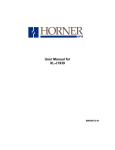
1.3 System configuration
When CBT-205 is used
CPT-20A
CCT-235-2 / , CCT-235- / , D
RS-422A
Host computer
CMT-200
COT-200
CBT-205
(Fig. 1.3-1)
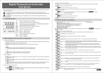
When CBT-210 is used
CPT-20A
CCT-235-2 / , CCT-235- / , D
RS-422A
Host computer
CMT-200
COT-200
CBT-210
(Fig. 1.3-2)
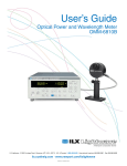
1.4 Parameter exchange
Parameter exchange is shown below.
Host computer
(1) Sets and monitors
the C series.
CPT-20A
(2) Receives data from
the host computer.
(3) Returns a response
data to the host
computer.
(4) Sets and monitors
the CCT-235.
CCT-235
(5) Receives data from
the CPT-20A and
performs the
control.
(6) Returns its
response data
to the CPT-20A.
CPT-20A does not manage the setting ranges of the CCT-235. Therefore, when the host computer
sets the set value of the C series, the value should be within the setting range of the CCT-235.
6
2. Model name
2.1 Model name
(1) Power source host link unit: CPT-20A
(2) Temperature control unit: CCT-235
2-channel specification
CCT-2 3 5- 2
/ ,
Control action 3
Alarm action
Control points
Control output
Input
5
2
R
S
A
E
R
V
A
Option
W(20A)
W(50A)
Series name: CCT-235
PID action (with auto-tuning)
Alarm 1 (A1): High limit, (*1)
Alarm 2 (A2): Low limit
2 channels
Relay contact
Non-contact voltage
DC current
Thermocouple
RTD
DC voltage
DC current
Heater burnout alarm (20A) (*2)
Heater burnout alarm (50A) (*2)
Heating/Cooling specification
CCT-2 3 5/ ,D ,
Control action 3
Series name: CCT-235
PID action (with auto-tuning)
Alarm 1 (A1): High limit,
(*1)
Alarm action
5
Alarm 2 (A2): Low limit
R
Relay contact
Control output
S
Non-contact voltage
A
DC current
E
Thermocouple
R
RTD
Input
V
DC voltage
A
DC current
DR
Relay contact
Cooling output
DS
Non-contact voltage
DA
DC current
W(20A) Heater burnout alarm (20A) (*2)
Option
W(50A) Heater burnout alarm (50A) (*2)
(*1) One alarm from12 types and No alarm can be selected by keypad from a choice of:
High limit alarm, Low limit alarm, High/Low limits alarm, High/Low limit range alarm,
Process high alarm and Process low alarm, and standby functions added to those alarms
and No alarm action
(*2) Heater burnout alarm cannot be applied to DC current output type.
Note:
• The input or output for 2 channels are of the same specification.
Different specifications are not allowed.
• 2-channel specification unit and Heating/Cooling specification unit can be used together.
(3) Base unit: CBT-205, CBT-210
(4) Communication cable: CPM, CPP
7
2.2 How to read model name label
Warning
Turn the power supply to the instrument OFF before confirming the model name label.
Working with the power switched ON may result in severe injury or death due to Electric Shock.
(1) Power source host link unit: CPT-20A
Model name labels are attached to the case and inner assembly. See (Fig. 2.2-1).
[Example]
CPT–20A
Model name: CPT-20A
TC
Option: Terminal cover
No.xxxxxx
Serial number (indicated only on the inner assembly.)
(Fig. 2.2-1)
(2) Temperature control unit: CCT-235
2-channel specification
Model name labels are attached to the case and inner assembly. See (Fig. 2.2-2), (Fig. 2.2-3).
CCT–235-2R/E
Model name: CCT–235-2R/E
W (20A)
Option: Heater burnout alarm (20A)
No.xxxxxx
Serial number (indicated only on the inner assembly.)
(Fig. 2.2-2)
Heating/Cooling specification
CCT–235-2R/E, DR Model name: CCT–235-2R/E, DR
W (20A)
Option: Heater burnout alarm (20A)
No.xxxxxx
Serial number (indicated only on the inner assembly.)
(Fig. 2.2-3)
(3) Base unit: CBT-205, CBT-210
A model name label is attached to the left side of the socket for CPT-20A. See (Fig. 2.2-4).
CBT–210
Model name: CBT–210
No.xxxxxx
Serial number
(Fig. 2.2-4)
8
3. Name and functions of the sections
(1) Power source host link unit: CPT-20A
4
TX/RX
1
POWER
2
5
3
Terminal block for
power source
Terminal block for
digital input/output
Internal assembly
(Fig. 3-1)
Communication indicator
When communicating between a host computer and CPT-20A, a yellow LED lights up.
Instrument power indicator
When the power supply to the instrument is turned ON, a green LED lights up.
Modular jack
Connects the monitor, console or other CPT-20A units.
Rotary switch for instrument number setting
Sets the instrument number of the CPT-20A.
DIP switch for communication setting
Selects communication settings for the CPT-20A.
(2) Temperature control unit:
CCT-235-2 / (2-channel specification), CCT-235- / , D (Heating/Cooling specification)
TX
PW
O1
O2
1
2
3
4
5
6
7
Terminal block
for input/output
Top of the
instrument
Communication indicator
When communicating between the CCT and CPT,
a yellow LED lights up.
Instrument power indicator
While the power supply to the instrument is turned ON,
a green LED lights up.
OUT1 control output (Heating) indicator
When OUT1 control output or Heating output (Heating/
Cooling specification) is ON, a green LED lights up.
(For DC current output type, it flashes corresponding to
the manipulated variable.)
OUT2 control output (Cooling) indicator
When OUT2 control output or Cooling output (Heating/
Cooling specification) is ON, a green LED lights up.
(For DC current output type, it flashes corresponding to
the manipulated variable.)
(Fig. 3-2)
Rotary switch for sensor selection
Selects a sensor type.
Socket to input Ch1 heater burnout alarm (CT)
Connects Ch1 heater burnout alarm (CT) input.
Socket to input Ch2 heater burnout alarm (CT)
Connects Ch2 heater burnout alarm (CT) input. (Unavailable for Heating/Cooling specification)
9
4. Setup
Warning
Turn the power supply to the instrument OFF before performing the setup.
Working with the power switched ON may result in severe injury or death due to Electric Shock.
Note: • Set up the CPT-20A and CCT-235 first before inserting those units into the CBT-200 socket.
• The input or output for 2 channels are of the same specification.
Different specifications are not allowed.
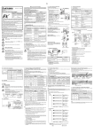
(1) Power source host link unit: CPT-20A
Switch setting
Using a small screwdriver (flat-blade or Philips head) or tweezers, set up the rotary and DIP switch
of the CPT-20A.
See (Fig. 4-1).
TX/RX
1
1
2
3
4
5
6
7
8
POWER
2
DI1
DI2
DI3
7 8 9A
E
6
F0 1 2
34 5
BCD
DO1
DO2
DO3
Terminal block
for power source
Terminal block for
digital input/output
Internal assembly
(Fig. 4-1)
Rotary switch for instrument number setting
Sets the instrument number of the CPT-20A.
Setting range: 0 to 15 (Rotary switch is represented by hexadecimal figures.)
DIP switch for communication setting (Default value: OFF for all settings)
Communication speed and terminator setting
DIP switch No.
ON
OFF
No.1
19200bps
9600bps
No.2
Terminator ON
Terminator OFF
10
O
N
Communication form (DIP switch must be set as follows.)
DIP DIP
DIP
DIP
SW
SW
SW
SW
Communication object or PLC
No.3 No.4 No.5 No.6
CMT-200, COT-200, Programmable
OFF OFF OFF OFF
interface, Personal computer, etc.
Protocol
Register
Command
DM
RD/WR
R
WR/WW
D
WR/WW
Shinko
protocol
ON
OFF
OFF
OFF
SYSMAC (Omron Corp.)
Host link unit
OFF
ON
OFF
OFF
MELSEC
(Mitsubishi Electric Corp.)
ON
ON
OFF
OFF
FX-2N
(Mitsubishi Electric Corp.)
OFF
OFF
ON
OFF
MICREX-F (Fuji Electric CO., LTD.)
ON
OFF
ON
OFF
MELSEC
(Mitsubishi Electric Corp.)
OFF
ON
ON
OFF
MELSEC
(Mitsubishi Electric Corp.)
ON
ON
ON
ON
FA-M3
(Yokogawa Electric Corp.) Host link unit
ON
ON
ON
ON
Modbus protocol compatible products
Host link unit
Format 4
Host link unit
Format 4
Host link unit
Host link unit
Format 4
Host link unit
Format 4
SI, W30
R
QR/QW
D
QR/QW
D
WRD/WWR
Modbus
protocol
Compatible host link units and their manufacturers
PLC manufacturer
Model
AJ71UC24,
AJSJ71UC24-R2/R4/PRF,
A1SJ71C24-R2/R4/PRF, QJ71C24
Mitsubishi Electric Corp.
Omron Corp.
LK201-V1, LK202-V1, CS1W-SCU21-V1, CJ1W-SCU21, CJ1W-SCU41
Fuji Electric CO., LTD.
NC1L-RS2, NC1L-RS4
Yokogawa Electric Corp. F3LC11-1F, F3LC11-1N, F3LC12-1F, F3LC11-2N
Digital output setting (DIP switch)
DIP SW DIP SW
Digital output function
No.7
No.8
OFF
OFF
ON or OFF with communication command (*)
ON
OFF
DO1: Alarm 1 DO2: Alarm 2
DO3: Heater burnout alarm
OFF
ON
DO1: Alarm 1 DO2: Alarm 2
DO3: Loop break alarm
ON
ON
DO1: Alarm 1 DO2: Heater burnout alarm DO3: Loop break alarm
(*) works only when data is sent to the CPT-20A data item [digital output (0041H)] using Shinko or
Modbus protocol. (See pages 43, 77.)
Explanation of digital output setting
[Example 1] DIP switch No.7: OFF, 8:OFF
Any digital output (DO1 to DO3) of CPT-20A can be set.
[Example 2] DIP switch No.7: ON, 8: OFF
If Alarm 1, Alarm 2 or Heater burnout alarm occurs in any one of the channels of CCT-235,
relay contact of DO1, DO2 or DO3 is turned ON.
[Example 3] DIP switch No.7: OFF, 8: ON
If Alarm 1, Alarm 2 or Loop break alarm occurs in any one of the channels of CCT-235,
relay contact of DO1, DO2 or DO3 is turned ON.
[Example 4] DIP switch No.7: ON, 8: ON
If Alarm 1, Heater burnout alarm or Loop break alarm occurs in any one of
the channels of CCT-235, relay contact of DO1, DO2 or DO3 is turned ON.
11
(2) Temperature control unit
(2-channel specification)
CCT-235-2 /
CCT-235- / , D (Heating/Cooling specification)
• Set up the Rotary switch.
Input type setting
Using a small flat-blade screwdriver or tweezers, set up the rotary switch of CCT-235 for input setting.
See (Fig. 4-2).
6
0
4 5
7
3
1
2
Top of the
instrument
(Fig. 4-2).
Rotary
SW No.
0
1
2
3
4
5
6
7
TC input
K
J
R
RTD input
DC voltage input
Pt100
JPt100
V DC (when input is
disconnected: Output
OFF)
mA DC (when input is
disconnected: Output
OFF)
B
PL-
DC current input
V DC (when input is
disconnected: Output
ON)
mA DC (when input is
disconnected: Output
ON)
N
K (With a decimal point)
J (With a decimal point)
For the rated scale range of each input, refer to Section “11. Specifications” (Page 89).
For RTD input, be sure to set the rotary switch number to “0” or “1”.
For DC voltage input, be sure to set the rotary switch number to “2” or “4”.
For DC current input, be sure to set the rotary switch number to “3” or “5”.
12
5. Mounting
5.1 Site selection
This instrument is intended to be used under the following environmental conditions (IEC61010-1):
Overvoltage category , Pollution degree 2
Ensure the mounting location corresponds to the following conditions:
(1) A minimum of dust, and an absence of corrosive gases
(2) No flammable, explosive gases
(3) No mechanical vibrations or shocks
(4) No exposure to direct sunlight, an ambient temperature of 0 to 50 (32 to122 ) that does not
change rapidly
(5) An ambient non-condensing humidity of 35 to 85%RH
(6) No large capacity electromagnetic switches or cables through which large current is flowing
(7) No water, oil or chemicals or where the vapors of these substances can come into direct contact
with the unit
96
5.2 External dimensions (Unit: mm)
(1) Power source host link unit: CPT-20A
48
94
(Fig. 5.2-1)
96
(2) Temperature control unit
CCT-235-2 / (2-channel specification), CCT-235- / , D
24
94
(Fig. 5.2-2)
13
(Heating/Cooling specification)
4
96
(3) Base unit: CBT-210, CBT-205
2
168(For CBT-210: 288)
26
(Fig. 5.2-3)
(4) Communication cable
CPM
(Fig. 5.2-4)
CPP
(
*2
(Fig. 5.2-5)
(*1) Cable length can be extended by a meter each time.
(*2) Cable length can be extended by 500mm each time when cable length is 500mm or longer.
Cable length can be extended by 100mm each time when cable length is 500mm or less.
Pin No.
1
2
3
4
5
6
Wire color
Gray/Red
White/Red
Orange/Red
Orange/Black
White/Black
Gray/Black
14
5.3 Mounting
(1) How to mount the CBT-200 on the DIN rail
CBT-200 (CBT-205, CBT-210)
Caution
• Mount the DIN rail horizontally.
• If the DIN rail is mounted in a position susceptible to vibration or shock, be sure to use commercially
available fastening plates at the end of CBT-200.
Fastening plates
Manufacturer
Omron Corp.
IDEC Corp.
Matsushita Electric Works, Ltd.
Model name
End plate
PFP-M
DIN rail stops
BNL6P, BNL8P
Fastening plate ATA4806
• Do not confuse the top and bottom of the CBT-200.
• When mounting or removing the units (CPT-20A, CCT-235), the units have to be slanted a little.
Therefore do not mount any other instruments within 10cm of space from the CBT-200 base unit.
Fit the upper dented part of the back of CBT-200 to one side of the DIN rail. See (Fig. 5.3-1).
Fit the lower dented part of the back of CBT-200 to the other side of the DIN rail.
The CBT-200 will be fixed to the DIN rail with a clicking sound. See (Fig. 5.3-1).
CBT-200
1.5mm
1
Auxiliary board
of the CBT-200
DIN rail
2
Lock
(Fig. 5.3-1)
15
n CBT-205
Three places to lock the CBT-205 and two places to mount the mounting bracket are shown below.
DIN rail
Mounting
bracket
Mounting
bracket
Lock
Lock
(Fig. 5.3-2)
Lock
n CBT-210
Four places to lock the CBT-210 and two places to mount the mounting bracket are shown below.
DIN rail
Mounting
bracket
Mounting
bracket
Lock
Lock
Lock
Lock
(Fig. 5.3-3)
(2) How to remove the CBT-200 from the DIN rail
By using a flat-blade screwdriver, pull down the lock of the lower part of the CBT-200
See (Fig. 5.3-4).
Keeping the lock down, pull the CBT-200 up. See (Fig. 5.3-4).
CBT-200
Control panel
DIN rail
2
1
(Fig. 5.3-4)
Lock
16
(3) How to mount the CPT-20A and CCT-235 to the CBT-200
Caution
Do not confuse the top and bottom of each unit (CPT-20A, CCT-235).
If force is applied to the unit in the wrong direction, the PCB may be damaged.
Hook the upper part of the CPT-20A unit to the upper part of the CBT-200 base unit to be mounted.
See (Fig. 5.3-5).
Using the mounted part as the support, fit the lower part of the CPT-20A unit to the base unit.
The CPT-20A will be completely fixed to the CBT-200 base unit with a clicking sound. See (Fig. 5.3-5).
1
CBT-200
CPT-20A
(Fig. 5.3-5)
2
6. Wiring
Warning
Turn the power supply to the instrument OFF before wiring.
Working with the power switched ON may result in severe injury or death due to Electric Shock.
Moreover, the instrument must be grounded before the power supply to the instrument is turned
on.
Caution
• Do not leave bits of wire in the instrument (CPT-20A, CCT-235), because they could cause fire or
malfunction.
• Insert the connecting cable into the designated connector securely to prevent malfunction.
• Connect the wire for AC power source with its designated terminal as described in this instruction
manual. The CPT-20A will be damaged if the AC power source wire is connected to a different terminal.
• For the ground terminal of the CPT-20A, use 2mm2 or more of thick wire.
However, avoid grounding in conjunction with the power line.
• Use the solderless terminal with an insulation sleeve in which the M3 screw fits when wiring the
CPT-20A terminals.
• The terminal block of the CPT-20A is designed to be wired from the left side. The lead wire must be
inserted from the left side of the terminal, and fastened with the terminal screw.
• Tighten the terminal screw with the specified torque.
If excessive force is applied to the screw when tightening, the screw or case may be damaged.
• Do not apply a commercial power source to the sensor connected to the CCT-235 input terminal
nor allow the power source to come into contact with the sensor, as the input circuit may be burnt out.
• Use a thermocouple, compensating lead wire and the 3-wire RTD corresponding to the input
specification of the CCT-235.
• When using a relay contact output type CCT-235, externally use a relay according to the capacity
of the load to protect the built-in relay contact.
• When wiring, keep input wires (thermocouple, RTD, etc.) away from AC sources or load wires.
• To prevent the unit from harmful effects of unexpected level noise, it is recommended that
a surge absorber be installed between the electromagnetic switch coils.
• Externally install a protecting circuit in case there is unexpected trouble due to the environment,
aging, etc.
• The C series has neither a built-in power switch nor a fuse. Therefore, it is necessary to install them
in the circuit near the external controller.
(Recommended fuse: Time-lag fuse, rated voltage 250V AC, rated current 3.15A)
17
6.1 Terminal arrangement
(1) Power source host link unit: CPT-20A
TX/RX
SG
RXB
TXB
TXA
RXA
SG
1
POWER
5
DI1
6
6
Digital
input
DI2
7
DI3
8
9
DO1
10
100 to 240V AC
50/60Hz
Ground
(2) Temperature control unit
CCT-235-2 / (2-channel specification)
+
Ch2 output
3
2
4
5
3
13
4
14
DO2
Digital
output
DO3
Terminal block for
digital input/output
(Heating/Cooling specification)
O2
Ch1 CT input
(option)
Ch2 CT input
(option)
Thermocouple
+ A
B
6
Ch1 input
B
7
8
12
Relay contact (R/ )
Non-contact
TX
voltage (S/ )
PW
O1
DC current (A/ )
TX
PW
O1
O2
1
2
CCT-235- / , D
Relay contact (R/ )
+
Ch1 output
11
Terminal block
for power source
(Fig. 6.1-1)
Non-contact
voltage (S/ )
DC current (A/ )
1
+
9
B
B
1
+
Cooling output
3
Non-contact
voltage (DS)
DC current (DA)
5
Thermocouple
+
A
6
B
CT input
(option)
2
4
Relay contact (DR)
A
10
+
Heating output
Ch2 input
7
B
8
RTD
9
10
RTD
Terminal block
for input/output
Terminal block
for input/output
Top of the
instrument
Top of the
instrument
(Fig. 6.1-2)
6.2 Solderless terminal
Use a solderless terminal with an insulation sleeve in which the M3 screw fits as shown below.
3.2mm
5.8mm or less
5.8mm or less
3.2mm
(Fig. 6.2-1)
Solderless
terminal
Y type
Round type
Manufacturer
Model name
Nichifu Terminal Industries CO.,LTD.
1.25Y-3
Japan Solderless Terminal MFG CO., LTD.
Nichifu Terminal Industries CO.,LTD.
VD1.25-B3A
1.25-3
Japan Solderless Terminal MFG CO., LTD.
V1.25-3
18
Tightening torque
0.6N・m
Max. 1.0N・m
6.3 Wiring example
• CCT-235-2R/E
3-phase
TX
PW
O1
O2
Surge
absorber
1
2
3
4
5
6
7
8
9
Surge
absorber
Electromagnetic
switch
Ch1 TC
Ch2 TC
Electric
furnace 2
Electric
furnace 1
10
(Fig. 6.3-1)
• CCT-235-2S/E
3-phase
TX
PW
O1
O2
SSR
SSR
Ch1 TC
Ch2 TC
Electric
furnace 1
Electric
furnace 2
(Fig. 6.3-2)
19
1
2
3
4
5
6
7
8
9
10
• CCT-235-R/E, DR
TX
PW
O1
O2
Surge absorber
Single phase
1
2
3
4
5
6
7
8
9
10
Electromagnetic
switch
+
Cooling fan
Electric furnace
Thermocouple
Heater
Electromagnetic switch
Surge absorber
(Fig. 6.3-3)
• CCT-235-S/E, DS
Single phase
TX
PW
O1
O2
+
SSR
+
Cooling fan
Electric furnace
Thermocouple
Heater
SSR
+
(Fig. 6.3-4)
20
1
2
3
4
5
6
7
8
9
10
7. Connection with a personal computer and PLC
7.1 Connection with a personal computer
7.1.1 Application example
1 block of C series
1 block
TX/RX
POWER
RS-232C
TX
PW
01
02
TX
PW
01
02
TX
PW
01
02
TX
PW
01
02
TX
PW
01
02
RS-422A
Communication converter
CCT-235 (Maximum 10 units)
CPT-20A
Host computer
(Fig. 7.1.1-1)
Multiple blocks of C series
1 block
TX/RX
POWER
TX
PW
01
02
TX
PW
01
02
TX
PW
01
02
TX
PW
01
02
TX
PW
01
02
TX
PW
01
02
TX
PW
01
02
TX
PW
01
02
TX
PW
01
02
TX
PW
01
02
TX
PW
01
02
TX
PW
01
02
TX
PW
01
02
RS-422A
RS-232C
Communication converter
TX/RX
POWER
Host computer
RS-422A
TX/RX
POWER
TX
PW
01
02
Maximum 16 blocks
CPT-20A
CCT-235 (Maximum 10 units)
(Fig. 7.1.1-2)
21
TX
PW
01
02
7.1.2 Setup
When the communication speed is 9600bps between a host computer and CPT-20A, and
1 block of C series is connected
• Set the instrument number of CPT-20A to “0”. (See page 10.)
• Set the DIP switch for communication of CPT-20A. (See pages 10 and 11.)
Switch No.1
: OFF (Communication speed: 9600bps)
Switch No.2
: ON (Terminator: ON)
Switch No.3 to 6 : OFF (Communication form: SHINKO protocol)
Switch No.7 and 8 : OFF (Digital output: OFF)
• Set the communication speed of the host computer to 9600bps.
As to the communication speed setting, refer to the Instruction manual for the host computer.
When communication speed is 19200bps between a host computer and CPT-20A, and
10 blocks of C series are connected
• Set the instrument number of CPT-20A connected with the host computer first to “0”.
Then, give a number in order (1 to 9) to other CPT-20A units to be connected.
See page 10.
• Set the DIP switch for communication of CPT-20A. See pages 10 and 11.
Switch No.1
: ON (Communication speed: 19200bps)
[Turn the switch No.1 of 10 units to ON.]
Switch No.2
: OFF (Terminator: OFF)
[Turn the switch No.2 of the last unit to ON.]
Switch No.3 to 6 : OFF (Communication form: SHINKO protocol)
[Turn the switches No.3 to 6 of 10 units to OFF.]
Switch No.7 and 8 : OFF (Digital output: OFF)
[Turn the switches No.7 and 8 of 10 units to OFF.]
• Set the communication speed of the host computer to 19200bps.
As to the communication speed setting, refer to the Instruction manual for the host computer.
7.1.3 Wiring
Terminal arrangement of a personal computer connector
[D sub 9-pin connector]
Pin No.
Code
1
DCD
2
RXD
3
TXD
4
DTR
5
GND
6
DSR
7
RTS
8
CTS
9
RI
[D sub 25-pin connector]
Pin No.
Code
1
FG
2
TXD
3
RXD
4
RTS
5
CTS
6
DSR
7
GND
8
DCD
20
DTR
22
RI
22
Wiring example
• D sub 9-pin connector
Pin 2
Pin 3
Pin 5
4
1
7
(RXD)
(TXD)
(GND)
6 Connected
8
TX
RX
GND
TXA
TXB
Connected
Terminator
Modular
jack
1 6
5
2
4
3
RXA
RXB
CPM
Communication
converter
Host computer
CPT-20A
(Fig.7.1.3-1)
• D sub 25-pin connector
Pin 2 (TXD)
Pin 3 (RXD)
Pin 7 (GND)
4
5
6
8
RX
TX
GND
TXA
TXB
Connected
20
Connected
Terminator
Host computer
Modular
jack
1 6
5
2
4
3
RXA
RXB
CPM
Communication
converter
CPT-20A
(Fig.7.1.3-2)
• For the wiring of the communication converter, refer to the instruction manual for each converter.
• Use 120 , 1/2W or more of terminator.
7.2 Connection with a Mitsubishi PLC
7.2.1 Application example
Mitsubishi Calculator link unit (AJ71UC24, A1SJ71UC24-R4)
Micro PLC (FX2N-XXMR)
Serial communication unit (QJ71C24, QJ71C24-R2)
1 block
TX/RX
Protocol:
Mitsubishi protocol
POWER
TX
PW
01
02
TX
PW
01
02
TX
PW
01
02
TX
PW
01
02
RS-422A
Calculator link unit (AJ71UC24,
A1SJ71UC24-R4),
Micro PLC (FX2N-XXMR) or
Serial communication unit
(QJ71C24, QJ71C24-R2)
CPT-20A
(Fig. 7.2.1-1)
23
CCT-235 (Maximum 10 units)
T
P
X
0
W
0
1
2
7.2.2 Setup
Setup of Mitsubishi Calculator link unit (AJ71UC24)
1
MODE
STATION NO.
x10
2
STATION NO.
x1
3
SW11
SW12
SW13
SW14
SW15
SW16
SW17
SW18
SW21
SW22
SW23
SW24
ON
Sets the transmission control procedure (protocol)
and control procedure of RS-422 or RS-232C.
Set to 8 (Format 4).
Sets the instrument number of the double digit (x10).
Set the number to 0.
Sets the instrument number of the single digit (x1).
Set the number to 0.
Sets the transmission specifications.
See (Table 7.2.2-1).
Set the items except baud rate to
.
4
ON
(Fig. 7.2.2-1)
(Table 7.2.2-1)
Setting switch
SW11
SW12
SW13
SW14
SW15
SW16
SW17
SW18
SW21
SW22
SW23
SW24
Setting item
Main channel setting
Data bit setting
Baud rate
Communication speed setting
Parity setting
Even/Odd parity setting
Stop bit setting
Checksum setting
Writing during RUN
Calculator link/multi-drop link
selection
Not used
24
Setting switch ON
RS-422
8 bits
9600bps
ON
OFF
ON
Yes
Even
2 bits
Yes
Possible
Setting switch OFF
RS-232C
7 bits
19200bps
OFF
ON
ON
No
Odd
1 bit
No
Impossible
Calculator link
Multi-drop link
Setup of Mitsubishi Calculator link unit (A1SJ71UC24-R4)
SW01
ON
SW02
STATION NO.
SW03
SW04
x10
1
x1
2
ON
SW05
4
SW06
SW07
SW08
SW09
SW10
MODE
SW11
Sets the instrument number of the double digit (x10).
Set the number to 0.
Sets the instrument number of the single digit (x1).
Set the number to 0.
Sets the transmission control procedure
(protocol) and control procedure of
RS-422 or RS-232C.
Set to 8 (Format 4).
Sets the transmission specifications.
See (Table 7.2.2-2).
Set the items except for the baud rate to
.
3
SW12
(Fig. 7.2.2-2)
(Table 7.2.2-2)
Setting switch
SW01
SW02
SW03
SW04
SW05
SW06
SW07
SW08
SW09
SW10
SW11
SW12
Setting item
Not used
Calculator link/multi-drop link
selection
Not used
Writing during run setting
Baud rate
Communication speed setting
Data bit setting
Parity setting
Even/Odd parity setting
Stop bit setting
Checksum setting
25
Setting switch ON
Setting switch OFF
Calculator link
Multi-drop link
Possible
9600bps
ON
OFF
ON
8 bits
Yes
Even
2 bits
Yes
Impossible
19200bps
OFF
ON
ON
7 bits
No
Odd
1 bit
No
Setup of Mitsubishi Micro PLC (FX2N-XXMR)
Set up the station number (0) and communication of no procedure or communication of the
calculator link (communication format D8120) which uses designated protocol in the program.
Specification of communication format D8120 (Set the items to
except the baud rate.)
(Table 7.2.2-3)
Contents
Bit No.
Name
0 (Bit OFF)
1 (Bit ON)
b0
Data length
7 bits
8 bits
b1
b2, b1
Parity
b2
( 1, 1): Even
b3
Stop bit
1 bit
2 bits
b4
b7, b6, b5, b4
b5
Baud rate
( 1, 0, 0, 0): 9600bps
Must be specified
b6
(bps)
( 1, 0, 0, 1): 19200bps
b7
b8
Header
No
Yes
b9
Terminator
No
Yes
b10
b11, b10
Control cable
b11
( 0, 0): RS-485 interface
b12
Not available
b13
Checksum
Not applied
Applied
b14
Protocol
Not used
Used
b15
Control procedure
Format 1
Format 4
Note
Communication format is used to decide the setting of the above (Table7.2.2-3) and
can be set by programming to the special data memory (D8120) of the PLC.
When the setting is changed, be sure to turn the power supply to the PLC OFF and then ON again,
otherwise the changed data will not be effective.
Communication format setting
When setting the contents of (Table 7.2.2-3), set the program to the special data memory (D8120)
of the PLC as follows. See page 30.
When the baud rate is 9600bps
b15
b0
D8120 = [1110
0000
1000
0110 ]
E
0
8
6
M8002
MOV HE086 D8120
(Fig. 7.2.2-3)
When the baud rate is 19200bps
b15
D8120 = [1110
0000
1001
E
0
9
b0
0110 ]
6
M8002
MOV HE096 D8120
(Fig. 7.2.2-4)
Station number setting
Be sure to set the station number to “0”.
Set the program to the special data memory (D8121) of the PLC as follows.
M8002
MOV H0000 D8121
(Fig. 7.2.2-5)
26
Setup of Serial communication unit (QJ71C24, QJ71C24-R2)
Install the GX Developer to a host computer, perform settings such as communication speed,
transmission specification and communication protocol, then set up the unit with PC writing function.
• Setting from the GX Developer:
(1) I/O allocation setting
Set the following items.
Type: “Intelligent”, Model name: QJ71C24, QJ71C24-R2, Number of points: 32
(2) Switch setting for I/O unit, Intelligent function unit
Set the following items.
• Transmission setting (Action setting: Independent, Data bit: 7, Parity bit: Yes (Even),
Stop bit: 1, Checksum code: Yes, Writing during RUN: Allowed,
Setting change: Allowed)
• Communication speed setting (9600bps or 19200bps)
• Communication protocol setting (Format 4)
For the setting method, refer to the User’s manual for Serial communication unit (Basic).
7.2.3 Wiring
Connection between Mitsubishi Calculator link unit (AJ71UC24, A1SJ71UC24-R4) and CPT-20A
TX/RX
Communication cable
CPM
POWER
5
RS-422A
DI1
6
DI2
DI3
7
Calculator link unit
SDA
SDB
RDA
RDB
SG
FG
2
5
3
4
1
6
8
1
9
6
10
100 to 240V AC
50/60Hz
Ground
1
11
2
12
3
13
4
14
DO1
DO2
DO3
(Fig. 7.2.3-1)
• For the communication line RS-422A, install a terminal resistor, referring to the Instruction
manual for each PLC.
27
Connection between Mitsubishi Micro PLC (FX2N-XXMR) and CPT-20A
Communication cable CPM
TX/RX
POWER
RS-422A
5
DI1
6
MITSUBISHI
1
8
6
10
9
MELSEC FX2N-XXMR
100 to 240V AC
50/60Hz
Ground
O/R
O/B
W/R
W/B
G/R
RDARDBSDASDB SG
3
4
2
5
1
6
DI2
DI3
7
1
11
2
12
3
13
4
14
DO1
DO2
DO3
O: Orange
R: Red
B: Black
W: White
G: Gray
G/B
(Fig. 7.2.3-2)
Connection between Serial communication unit (QJ71C24, QJ71C24-R2) and CPT-20A
TX/RX
Communication cable
CPM
POWER
5
Serial
communication
unit
SDA
SDB
RDA
RDB
SG
FG
DI1
6
RS-422A
DI2
DI3
7
①
8
⑥
10
9
②
⑤
③
1
11
④
2
12
3
13
4
14
①
100 to 240V AC
50/60Hz
⑥
Ground
(Fig.7.2.3-3)
28
DO1
DO2
DO3
7.2.4 Initial setting
(1) Initial setting of Mitsubishi Calculator Link Unit (AJ71UC24, A1SJ71UC24-R4)
To communicate with the C series, set the address from the PLC in order to store the data of
each set value of the C series when the power supply to the PLC is turned on.
Communication is impossible unless the address for storing the data of each set value of the
C series is set.
Be sure to set the program to execute the sample program as follows.
Note
Do not use register addresses (R0000 to R0002) of the PLC when setting the program
since the addresses (R0000 to R0002) are used for the top address and Communication
parameter setting completion flag 1 and 2.
Sample program (Initial setting and SV, PID setting change)
M9038
M10
MOV
K1000 R0000
(1)
MOV
K10
R1001
(2)
MOV
HFFFF R1005
(3)
MOV
HFFFF R1006
(4)
MOV
H007F R1007
(5)
MOV
H1234 R0001
(6)
MOV
H5678 R0002
(7)
M11
MOVP K2
SV setting PID setting
change relay change relay
M11
M10
T0
(8)
K30
T0
SV setting completion wait timer (3s)
MOVP K4
PID setting SV setting
change relay change relay
R1008
R1008
(9)
K30
T1
PID setting completion wait timer (3s)
RST
M10
(10)
RST
(11)
SV setting completion wait timer (3s)
T1
M11
PID setting completion wait timer (3s)
(Fig. 7.2.4-1)
END
Explanation of the sample program
M9038 is a special relay that turns only one scan ON after RUN.
MOVP is a transmission command for executing 1 scan transmission.
(1) To the address R0000, set the top address of the register area which is used for the
communication with the CPT-20A.
The top address is set to R1000 with the sample program.
(2) To the address R1001, set the number of CCT-235 units connected.
10 units of the CCT-235 connected are set with the sample program.
(3) To the address R1005, set Communication item Used/Not used selection flag.
See p.55 for the Communication item
(4) To the address R1006, set Communication item Used/Not used selection flag.
See p.55 for the Communication item.
(5) To the address R1007, set Communication item Used/Not used selection flag.
See p.55 for the Communication item.
(6) To the address R0001, set Communication parameter setting completion flag 1
[Fixed value 4660 (1234H)].
(7) To the address R0002, set Communication parameter setting completion flag 2
[Fixed value 22136 (5678H)].
(8) After SV setting has been changed, set Set value change flag 2 (main set value change)
to the address R1008. See p.56.
29
(9) After PID setting has been changed, set the Set value change flag 4 (PID parameter change)
to the address R1008. See p.64.
(10) After SV setting change completion wait timer (3sec.) has expired, reset the SV setting change relay.
(11) After PID setting change completion wait timer (3sec.) has expired, reset the PID setting change relay.
(2) Initial setting of Mitsubishi Micro PLC (FX2N-XXMR)
To communicate with the C series, set the address from the PLC for storing the data of each set value
of the C series when the power supply to the PLC is turned on.
Communication is impossible unless the address for storing the data of each set value of the C series
is set.
Be sure to set the program to execute the sample program as follows.
Note
Do not use register addresses (D0000 to D0002) of the PLC when setting the program
since the addresses (D0000 to D0002) are used for the top address and Communication
parameter setting completion flag 1 and 2.
Sample program (See p.29 for the setting change)
M8002
MOV K1000 D0000
(1)
MOV K10
D1001
(2)
MOV HFFFF D1005
(3)
MOV HFFFF D1006
(4)
MOV H007F D1007
(5)
MOV H1234 D0001
(6)
MOV H5678 D0002
(7)
MOV HE086 D8120
(8)
MOV H0000 D8121
(9)
END
(Fig. 7.2.4-2)
Explanation of the sample program
M8002 is a special relay that turns only one scan ON after RUN.
(1) To the D0000 address, set the top address of the register area which is used for the
communication with the CPT-20A.
The top address is set to R1000 with the sample program.
(2) To the address D1001, set the number of CCT-235 connected.
10 units of the CCT-235 connected are set with the sample program.
(3) To the address D1005, set Communication item Used/Not used selection flag.
See page 59 for the communication item.
(4) To the address D1006, set Communication item Used/Not used selection flag.
See page 59 for the communication item.
(5) To the address D1007, set Communication item Used/Not used selection flag.
See page 60 for the communication item.
(6) To the address D0001, set Communication parameter setting completion flag 1
[Fixed value 4660 (1234H)].
(7) To the address D0002, set Communication parameter setting completion flag 2
[Fixed value 22136 (5678H)].
(8) To the address D8120, set the communication format. See page 26.
(9) To the address D8121, set the station number. See page 26.
• For more information, refer to the User's manual (FX communication RS232C, RS485)
for Mitsubishi Micro PLC (MELSEC-F).
30
(3) Initial setting of Serial communication unit (QJ71C24)
To communicate with the C series, set the address from the PLC for storing data of each set value
of the C series when the power supply to the PLC is turned on.
Communication is impossible unless the address for storing the data of each set value of the
C series is set.
Be sure to set the program to execute the sample program as follows.
Note
Do not use register addresses (D0000 to D0002) of the PLC when setting the program
since the addresses (D0000 to D0002) are used for the top address and Communication
parameter setting completion flag 1 and 2.
Sample program (When D register is used)
See page 30 for the setting change.
SM403
MOV K1000
D0000
(1)
MOV K10
D1001
(2)
MOV HFFFF D1005
(3)
MOV HFFFF D1006
(4)
MOV H007F D1007
(5)
MOV H1234 D0001
(6)
MOV H5678 D0002
(7)
END
(Fig. 7.2.4-3)
Explanation of the sample program
SM403 is a special relay that turns only one scan ON after RUN.
(1) To the D0000 address, set the top address of the register area which is used for the
communication with the CPT-20A.
The top address is set to R1000 with the sample program.
(2) To the address D1001, set the number of CCT-235 connected.
10 units of the CCT-235 connected are set with the sample program.
(3) To the address D1005, set Communication item Used/Not used selection flag.
See page 59 for the Communication item.
(4) To the address D1006, set Communication item Used/Not used selection flag.
See page 59 for the Communication item.
(5) To the address D1007, set Communication item Used/Not used selection flag.
See page 60 for the Communication item.
(6) To the address D0001, set Communication parameter setting completion flag 1
[Fixed value 4660 (1234H)].
(7) To the address D0002, set Communication parameter setting completion flag 2
[Fixed value 22136 (5678H)].
31
7.3 Connection with an Omron PLC
7.3.1 Application example
Omron Host link unit (C200H-LK202-V1)
Omron Serial communication unit (CS1W-SCU21-V1, CJ1W-SCU21, CJ1W-SCU41)
1 block
TX/RX
TX
PW
01
02
POWER
Protocol:
OMRON protocol
TX
PW
01
02
TX
PW
01
02
TX
PW
01
02
TX
PW
01
02
RS-422A
Host link unit
(C200H-LK202-V1)
CPT-20A
CCT-235 (maximum 10 units)
(Fig. 7.3.1-1)
7.3.2 Setup
Setup of Omron Host link unit (C200H-LK202-V1)
LK202-V1
RUN
RCV
(1)
CH
XMT
ERROR
(2)
SW1
SW2
SW3
SW4
(5)
(6)
ON
(4)
(3)
OFF
The front
of the unit
The inside
of the unit
(Fig. 7.3.2-1)
(1) Sets the instrument number of the double digit (x10). Set the number to 0.
(2) Sets the instrument number of the single digit (x1). Set the number to 0.
(3) Sets the communication speed.
Set the communication speed to switch No.5 (9600bps) or No.6 (19200bps).
(4) Sets the command level, parity and transmission code.
Select the switch No.2 to set them.
(5) Sets the terminator Connected or Not connected.
Set the terminator to Connected (ON).
(6) Sets the procedure of 1:1 or 1:N.
Set to 1:N procedure (OFF).
Setup of Serial communication unit (CS1W-SCU21-V1, CJ1W-SCU21, CJ1W-SCU41)
(1) Turn “TERM” (terminator ON/OFF switch) ON, and set “WIRE” (2-wire/4-wire switch) to “4”.
This setting is for the “CJ1W-SCU41”.
For the CS1W-SCU21-V1, CJ1W-SCU21, go to step (2).
32
(2) Connect a personal computer, and start CX-Programmer.
(3) Create I/O table of the PC while off-line (Fig. 7.3.2-2).
Select [CS/CJ/CPU SIO unit] – [Serial Communication Unit] – [Unit number].
(4) Set allocation DM area of the serial communication unit.
Set allocation DM area by programming on-line connection and action mode (Fig. 7.3.2-3).
(e.g.) When installing the serial communication unit next to the CPU unit, and when UNIT No. is set to “0”:
Set D30000 to 8500H (random setting, host link communication, Data length: 7, Stop bit: 2,
Parity: Yes/Even), and set D30001 to 0000H (9600bps) or to 0007H (19200bps).
(Fig.7.3.2-2)
(Fig.7.3.2-3)
(5) Transmit the following to CPU unit.
Transmit the program, PC system setting and I/O table by clicking “Transmit [PC
PC]” on the menu bar.
Refer to User’s manual (Man. No. SBCD-300G) for Serial communication unit for details.
7.3.3 Wiring
Connection between Omron Host link unit (C200H-LK202-V1) and CPT-20A
Connection between Omron Serial communication unit (CS1W-SCU21-V1, CJ1W-SCU21, CJ1W-SCU41)
and CPT-20A
LK202-V1
RUN
RCV
CH
XMT
ERROR
SW1
SW2
SW3
SW4
TX/RX
Communication cable
CPM
POWER
5
RS-422A
DI1
6
DI2
DI3
7
1
8
6
10
9
1
2
3
4
5
100 to 240Vac
50/60Hz
6
7
8
9
Ground
1
11
2
12
3
13
4
14
DO1
DO2
DO3
Connection between Omron Serial communication
unit (CJ1W-SCU41) and CPT-20A
1
2
3
4
5
6
7
8
9
9
5
6
1
3
SDA
SDB
RDA
RDB
SG
D sub 9-pin connector (Male)
on the soldering side
5 W/B
2 W/R
4 O/B
3 O/R
1 G/R
6 G/B
W: White
B: Black
R: Red
O: Orange
G: Gray
B: Black
1
2
3
4
5
6
7
8
9
1 SDA
2 SDB
6 RDA
8 RDB
Shell SG
D sub 9-pin connector (Male)
on the soldering side
33
5 W/B
2 W/R
4 O/B
3 O/R
1 G/R
6 G/B
W: White
B: Black
R: Red
O: Orange
G: Gray
B: Black
(Fig. 7.3.3-1)
7.3.4 Initial setting
Initial setting of Omron Host link unit (C200H-LK202-V1) and Serial communication unit
(CS1W-SCU21-V1, CJ1W-SCU21, CJ1W-SCU41)
To communicate with the C series, set the address from the PLC for storing the data of each
set value of the C series when the power supply to the PLC is turned on.
Communication is impossible unless the address for storing the data of each set value of the
C series is set.
Be sure to set the program to execute the sample program as follows. (Execute only the first scan
of the following program.)
Note
Do not use register addresses (DM0000 to DM0002) of the PLC when setting the program
since the addresses (DM0000 to DM0002) are used for the top address and Communication
parameter setting completion flag 1 and 2.
Sample program
See page 29 for the setting change example.
25315
MOV
#03E8
DM0000
(1)
MOV
#000A
DM1001
(2)
MOV
#FFFF
DM1005
(3)
MOV
#FFFF
DM1006
(4)
MOV
#007F
DM1007
(5)
MOV
#1234
DM0001
(6)
MOV
#5678
DM0002
(7)
(Fig. 7.3.4-1)
END
Explanation of the sample program
25315 is a special auxiliary relay that turns only one scan ON after RUN.
(1) To the address DM0000, set the top address in the memory area which is used for the
communication with the CPT-20A.
DM1000 is set as a top address during the sample program.
(2) To the address DM1001, set the number of CCT-235 connected.
Ten units (the number of the CCT-235 connected) are set with the sample program.
(3) To the address DM1005, set Communication item Used/Not used selection flag.
See page 64 for the communication item.
(4) To the address DM1006, set Communication item Used/Not used selection flag.
See page 64 for the communication item.
(5) To the address DM1007, set Communication item Used/Not used selection flag.
See page 64 for the communication item.
(6) To the address DM0001, set Communication parameter setting completion flag 1
[Fixed value 4660 (1234H)].
(7) To the address DM0002, set Communication parameter setting completion flag 2
[Fixed value 22136 (5678H)].
34
7.4 Connection with a Fuji PLC
7.4.1 Application example
Fuji Interface module (NC1L-RS4)
1 block
TX/RX
Protocol: Fuji
standard transmission
format
TX
PW
01
02
POWER
TX
PW
01
02
TX
PW
01
02
TX
PW
01
02
RS-422A
Interface module
(NC1L-RS4)
CPT-20A
(Fig. 7.4.1-1)
CCT-235 (maximum 10 units)
7.4.2 Setup
Setup of Fuji Interface module (NC1L-RS4)
RS4
8
7
6
5
4
3
2
1
RUN
SND
RCV
DVE
(1)
×10
ADDRESS
×1
(2)
SDA
SDB
(5)
(3)
ON
ON
RDA
RDB
SG
OFF
(4)
6
F0 1 2
3 4 5
7 8 9A
E
FG
BCD
The front
of the unit
The inside
of the unit
(Fig. 7.4.2-1)
(1) Sets the instrument number of the double digit (x10).
Set the number to 0.
(2) Sets the instrument number of the single digit (x1).
Set the number to 0.
(3) Sets the communication speed.
Refer to the (Table 7.4.2-1). (p.37)
Set the baud rate to either 9600bps or 19200bps (Example above: 9600bps).
Set to
except for the baud rate.
(4) Sets the transmission mode.
Select the switch No.3 to set.
(5) Sets the terminator Connected (ON) or Not connected (OFF).
Set the terminator to Connected (ON).
35
TX
PW
01
02
(Table 7.4.2-1)
Baud
rate
SW No.
1
2
3
SW No.
300bps
600bps
1200bps 2400bps 4800bps 9600bps 19200bps
Not used
OFF
OFF
OFF
ON
OFF
OFF
OFF
ON
OFF
ON
ON
ON
Setting item
ON
ON
OFF
OFF
OFF
ON
ON
OFF
ON
Setting switch ON
OFF
ON
ON
Setting switch OFF
4
Stop bit
1 bit
2 bits
5
6
Data length
Even/Odd parity
7 bits
Even
8 bits
Odd
7
8
Parity
Initial setting
Yes
SW setting valid
No
Initial file
7.4.3 Wiring
Connection between Fuji Interface module (NC1L-RS4) and CPT-20A
RS4
TX/RX
Communication cable
CPM
RUN
SND
RCV
DVE
POWER
5
RS-422A
DI1
6
DI2
DI3
7
x 10
8
1
ADDRESS
x1
9
SDA
SDB
RDA
RDB
SG
FG
2
5
3
4
1
6
10
6
100 to 240Vac
50/60Hz
Ground
1
11
2
12
3
13
4
14
DO1
DO2
DO3
(Fig. 7.4.3-1)
7.4.4 Initial setting
Initial setting of Fuji Interface module (NC1L-RS4)
(1) Define the user file area during system definition (File number: W30, File range: the number of
data necessary for the communication, Data format: SI).
For more details, refer to the User’s manual [Command] for Fuji Program controller (MICREX-F).
(2) When communicating with the C series, set the program for the PLC to execute the first scan of
the initial setting (every C series data storage address) when the power supply to the PLC is turned
on.
Communication is impossible unless the initial setting (every C series data storage address) is
performed.
Note
Do not use register addresses (W30.0000 to W30.0002) of the PLC when setting the
program since the addresses (W30.0000 to W30.0002) are used for the top address and
Communication parameter setting completion flag 1 and 2.
36
7.5 Connection with a Yokogawa PLC
For setup and wiring, refer to the Instruction Manual for Personal computer Link Module.
7.5.1 Setup
Setup of Yokogawa Personal computer link module (F3LC11-2N)
(1) Sets the station number setting switch (double digits). Set it to “0”.
(2) Sets the station number setting switch (single digit). Set it to “1”.
(3) Sets the terminator switch. Select “4-WIRE”.
(4) Sets the transmission speed setting switch. For baud rate, set it to 9600bps or 19200bps.
(5) Sets the data setting switch. Refer to (Table 7.5.1-1).
Set to
.
(Table 7.5.1-1)
Number
Function
Setting switch OFF
Setting switch ON
1
Data length
7 bits
8 bits
2
Parity bit
No
Yes
3
Odd/Even parity
Odd
Even
4
Stop bit
1 bit
2 bits
5
Checksum
No
Yes
6
End of text (CR)
No
Yes
7
Protection function
No
Yes
8
OFF
7.5.2 Wiring
Between Personal computer link module (F3LC11-2N) and CPT-20A
TX/RX
Communication cable
CPM
POWER
5
RS-422A
DI1
6
DI2
DI3
7
F3LC11-2N
①
8
⑥
10
9
SD A
⑤
SD B
②
RD A
④
RD B
③
SG
①
SHIELD
⑥
100 to 240V AC
50/60Hz
1
11
2
12
3
13
4
14
DO1
DO2
DO3
Ground
(Fig. 7.5.2)
7.5.3 Initial setting
Initial setting of Personal computer link module (F3LC11-2N)
When communicating with the C series, be sure to set the program on the PLC side so that initial
setting (address for storing C series data) of only one scan can be performed.
It is impossible to communicate if initial setting is not conducted.
37
8. Communication procedure
8.1 Communication procedure
Between a host computer and the CPT-20A
Communications between a host computer and the CPT-20A are started by sending the command
from the host computer, and terminated by receiving the response from the CPT-20A.
Host computer
Command
Data
CPT-20A
• Response with data
When the host computer sends the reading command,
the CPT-20A returns the corresponding set value or
current status as a response.
Command
Acknowledgement
Command
Negative acknowledgement
• Acknowledgement
If the host computer sends the setting command,
the CPT-20A returns an acknowledgement as a
response after the processing is terminated.
• Negative Acknowledgement
When the host computer sends a non-existent command
or when the status is unable to be set (warm-up status
of the CPT-20A when the power is turned on), the CPT-20A
returns a negative acknowledgement as a response.
Command
No response
• No response
The CPT-20A will not respond when there is a framing error
or checksum error (for Shinko protocol), or when LRC
discrepancy (Modbus protocol ASCII mode) is detected.
Communication timing
CPT-20A side
When the CPT-20A starts transmission through the RS-422A communication line, the CPT-20A
is arranged so as to provide an idle status (mark status) transmission period of one or more
characters before sending the response to ensure the synchronization on the receiving side.
The CPT-20A is arranged so as to disconnect the transmitter off from the communication line
within a one character transmission period after sending the response.
Host computer side
Set the program so that the host computer can provide one or more character transmission
periods of idle status (mark status) before sending the command in order to check the
synchronization on the receiving side when the host computer starts transmission to the
RS-422A communication line.
Set the program so that the host computer can disconnect the transmitter from the communication line
within a one character transmission period after sending the command in preparation for reception
of the response from the CPT-20A.
To avoid the collision of transmissions between the host computer and CPT-20A, set the program
so that the host computer can send the next command after carefully checking that the host computer
has received the response.
38
8.2 Communication with Shinko protocol
8.2.1 Command structure
All commands are composed of ASCII.
The set value is represented by hexadecimal figures and the negative number is represented by
2's complement.
(1) Setting command
Command
Sub
Header
Data
Ch1
Ch20
Check- Delimiter
Address address
type
(03H)
(02H)
item
data
data
sum
(52H)
(20H)
1
1
1
1
4
4
4
2
1
(Fig. 8.2.1-1)
Number of characters
(2) Reading command
Header
(02H)
Address
1
1
Command
Sub
type
address
(22H)
(20H)
1
1
(Fig. 8.2.1-2)
Data
item
Checksum
Delimiter
4
2
1
Data
item
Ch1
data
4
4
(03H)
Number of characters
(3) Response with data
Header
(06H)
1
Address
1
Command
Sub
type
address
(22H)
(20H)
1
1
(Fig. 8.2.1-3)
Ch20
data
Checksum
Delimiter
(03H)
4
2
1
Number of characters
(4) Acknowledgement
Header
Check- Delimiter
Address
(03H)
(06H)
sum
1
1
2
1
Number of characters
(Fig. 8.2.1-4)
(5) Negative acknowledgement
Header
Error
CheckAddress
(15H)
code
sum
1
1
1
2
(Fig. 8.2.1-5)
Delimiter
(03H)
1
Header
Number of characters
: Control code that represents the beginning of the command or response
ASCII code is used.
Setting command, Reading command : (02H) fixed
Response with data, Acknowledgement : (06H) fixed
Negative acknowledgement
: (15H) fixed
Address (instrument number):
Numbers by which the host computer discerns each CPT-20A
Instrument number 0 to 15 (00H to 0FH)
The numbers are used by giving 20H of bias (20H to 2FH).
Sub address : (20H) fixed
Command type : Code to discern Setting command (52H) and Reading command (22H)
Data item
: Data classification of the command object
Composed of hexadecimal 4 digits (Refer to the Command table, page 42 to 45)
Data
: The contents of Data (set value) depends on the setting command.
Composed of hexadecimal 4 digits (Refer to the Command table, page 42 to 45).
Data is set for 20 channels.
However, if the number of channels is 20 or less (10 units or less of CCT-235),
set the data as follows.
For example, if the number of channels is 16 (8 units of CCT-235), set the data from
Ch17 to Ch20 to “0”.
The reading command has no data.
For the CCT-235 with Heating/Cooling specification, it is impossible to set Ch2
because only one channel is available.
39
Checksum
Delimiter
: 2-character data to detect communication errors
: Control code to indicate the end of command
(03H) fixed
Error code
: Indicates an error type.
Composed of hexadecimal 1 digit.
0 (30H): Unknown error
1 (31H): Non-existent command
2 (32H): Not used
3 (33H): Not used
4 (34H): Unsettable status (warm-up status of the CPT-20A when the power is turned on)
8.2.2 Checksum calculation
Checksum is used to detect receiving errors in the command or data.
Set the program for the host computer side to calculate the checksum of the response data
from the CPT-20A so that the communication errors can be checked.
The ASCII code (hexadecimal) corresponding to the characters which range from the address to that
before the checksum is converted to binary notation, and the total value is calculated.
The lower 2-digit of the total value are converted to 2’s complements, and then to hexadecimal
figures, that is, ASCII code for the checksum.
Checksum calculation example
Main set value: 600 (0258H) for Ch1 to Ch20 (Fixed value control)
Address (instrument number): 0 (20H)
Checksum calculation range
STX
R
0
0
0
1
0
2
5
8
0
2
5
8
5
1
ETX
Sending commands are represented to ASCII code
02H 20H 20H 52H 30H 30H 30H 31H 30H 32H 35H 38H
[Hexadecimal]
+
20H
20H
52H
30H
.
.
.
30H
32H
35H
38H
[Binary notation]
0010
0010
0101
0011
0000
0000
0000
0000
.
.
.
0011
0011
0011
0011
30H 32H 35H 38H 35H 31H 03H
Ch01
Ch20
1's complements:
Reverse each binary bit. 0 will become 1 and vice versa.
2's complements:
Add 1 to 1's complements.
0000
0010
0101
1000
(1's complements)
1 0001 1010 1111
(2's complements)
(Hexadecimal)
(ASCII code)
0101 0000
+
1
0101 0001
5
1
35H 31H
[Code to be transmitted]
02H 20H 20H 50H 30H 30H 30H 31H 30H 32H 35H 38H
30H 32H 35H 38H 35H 31H 03H
Checksum
40
8.2.3 Contents of the command
Notes on setting command and reading command
• Although the options are not applied, setting the optional items is possible by the setting
command. However, they will not function.
• For the CCT-235 with Heating/cooling specification, only 1 channel is used, which means no data
can be set to Ch2.
For the reading command, control output MV (cooling output MV) reading and b0 (cooling output
status) in Current status 1 and 2 reading can be read in the Ch2 data. For other reading data,
0 is returned as a data.
• If power failure occurs during communication, the data during communication cannot be guaranteed.
Setting command
• For the settable range, see Chapter “11. Specifications”.
• For the communication command, see the Command table (pages 42 to 45).
• All commands are composed of ASCII code.
• Data (set value, decimal) is converted to hexadecimal figures and ASCII code are used.
Negative numbers are represented by 2's complement.
When a set value has a decimal point, make the value 10 times higher than the set value
and convert to hexadecimal figures to input.
Decimal
Hexadecimal
[Example 1] Main set value is 1000
In the case of positive (+) number, convert the number
to hexadecimal figures.
: 1000
03E8H
[Example 2] Main set value: -10
In the case of negative (-) number, the number is represented
by 2’s complement, then converted to hexadecimal figures.
: -10
FFF6H
[Example 3] Main control output proportional band: 2.5%
When the number has a decimal point, ignore the decimal
: 25
0019H
point and convert to hexadecimal figures.
Reading command
• For the communication command, see the Command table (pages 42 to 45).
• All commands are composed of ASCII code.
• Data (set value, decimal) is converted to hexadecimal figures and ASCII codes are used.
Negative numbers are represented by 2's complement.
When data (set value) range has a decimal point, the response is returned as a whole number
without the decimal point.
41
8.2.4 Command table (Shinko protocol)
Command Type
Data Item
22H/52H
0001H: Main set value (SV)
22H/52H
0002H: Main proportional band
22H/52H
0003H: Integral time
22H/52H
0004H: Derivative time
22H/52H
0005H: Alarm 1 (High limit)
22H/52H
0006H: Alarm 2 (Low limit)
22H/52H
0007H: Main output proportional cycle
22H/52H
0008H: Heater burnout alarm
22H/52H
0009H: Control action Perform/Stop
22H/52H
000AH: PID Auto-tuning Perform/ Cancel
22H/52H
22H/52H
22H/52H
22H/52H
22H/52H
22H/52H
22H/52H
000BH: Alarm 1 (High limit) hysteresis
000CH: Alarm 2 (Low limit) hysteresis
000DH: Control output ON/OFF action hysteresis
000EH: Control output high limit
000FH: Control output low limit
0010H: PV filter time constant
0011H: Temperature unit
22H/52H
0012H: Control action
22H/52H
0013H: Alarm 1 action
22H/52H
22H/52H
22H/52H
22H/52H
22H/52H
22H/52H
22H/52H
22H/52H
22H/52H
22H/52H
0014H: Alarm 2 action
0015H: Loop break alarm 1 span
0016H: Loop break alarm 1 time
0017H: Anti-reset windup (ARW)
0018H: PD (Manual) reset
0019H: Sensor correction
001AH: Loop break alarm 2 span
001BH: Loop break alarm 2 time
001CH: Cooling proportional band
001DH: Cooling proportional cycle
42
Data
Set value
Set value
Set value
Set value
Set value
Set value
Set value
Set value
0: Stop
1: Perform
0: Cancel
1: Perform
Set value
Set value
Set value
Set value
Set value
Set value
0:
1:
0: Heating (Reverse action)
1: Cooling (Direct action)
0: No alarm action
1: High limit alarm
2: High limit with standby
3: Low limit alarm
4: Low limit with standby
5: High/Low limits alarm
6: High/Low limits alarm
with standby
7: High/Low limit range
alarm
8: High/Low limit range
with standby
9: Process high alarm
10: Process high alarm
with standby
11: Process low alarm
12: Process low alarm
with standby
The same as Alarm 1 action
Set value
Set value
Set value
Set value
Set value
Set value
Set value
Set value
Set value
22H/52H
22H/52H
001EH: Overlap band/Dead band
001FH: Cooling action mode selection
22H/52H
52H
0020H: Cooling output ON/OFF action hysteresis
0040H: Data initialization Perform/Cancel
52H
0041H: Digital output
22H
0042H: Digital input
22H
22H
0080H: Current PV (input value) reading
0081H: Current control output MV (manipulated
variable) reading
0082H: Heater current (ampere) value reading
22H
Set value
0: Air cooling
1: Oil cooling
2: Water cooling
Set value
0: Cancel
1: Perform (*1)
Digital output status (*2, *3)
Channel 1
0000 0000 0000 0000
to
b0
b15
Digital input status (*3, *4)
Channel 1
0000 0000 0000 0000
to
b0
b15
Current PV
Current control output MV
(*5)
Heater current value
when control output is ON.
(*1) When initializing the data, set the odd number of channel of the unit (CCT-235) to be initialized
to "0001". The data of the unit (CCT-235) to be set to “0001” will be initialized.
(*2) To turn digital output ON, set “1” to the digital output bit of Ch 1 data to be ON.
Digital output data is assigned as b0 to DO1, b1 to DO2 and b2 to DO3.
For the contents of digital output, see page 11.
[Example of Digital output status]
b1: 1
b2: 1
b0: 1
0001
0010
0100
DO1: ON DO2: ON DO3: ON
b0, b1: 1
0011
DO1, DO2: ON
b0, b2: 1
0101
DO1, DO3: ON
b1, b2: 1
0110
DO2, DO3: ON
(*3) Digital output and input operation in communication is effective only when both DIP switch No.7 and 8
of the CPT-20A are in OFF status. See page 11.
(*4) Digital input data is assigned as b0 to DI1, b1 to DI2 and b2 to DI3.
Digital input status is returned to the Ch1 reading data.
[Example]
When both DI1 and DI3 are closed, the Ch1 data becomes "0005".
(*5) For the CCT-235 with Heating/Cooling specification, even number channels indicate cooling output
MV (manipulated variable).
43
Command Type
22H
22H
Data Item
0083H: Current status 1 reading
0084H: Current status 2 reading
Data
0000 0000 0000 0000
to
b0
b15
b0 : Main output
0: OFF 1: ON (*6)
b1 : Alarm 1 (High limit) 0: OFF 1: ON
b2 : Alarm 2 (Low limit) 0: OFF 1: ON
b3 : Heater burnout alarm 0: OFF 1: ON
0: Normal 1: Over
b4 : Overscale
5
0: Normal 1: Under
b : Underscale
b6 :
0: Cancel 1: Perform
b7 : Auto-tuning
b8 : Initial communication
0: Communicated 1: Not communicated
b9 : Control action 0: Heating (Reverse)
1: Cooling (Direct)
10
b : Control action status 0: Stop 1: Perform
b11: Heater burnout alarm applied or not
0: Not applied 1: Applied
b12: Data update request
0:Not requested 1:Requested (*7)
0: OFF 1: ON
b13: Loop break alarm 1
14
b : Temperature 0: Normal 1: Abnormal (*8)
b15: Instrument 0: Normal 1: Abnormal (*9)
0000 0000 0000 0000
to
b0
b15
b0: Main output
0: OFF
1: ON (*6)
1
b : Control action status 0: Stop 1: Perform
b2: Alarm 1 (High limit) 0: OFF 1: ON
b3: Alarm 2 (Low limit) 0: OFF 1: ON
0: Normal 1: Over
b4: Overscale
b5: Heater burnout alarm 0: OFF 1: ON
0:Cancel 1: Perform
b6: Auto-tuning
0:Normal 1: Under
b7: Underscale
0: OFF 1: ON
b8: Loop break alarm 2
b9: Temperature 0: Normal 1: Abnormal (*8)
b10 to b15:
(*6) For the CCT-235 with Heating/Cooling specification, even number channel b0 indicates cooling output
status (0: OFF, 1: ON).
For b1 to b15, “0” is always returned.
(*7) If CCT-235’s set value is changed via CLT-200, b12 (Data update request in Current status 1
reading) becomes “1” (Requested).
Finding this status, the host computer starts to read all set values from the CPT-20A.
After the value of changed items are read, CPT-20A sets b12 (Data update request in Current
status 1 reading) to “0” (Not requested).
(*8) B14 (Temperature in Current status 1 reading) and b9 (Temperature in Current status 2 reading)
become 1 (Abnormal) on the condition that:
SV + 20 <PV and PV>80
After that, if the PV falls as much as 5 , they become 0 (Normal).
(*9) As to the b15 (Instrument in Current status 1 reading):
When the CPT-20A cannot communicate with CCT-235, the b15 is turned to “1” (Abnormal).
If the instrument is abnormal, the CPT-20A sets other data to the initial value (0) and returns it
to the host computer.
44
Command Type
Data Item
22H
00A0H: CPU version number
reading
22H
00A1H: Instrument status
reading
Data
CPU version number of each CCT-235 is read from
the channel of odd number (1, 3, 5…).
The sensor range of each CCT-235 is read from
the channel of odd number (1, 3, 5…).
0: K
-200 to 1370 , -320 to 2500
1: J
-200 to 1000 , -320 to 1800
0 to 3200
2: R
0 to1760 ,
3: B
0 to 1820 ,
0 to 3300
4: PL0 to 1390 ,
0 to 2500
0 to 2300
5: N
0 to 1300 ,
6: K
0.0 to 600.0 , 0.0 to 999.9
7: J
0.0 to 600.0 , 0.0 to 999.9
8: Pt100 -199.9 to 850.0 ,-199.9 to 999.9
9: JPt100 -199.9 to 500.0 ,-199.9 to 900.0
10: V DC 0 to 10000
(Output OFF when input is disconnected)
11: A DC 0 to 10000
(Output OFF when input is disconnected)
12: V DC 0 to 10000
(Output ON when input is disconnected)
13: A DC 0 to 10000
(Output ON when input is disconnected)
The option and output status of each CCT-235
are read from the channel of even number
(2, 4, 6…).
b0: Heater burnout alarm
0: Not applied 1: Applied
1
b : Heater burnout alarm rating
0: 20A
1: 50A
2
b : Ch1 control output (Current)
b3: Ch1 control output (Relay contact)
b4: Ch1 control output (Non-contact voltage)
b5: Ch2 control output (Current)
b6: Ch2 control output (Relay contact)
b7: Ch2 control output (Non-contact voltage)
b8:
b9:
b10: Cooling control output function
0: Not applied 1: Applied
b11 to b15:
45
8.3 Communication with a PLC
After power is turned on, the PLC sets address 0 to top address in the register area which is used for
communication with CPT-20A, then sets the number of CCT-235 units and items necessary for the
communication to the addresses (top address to top address + 19).
After that, the PLC sets address 1 to 4660 (1234H) and address 2 to 22136 (5678H).
CPT-20A keeps reading the address (0 to 2) of PLC after power is turned on.
After confirming that address 1 is 4660 (1234H) and address 2 is 22136 (5678H), CPT-20A reads
data of the addresses (top address to top address + 19) which have been set to the address 0.
Note
Register type is decided beforehand depending on the PLC selected by the DIP switch (page 10).
To address 0 (1) of the predetermined register, set the top address in the register area which is
used for communication with CPT-20A.
For the Yokogawa PLC, use address (1).
Processing in the PLC
When changing the set value of CCT-235, the PLC sets the value from 1 to 8 to the set value
change flag area of data memory.
When the PLC writes items (1 to 8) listed below to the set value change flag area, the CPT-20A
reads the item from each area by the number, and sets the value to the CCT-235.
After that, the CPT-20A sets the Set value change flag to 0. See (Fig. 8.3-1).
1: All setting items
2: Main set value
3: Alarm 1 and 2, Heater burnout alarm
4: Main proportional band, Integral time, Derivative time, Cooling proportional band,
Overlap band/Dead band
5: Auto-tuning
6: Control action (Perform/Stop)
7: Alarm 1 and 2 action designation, Main proportional cycle, Cooling proportional cycle
8: Control output high limit and low limit
The CPT-20A does not manage the setting range of the CCT-235.
Therefore, the setting data should be set within the setting range of the CCT-235 when
setting from the PLC.
PLC
(1) Set the Set value
change flag to (1 to 8).
CPT-20A
(2) Reads each set
value through Set
value change flag
(1 to 8).
CCT-235
(3) Changes set
values.
(6) Resets the Set value
change flag to 0.
(5) Resets the Set
value change flag to 0.
(4) Setting is
complete.
(Fig. 8.3-1)
46
[Example 1]
The top address in the register area is set to 1000.
10 units of CCT-235 are used.
All communication items are used.
Address
1000
: Not used
1001, 160 (low 4 bits): Set the number of CCT-235 units connected to the CPT-20A.
1001, 161, 162, 163
1002 to 1004
Not used
1005 to 1007
: Select a communication item Used or Not used.
1008
: Set the signal (Set value change flag) when sending the set value
from the PLC to CCT-235.
1009 to 1019
: Spare
1020 or higher
: Assign an address for the necessary channels in sequence (from main
setting) to the communication item set at addresses 1005 to 1007.
However, the item which is not set at addresses 1005 to 1007 has no address.
For example, if the communication item PV (input value) reading (address
1007) is not used and the other items are used, MV reading will be set to
address 1660 to 1679, and Instrument status reading will be set to address
1760 to 1779.
Address
0 (1)
Contents
Top address in the register area used for
communications is set.
Communication parameter setting completion flag 1
1 (2)
Communication parameter setting completion flag 2
2 (3)
For the Yokogawa PLC, use addresses (1), (2) and (3).
Address
1000
1001
Contents
Setting range, Status
e.g. 1000 (Example 1)
Fixed value 4660 (1234H)
Fixed value 22136 (5678H)
Setting range, Status
Not used
The number of CCT-235 units connected
to the CPT-20A.
Determines every 4 bits of word data.
(0 is regarded as 1 unit.)
1002 to
1004
Not used
1005
Communication item Used/Not used
selection flag
Determines every 1 bit of word data.
(1: Used, 0: Not used)
47
160: The number of CCT-235 units
161:
162:
163:
Setting range: 1 to AH
160:
161:
162:
163:
20: Main set value
21: Main proportional band
22: Integral time
23: Derivative time
24: Alarm 1 (High limit) setting
25: Alarm 2 (Low limit) setting
26: Main proportional cycle
27: Heater burnout alarm
28: Control action status
29: Auto-tuning
210: Alarm 1 (High limit) hysteresis
211: Alarm 2 (Low limit) hysteresis
212: Control output ON/OFF action hysteresis
213: Control output high limit
214: Control output low limit
215: PV (input) filter time constant
1006
Communication item Used/Not used
selection flag
Determines every 1 bit of word data.
(1: Used, 0: Not used)
1007
Communication item Used/Not used
selection flag.
Determines every 1 bit of word data.
(1: Used, 0: Not used)
1008
Determines a Set value change flag.
1009 to 1019
1020 to 1039
Spare
Main set value (SV)
1040 to 1059
Main proportional band
1060 to 1079
Integral time
1080 to 1099
Derivative time
1100 to 1119
Alarm 1 (High limit)
1120 to 1139
Alarm 2 (Low limit)
1140 to 1159
Main output proportional cycle
20: Temperature unit
21: Control action (Heating/Cooling)
22: Alarm 1 action
23: Alarm 2 action
24: Loop break alarm 1 span
25: Loop break alarm 1 time
26: ARW
27: PD (manual) reset
28: Sensor correction
29: Loop break alarm 2 span
210: Loop break alarm 2 time
211: Cooling proportional band
212: Cooling proportional cycle
213: Overlap band/Dead band
214: Cooling action mode
215: Cooling output ON/OFF action hysteresis
20: PV reading
21: MV reading
22: Heater current value reading
23: Current status 1 reading
24: Current status 2 reading
25: CPU version number reading
26: Instrument status reading
27 to 215:
0: No change
1: All setting items change
2: Main set value change
3: Alarm 1 and 2, Heater burnout
alarm value change
4: Main proportional band,
Integral time, Derivative time,
Cooling proportional band and
Overlap band/Dead band change
5: Auto-tuning change
6: Control output Perform/Stop change
7: Alarm 1 and 2 action,
Main proportional cycle and
Cooling proportional cycle change
8: Control output high limit and low
limit value change
Main set value from Ch1 to Ch20
Setting range: See “Rated scale” in
Chapter 11. Specifications. (P.91)
Main proportional band from Ch1 to Ch20
Setting range: 0.0 to 100.0%
Integral time from Ch1 to Ch20
Setting range: 0 to 3600 sec.
Derivative time from Ch1 to Ch20
Setting range: 0 to 3600 sec.
Alarm 1 (High limit) value from Ch1 to Ch20
Setting range: See “Temperature alarm”
in Chapter 11. Specifications (P.93)
Alarm 2 (Low limit) value from Ch1 to Ch20
Setting range: See “Temperature alarm”
in Chapter 11. Specifications (P.93)
Main output proportional cycle from Ch1 to
Ch20
Setting range: 1 to 120 sec.
48
1160 to 1179
Heater burnout alarm
1180 to 1199
Control action Perform/Stop
1200 to 1219
Auto-tuning Perform/Cancel
1220 to 1239
Alarm 1 (High limit) hysteresis
1240 to 1259
Alarm 2 (Low limit) hysteresis
1260 to 1279
Control output ON/OFF action hysteresis
1280 to 1299
Control output high limit
1300 to 1319
Control output low limit
1320 to 1339
PV filter time constant
1340 to 1359
Temperature unit
1360 to 1379
Control action
1380 to 1399
Alarm 1 action selection
1400 to 1419
Alarm 2 action selection
1420 to 1439
Loop break alarm 1 span
1440 to 1459
Loop break alarm 1 time
49
Heater burnout alarm set value from
Ch1 to Ch20
Setting range: 0.0 to 20.0A [W(20A)]
0.0 to 50.0A [W(50A)]
Control action Perform/Stop from Ch1 to
Ch20
0: Stop
1: Perform
AT designation from Ch1 to Ch20
0: Cancel
1: Perform
Alarm 1 (High limit) hysteresis value
from Ch1 to Ch20
Setting range: 0.1 to 100.0 (TC, RTD)
1 to 1000 (DC voltage, DC current)
Alarm 2 (Low limit) hysteresis value
from Ch1 to Ch20
Setting range: 0.1 to 100.0 (TC, RTD)
1 to 1000 (DC voltage, DC current)
Control output ON/OFF action hysteresis
value from Ch1 to Ch20
Setting range: 0.1 to 100.0 (TC, RTD)
1 to 1000 (DC voltage, DC current)
Control output high limit value from Ch1
to Ch20
Setting range: Control output low limit value
to 105%
Control output low limit value from Ch1
to Ch20
Setting range: -5% to Control output high
limit value
PV filter time constant value from Ch1 to
Ch20
Setting range: 0.0 to10.0 sec.
Temperature unit from Ch1 to Ch20
0:
1:
Control action setting from Ch1 to Ch20
0: Heating action 1: Cooling action
Alarm 1 action selection from Ch1 to Ch20
0: No alarm action
1: High limit alarm
2: High limit alarm with standby
3: Low limit alarm
4: Low limit alarm with standby
5: High/Low limits alarm
6: High/Low limits alarm with standby
7: High/Low limit range alarm
8: High/Low limit range alarm with standby
9: Process high alarm
10: Process high alarm with standby
11: Process low alarm
12: Process low alarm with standby
Alarm 2 action selection from Ch1 to Ch20
For the action selection, it is the same as
Alarm 1 action selection
Loop break alarm 1 span from Ch1 to Ch20
Setting range: 0.0 to 100.0 (TC, RTD)
1 to 1000 (DC voltage, DC current)
Loop break alarm 1 time from Ch1 to Ch20
Setting range: 200 minutes.
1460 to 1479
Anti-reset windup (ARW)
1480 to 1499
PD (manual) reset
1500 to 1519
Sensor correction
1520 to 1539
Loop break alarm 2 span
1540 to 1559
Loop break alarm 2 time
1560 to 1579
Cooling proportional band
1580 to 1599
Cooling proportional cycle
1600 to 1619
Overlap band/Dead band
1620 to 1639
Cooling action mode selection
1640 to 1659
Cooling output ON/OFF action hysteresis
1660 to 1679
PV reading
MV reading
Heater current (ampere) value reading
1680 to 1699
1700 to 1719
1760 to 1779
Current status 1 reading
Current status 2 reading
CPU version number reading
1780 to 1799
Instrument status reading
1720 to 1739
1740 to 1759
50
Anti-reset windup value from Ch1 to Ch20
Setting range: 0 to 100%
PD (manual) reset value from Ch1 to Ch20
Setting range: Proportional band
converted value, however, in the
range of -199.9 to 999.9
Sensor correction value from Ch1 to Ch20
Setting range:
-100.0 to 100.0 (TC, RTD)
-1000 to 1000 (DC voltage, DC current)
Loop break alarm 2 span from Ch1 to Ch20
Setting range: 0.0 to 100.0 (TC, RTD)
1 to 1000 (DC voltage, DC current)
Loop break alarm 2 time from Ch1 to Ch20
Setting range: 200 minutes.
Cooling proportional band from Ch1 to Ch20
Setting range: Multiplying factor to the
heating side proportional band,
0.0 to 10.0
(ON/OFF action when set to 0.0)
Cooling proportional cycle from Ch1 to Ch20
Setting range: 1 to 120 sec.
Overlap band/Dead band value from Ch1
to Ch20
Setting range: 100.0 (TC, RTD)
1000 (DC voltage, DC current)
Cooling action mode from Ch1 to Ch20
0: Air cooling (linear characteristic)
1: Oil cooling (1.5th power of the linear
characteristic)
2: Water cooling (2nd power of the linear
characteristic)
Cooling output ON/OFF action hysteresis
value from Ch1 to Ch20
Setting range: 0.1 to 100.0 (TC, RTD)
1 to 1000 (DC voltage, DC current)
PV reading from Ch1 to Ch20
MV reading from Ch1 to Ch20
Heater current value reading from Ch1
to Ch20
Current status 1 reading from Ch1 to Ch20
Current status 2 reading from Ch1 to Ch20
CPU version number reading from Ch1 to
Ch20
Instrument status reading from Ch1 to Ch20
[Example 2]
The top address in the register area is set to 100.
5 units of CCT-235 are used.
All functions of communication item (address 106) are not used and the other items are used.
Address
100
: Not used
101, 160 (low 4 bits) : Set the number of CCT-235 units connected to the CPT-20A.
101, 161, 162, 163
Not used
102 to 104
105 to 107
: Select a communication item Used or Not used.
108
: Set the signal (Set value change flag) sending the set value from the
PLC to CCT-235.
109 to 119
: Spare
120 or higher
: Assign an address for the necessary channels in sequence (from main
set value) to the communication item set at address 105 to 107. However,
the item which has not been set at address 105 to 107 has no address.
Address
0 (1)
Contents
Top address in the register area used for
communications is set
Communication parameter setting completion flag 1
1 (2)
Communication parameter setting completion flag 2
2 (3)
For the Yokogawa PLC, use addresses (1), (2) and (3).
Address
100
101
Contents
Not used
The number of CCT-235 units connected
to the CPT-20A.
Determines every 4 bits of word data.
(0 is regarded as 1 unit.)
102 to 104
Not used
105
Communication item Used/Not used selection
flag
Determines every 1 bit of word data.
(1: Used, 0: Not used)
106
Communication item Used/Not used selection
flag
Determines every 1 bit of word data.
(1: Used, 0: Not used)
51
Setting range, Status
e.g. 100 (Example 2)
Fixed value 4660 (1234H)
Fixed value 22136 (5678H)
Setting range, Status
160: The number of CCT-235 units
161:
162:
163:
Setting range: 1 to AH
160:
161:
162:
163:
20: Main set value
21: Main proportional band
22: Integral time
23: Derivative time
24: Alarm 1 (High) setting
25: Alarm 2 (Low) setting
26: Main proportional cycle
27: Heater burnout alarm
28: Control action status
29: Auto-tuning
210: Alarm 1 (High) hysteresis
211: Alarm 2 (Low) hysteresis
212: Control output ON/OFF action
hysteresis
213: Control output high limit
214: Control output low limit
215: PV filter time constant
20: Temperature unit
21: Control action (Heating/Cooling)
22: Alarm 1 action
23: Alarm 2 action
24: Loop break alarm 1 span
25: Loop break alarm 1 time
26: ARW
27: PD (manual) reset
28: Sensor correction
29: Loop break alarm 2 span
107
Communication item Used/Not used selection
flag
Determines every 1 bit of word data.
(1: Used, 0: Not used)
108
Determines a Set value change flag.
109 to 119
120 to 129
Spare
Main set value (SV)
130 to 139
Main proportional band
140 to 149
Integral time
150 to 159
Derivative time
160 to 169
Alarm 1 (High limit)
170 to 179
Alarm 2 (Low limit)
180 to 189
Main output proportional cycle
190 to 199
Heater burnout alarm
210: Loop break alarm 2 time
211: Cooling proportional band
212: Cooling proportional cycle
213: Overlap band/Dead band
214: Cooling action mode
215: Cooling output ON/OFF action
hysteresis
20: PV reading
21: MV reading
22: Heater current value reading
23: Current status 1 reading
24: Current status 2 reading
25: CPU version number reading
26: Instrument status reading
27 to 215:
0: No change
1: All setting items change
2: Main set value change
3: Alarm 1 and 2 and Heater burnout
alarm value change
4: Main proportional band,
Integral time, Derivative time,
Cooling proportional band and
Overlap band/Dead band change
5: Auto-tuning change
6: Control output Perform/Stop change
7: Alarm action 1 and 2,
Main proportional cycle and
Cooling proportional cycle change
8: Control output high and low
limit value change
Main set value from Ch1 to Ch10
Setting range: See “Rated scale” in
Chapter 11. Specifications (Page.91)
Main proportional band from Ch1 to
Ch10
Setting range: 0.0 to 100.0%
Integral time from Ch1 to Ch10
Setting range: 0 to 3600 sec.
Derivative time from Ch1 to Ch10
Setting range: 0 to 3600 sec.
Alarm 1 (High limit) set value
from Ch1 to Ch10
Setting range: See “Temperature
alarm” in Chapter 11. Specifications
(Page.93)
Alarm 2 (Low limit) set value
from Ch1 to Ch10
Setting range: See “Temperature
alarm” in Chapter 11. Specifications
(Page.93)
Main output proportional cycle setting
from Ch1 to Ch10
Setting range: 1 to 120 sec.
Heater burnout alarm setting
from Ch1 to Ch10
Setting range: 0.0 to 20.0A [W(20A)]
0.0 to 50.0A [W(50A)]
52
200 to 209
Control action Perform/Stop
210 to 219
Auto-tuning Perform/Cancel
220 to 229
Alarm 1 (High limit) hysteresis
230 to 239
Alarm 2 (Low limit) hysteresis
240 to 249
Control output ON/OFF action hysteresis
250 to 259
Control output high limit
260 to 269
Control output low limit
270 to 279
PV filter time constant
280 to 289
290 to 299
300 to 309
PV reading
MV reading
Heater current (ampere) value reading
310 to 319
Current status 1 reading
320 to 329
Current status 2 reading
330 to 339
CPU version number reading
340 to 349
Instrument status reading
Control action Perform/Stop from
Ch1 to Ch20
0: Stop 1: Perform
AT designation from Ch1 to Ch10
0: Cancel
1: Perform
Alarm 1 (High limit) hysteresis value
from Ch1 to Ch10
Setting range:
0.1 to 100.0 (TC, RTD)
1 to 1000 (DC voltage, DC current)
Alarm 2 (Low limit) hysteresis value
from Ch1 to Ch10
Setting range:
0.1 to 100.0 (TC, RTD)
1 to 1000 (DC voltage, DC current)
Control output ON/OFF action
hysteresis value from Ch1 to Ch10
Setting range:
0.1 to 100.0 (TC, RTD)
1 to 1000 (DC voltage, DC current)
Control output high limit value
from Ch1 to Ch10
Setting range: Control output low limit
value to 105%
Control output low limit value
from Ch1 to Ch10
Setting range: -5% to Control output
high limit value
PV filter time constant
from Ch1 to Ch10
Setting range: 0.0 to 10.0 sec.
PV reading from Ch1 to Ch10
MV reading from Ch1 to Ch10
Heater current value reading
from Ch1 to Ch10
Current status 1 reading
from Ch1 to Ch10
Current status 2 reading
from Ch1 to Ch10
CPU version number reading
from Ch1 to Ch10
Instrument status reading
from Ch1 to Ch10
Notes
• When auto-tuning is performed and completed, CPT-20A reads the values (proportional band,
integral time, derivative time, ARW, cooling proportional band) from the CCT-235, writes them to
the PLC register, then sets the AT value to “0” (AT cancel).
• Before changing the Set value change flag to “1”, be sure to confirm that the flag is “0”.
• The setting data should be within the range of the CCT-235, since CPT-20A does not check
whether the value is within the range or not.
53
8.3.1 Communication details between a Mitsubishi PLC and CPT-20A
Mitsubishi Calculator link unit (AJ71UC24, A1SJ71UC24-R4), Micro PLC (FX2N-XXMR) and
Serial communication unit (QJ71C24, QJ71C24-R2)
The CPT-20A sets the parameters to the CCT-235 after reading the data memory of the PLC
via the Calculator link unit (AJ71UC24, A1SJ71UC24-R4), Micro PLC (FX2N-XXMR) or
Serial communication unit (QJ71C24, QJ71C24-R2).
The CPT-20A constantly monitors the CCT-235 and writes the status to the data memory of the PLC.
How to communicate with the PLC
After the power to the PLC is turned on, the PLC sets the top address in the register area used for
communication with the CPT-20A to address 0. PLC sets the number of CCT-235 units and
communication items to the set addresses (top address to top address +19).
After that, PLC sets address 1 to 4660 (1234H) and address 2 to 22136 (5678H).
After the power to the CPT-20A is turned on, the CPT-20A continues to read the PLC addresses
(0 to 2).
After confirming that address 1 is 4660 and address 2 is 22136, the CPT-20A reads the data of the
addresses which have been set to address 0 (top address to top address +19).
Notes
• Register type is decided beforehand depending on the PLC selected by the DIP switch. (p.11)
To address 0 of the predetermined register, set the top address in the register area which is used
for communications with the CPT-20A.
• The CPT-20A directly reads from and writes to the data memory of the PLC, therefore the PLC does
not need to manage the communication procedure, and the program can be simplified.
• With writing to and reading from the PLC, the amount of data processed at a time is 20 channels
per item.
• Communication protocol is Format 4, Word unit (command W).
Data memory structure of the PLC
Mitsubishi Calculator link unit (AJ71UC24, A1SJ71UC24-R4), Serial communication unit
(QJ71C24, QJ71C24-R2)
(e.g.)
Top address in the register area is set to R1000.
Ten CCT-235 units are used.
Communication items are all used.
Address
R1000
R1001, 160 (low 4 bits)
R1001, 161, 162, 163
R1002 to R1004
R1005 to R1007
R1008
R1009 to R1019
R1020 and above
Address
R0000
R0001
R0002
: Not used
: Set the number of CCT-235 units connected to the CPT-20A.
Not used
: Select a communication item Used or Not used.
: Set the signal (Set value change flag) sending the set value from
the PLC to CCT-235.
: Spare
: Assign an address for the necessary channels in sequence (from main
set value) to the item set at addresses R1005 to R1007.
Addresses will not be assigned to the communication items which have
not been set at addresses R1005 to R1007.
Contents
Top address in the register area used for
communication is set.
Communication parameter setting completion flag 1
Communication parameter setting completion flag 2
54
Setting range, Status
e.g. 1000
Fixed value 4660 (1234H)
Fixed value 22136 (5678H)
Address
R1000
R1001
Contents
Not used
The number of CCT-235 units connected
to the CPT-20A.
Determines every 4 bits of word data.
(0 units are regarded as 1 unit.)
R1002 to
R1004
Not used
R1005
Communication item Used/Not used
selection flag.
Determines every 1 bit of word data.
(1: Used, 0: Not used)
R1006
Communication item Used/Not used
selection flag.
Determines every 1 bit of word data.
(1: Used, 0: Not used)
R1007
Communication item Used/Not used
selection flag.
Determines every 1 bit of word data.
(1: Used, 0: Not used)
55
Setting range, Status
160: The number of CCT-235 units
161:
162:
163:
Setting range: 1 to AH
160:
161:
162:
163:
20: Main set value
21: Main proportional band
22: Integral time
23: Derivative time
24: Alarm 1 (High limit) setting
25: Alarm 2 (Low limit) setting
26: Main proportional cycle
27: Heater burnout alarm
28: Control action status
29: Auto-tuning Perform/Cancel
210: Alarm 1 (High limit) hysteresis
211: Alarm 2 (Low limit) hysteresis
212: Control output ON/OFF action
hysteresis
213: Control output high limit
214: Control output low limit
215: PV filter time constant
20: Temperature unit
21: Control action (Heating/Cooling)
22: Alarm 1 action
23: Alarm 2 action
24: Loop break alarm 1 span
25: Loop break alarm 1 time
26: ARW
27: PD (manual) reset
28: Sensor correction
29: Loop break alarm 2 span
210: Loop break alarm 2 time
211: Cooling proportional band
212: Cooling proportional cycle
213: Overlap/Dead band
214: Cooling action mode
215: Cooling output ON/OFF action
hysteresis
20: PV reading
21: MV reading
22: Heater current value reading
23: Current status 1 reading
24: Current status 2 reading
25: CPU version number reading
26: Instrument status reading
27 to 215:
R1008
Determines a Set value change flag.
R1009 to R1019
R1020 to R1039
Spare
Main set value (SV)
R1040 to R1059
Main proportional band
R1060 to R1079
Integral time
R1080 to R1099
Derivative time
R1100 to R1119
Alarm 1 (High limit)
R1120 to R1139
Alarm 2 (Low limit)
R1140 to R1159
Main output proportional cycle
R1160 to R1179
Heater burnout alarm
R1180 to R1199
Control action Perform/Stop
R1200 to R1219
Auto-tuning Perform/Cancel
R1220 to R1239
Alarm 1 (High limit) hysteresis
R1240 to R1259
Alarm 2 (Low limit) hysteresis
R1260 to R1279
Control output ON/OFF action hysteresis
R1280 to R1299
Control output high limit
56
0: No change
1: All setting items change
2: Main set value change
3: Alarm 1 and 2, Heater burnout
alarm value change
4: Main proportional band,
Integral time, Derivative time,
Cooling proportional band and
Overlap band/Dead band change
5: Auto-tuning change
6: Control action (Perform/Stop) change
7: Alarm 1 and 2 action,
Main proportional cycle and
Cooling proportional cycle change
8: Control output high and low limit
value change
Main set value from Ch1 to Ch20
Setting range: See “Rated scale” in
Chapter 11. Specifications (P.91).
Main proportional band from Ch1 to Ch20
Setting range: 0.0 to 100.0%
Integral time from Ch1 to Ch20
Setting range: 0 to 3600 sec.
Derivative time from Ch1 to Ch20
Setting range: 0 to 3600 sec.
Alarm 1 (High limit) value
from Ch1 to Ch20
Setting range: See “Temperature alarm”
in Chapter 11. Specifications (P.93).
Alarm 2 (Low limit) value
from Ch1 to Ch20
Setting range: See “Temperature alarm”
in Chapter 11. Specifications (P.93).
Main output proportional cycle
from Ch1 to Ch20
Setting range: 1 to 120 sec.
Heater burnout alarm value
from Ch1 to Ch20
Setting range: 0.0 to 20.0A [W(20A)]
0.0 to 50.0A [W(50A)]
Control action Perform/Stop
from Ch1 to Ch20
0: Stop
1: Perform
AT designation from Ch1 to Ch20
0: Cancel
1: Perform
Alarm 1 (High limit) hysteresis value
from Ch1 to Ch20
Setting range: 0.1 to 100.0 (TC, RTD)
1 to 1000 (DC voltage, DC current)
Alarm 2 (Low limit) hysteresis value
from Ch1 to Ch20
Setting range: 0.1 to 100.0 (TC, RTD)
1 to 1000 (DC voltage, DC current)
Control output ON/OFF action hysteresis
value from Ch1 to Ch20
Setting range: 0.1 to 100.0 (TC, RTD)
1 to 1000 (DC voltage, DC current)
Control output high limit value
from Ch1 to Ch20
Setting range: Control output low limit
value to 105%
R1300 to R1319
Control output low limit
R1320 to R1339
PV filter time constant
R1340 to R1359
Temperature unit
R1360 to R1379
Control action
R1380 to R1399
Alarm 1 action selection
R1400 to R1419
Alarm 2 action selection
R1420 to R1439
Loop break alarm 1 action span
R1440 to R1459
Loop break alarm 1 action time
R1460 to R1479
Anti-reset windup (ARW)
R1480 to R1499
PD (manual) reset
R1500 to R1519
Sensor correction
R1520 to R1539
Loop break alarm 2 action span
R1540 to R1559
Loop break alarm 2 action time
Control output low limit value
from Ch1 to Ch20
Setting range: -5% to Control output
high limit value
PV filter time constant value
from Ch1 to Ch20
Setting range: 0.0 to10.0 sec.
Temperature unit from Ch1 to Ch20
1:
0:
Control action from Ch1 to Ch20
0: Heating action 1: Cooling action
Alarm 1 action selection
from Ch1 to Ch20
0: No alarm action
1: High limit alarm
2: High limit alarm with standby
3: Low limit alarm
4: Low limit alarm with standby
5: High/Low limits alarm
6: High/Low limits alarm with standby
7: High/Low limit range alarm
8: High/Low limit range alarm with standby
9: Process high alarm
10: Process high alarm with standby
11: Process low alarm
12: Process low alarm with standby
Alarm 2 action selection
from Ch1 to Ch20
For the action selection, it is the same as
Alarm 1 action selection
Loop break alarm 1 span
from Ch1 to Ch20
Setting range: 0.0 to 100.0 (TC, RTD)
1 to 1000 (DC voltage, DC current)
Loop break alarm 1 time
from Ch1 to Ch20
Setting range: 200 minutes
Anti-reset windup value from Ch1 to Ch20
Setting range: 0 to 100%
PD (manual) reset value
from Ch1 to Ch20
Setting range: Proportional band
converted value, however
in the range of –199.9 to 999.9
Sensor correction value
from Ch1 to Ch20
Setting range:
-100.0 to 100.0 (TC, RTD)
-1000 to 1000 (DC voltage, DC current)
Loop break alarm 2 span
from Ch1 to Ch20
Setting range: 0.0 to 100.0 (TC, RTD)
1 to 1000 (DC voltage, DC current)
Loop break alarm 2 time
from Ch1 to Ch20
Setting range: 200 minutes
57
R1560 to R1579
Cooling proportional band
R1580 to R1599
Cooling proportional cycle
R1600 to R1619
Overlap band/Dead band
R1620 to R1639
Cooling action mode selection
R1640 to R1659
Cooling output ON/OFF action hysteresis
R1660 to R1679
R1700 to R1719
PV reading
MV reading
Heater current (ampere) value reading
R1720 to R1739
Current status 1 reading
R1740 to R1759
Current status 2 reading
R1760 to R1779
CPU version number reading
R1780 to R1799
Instrument status reading
R1680 to R1699
58
Cooling proportional band
from Ch1 to Ch20
Setting range: Multiplying factor to the
heating side proportional band
0.0 to 10.0
(ON/OFF action when set to 0.0)
Cooling proportional cycle
from Ch1 to Ch20
Setting range: 1 to 120 sec.
Overlap band/Dead band value
from Ch1 to Ch20
Setting range: 100.0 (TC, RTD)
1000 (DC voltage, DC current)
Cooling action mode from Ch1 to Ch20
0: Air cooling (Linear characteristic)
1: Oil cooling (1.5th power of the linear
characteristic)
2: Water cooling (2nd power of the linear
characteristic)
Cooling output ON/OFF action hysteresis
value from Ch1 to Ch20
Setting range: 0.1 to 100.0 (TC, RTD)
1 to 1000 (DC voltage, DC current)
PV reading from Ch1 to Ch20
MV reading from Ch1 to Ch20
Heater current value reading from Ch1 to
Ch20
Current status 1 reading from Ch1 to
Ch20
Current status 2 reading from Ch1 to
Ch20
CPU version number reading from Ch1 to
Ch20
Instrument status reading from Ch1 to
Ch20
Mitsubishi Micro PLC (FX2N-XXMR)
Serial communication unit (QJ71C24, QJ71C24-R2)
(e.g.)
Top address in the register area is set to D1000.
Ten CCT-235 units are used.
Communication items are all used.
Address
D1000
D1001, 160 (low 4 bits)
D1001, 161, 162, 163
D1002 to D1004
D1005 to D1007
D1008
: Not used
: Set the number of CCT-235 units connected to the CPT-20A.
Not used
: Select a communication item Used or Not used.
: Set the signal (Set value change flag) sending the set value
from the PLC to CCT-235.
D1009 to D1019
:Spare
D1020 or higher
: Assign an address for necessary channels in sequence (from main
set value) to the item set at addresses D1005 to D1007.
Addresses will not be assigned to the communication items which have
not been set at addresses D1005 to D1007.
Address
Contents
Setting range, Status
D0000
Top address in register area used for
e.g. 1000
communication is set.
Communication parameter setting completion flag 1 Fixed value 4660 (1234H)
D0001
Communication parameter setting completion flag 2 Fixed value 22136 (5678H)
D0002
Address
D1000
D1001
Contents
Not used
The number of CCT-235 units connected
to the CPT-20A
Determines every 4 bits of word data.
(0 units are regarded as 1 unit.)
D1002 to
D1004
Not used
D1005
Communication item Used/Not used
selection flag.
Determines every 1 bit of word data.
(1: Used, 0: Not used)
D1006
Communication item Used/Not used
selection flag.
Determines every 1 bit of word data.
(1: Used, 0: Not used)
59
Setting range, Status
160: The number of CCT-235 units
161:
162:
163:
Setting range: 1 to AH
160:
161:
162:
163:
20: Main set value
21: Main proportional band
22: Integral time
23: Derivative time
24: Alarm 1 (High limit) setting
25: Alarm 2 (Low limit) setting
26: Main proportional cycle
27: Heater burnout alarm
28: Control action status
29: Auto-tuning
210: Alarm 1 (High limit) hysteresis
211: Alarm 2 (Low limit) hysteresis
212: Control output ON/OFF action
hysteresis
213: Control output high limit
214: Control output low limit
215: PV filter time constant
20: Temperature unit
21: Control action (Heating/Cooling)
22: Alarm 1 action
23: Alarm 2 action
24: Loop break alarm 1 span
D1007
Communication item Used/Not used
selection flag.
Determines every 1 bit of word data.
(1: Used, 0: Not used)
D1008
Designates a Set value change flag.
D1009 to D1019
D1020 to D1039
Spare
Main set value (SV)
D1040 to D1059
Main proportional band
D1060 to D1079
Integral time
D1080 to D1099
Derivative time
D1100 to D1119
Alarm 1 (High limit)
D1120 to D1139
Alarm 2 (Low limit)
D1140 to D1159
Main output proportional cycle
D1160 to D1179
Heater burnout alarm
25: Loop break alarm 1 time
26: ARW
27: PD (manual) reset
28: Sensor correction
29: Loop break alarm 2 span
210: Loop break alarm 2 time
211: Cooling proportional band
212: Cooling proportional cycle
213: Overlap/Dead band
214: Cooling action mode
215: Cooling output ON/OFF action
hysteresis
20: PV reading
21: MV reading
22: Heater current value reading
23: Current status 1 reading
24: Current status 2 reading
25: CPU version number reading
26: Instrument status reading
27 to 215:
0: No change
1: All setting items change
2: Main set value change
3: Alarm 1 and 2, Heater burnout
alarm value change
4: Main proportional band,
Integral time, Derivative time,
Cooling proportional band and
Overlap band/Dead band change
5: Auto-tuning change
6: Control action (Perform/Stop) change
7: Alarm 1 and 2 action,
Main proportional cycle and
Cooling proportional cycle change
8: Control output high and low limit value
change
Main set value from Ch1 to Ch20
Setting range: See “Rated scale” in
Chapter 11. Specifications (P.91).
Main proportional band from Ch1 to Ch20
Setting range: 0.0 to 100.0%
Integral time from Ch1 to Ch20
Setting range: 0 to 3600 sec.
Derivative time from Ch1 to Ch20
Setting range: 0 to 3600 sec.
Alarm 1 (High limit) value
from Ch1 to Ch20
Setting range: See “Temperature alarm”
in Chapter 11. Specifications (P.93).
Alarm 2 (Low limit) value
from Ch1 to Ch20
Setting range: See “Temperature alarm”
in Chapter 11. Specifications (P.93).
Main output proportional cycle
from Ch1 to Ch20
Setting range: 1 to 120 sec.
Heater burnout alarm value
from Ch1 to Ch20
Setting range: 0.0 to 20.0A [W(20A)]
0.0 to 50.0A [W(50A)]
60
D1180 to D1199
Control action Perform/Stop
D1200 to D1219
Auto-tuning Perform/Cancel
D1220 to D1239
Alarm 1 (High limit) hysteresis
D1240 to D1259
Alarm 2 (Low limit) hysteresis
D1260 to D1279
Control output ON/OFF action hysteresis
D1280 to D1299
Control output high limit
D1300 to D1319
Control output low limit
D1320 to D1339
PV filter time constant
D1340 to D1359
Temperature unit
D1360 to D1379
Control action
D1380 to D1399
Alarm 1 action selection
D1400 to D1419
Alarm 2 action selection
D1420 to D1439
Loop break alarm 1 span
D1440 to D1459
Loop break alarm 1 time
D1460 to D1479
Anti-reset windup (ARW)
61
Control action Perform/Stop
from Ch1 to Ch20
0: Stop
1: Perform
AT designation from Ch1 to Ch20
0: Cancel
1: Perform
Alarm 1 (High limit) hysteresis value
from Ch1 to Ch20
Setting range: 0.1 to 100.0 (TC, RTD)
1 to 1000 (DC voltage, DC current)
Alarm 2 (Low limit) hysteresis value
from Ch1 to Ch20
Setting range: 0.1 to 100.0 (TC, RTD)
1 to 1000 (DC voltage, DC current)
Control output ON/OFF action hysteresis
value from Ch1 to Ch20
Setting range: 0.1 to 100.0 (TC, RTD)
1 to 1000 (DC voltage, DC current)
Control output high limit value from Ch1
to Ch20
Setting range: Control output low limit
value to 105%
Control output low limit value from Ch1
to Ch20
Setting range: -5% to Control output
high limit value
PV filter time constant value from Ch1
to Ch20
Setting range: 0.0 to10.0 sec.
Temperature unit from Ch1 to Ch20
1:
0:
Control action from Ch1 to Ch20
0: Heating action 1: Cooling action
Alarm 1 action selection from Ch1
to Ch20
0: No alarm action
1: High limit alarm
2: High limit alarm with standby
3: Low limit alarm
4: Low limit alarm with standby
5: High/Low limits alarm
6: High/Low limits alarm with standby
7: High/Low limit range alarm
8: High/Low limit range alarm
with standby
9: Process high alarm
10: Process high alarm with standby
11: Process low alarm
12: Process low alarm with standby
Alarm 2 action selection from Ch1
to Ch20
For the action selection, it is the same as
Alarm 1 action selection
Loop break alarm 1 span from Ch1
to Ch20
Setting range: 0.0 to 100.0 (TC, RTD)
1 to 1000 (DC voltage, DC current)
Loop break alarm 1 time from Ch1
to Ch20
Setting range: 200 minutes
Anti-reset windup value from Ch1 to Ch20
Setting range: 0 to 100%
D1480 to D1499
PD (manual) reset
D1500 to D1519
Sensor correction
D1520 to D1539
Loop break alarm 2 span
D1540 to D1559
Loop break alarm 2 time
D1560 to D1579
Cooling proportional band
D1580 to D1599
Cooling proportional cycle
D1600 to D1619
Overlap band/Dead band
D1620 to D1639
Cooling action mode selection
D1640 to D1659
Cooling output ON/OFF action hysteresis
D1660 to D1679
PV reading
MV reading
Heater current (ampere) value reading
D1680 to D1699
D1700 to D1719
D1760 to D1779
Current status 1 reading
Current status 2 reading
CPU version number reading
D1780 to D1799
Instrument status reading
D1720 to D1739
D1740 to D1759
PD (manual) reset value from Ch1
to Ch20
Setting range: Proportional band
converted value, however
in the range of -199.9 to 999.9
Sensor correction value from Ch1
to Ch20
Setting range:
-100.0 to 100.0 (TC, RTD)
-1000 to 1000 (DC voltage, DC current)
Loop break alarm 2 span from Ch1
to Ch20
Setting range: 0.0 to 100.0 (TC, RTD)
1 to 1000 (DC voltage, DC current)
Loop break alarm 2 time from Ch1
to Ch20
Setting range: 200 minutes
Cooling proportional band from Ch1
to Ch20
Setting range: Multiplying factor to the
heating side proportional band
0.0 to 10.0
(ON/OFF action when set to 0.0)
Cooling proportional cycle from Ch1
to Ch20
Setting range: 1 to 120 sec.
Overlap band/Dead band value from Ch1
to Ch20
Setting range: 100.0 (TC, RTD)
1000 (DC voltage, DC current)
Cooling action mode from Ch1 to Ch20
0: Air cooling (linear characteristic)
1: Oil cooling (1.5th power of the linear
characteristic)
2: Water cooling (2nd power of the linear
characteristic)
Cooling output ON/OFF action hysteresis
value from Ch1 to Ch20
Setting range: 0.1 to 100.0 (TC, RTD)
1 to 1000 (DC voltage, DC current)
PV reading from Ch1 to Ch20
MV reading from Ch1 to Ch20
Heater current value reading from Ch1 to
Ch20
Current status 1 reading from Ch1 to Ch20
Current status 2 reading from Ch1 to Ch20
CPU version number reading from Ch1 to
Ch20
Instrument status reading from Ch1 to Ch20
[Example]
Set the proportional band value of Ch1 to the data memory address D1040.
Set the Heater burnout alarm value of Ch20 to the data memory address D1179.
62
8.3.2 Communication details between an Omron PLC and CPT-20A
Host link unit (C200H-LK202-V1)
Serial communication unit (CS1W-SCU21-V1, CJ1W-SCU21, CJ1W-SCU41)
The CPT-20A sets the parameters to the CCT-235 after reading the data memory of the PLC via
the Host link unit (C200H-LK202-V1) or Serial communication unit (CS1W-SCU21-V1, CJ1W-SCU21,
CJ1W-SCU41).
The CPT-20A constantly monitors the CCT-235 and writes the status to the data memory of the PLC.
How to communicate with the PLC
After the power to the PLC is turned on, the PLC sets the top address in the register area used for
communication with the CPT-20A to address 0. The PLC sets the number of CCT-235 units and
communication items to the set addresses (top address to top address +19).
After that, PLC sets address 1 to 4660 (1234H) and address 2 to 22136 (5678H).
After the power to the CPT-20A is turned on, the CPT-20A continues to read the PLC addresses (0 to 2).
After confirming that address 1 is 4660 (1234H) and address 2 is 22136 (5678H),
CPT-20A reads the data of the addresses which are set to address 0 (top address to top address +19).
Notes
• Register type is decided beforehand depending on the PLC selected by the DIP switch. (p.11)
To the address 0 of the predetermined register, set the top address in the register area which is
used for communication with the CPT-20A.
• The CPT-20A directly reads from and writes to the data memory of the PLC, therefore the PLC does
not need to manage the communication procedure, and the program can be simplified.
• When writing to and reading from the PLC, the amount of data processed at a time is 20 channels
per item.
Data memory structure of the PLC
Omron Host link unit (C200H-LK202-V1)
Omron Serial communication unit (CS1W-SCU21-V1, CJ1W-SCU21, CJ1W-SCU41)
(e.g.)
Top address in the register area is set to DM1000.
Ten CCT-235 units are used.
Communication items are all used.
Address
DM1000
: Not used
0
DM1001, 16 (low 4 bits) : Set the number of CCT-235 units connected to the CPT-20A.
DM1001, 161, 162, 163
Not used
DM1002 to DM1004
DM1005 to DM1007
: Select a communication item Used or Not used.
DM1008
: Set the Set value change flag.
DM1009 to DM1019
: Spare
DM1020 or higher
: Assign an address for the necessary channels in sequence (from main
set value) to the item set at addresses DM1005 to DM1007.
Addresses will not be alloted to the communication items which have
not been set at addresses DM1005 to DM1007.
Address
DM0000
DM0001
DM0002
Contents
Top address in the register area used for
communications is set.
Communication parameter setting completion flag 1
Communication parameter setting completion flag 2
63
Setting range, Status
e.g. 1000
Fixed value 4660 (1234H)
Fixed value 22136 (5678H)
Address
DM1000
DM1001
Contents
Not used
The number of CCT-235 units connected
to the CPT-20A.
Determines every 4 bits of word data.
(0 units are regarded as 1 unit.)
DM1002 to
DM1004
Not used
DM1005
Communication item Used/Not used
selection flag
Determines every 1 bit of word data.
(1: Used, 0: Not used)
DM1006
Communication item Used/Not used
selection flag
Determines every 1 bit of word data.
(1: Used, 0: Not used)
DM1007
Communication item Used/Not used
selection flag
Determines every 1 bit of word data.
(1: Used, 0: Not used)
64
Setting range, Status
160: The number of CCT-235 units
161:
162:
163:
Setting range: 1 to AH
160:
161:
162:
163:
20: Main set value
21: Main proportional band
22: Integral time
23: Derivative time
24: Alarm 1 (High limit) setting
25: Alarm 2 (Low limit) setting
26: Main proportional cycle
27: Heater burnout alarm
28: Control action status
29: Auto-tuning
210: Alarm 1 (High limit) hysteresis
211: Alarm 2 (Low limit) hysteresis
212: Control output ON/OFF action
hysteresis
213: Control output high limit
214: Control output low limit
215: PV filter time constant
20: Temperature unit
21: Control action (Heating/Cooling)
22: Alarm 1 action
23: Alarm 2 action
24: Loop break alarm 1 span
25: Loop break alarm 1 time
26: ARW
27: PD (manual) reset
28: Sensor correction
29: Loop break alarm 2 span
210: Loop break alarm 2 time
211: Cooling proportional band
212: Cooling proportional cycle
213: Overlap/Dead band
214: Cooling action mode
215: Cooling output ON/OFF action
hysteresis
0
2 : PV reading
21: MV reading
22: Heater current value reading
23: Current status 1 reading
24: Current status 2 reading
25: CPU version number reading
26: Instrument status reading
27 to 215:
DM1008
Designates a Set value change flag.
DM1009 to DM1019
DM1020 to DM1039
Spare
Main set value (SV)
DM1040 to DM1059
Main proportional band
DM1060 to DM1079
Integral time
DM1080 to DM1099
Derivative time
DM1100 to DM1119
Alarm 1 (High limit)
DM1120 to DM1139
Alarm 2 (Low limit)
DM1140 to DM1159
Main output proportional cycle
DM1160 to DM1179
Heater burnout alarm
DM1180 to DM1199
Control action Perform/Stop
DM1200 to DM1219
Auto-tuning Perform/Cancel
DM1220 to DM1239
Alarm 1 (High limit) hysteresis
DM1240 to DM1259
Alarm 2 (Low limit) hysteresis
DM1260 to DM1279
Control output ON/OFF action
hysteresis
DM1280 to DM1299
Control output high limit
65
0: No change
1: All setting items change
2: Main set value change
3: Alarm 1 and 2, Heater burnout alarm
value change
4: Main proportional band,
Integral time, Derivative time,
Cooling proportional band and
Overlap band/Dead band change
5: Auto-tuning change
6: Control action (Perform/Stop) change
7: Alarm 1 and 2 action,
Main proportional cycle and
Cooling proportional cycle change
8: Control output high and low limit value
change
Main set value from Ch1 to Ch20
Setting range: See “Rated scale” in
Chapter 11. Specifications (P.91).
Main proportional band from Ch1 to Ch20
Setting range: 0.0 to 100.0%
Integral time from Ch1 to Ch20
Setting range: 0 to 3600 sec.
Derivative time from Ch1 to Ch20
Setting range: 0 to 3600 sec.
Alarm 1 (High limit) value
from Ch1 to Ch20
Setting range: See “Temperature alarm”
in Chapter 11. Specifications (P.93)
Alarm 2 (Low limit) value
from Ch1 to Ch20
Setting range: See “Temperature alarm”
in Chapter 11. Specifications (P.93)
Main output proportional cycle
from Ch1 to Ch20
Setting range: 1 to 120 sec.
Heater burnout alarm value
from Ch1 to Ch20
Setting range: 0.0 to 20.0A [W(20A)]
0.0 to 50.0A [W(50A)]
Control action Perform/Stop
from Ch1 to Ch20
0: Stop
1: Perform
AT designation from Ch1 to Ch20
0: Cancel
1: Perform
Alarm 1 (High limit) hysteresis value
from Ch1 to Ch20
Setting range: 0.1 to 100.0 (TC, RTD)
1 to 1000 (DC voltage, DC current)
Alarm 2 (Low limit) hysteresis value
from Ch1 to Ch20
Setting range: 0.1 to 100.0 (TC, RTD)
1 to 1000 (DC voltage, DC current)
Control output ON/OFF action hysteresis
value from Ch1 to Ch20
Setting range: 0.1 to 100.0 (TC, RTD)
1 to 1000 (DC voltage, DC current)
Control output high limit value
from Ch1 to Ch20
Setting range: Control output low limit
value to 105%
DM1300 to DM1319
Control output low limit
DM1320 to DM1339
PV filter time constant
DM1340 to DM1359
Temperature unit
DM1360 to DM1379
Control action selection
DM1380 to DM1399
Alarm 1 action selection
DM1400 to DM1419
Alarm 2 action selection
DM1420 to DM1439
Loop break alarm 1 action span
DM1440 to DM1459
Loop break alarm 1 action time
DM1460 to DM1479
Anti-reset windup (ARW)
DM1480 to DM1499
PD (manual) reset
DM1500 to DM1519
Sensor correction
DM1520 to DM1539
Loop break alarm 2 action span
DM1540 to DM1559
Loop break alarm 2 action time
66
Control output low limit value
from Ch1 to Ch20
Setting range: -5% to Control output
high limit value
PV filter time constant value from Ch1
to Ch20
Setting range: 0.0 to10.0 sec.
Temperature unit from Ch1 to Ch20
1:
0:
Control action from Ch1 to Ch20
0: Heating action 1: Cooling action
Alarm 1 action selection from Ch1
to Ch20
0: No alarm action
1: High limit alarm
2: High limit alarm with standby
3: Low limit alarm
4: Low limit alarm with standby
5: High/low limits alarm
6: High/Low limits alarm with standby
7: High/Low limit range alarm
8: High/Low limit range alarm
with standby
9: Process high alarm
10: Process high alarm with standby
11: Process low alarm
12: Process low alarm with standby
Alarm 2 action selection from Ch1
to Ch20
For the action selection, it is the same as
Alarm 1 action selection
Loop break alarm 1 span from Ch1
to Ch20
Setting range: 0.0 to 100.0 (TC, RTD)
1 to 1000 (DC voltage, DC current)
Loop break alarm 1 time from Ch1
to Ch20
Setting range: 200 minutes
Anti-reset windup value from Ch1 to Ch20
Setting range: 0 to 100%
PD (manual) reset value from Ch1
to Ch20
Setting range: Proportional band
converted value, however
in the range of -199.9 to 999.9
Sensor correction value from Ch1
to Ch20
Setting range:
-100.0 to 100.0 (TC, RTD)
-1000 to 1000 (DC voltage, DC current)
Loop break alarm 2 span from Ch1
to Ch20
Setting range: 0.0 to 100.0 (TC, RTD)
1 to 1000 (DC voltage, DC current)
Loop break alarm 2 time from Ch1
to Ch20
Setting range: 200 minutes
DM1560 to DM1579
Cooling proportional band
DM1580 to DM1599
Cooling proportional cycle
DM1600 to DM1619
Overlap band/Dead band
DM1620 to DM1639
Cooling action mode selection
DM1640 to DM1659
Cooling output ON/OFF action
hysteresis
DM1660 to DM1679
DM1700 to DM1719
PV reading
MV reading
Heater current (ampere) value reading
DM1720 to DM1739
Current status 1 reading
DM1740 to DM1759
Current status 2 reading
DM1760 to DM1779
CPU version number reading
DM1780 to DM1799
Instrument status reading
DM1680 to DM1699
Cooling proportional band from Ch1
to Ch20
Setting range: Multiplying factor to the
heating side proportional band
0.0 to 10.0
(ON/OFF action when set to 0.0)
Cooling proportional cycle from Ch1
to Ch20
Setting range: 1 to 120 sec.
Overlap band/Dead band value from Ch1
to Ch20
Setting range: 100.0 (TC, RTD)
1000 (DC voltage, DC current)
Cooling action mode from Ch1 to Ch20
0: Air cooling (Linear characteristic)
1: Oil cooling (1.5th power of the linear
characteristic)
2: Water cooling (2nd power of the linear
characteristic)
Cooling output ON/OFF action hysteresis
value from Ch1 to Ch20
Setting range: 0.1 to 100.0 (TC, RTD)
1 to 1000 (DC voltage, DC current)
PV reading from Ch1 to Ch20
MV reading from Ch1 to Ch20
Heater current value reading from Ch1
to Ch20
Current status 1 reading from Ch1 to
Ch20
Current status 2 reading from Ch1 to
Ch20
CPU version number reading from Ch1 to
Ch20
Instrument status reading from Ch1 to
Ch20
[Example]
Set the Proportional band value of Ch1 to the data memory address DM1040.
Set the Heater burnout alarm value of Ch20 to the data memory address DM1179.
67
8.3.3 Communication details between a Fuji PLC and CPT-20A
Fuji interface module (NC1L-RS4)
The CPT-20A sets the parameters to the CCT-235 after reading the data memory of the PLC
via the Interface module (NC1L-RS4).
The CPT-20A constantly monitors the CCT-235 and writes the status to the data memory of the PLC.
How to communicate with the PLC
After the power to the PLC is turned on, the PLC sets the top address in the register area used for
communication with the CPT-20A to address 0. The PLC sets the number of CCT-235 units and
communication items to the set addresses (top address to top address +19).
After that, PLC sets address 1 to 4660 (1234H) and address to 222136 (5678H).
After the power to the CPT-20A is turned on, the CPT-20A continues to read the PLC addresses (0 to 2).
After confirming that address 1 is 4660 (1234H) and address 2 is 22136 (5678H),
CPT-20A reads the data of the addresses (top address to top address +19) which have been set to
address 0.
File memory “W30.xxxx” area is used for data reading and writing.
(File memory area should be set in the PLC.)
For more details, refer to the User’s manual [Command] for Fuji Program controller (MICREX-F).
Notes
• Register type is decided beforehand depending on a PLC selected by the DIP switch (p.11).
To the address 0 of the predetermined register, set the top address in the register area which is
used for communication with the CPT-20A.
• The CPT-20A directly reads from and writes to the data memory of the PLC, therefore the PLC (CPU)
does not need to manage the communication procedure, and the program can be simplified.
• When writing to and reading from the PLC, the amount of data processed at a time is 20 channels
per item.
Data memory structure of the PLC
Interface module (NC1L-RS4)
(e.g.)
Top address in the register area is set to W30.1000.
Ten CCT-235 units are used.
Communication items are all used.
Address
W30.1000
: Not used
W30.1001, 160 (low 4 bits) : Set the number of CCT-235 units connected to the CPT-20A.
W30.1001, 161, 162, 163
Not used
W30.1002 to W30.1004
W30.1005 to W30.1007 : Select a communication item Used or Not used.
W30.1008
: Set the signal (Set value change flag) sending the set value
from the PLC to CCT-235.
W30.1009 to W30.1019 : Spare
W30.1020 or higher
: Assign an address for the necessary channels in sequence (from
main set value) to the item set at addresses W30.1005 to W30.1007.
Addresses will not be assigned to the communication items which
have not been set at addresses W30.1005 to W30.1007.
68
Address
W30.0000
W30.0001
W30.0002
Address
W30.1000
W30.1001
W30.1002 to
W30.1004
Contents
Top address in the register area used for
communications is set.
Communication parameter setting completion flag 1
Communication parameter setting completion flag 2
Contents
Setting range, Status
e.g. 1000
Fixed value 4660 (1234H)
Fixed value 22136 (5678H)
Setting range, Status
Not used
The number of CCT-235 units
connected to the CPT-20A.
Determines every 4 bits of word
data.
(0 units are regarded as 1 unit.)
Not used
W30.1005
Communication item Used/Not used
selection flag.
Determines every 1 bit of word data.
(1: Used, 0: Not used)
W30.1006
Communication item Used/Not used
selection flag.
Determines every 1 bit of word
data.
(1: Used, 0: Not used)
W30.1007
Communication item Used/Not used
selection flag.
Determines every 1 bit of word
data.
(1: Used, 0: Not used)
69
160: The number of CCT-235 units
161:
162:
163:
Setting range: 1 to AH
160:
161:
162:
163:
20: Main set value
21: Main proportional band
22: Integral time
23: Derivative time
24: Alarm 1 (High limit) setting
25: Alarm 2 (Low limit) setting
26: Main proportional cycle
27: Heater burnout alarm
28: Control action status
29: Auto-tuning
210: Alarm 1 (High limit) hysteresis
211: Alarm 2 (Low limit) hysteresis
212: Control output ON/OFF action
hysteresis
213: Control output high limit
214: Control output low limit
215: PV filter time constant
20: Temperature unit
21: Control action (Heating/Cooling)
22: Alarm 1 action
23: Alarm 2 action
24: Loop break alarm 1 span
25: Loop break alarm 1 time
26: ARW
27: PD (manual) reset
28: Sensor correction
29: Loop break alarm 2 span
210: Loop break alarm 2 time
211: Cooling proportional band
212: Cooling proportional cycle
213: Overlap/Dead band
214: Cooling action mode
215: Cooling output ON/OFF action
hysteresis
20: PV reading
21: MV reading
22: Heater current value reading
23: Current status 1 reading
24: Current status 2 reading
25: CPU version number reading
26: Instrument status reading
27 to 215:
W30.1008
Designates a Set value change
flag.
W30.1009 to W30.1019
W30.1020 to W30.1039
Spare
Main set value (SV)
W30.1040 to W30.1059
Main proportional band
W30.1060 to W30.1079
Integral time
W30.1080 to W30.1099
Derivative time
W30.1100 to W30.1119
Alarm 1 (High limit)
W30.1120 to W30.1139
Alarm 2 (Low limit)
W30.1140 to W30.1159
Main output proportional cycle
W30.1160 to W30.1179
Heater burnout alarm
W30.1180 to W30.1199
Control action Perform/Stop
W30.1200 to W30.1219
Auto-tuning Perform/Cancel
W30.1220 to W30.1239
Alarm 1 (High limit) hysteresis
W30.1240 to W30.1259
Alarm 2 (Low limit) hysteresis
W30.1260 to W30.1279
Control output ON/OFF action
hysteresis
70
0: No change
1: All setting items change
2: Main set value change
3: Alarm 1 and 2, Heater burnout alarm
value change
4: Main proportional band,
Integral time, Derivative time,
Cooling proportional band and
Overlap band/Dead band change
5: Auto-tuning change
6: Control action (Perform/Stop) change
7: Alarm 1 and 2 action,
Main proportional cycle and
Cooling proportional cycle change
8: Control output high and low limit
value change
Main set value from Ch1 to Ch20
Setting range: See “Rated scale” in
Chapter 11. Specifications. (p.91)
Main proportional band from Ch1 to Ch20
Setting range: 0.0 to 100.0%
Integral time from Ch1 to Ch20
Setting range: 0 to 3600 sec.
Derivative time from Ch1 to Ch20
Setting range: 0 to 3600 sec.
Alarm 1 (High limit) value
from Ch1 to Ch20
Setting range: See “Temperature alarm”
in Chapter 11. Specifications (p.93)
Alarm 2 (Low limit) value
from Ch1 to Ch20
Setting range: See “Temperature alarm”
in Chapter 11. Specifications (p.93)
Main output proportional cycle
from Ch1 to Ch20
Setting range: 1 to 120 sec.
Heater burnout alarm value
from Ch1 to Ch20
Setting range: 0.0 to 20.0A [W(20A)]
0.0 to 50.0A [W(50A)]
Control action Perform/Stop
from Ch1 to Ch20
0: Stop
1: Perform
AT designation
0: Cancel
1: Perform
Alarm 1 (High limit) hysteresis value
from Ch1 to Ch20
Setting range: 0.1 to 100.0 (TC, RTD)
1 to 1000 (DC voltage, DC current)
Alarm 2 (Low limit) hysteresis value
from Ch1 to Ch20
Setting range: 0.1 to 100.0 (TC, RTD)
1 to 1000 (DC voltage, DC current)
Control output ON/OFF action hysteresis
value from Ch1 to Ch20
Setting range: 0.1 to 100.0 (TC, RTD)
1 to 1000 (DC voltage, DC current)
W30.1280 to W30.1299
Control output high limit
W30.1300 to W30.1319
Control output low limit
W30.1320 to W30.1339
PV filter time constant
W30.1340 to W30.1359
Temperature unit
W30.1360 to W30.1379
Control action
W30.1380 to W30.1399
Alarm 1 action selection
W30.1400 to W30.1419
Alarm 2 action selection
W30.1420 to W30.1439
Loop break alarm 1 action span
W30.1440 to W30.1459
Loop break alarm 1 action time
W30.1460 to W30.1479
Anti-reset windup (ARW)
W30.1480 to W30.1499
PD (manual) reset
W30.1500 to W30.1519
Sensor correction
W30.1520 to W30.1539
Loop break alarm 2 span
W30.1540 to W30.1559
Loop break alarm 2 time
71
Control output high limit value
from Ch1 to Ch20
Setting range: Control output low limit
value to 105%
Control output low limit value
from Ch1 to Ch20
Setting range: -5% to Control output
high limit value
PV filter time constant value from Ch1
to Ch20
Setting range: 0.0 to10.0 sec.
Temperature unit from Ch1 to Ch20
1:
0:
Control action from Ch1 to Ch20
0: Heating action 1: Cooling action
Alarm 1 action selection from Ch1
to Ch20
0: No alarm action
1: High limit alarm
2: High limit alarm with standby
3: Low limit alarm
4: Low limit alarm with standby
5: High/Low limits alarm
6: High/Low limits alarm with standby
7: High/Low limit range alarm
8: High/Low limit range alarm
with standby
9: Process high alarm
10: Process high alarm with standby
11: Process low alarm
12: Process low alarm with standby
Alarm 2 action selection from Ch1
to Ch20
For the action selection, it is the same as
Alarm 1 action selection
Loop break alarm 1 span from Ch1
to Ch20
Setting range: 0.0 to 100.0 (TC, RTD)
1 to 1000 (DC voltage, DC current)
Loop break alarm 1 time from Ch1
to Ch20
Setting range: 200 minutes
Anti-reset windup value from Ch1 to Ch20
Setting range: 0 to 100%
PD (manual) reset value from Ch1
to Ch20
Setting range: Proportional band
converted value, however
in the range of -199.9 to 999.9
Sensor correction value from Ch1
to Ch20
Setting range:
-100.0 to 100.0 (TC, RTD)
-1000 to 1000 (DC voltage, DC current)
Loop break alarm 2 span from Ch1
to Ch20
Setting range: 0.0 to 100.0 (TC, RTD)
1 to 1000 (DC voltage, DC current)
Loop break alarm 2 time from Ch1
to Ch20
Setting range: 200 minutes
W30.1560 to W30.1579
Cooling proportional band
W30.1580 to W30.1599
Cooling proportional cycle
W30.1600 to W30.1619
Overlap band/Dead band
W30.1620 to W30.1639
Cooling action mode selection
W30.1640 to W30.1659
Cooling output ON/OFF action
hysteresis
W30.1660 to W30.1679
W30.1720 to W30.1739
PV reading
MV reading
Heater current (ampere) value
reading
Current status 1 reading
W30.1740 to W30.1759
Current status 2 reading
W30.1760 to W30.1779
CPU version number reading
W30.1780 to W30.1799
Instrument status reading
W30.1680 to W30.1699
W30.1700 to W30.1719
Cooling proportional band from Ch1
to Ch20
Setting range: Multiplying factor to the
heating side proportional band
0.0 to 10.0
(ON/OFF action when set to 0.0)
Cooling proportional cycle from Ch1
to Ch20
Setting range: 1 to 120 sec.
Overlap band/Dead band value from Ch1
to Ch20
Setting range: 100.0 (TC, RTD)
1000 (DC voltage, DC current)
Cooling action mode from Ch1 to Ch20
0: Air cooling (linear characteristic)
1: Oil cooling (1.5th power of the linear
characteristic)
2: Water cooling (2nd power of the linear
characteristic)
Cooling output ON/OFF action hysteresis
value from Ch1 to Ch20
Setting range: 0.1 to 100.0 (TC, RTD)
1 to 1000 (DC voltage, DC current)
PV reading from Ch1 to Ch20
MV reading from Ch1 to Ch20
Heater current value reading from Ch1 to
Ch20
Current status 1 reading from Ch1 to
Ch20
Current status 2 reading from Ch1 to
Ch20
CPU version number reading from Ch1 to
Ch20
Instrument status reading from Ch1 to
Ch20
[Example]
Set the proportional band value of Ch1 to the data memory address W30.1040.
Set the Heater current value of Ch20 to the data memory address W30.1179.
72
8.4 Communication with Modbus protocol
8.4.1 Message structure
Modbus protocol has 2 transmission modes (ASCII mode and RTU mode).
The CPT-20A (slave) works in ASCII mode, and therefore all commands are composed of ASCII code.
The data (set value, decimal) is converted to hexadecimal figures and ASCII code is used.
The negative number is represented by 2's complement.
In ASCII mode, messages start with a colon (:) character (3AH) and ends with CR (carriage return, 0DH)
+ LF (linefeed, 0AH).
An interval between characters is 1 second. If a greater interval occurs, the receiving device assumes
an error has occurred.
A typical message frame is shown (Fig. 8.4.1-1) below.
Header
(:)
Slave
address
Function
code
Address
Number
of data
Number
of bytes
Ch1
data
Ch20
data
LRC
Delimiter
(CR•LF)
Data field
(Fig. 8.4.1-1)
Slave address
Slave address (instrument number) is 0 to 15, and is represented by two ASCII characters.
Slave address (instrument number) can be set by the front rotary switch of the CPT-20A in the range
of 0 to 15.
The host computer (hereafter master) designates a slave by placing the slave address in the message.
When the slave is responding, the slave places its own address in the response message and informs
the master which slave is responding at that time.
Since the slave is not available for the broadcast address, instrument number 0 slave receives
the message and returns the response message.
Function code
Function code tells the slave what kind of action to perform, and is represented by two ASCII
characters.
Also when the master sends the message to the slave, the function code commands the slave
to undertake the following action types.
Function code
Contents
03 (03H)
Reading the set value and status of the slave (Max. 20 data can be
read at a time)
16 (16H)
Setting to the slave (Only 1 piece of data can be written.)
When the slave responds to the master, the function code is used to discern whether the response is
normal or if any error is occurred. When the response is normal, the slave simply echoes the original
function code.
When the response is abnormal, a value of 1 is added to the most significant bit of the function code
and is returned as a response. At this time, the slave places an error code in the message.
This tells the master what kind of error is occurred.
Error code
Contents of the error
0 (00H)
Reserve (Not used)
1 (01H)
Illegal function (non-existent function)
2 (02H)
Illegal data address (non-existent data address)
Data field
Data field includes slave address, the number of data, the number of bytes as well as data.
The slave address, the number of data and data are represented by four ASCII characters respectively
(within the range of –32768 to 32767).
The number of bytes is represented by two ASCII characters.
The request from the master is composed of the slave address, the number of data, the number
of bytes and data.
The response from the slave is composed of data requested by the master.
The message data sent from the master to the slave contains additional information which the slave
must use to take the action defined by the function code.
73
Error check
Error check is represented by two ASCII characters.
Error check characters are the result of a Longitudinal Redundancy Check (LRC) calculation that is
performed on the message which starts with (:) and ends with (CR•LF).
The LRC characters are appended to the message preceding the CR•LF characters.
Error checking methods
LRC is applied to the entire message.
Both the character check and message frame check are generated in the master and applied
to the message contents before transmission. (The slave checks each character and
the entire message frame during receipt.)
The master is configured by the user to wait for a predetermined timeout interval before aborting the
transaction. This interval is set to be long enough for any slave to respond normally. If the slave detects
a transmission error, the message will not be acted upon. The slave will not respond to the master.
(After time passes, the master handles the error.)
A message addressed to a non-existent slave device will also cause a timeout.
LRC check
The LRC character checks the message contents, excluding the beginning colon and the terminating
CR•LF characters.
The LRC character is 1 byte, containing an 8-bit binary value.
The LRC value is calculated by the slave, which appends the LRC to the message.
The slave calculates an LRC during receipt of the message, and compares the calculated value
to the actual value it received in the LRC field. If the two values are not equal, an error results.
The LRC is calculated by adding together successive 8-bit bytes of the message, discarding
any carries, and then two’s complementing the result, excluding the beginning colon character
and terminating CR•LF characters.
How to calculate LRC
All characters except for header (:) and delimiter (CR•LF) are added with a carry being discarded.
Total value is converted to binary notation, is converted to 2’s complements, then to
hexadecimal figures, that is, LRC.
(e.g.) Address: 1 (01H), Main set value reading for all channels
Message (request) from the master
Header
Slave
Function
Address
Number of
(:)
address (01H)
code (03H)
(0000H)
data (0014H)
LRC
Delimiter
(CR•LF)
LRC calculation range
01H + 03H + 00H + 00H + 00H + 14H = 18H
Binary notation
0001 1000
1’s complement
1110 0111
Add 1 to 1’s complement
1110 1000
Hexadecimal figures
E8H
Message (request) from the master
Header
Slave
Function
Address
Number of
LRC
Delimiter
(:)
address (01H)
code (03H)
(0000H)
data (0014H)
(E8H)
(CR•LF)
• 1’s complement: Reverse each binary bit. 0 will become 1 and vice versa.
• 2’s complement: Add 1 to 1’s complement.
74
8.4.2 Transmission message example
(1) Set value and status reading (Address 1, Main set value reading for all channels)
Message (request) from the master
Header
Slave
Function
Address
Number of
LRC
Delimiter
(:)
address (01H)
code (03H)
(0000H)
data (0014H)
(E8H)
(CR•LF)
2
2
1
4
(Fig. 8.4.2-1)
4
2
2
Number of characters
Normal message (response) from the slave
This message is an example of main set value 100 (0064H) reading from Ch1 to Ch20.
The slave address, function code, the number of data, etc are represented by hexadecimal figures
and placed in the message one character at a time.
One channel has 16 bits of data, therefore there are 2 response bytes.
One character of ASCII is expressed by the message which consists of 4 bits, therefore 4 times
the amount of characters are needed.
Header
Slave
Function
(:)
address (01H)
code (03H)
2
2
1
Number of
response bytes
Ch1 data
Ch20 data
LRC
Delimiter
(0064H)
(0064H)
(04H)
(CR•LF)
(28H)
2
(Fig. 8.4.2-2)
4
4
2
2
Number of characters
Error message (response) from the slave
This message is an example of that which occurs when the address of the item to be read is mistaken.
The error contents are returned to the master by adding a value of 1 to the most significant bit of the
function code.
Header
Slave
Function
Error code
LRC
Delimiter
(:)
address (01H)
code (83H)
(02H)
(7AH)
(CR•LF)
1
2
2
2
2
Number of characters
(Fig. 8.4.2-3)
(2) Setting to the slave [Address 1, when the main set value for all channels is set to 100 (0064H)]
Message (request) from the master
Header
(:)
1
2
Slave
Function
address
code
(01H)
(10H)
2
Address
(0000H)
2
Number
Number
of data
of bytes
(0014H)
(28H)
4
4
(Fig. 8.4.2-4)
Ch1 data
Ch20 data
LRC
Delimiter
(0064H)
(0064H)
(E3H)
(CR•LF)
2
4
4
2
2
Number of characters
Normal message (response) from the slave
This message is an example of that which occurs when the main set value for address 1 is set to
100 (0064H).
The slave address, function code, the number of data, etc are represented by hexadecimal figures
and placed in the message one character at a time.
Header
Slave
Function
Address
Number of
LRC
Delimiter
(:)
address (01H)
code (10H)
(0000H)
data (0014H)
(DBH)
(CR•LF)
2
2
1
4
4
2
2
Number of characters
(Fig. 8.4.2-5)
Error message (response) of the slave
This message is an example of that which occurs when the address of the item to be set is mistaken.
The error contents are returned to the master by adding a value of 1 to the most significant bit of
the function code.
Header
Slave
Function
(:)
address (01H)
code (90H)
1
2
2
(Fig. 8.4.2-6)
Exception code
LRC
(02H)
2
75
Delimiter
(6DH)
2
(CR•LF)
2
Number of characters
8.4.3 Command table (Modbus protocol)
R: Read, W: Write (setting)
Address
Contents
0000H to 0013H
Main set value (SV)
0014H to 0027H
Main proportional band
0028H to 003BH
Integral time
003CH to 004FH
Derivative time
0050H to 0063H
Alarm 1 (High limit)
0064H to 0077H
Alarm 2 (Low limit)
0078H to 008BH
Main output proportional cycle
008CH to 009FH
Heater burnout alarm
00A0H to 00B3H
Control action Perform/Stop
00B4H to 00C7H
Auto-tuning Perform/Cancel
00C8H to 00DBH
Alarm 1 (High limit) hysteresis
00DCH to 00EFH
Alarm 2 (Low limit) hysteresis
00F0H to 0103H
Control output ON/OFF action
hysteresis
0104H to 0117H
Control output high limit
0118H to 012BH
Control output low limit
012CH to 013FH
PV filter time constant
0140H to 0153H
Temperature unit
0154H to 0167H
Control action
R/W
R/W
R/W
R/W
R/W
R/W
R/W
R/W
R/W
R/W
R/W
R/W
R/W
Set value
Set value
Set value
Set value
Set value
Set value
Set value
Set value
0: Stop
0: Cancel
Set value
Set value
Set value
R/W
R/W
R/W
R/W
R/W
Set value
Set value
Set value
0:
1:
0: Heating (Reverse action)
1: Cooling (Direct action)
0: No alarm action
1: High limit alarm
2: High limit alarm with standby
3: Low limit alarm
4: Low limit alarm with standby
5: High/Low limits alarm
6: High/Low limits alarm
with standby
7: High/Low limit range alarm
8: High/Low limit range alarm
with standby
9: Process high alarm
10: Process high alarm
with standby
11: Process low alarm
12: Process low alarm
with standby
The same as Alarm 1 action
selection
Set value
Set value
Set value
Set value
Set value
Set value
Set value
Set value
Set value
Set value
0: Air cooling
1: Oil cooling
2: Water cooling
Set value
0168H to 017BH
Alarm 1 action selection
R/W
017CH to 018FH
Alarm 2 action selection
R/W
0190H to 01A3H
01A4H to 01B7H
01B8H to 01CBH
01CCH to 01DFH
01E0H to 01F3H
01F4H to 0207H
0208H to 021BH
021CH to 022FH
0230H to 0243H
0244H to 0257H
0258H to 026BH
Loop break alarm 1 span
Loop break alarm 1 time
Anti-reset windup (ARW)
PD (manual) reset
Sensor correction
Loop break alarm 2 span
Loop break alarm 2 time
Cooling proportional band
Cooling proportional cycle
Overlap band/Dead band
Cooling action mode selection
R/W
R/W
R/W
R/W
R/W
R/W
R/W
R/W
R/W
R/W
R/W
026CH to 027FH
Cooling output ON/OFF action
hysteresis
Data initialization Perform/Cancel
R/W
0280H to 0293H
76
Data
Attribute
W
1: Perform
1: Perform
0: Cancel
1: Perform (*1)
0294H to 02A7H
Digital output
02A8H to 02BBH
Digital input
R
02BCH to 02CFH
02D0H to 02E3H
Current PV (input value) reading
Current MV (control output
manipulated variable) reading
Heater current (ampere) value reading
R
R
02E4H to 02F7H
W
R
Digital output status (*2, *3)
Ch1 0000 0000 0000 0000
to
b0
b15
Digital input status (*3, *4)
Ch1 0000 0000 0000 0000
to
b0
b15
Current PV (input value)
Current MV (*5)
Heater current value when
control output is on
(*1) When initializing the data, set the odd number of channel of the unit (CCT-235) to be
initialized to "0001". The data of the unit (CCT-235) set to “0001” will be initialized.
(*2) To turn the digital output ON, set “1” to the digital output bit of Ch 1 data to be ON.
Digital output data is assigned as b0 to DO1, b1 to DO2 and b2 to DO3.
For the contents of digital output, see page 11.
[Example of Digital output status]
b1: 1
b2: 1
b0: 1
0001
0010
0100
DO1: ON DO2: ON DO3: ON
b0, b1: 1
0011
DO1, DO2: ON
b0, b2: 1
0101
DO1, DO3: ON
b1, b2: 1
0110
DO2, DO3: ON
(*3) Digital output and input operation in communication is effective only when both DIP switch No.7 and 8
are in OFF status. See page 11.
(*4) Digital input data is assigned as b0 to DI1, b1 to DI2 and b2 to DI3.
Digital input status is returned to the Ch1 of reading data.
[Example]
When both DI1 and DI3 are closed, the Ch1 data becomes "0005".
(*5) For the CCT-235 with Heating/Cooling specification, the cooling output manipulated variable (MV)
is indicated in the odd number channel.
77
Address
02F8H to 030BH
Contents
Current status 1 reading
Attribute
030CH to 031FH
Current status 2 reading
R
R
Data
0000 0000 0000 0000
to
b0
b15
0
b : Main output
0: OFF
1: ON (*6)
1
0: OFF
1: ON
b : Alarm 1 (High limit)
0: OFF
1: ON
b2 : Alarm 2 (Low limit)
1: ON
b3 : Heater burnout alarm 0: OFF
0: Normal 1: Over
b4 : Overscale
0: Normal 1: Under
b5 : Underscale
b6 :
0: Cancel 1: Perform
b7 : Auto-tuning
b8 : Initial communication
0: Communicated 1: Not communicated
b9 : Control action
0: Heating (Reverse) 1: Cooling (Direct)
b10: Control output Perform/Stop
0: Stop 1: Perform
b11: Heater burnout alarm applied or not
0: Not applied 1: Applied
b12: Data update request
0:Not requested 1:Requested (*7)
0: OFF 1: ON
b13: Loop break alarm 1
b14: Temperature 0: Normal 1: Abnormal (*8)
0: Normal 1: Abnormal (*9)
b15: Instrument
0000 0000 0000 0000
to
b0
b15
0
b : Main output
0: OFF
1: ON (*6)
b1 : Control output Perform/Stop
0: Stop 1: Perform
0: OFF
1: ON
b2 : Alarm 1 (High limit)
0: OFF
1: ON
b3 : Alarm 2 (Low limit)
0: Normal 1: Over
b4 : Overscale
1: ON
b5 : Heater burnout alarm 0: OFF
0: Cancel 1: Perform
b6 : Auto-tuning
0: Normal 1: Under
b7 : Underscale
0: OFF
1: ON
b8 : Loop break alarm 2
9
b : Temperature 0: Normal 1: Abnormal (*8)
b10 to b15:
(*6) For the CCT-235 with Heating/Cooling specification, b0 of even number address indicates Cooling
output status (0: OFF, 1: ON).
B1 to b15: Always “0”
(*7) When the set value of the CCT-235 is changed via CLT-200, b12 [Data update request in Current
status 1 reading] becomes 1 (Requested).
Finding this status, the master starts to read all set values of the CPT-20A.
After all data of the setting items are read, the CPT-20A sets b12 [Data update request in Current
status 1 reading] to 0 (Not requested).
(*8) B14 [Temperature in Current status 1 reading] and b9 [Temperature in Current status 2 reading]
become 1 (Abnormal) on the condition that:
SV + 20 <PV and PV>80
After that, if the PV falls as much as 5 , they become 0 (Normal).
(*9) If the CPT-20A cannot communicate with the CCT-235, b15 [Instrument in Current status 1 reading]
becomes 1 (Abnormal).
If the instrument is abnormal, the CPT-20A sets other data to the initial value (0) and returns them
to the master.
78
0320H to 0333H
0334H to 0347H
CPU version number
reading
Instrument status
reading
R
CPU version number of each CCT-235 is read
from the channel of odd number (1, 3, 5…).
The sensor range of each CCT-235 is read
from the channel of odd number (1, 3, 5…).
0: K
-200 to 1370 , -320 to 2500
1: J
-200 to 1000 , -320 to 1800
0 to 3200
2: R
0 to1760 ,
0 to 3300
3: B
0 to 1820 ,
0 to 1390 ,
0 to 2500
4: PL0 to 2300
5: N
0 to 1300 ,
6: K
0.0 to 600.0 , 0.0 to 999.9
7: J
0.0 to 600.0 , 0.0 to 999.9
8: Pt100 -199.9 to 850.0 ,-199.9 to 999.9
9: JPt100 -199.9 to 500.0 ,-199.9 to 900.0
10: V DC 0 to 10000
(Output OFF when input burnout)
11: A DC
0 to 10000
(Output OFF when input burnout)
12: V DC 0 to 10000
(Output ON when input burnout)
13: A DC
0 to 10000
(Output ON when input burnout)
R
The option and output status of each CCT-235
are read from the channel of even number
(2, 4. 6…).
b0: Heater burnout alarm applied or not
0: Not applied 1: Applied
b1: Heater burnout alarm rating
0: 20A
1: 50A
b2: Ch1 control output (Current)
b3: Ch1 control output (Relay contact)
b4: Ch1 control output (Non-contact voltage)
b5: Ch2 control output (Current)
b6: Ch2 control output (Relay contact)
b7: Ch2 control output (Non-contact voltage)
b8:
b9:
b10: Cooling control output function
0: Not applied 1: Applied
b11 to b15: Ignored
Note:
• Address 02A8H and those which follow it are for reading only.
If the setting message is transmitted to these areas, Error code 2 is returned.
• Address 0348H and those which follow it are not used.
If the setting or reading message is transmitted to these areas, Error code 2 is returned.
• If the designated address range is incorrect, and the setting or reading message is transmitted,
Error code 2 is returned.
79
9. Action explanation
9.1 P, I, D and ARW
Each value of P, I, D and ARW is automatically set by performing PID auto-tuning.
Proportional band (P)
Proportional action is the action during which the control output varies in proportion to the deviation
between the set value and the process variable.
If the proportional band is narrowed, even if the output changes by a slight variation of the
processing value, better control results can be obtained as the offset decreases.
However, if the proportional band is narrowed too much, even slight disturbance may
cause variation in the processing value, and control action changes to ON/OFF action and
the so-called hunting phenomenon occurs.
Therefore, when the processing value comes to the balanced position near the set value and
a constant value is maintained, the most suitable value is selected by gradually narrowing the
proportional band while observing the control results.
Integral time (I)
Integral action is used to eliminate offset. When the integral time is shortened, the returning speed
to the set point is accelerated. However, the cycle of oscillation is also accelerated and stability
becomes unfavorable.
Derivative time (D)
Derivative action is used to restore the change in the processing value according to the rate of change.
It reduces the amplitude of overshoot and undershoot width.
If the derivative time is shortened, restoring value becomes small, and if the derivative time is adjusted
to be longer, an excessive returning phenomenon may occur and the control system may be oscillated.
Anti-reset windup (ARW)
ARW prevents overshoot (undershoot) caused by the integral action.
The less ARW value, the less excess integral action is at the point when PV reaches the
set value. However, it takes time until stabilization.
Use the control duty factor for setting ARW.
How to get the duty factor for the ARW with a manual setting
• For the Relay contact output or Non-contact voltage output (for SSR drive)
Duty factor (%) =
ON action time
x 100
Proportional cycle
• For the current output
Duty factor (%) =
Output current value (mA) - 4
16
x 100
• Set to 50% (the same as the default value) for trial run, if duty factor is unknown.
80
9.2 PID auto-tuning
In order to set each value of P, I, D and ARW automatically, the auto-tuning process should be made to
fluctuate to obtain an optimal value. One type is automatically selected from 3 types as shown below.
(A) In the case of a large difference between the set value and processing temperature as the
temperature is rising
When AT bias is set to 20 , the AT process will fluctuate at the temperature 20 lower than the
set value.
lower than
Temperature 20
the set value
(1) Calculating PID constant
(2) PID constant calculated
(3) Controlled by the PID constant
set by auto-tuning.
(4) AT bias value
Set value
(4)
Temperature
Time
AT starting point
(1)
(2)
(3)
(B) In the case of a stable control
The AT process will fluctuate around the set value.
(1) Calculating PID constant
(2) PID constant calculated
(3) Controlled by the PID constant
set by auto-tuning.
Set value
Temperature
Time
AT starting point
(1)
(3)
(2)
(C) In the case of a large difference between the set value and processing temperature as the
temperature is falling
When AT bias is set to 20 , the AT process will fluctuate at the temperature 20 higher than
the set value.
Temperature 20
the set value
higher than
(1) Calculating PID constant
(2) PID constant calculated
(3) Controlled by the PID constant
set by auto-tuning.
(4) AT bias value
Temperature
(4)
Set value
Time
AT starting point
(1)
(2)
(3)
81
9.3 Control action
Action
Heating (reverse) action
Cooling (direct) action
Proportional band
Proportional band
ON
ON
OFF
OFF
Control action
Setting
Setting
Relay contact
output
Ch1
1
1
1
1
1
1
2
2
2
2
2
2
Relay contact
output
Ch2
3
3
3
3
3
3
4
4
4
4
4
4
Non-contact
voltage output
Ch1
1
Non-contact
voltage output
Ch2
3
Current output
Ch1
+
to deviation
+
1
+
+
4
4
+
1
20mA DC
+
20mA DC
+
3
+
Cycle action according
to deviation
+
3
+
20 to 4mA DC
4
+
1
+
1
4mA DC
4mA DC
2
2
3
+
4mA DC
4
3
1
+
4 to 20mA DC
2
+
4mA DC
4
3
+
4 to 20mA DC
4
Changes continuously
Changes continuously
according to deviation
according to deviation
Lit
Unlit
: Alternates between ON and OFF.
82
Unlit
12V DC
4
4
to deviation
1
+
3
0/12V DC
Cycle action according
20 to 4mA DC
12V DC
2
3
0V DC
+
1
0/12V DC
2
4
4
2
3
+
0V DC
+
1
0V DC
2
3
12/0V DC
+
1
0V DC
2
3
12V DC
+
1
12/0V DC
2
2
4
Indicators
O1, O2
Green
Cycle action according
to deviation
12V DC
2
Current output
Ch2
Cycle action according
1
+
20mA DC
2
3
+
20mA DC
4
Lit
9.4 ON/OFF action
Action
Heating (reverse) action
Cooling (direct) action
Hysteresis
Hysteresis
ON
ON
OFF
OFF
Control action
Main setting
Relay contact
output
Ch1
Relay contact
output
Ch2
Non-contact
voltage output
Ch1
1
1
1
1
1
2
2
2
2
3
3
3
3
4
4
4
4
+
12V DC
2
Non-contact
voltage output
3
DC
current output
Ch1
1
DC
current output
3
Ch2
+
12V DC
+
0V DC
+
20mA DC
+
3
1
+
20mA DC
3
+
4mA DC
4
: Acts either ON or OFF.
9.5 Heater burnout alarm action
Status bit 1
Status bit 0
Setting
Large
83
3
0V DC
1
3
+
12V DC
+
12V DC
4
+
4mA DC
1
+
20mA DC
2
+
4mA DC
4
Unlit
Load current
+
2
+
4mA DC
1
2
4
Lit
Small
+
0V DC
3
0V DC
2
2
1
2
4
4
Indicators
O1, O2
Green
1
2
4
Ch2
Main setting
3
+
20mA DC
4
Unlit
Lit
9.6 Heating/Cooling action
Control output
Control output
OUT 2 OUT1 proportional band proportional band
ON
Control action
OFF
Setting
Control output OUT1 (Solid line
)
1
1
1
2
2
2
Relay contact
output
Cycle action
accoring to deviation
1
Non-contact
voltage output
+
12V DC
1
2
+
12/0V DC
2
+
0V DC
1
2
Cycle action
accoring to deviation
1
DC current
output
+
20mA DC
+
1
20 to 4mA DC
2
2
+
4mA DC
1
2
Changes continuously
accoring to deviation
Indicator
OUT1
Green
Unlit
Lit
Control output OUT2 (Dotted line
Relay contact
output
)
3
3
3
4
4
4
Cycle action
accoring to deviation
3
Non-contact
voltage output
+
0V DC
4
3
+
0/12V DC
4
3
+
12V DC
4
Cycle action
accoring to deviation
3
DC current
output
+
4mA DC
4
+
3
4 to 20mA DC
4
3
+
20mA DC
4
Changes continuously
accoring to deviation
Indicator
OUT2
Green
Unlit
Lit
84
9.7 Heating/cooling action (when setting dead band)
Action
Control output OUT1
Control output OUT2
Dead band
Proportional band
Proportional band
ON
ON
OFF
OFF
Control action
Setting
Relay contact
output
1
1
1
3
3
3
2
2
2
4
4
4
Cycle action
according to deviation
Cycle action
according to deviation
Non-contact
voltage
output
1
+
12V DC
2
1
+
1
12/0V DC
2
+
3
0V DC
+
0V DC
2
1
+
20mA DC
2
1
+
Indicator
OUT2
Green
3
4
4
+
12V DC
4
Cycle action
according to deviation
1
+
20 to 4mA DC
4mA DC
2
2
3
+
4mA DC
4
3
+
4 to 20mA DC
4
3
+
20mA DC
4
Changes continuously
according to deviation
Changes continuously
according to deviation
Indicator
OUT1
Green
+
0/12V DC
Cycle action
according to deviation
DC current
output
3
Lit
Unlit
Unlit
Lit
: Alternates between ON and OFF.
85
9.8 Heating/cooling action (when setting overlap band with relay contact output)
Control output OUT1 proportional band
Control output OUT2 proportional band
Control action
Overlap band
ON
ON
OFF
OFF
Setting
Relay contact
output
(control output
OUT1)
1
2
1
1
2
2
Cycle action according to deviation
Indicator
OUT1
Green
Lit
Relay contact
output
(control output
OUT2)
Unlit
3
4
3
3
4
4
Cycle action according to deviation
Indicator
OUT2
Green
Unlit
Lit
: Alternates between ON and OFF.
86
9.9 Alarm 1 (A1), Alarm 2 (A2) action
High limit alarm action
High limit alarm with standby
Hysteresis
Status bit
Hysteresis
Status bit
1
ON
1
ON
0
OFF
0
OFF
Alarm
setting
Main
setting
Main
setting
Low limit alarm action
Low limit alarm with standby
Hysteresis
Status bit
Status bit
ON
1
Alarm
setting
ON
OFF
Alarm
setting
High/Low limits alarm action
Status bit
1
ON
1
0
OFF
0
Main
setting
Hysteresis
ON
OFF
Alarm
setting
Alarm
setting
High/Low limit range alarm action
Alarm
setting
Main
setting
High/Low limit range alarm with standby
Hysteresis
Status bit
Main
setting
High/Low limits alarm with standby
Hysteresis
Alarm
setting
Hysteresis
1
OFF 0
Main
setting
0
Status bit
Alarm
setting
Hysteresis
Status bit
1
ON
1
ON
0
OFF
0
OFF
Alarm
Main Alarm
setting setting setting
Alarm Main Alarm
setting setting setting
Process high alarm
Status bit
Process high alarm with standby
Hysteresis
1
0
Status bit
ON
1
OFF
0
Hysteresis
ON
OFF
Alarm
setting
Alarm
setting
Process low alarm with standby
Process low alarm
Status bit
Hysteresis
Status bit
1
ON
1
0
OFF
0
Alarm
setting
Hysteresis
ON
OFF
Alarm
setting
part: The standby functions.
or
is the action point that alarm is turned on.
Explanation of the alarm action with standby function
When the power is initially supplied to the controller, the function disables alarm action even if the input
value is in the range in which the alarm action works, and this also prevents the alarm even if the alarm
action point enters the above range as a result of the main set value change during control.
Once the input value exceeds the alarm action point continuing the control, the standby function will be
released and when the input value reaches the point again, the alarm action output will work.
87
10. Other functions
• Power failure countermeasure
If the power failure time exceeds 30ms, the setting data is backed up in non-volatile memory.
• Self-diagnosis
The CPU is monitored by a watchdog timer, and when any abnormal status is found on the
CPU, the controller is switched to warm-up status.
• Automatic cold junction temperature compensation (for the thermocouple input type)
This detects the temperature at the connecting terminal between the thermocouple and the instrument,
and always maintains it at the same status as when the reference junction is located at 0 (32 ).
• Sensor burnout alarm [Overscale]
When the thermocouple or RTD is burnt out, the control output is turned off (for DC current output,
control output low limit value) and the overscale status bit becomes “1”.
• Input burnout
[TC, RTD input]
If input value rises to [rated scale maximum value + 5% of rated scale span] or more, the control
output is turned off (for DC current output, control output low limit value) and the overscale status bit
becomes “1”.
If input value falls to [rated scale minimum value – 50 ( )] or less, the control output is turned off
(for DC current output, control output low limit value) and the underscale status bit becomes “1”.
[DC voltage and DC current input]
If [Output status selection when input abnormal: OFF] is selected, and if input value rises to
[rated scale maximum value + 10% of rated scale span] or more, or falls to [rated scale minimum
value –10% of rated scale span] or less, the control output is turned off (for DC current output,
control output low limit value) and the overscale or underscale status bit becomes “1”.
If [Output status selection when input abnormal: ON] is selected, even if the input value rises to
[rated scale maximum value + 10% of rated scale span] or more, or falls to [rated scale minimum
value –10% of rated scale span] or less, the control output is not turned off. The control keeps
performing.
However, the overscale or underscale status bit becomes “1”.
88
11. Specifications
11.1 Power source host link unit (CPT-20A)
(1) Standard specifications
Name
Power source host link unit
Model
CPT-20A
Supply voltage
100 to 240V AC, 50/60Hz
Allowable voltage fluctuation 85 to 264V AC
Power output for CCT and CLT 2.0A 5 0.2V DC
0.8A 12+20V DC
External dimensions
48 x 96 x 100mm (W x H x D)
Mounting method
Base unit (CBT-2
) mounting
Case
Flame-resistant resin, Black
Action indicator
While the power is turned ON, a green LED (POWER) lights up.
While communicating with the host computer, a yellow LED (TX/RX)
lights up.
Setting
Instrument number setting Rotary switch
Communication setting
DIP switch No.1
: Communication speed between CPT and
host computer (P.10)
DIP switch No.2
: Terminator ON/OFF (p. 10)
DIP switch No.3 to No.6 : Communication form (p.11)
DIP switch No.7 and No.8 : Digital output (p.11)
Digital input
Contact input
Between terminal 5 and 8, Closed: DI1 ON
Open: DI1 OFF
Between terminal 6 and 8, Closed: DI2 ON
Open: DI2 OFF
Between terminal 7 and 8, Closed: DI3 ON
Open: DI3 OFF
Digital output
Relay contact : 1a
Contact capacity: 3A 250V AC (resistive load)
1A 250V AC (Inductive load cosø=0.4)
Between terminal 9 and 10 : DO1
Between terminal 11 and 12 : DO2
Between terminal 13 and 14 : DO3
Host communication function
Communication line
Based on RS-422A (RS-485)
Communication method
Half-duplex communication start-stop synchronous
Communication speed
19200bps, 9600bps (Selectable by DIP switch.)
(Default value: 9600bps)
Data format
Start bit
:1
Data length : 7
Parity
: Even
Stop bit
:1
89
Circuit insulation configuration
Power source
Insulated
Power source
5V DC
Output 5V DC
Insulated
CPU
Power source
12V DC
For communication
with CCT
RS-422A
For communication
with host computer
Output 12V DC
Digital input 1 to 3
Insulated
Insulated
Insulated
Insulated
RS-422A
For communication
with other CPTs
Digital output 1
Digital output 2
Insulated
Insulated
Digital output 3
Insulation resistance
Between power terminal and grounding terminal·: 10M or more, at 500V DC
Between power terminal and digital output ·······: 10M or more, at 500V DC
Between power terminal and digital input
·······: 10M or more, at 500V DC
Between digital output and grounding terminal ··: 10M or more, at 500V DC
Between digital input and grounding terminal ···: 10M or more, at 500V DC
Dielectric strength
Between power terminal and grounding terminal·: 1.5kV AC for 1 minute
Between power terminal and digital output ·······: 1.5kV AC for 1 minute
Between power terminal and digital input
·······: 1.5kV AC for 1 minute
Between digital output and grounding terminal ··: 1.5kV AC for 1 minute
Between digital input and grounding terminal
·: 1.5kV AC for 1 minute
Power consumption : Approx. 28VA (When connecting 8 units of CCT-235 and one CLT-200)
Ambient temperature : 0 to 50 (32 to 122 )
Ambient humidity
: 35 to 85%RH (Non-condensing)
Weight
: Approx. 290g
Accessories
: Dust-proof cover for modular jack, 1 piece
Instruction manual, 1 copy
Terminal cover (when the TC option is applied), 2 pieces
(2) Optional specifications
Terminal cover [TC]
Electrical shock protection terminal cover
90
11.2 Temperature control unit (CCT-235)
(1) Standard specifications
Model name: Temperature control unit (2-channel specification): CCT-235-2 /
Temperature control unit (Heating/Cooling specification): CCT-235- / , D
Rated scale
Input
Scale Range
Resolution
K
-200 to 1370
-320 to 2500
1 ( )
J
-200 to 1000
-320 to 1800
1 ( )
R
0 to 1760
0 to 3200
1 ( )
B
0 to 1820
0 to 3300
1 ( )
PL0 to 1390
0 to 2500
1 ( )
N
0 to 1300
0 to 2300
1 ( )
K
0.0 to 600.0
0.0 to 999.9
0.1 ( )
J
0.0 to 600.0
0.0 to 999.9
0.1 ( )
Pt100
-199.9 to 850.0
-199.9 to 999.9
0.1 ( )
JPt100
-199.9 to 500.0
-199.9 to 900.0
0.1 ( )
DC voltage
0 to 10000
1
DC current
0 to 10000
1
Input
Thermocouple
: K, J, R, B [JIS, IEC], PL- [NBS], N [IEC]
External resistance 100 or less
Multi-range (Selectable by the rotary switch)
RTD
: Pt100 [JIS, IEC], JPt100 3-wire system
Resistance, 10 or less per wire
DC voltage
: 0 to 1V DC, Input impedance 1M or more
Allowable input voltage 5V DC or less
Allowable signal source resistance 2k or less
DC current
: 4 to 20mA DC, Input impedance 50
Input burnout status : Overscale (TC, RTD and DC voltage input)
Underscale (DC current input)
Input sampling period: 0.25 sec. (When heater burnout alarm is applied: 0.5 sec.)
Supply voltage
5 0.2V DC, Maximum 100mA
The power is supplied by the CPT-20A.
+2
12 0V DC, Maximum 50mA
External dimensions
: 24 x 96 x 100mm (W x H x D)
Mounting method
: Base unit (CBT-2
) mounting
Case
: Flame-resistant resin, Color: Black
Action indicator
PW (Power) : A green LED lights up when power supply to the unit is turned on.
O1 (OUT1) : A green LED lights up when control output is on (relay contact output,
non-contact voltage output type).
A green LED keeps flashing during the control (DC current output type).
O2 (OUT2) : A green LED lights up when control output is on (relay contact output,
non-contact voltage output type).
A green LED keeps flashing during the control (DC current output type).
TX
: A yellow LED lights up when the CCT transmits data to the CPT-20A.
Setting
Input type
: Rotary switch
Instrument number : Automatic
Numbers are given to the unit (1 to 10) automatically in sequence from
the right side of the CPT-20A (Power source host link unit).
Other set values : Received from the host computer via CPT-20A (Power source host
link unit).
91
Setting accuracy
Within 0.3% of input span
1 digit
[2-channel specification: CCT-235-2 / ]
Control action
Common to Ch1 and Ch2
Cooling (direct), Heating (reverse) action: Selectable by the command.
PID (with auto-tuning), PD or ON/OFF action: Selectable by the command.
PID action (With auto-tuning)
Proportional band (P) : 0.0 to 100.0% (ON/OFF action when set to 0.0)
(Default value: 2.5%)
Integral time (I)
: 0 to 3600s (Off when set to 0.) (Default value: 200s)
Derivative time (D) : 0 to 3600s (Off when set to 0.) (Default value: 50s)
ARW
: 0 to 100% (Default value: 0%)
Proportional cycle
: 1 to 120s
(Default value: 30s for relay contact output,
3s for Non-contact voltage output and
Not available for DC current output type)
PD action
Proportional band (P) : 0.0 to 100.0% (ON/OFF action when set to 0.0)
Derivative time
(D) : 0 to 3600s (Off when set to 0.)
Proportional cycle
: 1 to 120s
Reset
: Proportional band converted value
[However, within -199.9 to 999.9 ( )]
ON/OFF action
Hysteresis
: Thermocouple, RTD input: 0.1 to 100.0 ( ) (Default value: 1.0 )
DC voltage, DC current input: 1 to 1000 (Default value: 10)
Control output
Same specification for Ch1 and Ch2
Relay contact
: 1a
3A 250V AC (resistive load)
1A 250V AC (inductive load cosø =0.4)
+2
Non-contact voltage (For SSR drive) : 12 0V DC, Maximum 20mA (short circuit protected)
DC current
: 4 to 20mA DC (load resistance, maximum 550 )
[Heating/Cooling specification: CCT-235- / , D ]
Control action
If Heating/Cooling control output is applied, all Ch2 functions become invalid.
PID (with auto-tuning), PD or ON/OFF action can be selected by the command.
PID action (with auto-tuning)
Heating side (main control): The same control action as the 2-channel specification
Cooling side (sub control)
Proportional band : Multiplying factor to the Heating side proportional band, 0.0 to 10.0
(ON/OFF action when set to 0.0)
Proportional cycle : 1 to 120s
Default value: 30s for relay contact output (DR),
3s for Non-contact voltage output (DS),
Not available for DC current output type (DA)]
Overlap band/Dead band setting:
Setting range: 100.0 ( ) (TC, RTD input)
1000 (DC voltage, DC current input)
Cooling action mode:
Air cooling (linear characteristic) (Default value: Air cooling)
Oil cooling (1.5th power of the linear characteristic)
Water cooling (2nd power of the linear characteristic)
PD action
Heating side (main control): The same control action as the 2-channel specification
Cooling side (sub control)
Proportional band : Multiplying factor to the Heating side proportional band, 0.0 to 10.0
(ON/OFF action when set to 0.0)
92
Proportional cycle : 1 to 120s
[Default value: 30s for relay contact output (DR),
3s for Non-contact voltage output (DS),
Not available for DC current output type (DA)]
Overlap band/Dead band setting:
Setting range: 100.0 ( ) (TC, RTD input)
1000 (DC voltage, DC current input)
Cooling action mode:
Air cooling (linear characteristic) (Default value: Air cooling)
Oil cooling (1.5th power of the linear characteristic)
Water cooling (2nd power of the linear characteristic)
ON/OFF action
Heating side (main control) : The same control action as the 2-channel specification
Cooling side (sub control) : The same control action as the 2-channel specification
Overlap band, dead band setting:
Setting range: 100.0 ( ) (TC, RTD input)
1000 (DC voltage, DC current input)
Control output
The same control output as the 2-channel specification
[Ch2 is used for cooling (sub control) output.]
Temperature alarm
Alarm 1: High limit alarm, Alarm 2: Low limit alarm
One alarm can be selected from 13 types of alarm by the command.
(If an alarm is activated, the temperature alarm status bit becomes 1.)
No alarm
High limit alarm
-200 to 200 (-200 to 200 )(Off when set to 0) (Deviation setting)
High limit w/standby
-200 to 200 (-200 to 200 )(Off when set to 0) (Deviation setting)
Low limit alarm
-200 to 200 (-200 to 200 )(Off when set to 0) (Deviation setting)
Low limit w/standby
-200 to 200 (-200 to 200 )(Off when set to 0) (Deviation setting)
High/Low limits alarm
0 to 200 (0 to 200 )(Off when set to 0) (Deviation setting)
H/L limits alarm w/standby
0 to 200 (0 to 200 )(Off when set to 0) (Deviation setting)
High/Low limit range alarm
0 to 200 (0 to 200 )(Off when set to 0) (Deviation setting)
H/L limit range alarm w/standby 0 to 200 (0 to 200 )(Off when set to 0) (Deviation setting)
Process high alarm
Input range minimum to input range maximum value
Process high alarm w/standby
Input range minimum to input range maximum value
Process low alarm
Input range minimum to input range maximum value
Process low alarm w/standby
Input range minimum to input range maximum value
However, if input range has a decimal point, the setting range is as follows
(except Process high and Process low alarm).
-199.9 to 200.0 (-199.9 to 200.0 ) or 0.0 to 200.0 (0.0 to 200.0 )
For DC input range: -2000 to 2000 or 0 to 2000
Setting accuracy : Within 0.3% of input span 1digit
Action
: ON/OFF action
Hysteresis
: Thermocouple, RTD input: 0.1 to 100.0 ( ) (Default value: 1.0 )
DC voltage, DC current input: 1 to 1000 (Default value: 10)
Loop break alarm
Detects Heater burnout, Sensor burnout and actuator trouble.
(When any burnout above is detected, the status bit of loop break alarm becomes 1.)
Setting range:
Loop break alarm time setting: 0 to 200 minutes (Off when set to 0)
Loop break alarm span setting: Thermocouple, RTD input-- 0.0 to 100.0 ( )
DC voltage, DC current----- 0 to 1000
(Off when set to 0 or 0.0.)
93
Sensor correction
Shifts the input value.
Correction range TC, RTD input: -100.0 to 100.0
DC input
: -1000 to 1000
( )
PV filter time constant
Setting range: 0.0 to 10.0 seconds
Multi-range function (Ch1 and Ch2 input are of the same specification.)
Can be selected by the Rotary switch.
Thermocouple : K, J, R, B, N, PL- , N
RTD
: Pt100, JPt100
DC voltage
: 0 to 1V DC
DC current
: 4 to 20mA DC
Circuit insulation configuration
[2-channel specification: CCT-235-2 / ]
5V power
Communication
CPU
12V power
Insulated
Insulated
Insulated
Insulated
Ch1 input
Ch2 input
Ch1 output
Ch2 output
For the relay contact output, Ch1 output is insulated from Ch2 output.
[Heating/Cooling specification: CCT-235- / , D ]
Communication
5V power
Insulated
CPU
Insulated
12V power
Insulated
Input
Heating output
Cooling output
If Heating or Cooling output is relay contact output, Heating output is insulated from Cooling
output.
Insulation resistance
2-channel specification (CCT-235-2 / )
Between Ch1 input and Ch2 input,
10M
Between Ch1 input and Ch1 output, 10M
Between Ch1 input and Ch2 output, 10M
Between Ch2 input and Ch1 output, 10M
Between Ch2 input and Ch2 output, 10M
Heating/Cooling specification (CCT-235- /
Between input and heating output,
10M
Between input and cooling output,
10M
94
or more, at 500V DC
or more, at 500V DC
or more, at 500V DC
or more, at 500V DC
or more, at 500V DC
,D )
or more, at 500V DC
or more, at 500V DC
Dielectric strength
2-channel specification (CCT-235-2 / )
Between Ch1 input and grounding,
1.5kV AC for 1 minute
Between Ch2 input and grounding,
1.5kV AC for 1 minute
Between Ch1 output and grounding,
1.5kV AC for 1 minute
Between Ch2 output and grounding,
1.5kV AC for 1 minute
Heating/Cooling specification (CCT-235- / , D )
Between input and grounding,
1.5kV AC for 1 minute
Between heating output and grounding, 1.5kV AC for 1 minute
Between cooling output and grounding, 1.5kV AC for 1 minute
Attached functions
: Power failure countermeasure
Self-diagnosis
Automatic cold junction temperature compensation (TC input type)
Input burnout
Overscale, underscale
Power consumption
: Approx. 3VA
Instantaneous power failure : Within 30ms
Ambient temperature
: 0 to 50 (32 to 122 )
Ambient humidity
: 35 to 85%RH (Non-condensing)
Weight
: Approx. 110g
Accessories
: Instruction manual 1 copy
Joint spacer
1 piece
Terminal cover
1 piece, when TC option is applied
[2-channel specification CCT-235-2 / ]
Wire harness 3m, 2 lengths, when W option is applied
Current transformer (CTL-6-S) 2 pieces, when W(20A) option
is applied
Current transformer (CTL-12-S36-10L1) 2 pieces, when W(50A)
option is applied
[Heating/Cooling specification CCT-235- / , D ]
Wire harness 3m, 1 length, when W option is applied.
Current transformer (CTL-6-S) 1 piece, when W(20A) option
is applied
Current transformer (CTL-12-S36-10L1) 1 piece, when W(50A)
option is applied
(2) Optional specifications
Heater burnout alarm output [Option code: W]
Monitors the heater current with the CT (current transformer) and detects the burnout.
However, this option cannot be applied to the DC current output type.
Rating
20A [When W (20A) option is applied.]
Must be specified when ordering.
50A [When W (50A) option is applied.]
Setting range
Rating 20A: 0.0 to 20.0A
Off when set to 0.0.
Rating 50A: 0.0 to 50.0A
Setting accuracy
5%
Action point
Set value
Action
ON/OFF action
(When heater burnout is detected, status bit of heater burnout alarm
becomes 1.)
Terminal cover [Option code: TC]
Electric shock protection terminal cover
95
12. Troubleshooting
If any malfunctions occur, check if the power is supplied to the host computer and C series.
When the power is supplied to the C series, the green LED of Power indicator (PW) lights.
Check the following when the C series does not work even if its indicator lights.
Warning
Turn the power supplied to the instrument OFF before wiring or checking.
Working with the power switched ON may result in severe injury or death due to Electric Shock.
Problem: The control output of CCT-235 cannot be turned on. (The temperature does not rise.)
When the control output is on, the green indicator of OUT1 or OUT2 (O1 or O2) of the
CCT-235 lights up.
Presumed cause
Solution
• Input (sensor) burnout or imperfect connection
between cable and terminal
• The set value has not been set yet.
• Control action is set to “Stop”.
• Control output OUT1 or OUT2 (O1 or O2)
high limit value is set to 0%.
• Change the sensor or securely connect the
cable to the terminal.
• Set the set value from the host computer.
• Set the control action to “Perform”.
• Set the control output OUT1 or OUT2 (O1 or O2)
high limit value to a suitable value.
Problem: The control output of CCT-235 cannot be turned off. (The temperature rises too much.)
When the control output is off, the indicator for OUT1 or OUT2 (O1 or O2) of CCT-235 is
turned off as well.
Presumed cause
Solution
• The polarity of Sensor and terminal does not
agree with each other.
• Control output OUT1 or OUT2 (O1 or O2) low limit
value is set to 100%.
• For wiring, refer to Chapter 6. Wiring (p.18).
• Set the control output OUT1 or OUT2 (O1 or O2)
low limit value to a suitable value.
Problem: The temperature displayed on the host computer is abnormal or unstable.
Presumed cause
Solution
• The input (sensor) setting is mistaken.
• Set the input (sensor) of the CCT-235 properly
(P.12).
• Set it to a suitable unit ( / ).
• Set it to a suitable value.
• The sensor should be non-grounded type.
• Keep equipment that interferes with or makes
noise, away from the C series
• Temperature unit ( / ) is incorrect.
• Sensor correction value is not proper.
• The AC leaks into the sensor.
• There may be equipment that interferes with or
makes noise near the C series.
Problem: The temperature displayed on the host computer is “0”.
Presumed cause
Solution
• The CCT-235 is out of order.
• Please contact us.
Problem: The temperature displayed on the host computer is sometimes “0”, and returns to normal
approx. 5 minutes later.
Presumed cause
Solution
• The data outside of the setting range is sent.
• Check the setting range and set it to a
suitable value again.
• There may be equipment that interferes with or
• Keep equipment that interferes with or makes
makes noise near the C series.
noise, away from the C series.
96
Problem: Communication failure between host computer and CPT-20A.
Presumed cause
Solution
• The communication connector or modular jack
is disconnected.
• The break of communication cable or
imperfect contact of the connector.
• Check the connection.
• Change the cable, or check the connection.
Wire it properly.
• Host computer (Personal computer): pp.22, 23
• Calculator link unit (AJ71UC24): p.27
• Calculator link unit (A1SJ71UC24-R4): p.27
• Micro PLC (FX2N-XXMR): p.28
• Serial communication unit (QJ71C24,
QJ71C24-R2): p.29
• Host link unit (C200H-LK202-V1): p.33
• Serial communication unit (CS1W-SCU21-V1,
CJ1W-SCU21, CJ1W-SCU41): p.33
• Interface module (NC1L-RS4): p.36
• Personal computer link module (F3LC11-2N):
p.37
• The wiring of communication cable (connector)
is not correct.
• Setup of the host computer and CPT-20A
is mistaken.
Set up the units properly.
• Host computer (Personal computer): p.22
• Calculator link unit (AJ71UC24): p.24
• Calculator link unit (A1SJ71UC24-R4): p.25
• Micro PLC (FX2N-XXMR): p.26
• Serial communication unit (QJ71C24,
QJ71C24-R2): p.27
• Host link unit (C200H-LK202-V1): p.32
• Serial communication unit (CS1W-SCU21-V1,
CJ1W-SCU21, CJ1W-SCU41): pp.32, 33
• Interface module (NC1L-RS4): p.35
• Personal computer link module (F3LC11-2N):
p.37
• When using multiple blocks of C series, the
instrument number of the CPT-20A is duplicated.
• Change the instrument number (p.10).
Problem: Though it is able to communicate between host computer and CPT-20A, the response is
"NAK".
Presumed cause
Solution
• Non-existent command code is sent.
• The unsettable status (The CPT-20A is in warm-up
mode when the power is turned on).
• Send proper command.
• Perform the setting after the warm-up status of
the CPT-20A ends.
For all other malfunctions, please contact our main office or dealers.
97
13. ASCII table
b7
b6
b5
0
0
0
0
0
1
0
1
0
0
1
1
1
0
0
1
1
0
1
1
1
0
1
2
3
0
4 5 6
@ P
7
p
b4
b3
b2
b1
0
0
0
0
0
NUL DLE SP
(TC7)
0
0
0
1
1
SOH
2
STX
0
0
1
0
(TC1)
(TC2)
1
0
1
DC1
!
1
A Q a
q
DC2
"
2
B R b
r
0
0
1
1
3
ETX
(TC3)
DC3
#
3
C S c
s
0
1
0
0
4
EOT
(TC4)
DC4
$
4
D T d
t
% 5
E U e
u
& 6
F V
f
v
0
0
0
1
1
1
1
1
0
0
0
1
1
0
0
1
0
1
0
1
5
ENQ NAK
(TC5) (TC8)
ACK SYN
6
(TC6) (TC9)
7
BEL ETB
(TC10)
'
7
G W g
w
8
(FE0)
BS CAN
(
8
H X h
x
9
(FE1)
HT EM
)
9
I
Y
i
y
1
0
1
0
LF SUB *
A (FE2)
:
J
Z
j
z
1
0
1
1
B
VT ESC
;
K [
k
{
l
|
(FE3)
+
1
1
0
0
FF FS
,
C (FE4)
(IS4)
< L
1
1
0
1
CR GS D (FE5)
(IS4)
= M ]
m }
1
1
1
0
E
RS
SO (IS4)
.
> N ^
n
1
1
1
1
F
SI
US
/
?
O _
o
(IS4)
98
\
DEL
14. Default value of the CCT-235
The default values are shown below when thermocouple input (K: -200 to 1370 ) is used.
Setting item
Main set value (SV)
Proportional band
Integral time
Derivative time
Alarm 1 (High limit) value
Alarm 2 (Low limit) value
Proportional cycle
Heater burnout alarm value
Control action Perform/Stop
Auto-tuning Perform/Cancel
Alarm 1 (High limit) hysteresis
Alarm 2 (Low limit) hysteresis
Control output ON/OFF action
hysteresis
Control output high limit
Control output low limit
PV filter time constant
Temperature unit
Control action
Alarm 1 type
Alarm 2 type
Loop break alarm 1 span
Loop break alarm 1 time
Anti-reset windup (ARW)
PD (manual) reset
Sensor correction
Loop break alarm 2 span
Loop break alarm 2 time
Cooling proportional band
Cooling proportional cycle
Overlap band/Dead band
Cooling action mode
Cooling output ON/OFF action
hysteresis
Default value
0
2.5%
200 seconds
50 seconds
0
0
Relay contact output: 30 seconds
Non-contact voltage output: 3 seconds
DC current output: Not available
0.0A
Control action Perform
Auto-tuning Cancel
1.0
1.0
1.0
100%
0%
0.0 seconds
Heating (reverse) action
High limit alarm
Low limit alarm
0.0
0 minutes
0%
0.0
0.0
0.0
0 minutes
1.0
Relay contact output: 30 seconds
Non-contact voltage output: 3 seconds
DC current output: Not available
0.0
Air cooling
1.0
99
Remarks
******* Inquiry *******
For any inquiry about this unit, please contact the shop where you purchased
the unit or our agency after checking the following.
Model name -------------------· CCT-235-2R/E
Input type ----------------------- K: -200 to 1370
Option --------------------------- W (20A)
Serial number ----------------- No. xxxxxx
In addition to the above, please let us know the details of malfunction, if any,
and the operating conditions.
SHINKO TECHNOS CO.,LTD.
OVERSEAS DIVISION
Reg. Office : 2-48, 1-Chome, Ina, Minoo, Osaka, Japan
Mail Address : P.O.Box 17, Minoo, Osaka, Japan
URL
: http://www.shinko-technos.co.jp
Tel : 81-72-721-2781
E-mail
: [email protected]
Fax: 81-72-724-1760
No.C12E8
100
2005.07