Transcript
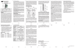
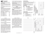
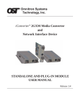
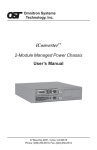
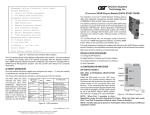
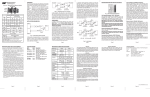
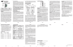
OVERVIEW:
The iConverter 100Fx/Tx converters support the IEEE
802.3 Ethernet standard and converts 100BASE-FX fiber
to 100BASE-TX unshielded twisted pair (UTP). Models
are available for multimode (MM) and single-mode (SM)
dual fiber and single-mode single-fiber.
iConverter® 100Fx/Tx User Manual
The 100Fx/Tx supports UTP Half-Duplex and Full-Duplex
auto-negotiation with manual override and features a
crossover UTP switch for easy attachment to hubs,
switches and workstations.
iConverter 100Fx/Tx Dual Fiber Modules
Connector Types
Fiber Type Distance
ST
SC
MT-RJ
LC
MM
5 km
8360-0
8362-0
8364-0
-
SM
30 km
8361-1
8363-1
8365-1
8367-1
SM
60 km
8361-2
8363-2
-
8367-2
SM
120 km
-
8363-3
-
8367-3
iConverter 100Fx/Tx SF Single-Fiber Modules
Fiber /
Connector
Type
Distance
Tx: 1310 nm,
Rx: 1550 nm
Tx: 1550 nm,
Rx: 1310 nm
SM / SC
20 km
8370-1
8371-1
SM / SC
40 km
8370-2
8371-2
For wide temperature (-40 to 60º C), add a "W" to the end of the model
number. Consult factory for extended temperature (-40 to +75º C) models.
When using single-fiber (SF) media converter models, the Tx wavelength on
one end has to match the Rx wavelength on the other.
The 100Fx/Tx can be used in an unmanaged or managed
fashion. When unmanaged, it can be installed in a
chassis without an iConverter Network Management
Module (NMM) or iConverter 10/100M2. To be managed,
an NMM module or 10/100M2 module must be installed in
the same chassis.
LINK MODES:
In order to accommodate different user needs, the
100Fx/Tx supports three different linking modes.
The Link Segment (LS) mode transmits a link signal
independently of any received link at any port. Utilizing
this configuration, a loss of a receive link signal will only
affect the port detecting the loss of signal. All the other
ports will continue to generate a link signal. For example
a loss of link on the fiber port only affects the fiber port;
the other ports remain unaffected [Fig 1(b)].
The Link Propagate (LP) mode transmits a link signal
only when a link signal is detected. Utilizing this
configuration, a loss of a receive link signal will continue
to propagate through to the next port in the network. For
Page 1
LED INDICATORS:
LED
Color Description
When in the UTP Manual Negotiate “Man” position, the
converter does not auto-negotiate and operates in the
duplex mode selected by the UTP Full/Half-Duplex
“FDX/HDX” DIP-Switch.
Pwr:
F/O Lk:
AN:
enabled
FDx:
UTP/Lk:
When the UTP Auto/Manual Negotiate “AN/Man”
DIP-Switch is in the Manual “Man” position, the UTP
Full/Half-Duplex “FDX/HDX” DIP-Switch determines the
duplex mode for the converter.
When the UTP Full/Half-Duplex DIP-Switch is in the
UTP Full-Duplex “FDX” position (factory setting), the
converter operates in Full-Duplex mode. When in the
UTP Half-Duplex “HDX” position, it operates in
Half-Duplex mode. Set the duplex mode to match the
connecting device and check for link status.
Note: Attaching an auto-negotiating UTP port to a
non-auto-negotiating (manual / forced / hard-coded)
UTP port may result in an unpredictable port setting
with excessive collisions and poor link performance.
When operating in Manual mode both mating ports
MUST be set manually to the same speed and duplex
mode.
RJ45 Crossover “= / X” Switch (Not Shown):
When connecting the UTP to a hub or switch, set this
front-plane switch to Straight-Through “=” (factory
setting). When connecting to a workstation, set it to
Crossover “X”.
Page 6
The Remote Fault Detection (RFD) mode transmits a
link signal only when a link signal is detected. When a
loss of link is detected, this mode will perform both a
loop back and propagate forward. For example, the
fiber fault is looped back in the opposite direction causing
the port on the other media converter to lose fiber link.
It also propagates the fault forward toward the UTP port
causing the switch port to lose link [Fig 1(d)].
Note: Connecting two converters set to RFD is an
illegal setting and will cause a “deadly embrace”
lockup.
Symmetrical Fault Detection is only supported on
modules with the revision of xx/08.
In Symmetrical Fault Detection (SFD), the UTP port
transmits a Link signal only when receiving a Link at the
fiber port. The fiber port transmits a Link signal only
when receiving a Link signal at both the fiber port and
the UTP port. As a result, fiber faults (no Link received
at the fiber) are looped back and can be reported to the
network core. In addition, connecting two back-to-back
converters which are both set to SFD facilitates dualloop-back, where fiber faults are reported to both ends
of the network link. A blinking fiber link LED on a
converter indicates a fault of the transmit fiber or UTP
cables of that converter [Fig. 1(e)].
Note: Converters in SFD mode must be deployed in
pairs.
Page 2
and matches the duplex mode of a mating
auto-negotiating device connected to its UTP port.
UTP Full/Half Duplex “FDX/HDX” DIP-Switch:
example, the fault at the fiber port is propagated forward
causing the switch port to drop its link due to the
propagated fault [Fig 1(c)].
Yellow On - Power on
Green On - Link; Blink - Activity
Green On - UTP Auto-Negotiation
Green
Green
On - Full-Duplex mode
On - UTP Link; Blink - Activity
Page 3
100Fx/Tx SPECIFICATIONS:
Protocols
Copper
Connectors
Fiber
Connectors
MOUNTING AND CABLE ATTACHMENT:
Controls
The iConverter modules are hot-swappable and can be
installed into any iConverter chassis.
LED Displays
1. Using the chassis module guides for alignment, insert
the module into the selected slot and secure using
the front panel fastener screw.
Note: Ensure that the module is firmly seated
against the backplane.
2. Using a Category 5 cable, attach the UTP port to a
100BASE-TX Ethernet device.
3. Using a multimode or single-mode dual-fiber cable as
required per the converter type, attach the fiber port
to a 100BASE-FX mating Ethernet device. The transmit
(Tx) must attach to the receive side of the mating
device and the receive (Rx) must attach to the transmit
side.
4. Single-fiber (SF) converters must be used in matched
pairs. The transmit (Tx) and receive (Rx) wavelengths
of one converter must match the receive (Rx) and
transmit (Tx) wavelengths of the mating converter.
For example, an 8370-1 must be connected to an
8371-1.
Page 7
100Fx/Tx
Model Type
Dimensions
100BASE-FX, 100BASE-TX
RJ-45
SC, ST, LC, MT-RJ, SFD
Single-Fiber SC
UTP X-over, LS/LP, RFD,
UTP FDX/HDX, UTP A/N
Power, FO link, UTP link,
Auto, FDX/HDX
W:0.85" x D:4.5" x H:2.8"
Weight
8 oz.
Compliance
UL, CE, FCC Class A,
NEBS Level 3
Power
Requirement
0.7A @ 3.3VDC (typical)
Temperature
Standard: 0 to 50º C
Wide: -40 to 60º C
Storage: -40 to 80º C
Humidity
5 to 95% (non-condensing)
Altitude
-100m to 4000m
MTBF (hrs)
730,000
Page 8
LS
(a)
Switch 1
FRONT PANEL DIP-SWITCH SETTINGS:
LS
Fiber
UTP
UTP
Fiber
Converter A
Converter B
LS
LS
Switch 2
Fig. 2 Front Panel DIP-Switches
(b)
Switch 1
Converter A
LP
Converter B
LP
Switch 2
Converter A
Converter B
Switch 2
SW1
SW2
LS
Normal
Link Segment (LS)
LP
Normal
Link Propagate (LP)
LS
RFD
Remote Fault Detection + LP
(RFD+LP)
LP
RFD
Illegal Setting
(c)
Switch 1
Fig. 3 Link Mode Selection Table
RFD+LP
LP
SW1
SW2
LS
Normal
Link Segment (LS)
LP
Normal
Link Propagate (LP)
LS
RFD
Remote Fault Detection + LP
(RFD+LP)
LP
RFD
Symmetrical Fault Detection (SFD)
(d)
Switch 1
Link Mode
Converter A
SFD
Converter B
SFD
Switch 2
(e)
Switch 1 Converter A
Converter B Switch 2
LED Lit
LED Blinking
LED Off
LED Status depends on connected device
Link Mode
Fig 4 Link Mode Selection Table for Revision xx/08
Fig. 1 Link Modes
UTP Auto/Manual Negotiate “AN/Man” DIP-Switch:
When this DIP-Switch is in the UTP Auto-Negotiate “AN”
position (factory setting), the converter auto- negotiates
Page 4
Page 5
Warning
equipment, Buyer-supplied interfacing, unauthorized
modifications or tampering with equipment (including
removal of equipment cover by personnel not
specifically authorized and certified by Omnitron), or
misuse, or operating outside the environmental
specification of the product (including but not limited to
voltage, ambient temperature, radiation, unusual dust,
etc.), or improper site preparation or maintenance.
The operating description in this Instruction Manual is for
use by qualified personnel only. To avoid electrical shock,
do not perform any servicing of this unit other than that
contained in the operating instructions, unless you are
qualified and certified to do so by Omnitron Systems
Technology, Inc.
Warranty
This product is warranted to the original purchaser against
defects in material and workmanship for a period of
TWO YEARS from the date of shipment. A LIFETIME
warranty may be obtained by the original purchaser by
REGISTERING this product with Omnitron within 90 days
from the date of shipment. TO REGISTER, COMPLETE
AND MAIL OR FAX THE ENCLOSED REGISTRATION
FORM TO THE INDICATED ADDRESS. Or you may
register your product on the Internet at www.omnitronsystems.com. During the warranty period, Omnitron will,
at its option, repair or replace a product which is proven
to be defective.
For warranty service, the product must be sent to an
Omnitron designated facility, at Buyer’s expense.
Omnitron will pay the shipping charge to return the product
to Buyer’s designated US address using Omnitron’s
standard shipping method.
No other warranty is expressed or implied. Omnitron
specifically disclaims the implied warranties of
merchantability and fitness for any particular purpose.
Exclusive Remedies
The remedies provided herein are the Buyer’s sole and
exclusive remedies. Omnitron shall not be liable for any
direct, indirect, special, incidental, or consequential
damages, whether based on contract, tort, or any legal
theory.
Technical Support:
For help with this product, contact our Technical Support:
Phone:
(949) 250-6510
Fax:
(949) 250-6514
Address:
Omnitron Systems Technology, Inc.
140 Technology Dr., #500
Irvine, CA 92618 USA
Limitation of Warranty
The foregoing warranty shall not apply to defects
resulting from improper or inadequate use and/or
maintenance of the equipment by Buyer, Buyer-supplied
Page 9
Email:
URL:
[email protected]
www.omnitron-systems.com
Form: 040-08360-001G 9/07
Page 10