1
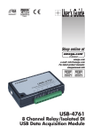
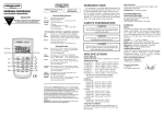
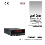
User’s Guide
Shop online at
omega.com
e-mail: [email protected]
For latest product manuals:
omegamanual.info
LV800 SERIES
Capacitance Point Level Sensors
OMEGAnet ® Online Service
omega.com
Internet e-mail
[email protected]
Servicing North America:
U.S.A.:
ISO 9001 Certified
Canada:
One Omega Drive, P.O. Box 4047
Stamford, CT 06907-0047
TEL: (203) 359-1660
e-mail: [email protected]
976 Bergar
Laval (Quebec) H7L 5A1, Canada
TEL: (514) 856-6928
e-mail: [email protected]
FAX: (203) 359-7700
FAX: (514) 856-6886
For immediate technical or application assistance:
U.S.A. and Canada: Sales Service: 1-800-826-6342 / 1-800-TC-OMEGA®
Mexico:
Benelux:
Czech Republic:
France:
Customer Service: 1-800-622-2378 / 1-800-622-BEST®
Engineering Service: 1-800-872-9436 / 1-800-USA-WHEN®
TELEX: 996404 EASYLINK: 62968934 CABLE: OMEGA
En Espan˜ol: (001) 203-359-7803
FAX: (001) 203-359-7807
e-mail: [email protected]
[email protected]
Servicing Europe:
Postbus 8034, 1180 LA Amstelveen, The Netherlands
TEL: +31 (0)20 3472121
FAX: +31 (0)20 6434643
Toll Free in Benelux: 0800 0993344
e-mail: [email protected]
Frystatska 184, 733 01 Karviná, Czech Republic
TEL: +420 (0)59 6311899
FAX: +420 (0)59 6311114
Toll Free: 0800-1-66342
e-mail: [email protected]
11, rue Jacques Cartier, 78280 Guyancourt, France
TEL: +33 (0)1 61 37 2900
FAX: +33 (0)1 30 57 5427
Toll Free in France: 0800 466 342
e-mail: [email protected]
Germany/Austria: Daimlerstrasse 26, D-75392 Deckenpfronn, Germany
TEL: +49 (0)7056 9398-0
Toll Free in Germany: 0800 639 7678
e-mail: [email protected]
FAX: +49 (0)7056 9398-29
United Kingdom: One Omega Drive, River Bend Technology Centre
ISO 9002 Certified
Northbank, Irlam, Manchester
M44 5BD United Kingdom
TEL: +44 (0)161 777 6611
FAX: +44 (0)161 777 6622
Toll Free in United Kingdom: 0800-488-488
e-mail: [email protected]
It is the policy of OMEGA Engineering, Inc. to comply with all worldwide safety and EMC/EMI
regulations that apply. OMEGA is constantly pursuing certification of its products to the European New
Approach Directives. OMEGA will add the CE mark to every appropriate device upon certification.
The information contained in this document is believed to be correct, but OMEGA accepts no liability for any
errors it contains, and reserves the right to alter specifications without notice.
WARNING: These products are not designed for use in, and should not be used for, human applications.
1
LV 8 0 0 S E R I E S
This manual contains the information necessary to ensure a safe and
successful installation. Please read and comply with the section on page
9 of this manual pertaining to SAFETY. Doing so will ensure proper operation of the equipment and the safety of all personnel.
Before discarding shipping container, please inspect it thoroughly and
verify that all parts ordered are accounted for. Sometimes smaller parts
become stuck under carton flaps and other packaging materials.
2
P R E - I N S TA L L AT I O N C O N S I D E R AT I O N S
Choosing a Location: (See Figure 2)
1) Material Flow - When selecting a location for the LV800,
choose a point in the vessel where the probe will be out of
the direct flow of incoming and outgoing material to prevent
any mechanical damage that may be caused by the pressure of the flow. The LV800 must be positioned at a point
where incoming material will reach and cover the probe in its
normal flow, and when receding, will flow away from the
probe in an even manner. For best results, choose a position where a majority of the probe, not just the tip, will be
covered. This is particularly important when detecting materials with low relative dielectric constants and low product
densities. The unit will not operate as a “tip sensitive”
device. For extended length models, allow for at least 8 to
12 inches (203-305 mm) of probe coverage. When sensing
highly conductive materials, or those with a high dielectric
constant, the LV800 can perform as a “tip sensitive” sensor.
2) Vessel Contact - Select an area where the probe can not
contact any internal structure elements of the vessel.
3) Driven Shield Penetration - Select a location which
ensures that the driven shield section protrudes into the vessel and is not recessed in the mounting neck.
4) Multiple Probe Proximity - If more than one sensor is
mounted in the vessel, do not place the sensors closer than
18 inches (457 mm) from one another.
Cover Removal: (See Figure 1)
Before loosening the cover, loosen or remove the cover lock
screw. Spanner slots are incorporated on the top of the cover
which should be used to loosen the cover from the housing.
Use a flat bar for initial loosening. DO NOT use a strap or chain
type wrench. Keep hands clear of threads on the cover and
housing to avoid contact with the thread lubricant.
Figure 2
Figure 1
3
M E C H A N I C A L I N S TA L L AT I O N
E L E C T R I C A L I N S TA L L AT I O N
Standard, Food Grade and Stub Probe Mounting:
(See Figures 3 & 4)
1) Select a mounting location in accordance with the PreInstallation Recommendations.
2) If using a welded fitting, cut a hole into the side/top of the
vessel corresponding to the mounting connection (1-1/4”
NPT or 3/4” NPT). If using a mounting plate, cut a 2-1/2 inch
(64 mm) center hole and six 11/32 inch(9mm) mounting
holes (for 5/16” bolts) on a 7 inch (178 mm)bolt circle. Use
mounting plate as a template.
3) Weld fitting or attach mounting plate to vessel wall.
4) Insert probe through fitting. Do not use sealant tapes (e.g.
Teflon tape) or putties. When using the 1-1/4” NPT
connection, grease threads with anti-seize then thread unit
tightly into place by gripping and rotating housing. When
using the 3/4” NPT connection, thread unit tightly into place
by gripping and rotating 15/16 inch (24 mm) wrench flats
provided on fitting. Continuity between sensor mounting
point and vessel wall must be maintained to assure proper
probe operation.
Factory Wiring:
The LV800 probe wires are connected to the backside of the
PCB. DO NOT alter this connection. Doing will likely cause
improper operation of the sensor.
Permanently Connected Equipment:
Disconnecting devices shall by included in the system installation. In installations were multiple circuits are used (i.e. independent circuits for power input and output relay), individual
disconnects are required. The disconnects shall be within
close proximity of the equipment, accessible to operators, and
marked appropriately as the disconnect for the associated circuit. Assure the disconnect ratings are appropriately sized for
the circuit protected (See Specifications).
Circuit Separation:
Two cable entry locations are provided to aid in maintaining
separation of "hazardous live" (typically mains voltages such as
115VAC and 230VAC) and limited circuits (typically control
voltages less than 30Vrms or 42.4VDC). However, since the
LV800 single wiring compartment can not absolutely protect
against physical contact between multiple circuits, it is required
that all wiring used must have an insulation rating of 300V minimum, and a temperature rating of 80˚ C (176˚ F) minimum.
DIMENSIONS ARE SHOWN IN INCHES WITH MILLIMETER EQUIVALENT IN BRACKETS
Protective Earthing:
Each LV800 is provided with a "protective conductor terminal"
which shall be terminated to the local earth ground potential to
eliminate shock hazard in the unlikely event of internal insulation breakdown. Select wire size that can carry in excess of the
sum of all circuit's maximum amperage.
Figure 3
Figure 4
4
Power Input: (See Figure5)
The LV800 is designed to accept either 115VAC or 230VAC
(factory set). Verify the intended voltage supply is compatible
with the voltage configuration indicated on the electronics and
the external nameplate. Connect power as shown in Figure 5.
Select wire size that can deliver suitable voltage and current for
the application.
2-Step Calibration- probe exposed to material
1) While the probe is not covered with material, rotate “Sense
Adjust” clockwise just until “Sense” (yellow) LED turns on.
2) Permit the application material to cover the probe. While
counting the number of revolutions, rotate “Sense
Adjust” counter-clockwise until the “Sense” (yellow) LED
turns off. Reposition “Sense Adjust” at the half way point
between the LED on and LED off settings. (e.g. After inserting the probe into the material, if it takes 2 counter-clockwise
turns of “Sense Adjust” for the “Sense” (yellow) LED to turn
off, then “Sense Adjust” should be repositioned 1 clockwise
turn.)
Output Relay Contacts: (See Figure 5)
The LV800 is equipped with one or two sets of isolated contacts
which indicates whether or not material is being detected within the vessel. This output is also influenced by the selection of
the "fail-safe" switch as described in the "Calibration" section of
this manual. The designations on the circuit board relate to the
contact status when the material is "not" sensed and the failsafe switch is in the "low" mode. These contacts can be connected to any type of control device, provided that ratings are
observed (See Specifications). Select wire size that can deliver suitable voltage and current for the application.
Figure 6
2-Step Calibration- probe exposed to free air only
1) Rotate “Sense Adjust” clockwise just until the “Sense”
(yellow) LED turns on.
2) Reposition “Sense Adjust” a number of turns counterclockwise with respect to the three described sensitivities
below (see Figure 7). It is desirable to reposition “Sense
Adjust” in accordance to “2-Step Calibration - probe
exposed to material” procedure once material can cover the
probe. Materials with high dielectric constants or conductivity, require the sensitivity adjustment further counterclockwise than those applications with low dielectric
constants.
Figure 5
C A L I B R AT I O N
Sensitivity: (See Figure 6)
Sensitivity is set in the field via a "Sense Adjust" 25-turn potentiometer.
The “Sense Adjust” tunes the sensitivity of the LV800 to the
material being sensed. Rotating the adjustment in a clockwise
direction will increase the sensitivity making the material easier
to “detect”. There are two different procedures which can be
used in the calibration process. Both utilize the simple “2-Step
Calibration” procedure. One procedure sets the sensitivity with
the probe being exposed to the material, while the second procedure exposes the probe to free air only. Since the capacitance being measured is directly related to the material being
sensed, the best results will be achieved by setting the calibration while the probe is exposed to the application material.
5
LV800
Figure 7
Delay:
A potentiometer is provided for setting the time delay between
the time material is "sensed" (Yellow LED on) and the time the
relay contact output changes (Red LED on). Units have a 1turn potentiometer. A clockwise rotation will increase the delay
from .25 to 15 seconds. This adjustment minimizes false signals associated with temporary material shifts. The delay
between the time material is "not sensed" (Yellows LED off)
and the time the relay contact output changes (Red LED off) is
fixed at .25 seconds.
Figure 9
2) Red LED - Its status describes the "operate/output" condition of the LV800. Illumination indicated the relay is in the
"operate/material sensed" condition. Its state is influenced
by the time delay setting but not by the fail-safe setting. This
LED is aimed at the lens in the cover so it can be seen with
the cover on or off.
3) Green LED - Its status indicates “no material sensed” condition of the LV800 in combination with the time delay setting. If material has not been sensed for a long enough
time (as set by the time delay setting), this LED will be illuminated. The red and green LEDs should never be illuminated at the same time. The green LED's state is not
affected by the fail-safe setting. This LED is also aimed at
the lens in the cover so that it can be seen with the cover
on or off.
Fail-safe: (see Figure 8)
The term fail-safe refers to the output signal condition which
occurs with a loss of power to the probe. A switch permits
selection of either low or high fail-safe.
High Fail-Safe: The relay will de-energize when material
is sensed at high level or with power loss.
Low Fail-Safe: The relay will de-energize when material
is below low level or with power loss. Note the designations
on the electronics label refer to the relay contact status
when no material is sensed and low fail-safe is selected
(Relay is de-energized). The designations are reversed
when no material is sensed and high fail-safe is selected
(Relay is energized).
Figure 8
Indicators: (See Figure 9)
1) Yellow LED - Its status describes the "sensing" condition of
the LV800. Illumination indicated that the amount of capacitance established by the "Sense Adjust" has been detected. Its status is not affected by the time delay setting of the
fail-safe setting. This LED can only be seen when the cover
has been removed.
6
TROUBLESHOOTING
MAINTENANCE
PROBLEM: Sensor will not sense material
CAUSE/SOLUTION:
1) Verify power is applied to the sensor.
2) Verify "Sense Adjust." Reposition adjustment clockwise
therefore making the probe more sensitive to "difficult to
sense" materials.
3) Verify probe coverage when sensing is expected. The sensor is not designed to be "tip sensitive." Permit significant
probe coverage before expecting material sensing.
4) Verify electrical continuity between sensor housing and vessel wall.
5) Verify connection of the electronic module to the probe.
Fuse Replacement:
The fuse incorporated into the LV800 PCB is not intended for
operator replacement. A qualified technician can replace the
applicable fuse according to the following specifications. If necessary, consult the factory for additional technical assistance or
for return of the LV800.
115VAC
F1: 5x20mm, 0.63A Time Lag (Slo-Blo), 250VAC
Littelfuse:
#218.063
Bussman:
#GDC-63mA
230VAC
F1: 5x20mm, 0.32A Time Lag (Slo-Blo), 250VAC
Littelfuse:
#218.032
Bussman:
#GDC-32mA
PROBLEM: Sensor remains in the "SENSE" mode even
when material is absent
CAUSE/SOLUTION:
1) Verify the active probe is not in direct contact with any internal vessel structure. If so, reposition sensor.
2) Verify "Sense Adjust" setting. Reposition adjustment
counter-clockwise therefore making the probe less sensitive
to "easy to sense" materials.
3) Verify there is not a large buildup of material between the
active probe and the probe housing. See "Cleaning" in the
"Maintenance" section of this bulletin.
Preventive Maintenance:
The LV800 design is virtually maintenance free. In typical
applications, once the sensor is properly calibrated, it will operate without any further attention. In abrasive applications,
probe condition should be periodically observed. Although the
probe's construction is made with high quality engineering plastics, heavy abrasion can wear away the probe's insulators. This
can influence the calibration and eventually lead to sensor failure. The electronics are housed in a weatherproof enclosure.
In addition the PCBs are conformal coated with a siliconebased material to further prevent electrical influence by condensation. The sensor electronics should periodically be
observed for any signs of contamination caused by improper
enclosure protection (i.e. insure cover is fully engaged, and that
wire entries are properly sealed.)
PROBLEM: Sensor does not seem to hold its calibration
CAUSE/SOLUTION:
1) Verify that the "sense adjust" is positioned at ideal point as
described in 2-Step Calibration procedure. Placing setting
too close to threshold can create nuisance false signals.
2) Maximize probe coverage of material being sensed.
"Difficult to detect" materials (i.e. low dielectric or light materials) are more easily detected when more probe is covered.
Avoid setups where "probe tip sensitivity" is required.
3) Insure electrical continuity between the probe's mounting
point (3/4" NPT or 1 1-4" NPT) and the bin wall. Sealant
tapes (i.e. Teflon tape) can electrically isolate these regions
and make sensing more difficult.
4) Assess the temperature swing that the electronics sees in
application. Applications with "difficult to detect" materials
and that experience a wide temperature swing are the most
vulnerable. Consult factory for support.
Cleaning Requirements:
Environmental and hazardous location protection is highly
dependent on the proper installation of the cover to the housing. A lubricant is applied to the housing/cover threads to
enhance ability to twist-on twist-off cover. Clean and re-lubricate threads if necessary to insure trouble-free operation. Do
not physically alter threads in anyway otherwise environmental
or hazardous location protection could be compromised.
The driven shield feature of the LV800 is designed to minimize
the need for cleaning the probe portion of the sensor. In applications where material build-up is so excessive that electronics
can not adequately compensate, probe cleaning may be necessary. If so, wipe the probe with a clean damp cloth from the
housing to the probe tip.
PROBLEM: Output contacts perform opposite of
designations (N/O, N/C)
CAUSE/SOLUTION:
1) Designations on PCB relate to relay status when in "FailSafe Low" mode and when no material is sensed. If "Failsafe High" mode is used, the designations are reversed.
Swap wire terminations of N/O and N/C if necessary.
Changing the fail-safe selection is not recommended.
7
MECHANICALS
DIMENSIONS ARE SHOWN IN INCHES WITH MILLIMETER EQUIVALENT IN BRACKETS
Standard Probe
Stub Probe
8
SAFETY
S P E C I F I C AT I O N S
115VAC (±15%); 2.5VA; 50/60Hz / 230VAC (±15%); 2.5VA; 50/60Hz
6562 ft (2000 m) max
II
4 (Reduced to 2 by enclosure) Suitable for indoor/outdoor use
-40˚ F (-40˚ C) to +150˚ F (+65˚ C)
To +176˚ F (+80˚ C) w/alum. mount (<104˚ F (40˚ C) ambient)
To +400˚ F (+204˚ C) w/SS mount (<122˚ F (50˚ C) ambient)
Output Relay:
SPDT, 5A @ 250VAC, 30VDC maximum
External Indicators:
Red and green LEDs indicating power and operating mode
Sensitivity:
Multi-turn potentiometer adjustment 0.5pf to 150 pf
±0.015pf
per degree F (±0.027pf per degree C) @ 0.5pf setting
Stability:
Time Delay:
0.25 to 15 sec delay-to-activate, adjustable
0.25 sec delay-to-deactivate, fixed
Fail-Safe:
Switch selectable - HI/LO
Build-up Immunity:
Protected via driven shield to 150 ohm load
Enclosure:
Cast alum screw-on cover, beige polyester pwdr coat, NEMA 4, IP66
Conduit Connection: Two (2) 3/4” NPT connections
**Approvals:
CSAUS CSAC Ordinary Locations, CE Mark(Ordinary location only)
Standard/Food Grade Probe
Mounting:
1-1/4” NPT alum or combo 3/4” NPT 316SS and 1-1/4” NPT alum
Probe Material:
3/8in(9.5mm) dia. 316SS probe & guard, PPS insulators
Probe Length:
16in(406mm) from alum mounting
Temp (Probe Only): PPS +450˚ F (+232˚ C) max;
Pressure:
50 psi(3.5 bar) max (alum connection);150 psi(10 bar) max (3/4” NPT SS)
Stub Probe
Mounting:
1-1/4” NPT alum, or combo
3/4” NPT 316SS and 1-1/4” NPT alum
Probe Material:
3/8in(9.5mm) dia. 316SS probe & guard, PPS insulators
Probe Length:
Cut to customer specification; application dependent
Temp (Probe Only): PPS +450˚ F (+232˚ C) max
Pressure:
50 psi(3.5 bar) max (aluminum); 150 psi(10 bar) max (3/4 NPT SS)
Power:
Altitude:
Installation Category:
Pollution Degree:
Ambient Op Temp:
*Internal Bin Temp:
General Safety
CAUTION: It is essential that all instructions in this manual be followed to
ensure proper operation of the equipment and safety of operating personnel. Use of equipment not specified herein, may impair protection provided by equipment. The use of this symbol is used throughout manual to
highlight important safety issues. Please pay particular attention to these
items.
Electrical Shock Caution
Certain LV800 models are powered with HIGH VOLTAGE. No operator
serviceable parts are inside. All servicing is to be performed by qualified
personnel. Each MK-2e is provided with a "protective conductor terminal"
which shall be terminated to earth ground potential (See Electrical
Installation). This product's design complies with EN61010-1 installation
category II and pollution degree 2.
Electromagnetic Compatibility (EMC)
The LV800 was tested and found to comply with the standards listed
below. The LV800 should not be used in residential or commercial environments. Compliance to EMC standards was demonstrated by means of
a test setup using the following installation methods.
1) LV800 enclosure was connected to earth ground (protective
earth).
2) No specific wiring convention was used to supply power or
to retrieve output signal from the LV800.
EMC Emissions:
Meets EN 61326-1
EN 55011
EN 61000-3
Meets FCC Part 15B:
CISPR 11
EMC Immunity:
Meets EN 61326-1
IEC 1000-4-2
IEC 1000-4-3
IEC 1000-4-4
IEC 1000-4-5
IEC 1000-4-6
IEC 1000-4-8
IEC 1000-4-11
*Influenced by mounting, material thermal conductivity and ambient temperature.
Electrical Equipment for Control Use, EMC
Radiated and conducted emissions
(Class A- industrial)
Fluctuations/Flicker
RF Devices, Unintentional Radiators
Radiated and conducted emissions
(Class A- industrial)
Electrical Equipment for Control Use,
EMC
Electrostatic discharge (industrial)
RF radiated EM fields (industrial)
Electrical fast transients (industrial)
Electrical surges (industrial)
RF conducted EM energy (industrial)
Power frequency magnetic fields
(industrial)
Source voltage deviation
9
WARRANTY/DISCLAIMER
OMEGA ENGINEERING, INC. warrants this unit to be free of defects in materials and workmanship for a
period of 13 months from date of purchase. OMEGA’s WARRANTY adds an additional one (1) month
grace period to the normal one (1) year product warranty to cover handling and shipping time. This
ensures that OMEGA’s customers receive maximum coverage on each product.
If the unit malfunctions, it must be returned to the factory for evaluation. OMEGA’s Customer Service
Department will issue an Authorized Return (AR) number immediately upon phone or written request.
Upon examination by OMEGA, if the unit is found to be defective, it will be repaired or replaced at no
charge. OMEGA’s WARRANTY does not apply to defects resulting from any action of the purchaser, including but not limited to mishandling, improper interfacing, operation outside of design limits,
improper repair, or unauthorized modification. This WARRANTY is VOID if the unit shows evidence of
having been tampered with or shows evidence of having been damaged as a result of excessive corrosion;
or current, heat, moisture or vibration; improper specification; misapplication; misuse or other operating
conditions outside of OMEGA’s control. Components in which wear is not warranted, include but are not
limited to contact points, fuses, and triacs.
OMEGA is pleased to offer suggestions on the use of its various products. However,
OMEGA neither assumes responsibility for any omissions or errors nor assumes liability for any
damages that result from the use of its products in accordance with information provided by
OMEGA, either verbal or written. OMEGA warrants only that the parts manufactured by the
company will be as specified and free of defects. OMEGA MAKES NO OTHER WARRANTIES OR
REPRESENTATIONS OF ANY KIND WHATSOEVER, EXPRESSED OR IMPLIED, EXCEPT THAT OF
TITLE, AND ALL IMPLIED WARRANTIES INCLUDING ANY WARRANTY OF MERCHANTABILITY
AND FITNESS FOR A PARTICULAR PURPOSE ARE HEREBY DISCLAIMED. LIMITATION OF
LIABILITY: The remedies of purchaser set forth herein are exclusive, and the total liability of
OMEGA with respect to this order, whether based on contract, warranty, negligence,
indemnification, strict liability or otherwise, shall not exceed the purchase price of the
component upon which liability is based. In no event shall OMEGA be liable for
consequential, incidental or special damages.
CONDITIONS: Equipment sold by OMEGA is not intended to be used, nor shall it be used: (1) as a “Basic
Component” under 10 CFR 21 (NRC), used in or with any nuclear installation or activity; or (2) in medical
applications or used on humans. Should any Product(s) be used in or with any nuclear installation or
activity, medical application, used on humans, or misused in any way, OMEGA assumes no responsibility
as set forth in our basic WARRANTY/DISCLAIMER language, and, additionally, purchaser will indemnify
OMEGA and hold OMEGA harmless from any liability or damage whatsoever arising out of the use of the
Product(s) in such a manner.
RETURN REQUESTS/INQUIRIES
Direct all warranty and repair requests/inquiries to the OMEGA Customer Service Department. BEFORE
RETURNING ANY PRODUCT(S) TO OMEGA, PURCHASER MUST OBTAIN AN AUTHORIZED RETURN
(AR) NUMBER FROM OMEGA’S CUSTOMER SERVICE DEPARTMENT (IN ORDER TO AVOID
PROCESSING DELAYS). The assigned AR number should then be marked on the outside of the return
package and on any correspondence.
The purchaser is responsible for shipping charges, freight, insurance and proper packaging to prevent
breakage in transit.
FOR WARRANTY RETURNS, please have the
following information available BEFORE
contacting OMEGA:
1. Purchase Order number under which the product was PURCHASED,
2. Model and serial number of the product under
warranty, and
3. Repair instructions and/or specific problems
relative to the product.
FOR NON-WARRANTY REPAIRS, consult OMEGA
for current repair charges. Have the following
information available BEFORE contacting OMEGA:
1. Purchase Order number to cover the COST
of the repair,
2. Model and serial number of the product, and
3. Repair instructions and/or specific problems
relative to the product.
OMEGA’s policy is to make running changes, not model changes, whenever an improvement is possible. This affords our
customers the latest in technology and engineering.
OMEGA is a registered trademark of OMEGA ENGINEERING, INC.
© Copyright 2005 OMEGA ENGINEERING, INC. All rights reserved. This document may not be copied, photocopied, reproduced, translated, or reduced to any electronic medium or machine-readable form, in whole or in part, without the prior
written consent of OMEGA ENGINEERING, INC.
10
Where Do I Find Everything I Need for
Process Measurement and Control?
OMEGA…Of Course!
Shop online at omega.com
TEMPERATURE
M
U
M
U
M
U
M
U
M
U
Thermocouple, RTD & Thermistor Probes, Connectors, Panels & Assemblies
Wire: Thermocouple, RTD & Thermistor
Calibrators & Ice Point References
Recorders, Controllers & Process Monitors
Infrared Pyrometers
PRESSURE, STRAIN AND FORCE
M
U
M
U
M
U
M
U
Transducers & Strain Gages
Load Cells & Pressure Gages
Displacement Transducers
Instrumentation & Accessories
FLOW/LEVEL
M
U
M
U
M
U
M
U
Rotameters, Gas Mass Flowmeters & Flow Computers
Air Velocity Indicators
Turbine/Paddlewheel Systems
Totalizers & Batch Controllers
pH/CONDUCTIVITY
M
U
M
U
M
U
M
U
pH Electrodes, Testers & Accessories
Benchtop/Laboratory Meters
Controllers, Calibrators, Simulators & Pumps
Industrial pH & Conductivity Equipment
DATA ACQUISITION
M
U
M
U
M
U
M
U
M
U
Data Acquisition & Engineering Software
Communications-Based Acquisition Systems
Plug-in Cards for Apple, IBM & Compatibles
Datalogging Systems
Recorders, Printers & Plotters
HEATERS
M
U
U
M
M
U
U
M
U
M
Heating Cable
Cartridge & Strip Heaters
Immersion & Band Heaters
Flexible Heaters
Laboratory Heaters
ENVIRONMENTAL
MONITORING AND CONTROL
M
U
M
U
M
U
U
M
M
U
U
M
Metering & Control Instrumentation
Refractometers
Pumps & Tubing
Air, Soil & Water Monitors
Industrial Water & Wastewater Treatment
pH, Conductivity & Dissolved Oxygen Instruments
M-4168/0405