1
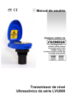
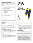
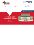
MAD
IN
USA
WARRANTY / DISCLAIMER
OMEGA ENGINEERING, INC. warrants this unit to be free of defects in materials and workmanship for a period of 13 months from date of purchase. OMEGA’s Warranty adds an additional one (1) month grace period
to the normal one (1) year product warranty to cover handling and shipping time. This ensures that
OMEGA’s customers receive maximum coverage on each product.
If the unit malfunctions, it must be returned to the factory for evaluation. OMEGA’s Customer Service
Department will issue an Authorized Return (AR) number immediately upon phone or written request. Upon
examination by OMEGA, if the unit is found to be defective, it will be repaired or replaced at no charge.
OMEGA’s WARRANTY does not apply to defects resulting from any action of the purchaser, including but not
limited to mishandling, improper interfacing, operation outside of design limits, improper repair, or unauthorized modification. This WARRANTY is VOID if the unit shows evidence of having been tampered with or
shows evidence of having been damaged as a result of excessive corrosion; or current, heat, moisture or vibration; improper specification; misapplication; misuse or other operating conditions outside of OMEGA’s control.
Components which wear are not warranted, including but not limited to contact points, fuses, and triacs.
OMEGA is pleased to offer suggestions on the use of its various products. However, OMEGA
neither assumes responsibility for any omissions or errors nor assumes liability for any damages
that result from the use of its products in accordance with information provided by OMEGA,
either verbal or written. OMEGA warrants only that the parts manufactured by it will be as
specified and free of defects. OMEGA MAKES NO OTHER WARRANTIES OR REPRESENTATIONS
OF ANY KIND WHATSOEVER, EXPRESS OR IMPLIED, EXCEPT THAT OF TITLE, AND ALL IMPLIED
WARRANTIES INCLUDING ANY WARRANTY OF MERCHANTABILITY AND FITNESS FOR A
PARTICULAR PURPOSE ARE HEREBY DISCLAIMED. LIMITATION OF LIABILITY: The remedies of
purchaser set forth herein are exclusive, and the total liability of OMEGA with respect to this
order, whether based on contract, warranty, negligence, indemnification, strict liability or
otherwise, shall not exceed the purchase price of the component upon which liability is based. In
no event shall OMEGA be liable for consequential, incidental or special damages.
CONDITIONS: Equipment sold by OMEGA is not intended to be used, nor shall it be used: (1) as a “Basic
Component” under 10 CFR 21 (NRC), used in or with any nuclear installation or activity; or (2) in medical
applications or used on humans. Should any Product(s) be used in or with any nuclear installation or activity,
medical application, used on humans, or misused in any way, OMEGA assumes no responsibility as set forth
in our basic WARRANTY/ DISCLAIMER language, and, additionally, purchaser will indemnify OMEGA and
hold OMEGA harmless from any liability or damage whatsoever arising out of the use of the Product(s) in
such a manner.
RETURN REQUESTS / INQUIRIES
omega.com
®
®
OMEGAnet ® On-Line Service
www.omega.com
Internet e-mail
[email protected]
Servicing North America:
Canada:
976 Bergar
Laval (Quebec) H7L 5A1, Canada
Tel: (514) 856-6928
FAX: (514) 856-6886
e-mail: [email protected]
USA: ISO 9001 Certified
One Omega Drive, Box 4047
Stamford CT 06907-0047
Tel: (203) 359-1660
FAX: (203) 359-7700
e-mail: [email protected]
For immediate technical or application assistance:
USA and Canada:
Sales Service: 1-800-826-6342 / 1-800-TC-OMEGA®
Customer Service: 1-800-622-2378 / 1-800-622-BEST ®
Engineering Service: 1-800-872-9436 / 1-800-USA-WHEN®
TELEX: 996404 EASYLINK: 62968934
CABLE: OMEGA
Mexico:
~ol: (001) 203-359-7803
En Espan
FAX: (001) 203-359-7807
e-mail: [email protected]
[email protected]
Servicing Europe:
United Kingdom: ISO 9002 Certified
Frystatska 184/46, 733 01 Karvina´, Czech Republic
Tel: +420 (0)59 6311899
FAX: +420 (0)59 6311114
Toll Free: 0800-1-66342
e-mail: [email protected]
Daimlerstrasse 26, D-75392
Deckenpfronn, Germany
Tel: +49 (0)7056 9398-0
FAX: +49 (0)7056 9398-29
Toll Free in Germany: 0800 639 7678
e-mail: [email protected]
Postbus 8034, 1180 LA Amstelveen
The Netherlands
Tel: +31 (0)20 3472121 FAX: +31 (0)20 6434643
Toll Free in Benelux: 0800 0993344
e-mail: [email protected]
Germany/Austria:
Benelux:
Czech Republic:
One Omega Drive
River Bend Technology Centre
Northbank, Irlam
Manchester M44 5BD
United Kingdom
Tel: +44 (0)161 777 6611
FAX: +44 (0)161 777 6622
France:
11, rue Jacques Cartier
78280 Guyancourt, France
Tel: +33 (0)1 61 37 29 00 FAX: +33 (0)1 30 57 54 27
Toll Free in France: 0800 466 342
e-mail: [email protected]
M-3949/0403
Direct all warranty and repair requests/inquiries to the OMEGA Customer Service Department. BEFORE
RETURNING ANY PRODUCT(S) TO OMEGA, PURCHASER MUST OBTAIN AN AUTHORIZED RETURN (AR)
NUMBER FROM OMEGA’S CUSTOMER SERVICE DEPARTMENT (IN ORDER TO AVOID PROCESSING
DELAYS). The assigned AR number should then be marked on the outside of the return package and on
any correspondence. The purchaser is responsible for shipping charges, freight, insurance and proper packaging
to prevent breakage in transit.
FOR NON-WARRANTY REPAIRS, consult
FOR WARRANTY RETURNS, please have the
OMEGA for current repair charges. Have the folfollowing information available BEFORE contacting
lowing information available BEFORE contacting
OMEGA:
OMEGA:
1. Purchase Order number under which the product
1. Purchase Order number to cover the COST
was PURCHASED,
of the repair,
2. Model and serial number of the product under
2. Model and serial number of the product, and
warranty, and
3. Repair instructions and/or specific problems
3. Repair instructions and/or specific problems
relative to the product.
relative to the product.
Toll Free in United Kingdom:
0800-488-488
e-mail: [email protected]
It is the policy of OMEGA to comply with all worldwide safety and EMC/EMI regulations that apply. OMEGA
is constantly pursuing certification of its products to the European New Approach Directives. OMEGA will
add the CE mark to every appropriate device upon certification.
The information contained in this document is believed to be correct, but OMEGA Engineering, Inc. accepts no liability for any errors it
contains, and reserves the right to alter specifications without notice.
WARNING: These products are not designed for use in, and should not be used for, human applications.
Metering & Control Instrumentation
Refractometers
Pumps & Tubing
Air, Soil & Water Monitors
Industrial Water & Wastewater Treatment
pH, Conductivity & Dissolved Oxygen Instruments
OMEGA’s policy is to make running changes, not model changes, whenever an improvement is possible.
This affords our customers the latest in technology and engineering.
OMEGA is a registered trademark of OMEGA ENGINEERING, INC.
© Copyright 2003 OMEGA ENGINEERING, INC. All rights reserved. This document may not be copied, photocopied, reproduced, translated, or reduced to any electronic medium or machine-readable form, in whole or in part,
without the prior written consent of OMEGA ENGINEERING, INC.
䡺
⻬
䡺
⻬
䡺
⻬
䡺
⻬
䡺
⻬
䡺
⻬
Non-Intrusive Capacitance Switch
LVP-51 Series
ENVIRONMENTAL
MONITORING AND CONTROL
䡺
⻬
䡺
⻬
䡺
⻬
䡺
⻬
䡺
⻬
Heating Cable
Cartridge & Strip Heaters
Immersion & Band Heaters
Flexible Heaters
Laboratory Heaters
HEATERS
䡺
⻬
䡺
⻬
䡺
⻬
䡺
⻬
䡺
⻬
Data Acquisition & Engineering Software
Communications-Based Acquisition Systems
Plug-in Cards for Apple, IBM & Compatibles
Datalogging Systems
Recorders, Printers & Plotters
DATA ACQUISITION
䡺
⻬
䡺
⻬
䡺
⻬
䡺
⻬
pH Electrodes, Testers & Accessories
Benchtop/Laboratory Meters
Controllers, Calibrators, Simulators & Pumps
Industrial pH & Conductivity Equipment
pH/CONDUCTIVITY
䡺
⻬
䡺
⻬
䡺
⻬
䡺
⻬
http://www.omega.com
e-mail: [email protected]
Rotameters, Gas Mass Flowmeters & Flow Computers
Air Velocity Indicators
Turbine/Paddlewheel Systems
Totalizers & Batch Controllers
FLOW/LEVEL
䡺
⻬
䡺
⻬
䡺
⻬
䡺
⻬
“
Transducers & Strain Gauges
Load Cells & Pressure Gauges
Displacement Transducers
Instrumentation & Accessories
PRESSURE, STRAIN AND FORCE
䡺
⻬ Thermocouple, RTD & Thermistor Probes,
Connectors, Panels & Assemblies
䡺
⻬ Wire: Thermocouple, RTD & Thermistor
䡺
⻬ Calibrators & Ice Point References
䡺
⻬ Recorders, Controllers & Process Monitors
䡺
⻬ Infrared Pyrometers
TEMPERATURE
Where Do I Find Everything I Need for
Process Measurement and Control?
OMEGA…Of Course!
User’s Guide
SPECIFICATIONS
Contact output:
Process temp.:
Cable jacket mat.:
Cable type:
Cable length:
Classification:
CE compliance:
4-20 mA Sensor
Electrical Loading Limits
1,600
1,400
1,200
1,000
Unacceptable
Range
800
600
Acceptable
Range
400
200
0
12
18
24
30
Supply Voltage (VDC)
36
Maximum Tem. / Voltage Derating
Continuous 20 mA Sinking Curve
100
Unacceptable
Range
80
60
40
Acceptable
Range
20
00
-20
12
16
20
24
28
32
Operating Voltage (VDC)
36
Technology:
The non-intrusive RF capacitance switch detects the presence of liquid or air by measuring the conductive or dielectric values which are present in all materials. An electrical
capacitor is formed between the level switch and the outer
tank wall. As liquid rises and falls against the inner wall, the
capacitance effect is greatly increased and the 1A SPST
relay changes state.
2.2"(56mm)
Enclosure rating:
Enclosure mat.:
Conduit entrance:
Bracket material:
Bracket mounting:
Non-intrusive
Non-metallic
< 1" (25 mm)
± 1 mm in water
± 0.5 mm in water
> 10 constants
> 100 micromhos
12-36 VDC
25 mA maximum
(1) SPST relay
120 VAC/VDC @ 1A
(CE: 60 VAC/VDC @ 1A)
Selectable NO/NC
F: -40˚ to 194˚
C: -40˚ to 90˚
NEMA 4X (IP65)
PSO
Single, 1/2" NPT
PE
3M adhesive / plastic
thermal weld
PP
4-conductor, #22 AWG
(shielded)
Standard: 10' (3m)
General purpose
EN 50082-2 immunity
EN 55011 emission
EN 61010-1 safety
Max. Series Resistance (Ohms)
Tank mounting:
Tank mat. comp.:
Tank wall thick.:
Accuracy:
Repeatability:
Dielectric range:
Conductive range:
Supply voltage:
Consumption:
Contact type:
Contact rating:
Ambient Sensor Temperature (¡C)
Step One
1.0"
(25mm)
RELAY
Red (+)
Black (-)
White NO/NC
Green COM
Shld
3.2"(81mm)
1.6"(41mm)
8’ Cable (2.5m)
1.7" (44mm)
2.8" (71mm)
Table of Common Dielectric Constants:
NOTE: Liquids with a conductivity value > 100 µU are fine if coating is not an issue. Liquids with a dielectric constant less than 20 may not be reliably detected by an LVP-51 series level switch, depending on conditions.
Acetone
21
Acetoaldehyde
22.2
Acetyl methyl hexyl
ketone
28
Alcohol
16 to 31
Ammonia
15 to 25
Acetic acid
4.1 to 6.2
Butyl chloride
9.6
Barium chloride 9 to 11
Benzene
2.3
Benzine
2.3
Barium nitrate
5.6
Bromine
3.1
Chlorobenzene 4.7 to 6
Chlorotoluene
4.7
Chloroform
4.5 to 5.0
Chlorine, liquid
2.0
Carbon tetrachloride 2.2
Cyan
2.6
Cyclohexanemethanol 3.7
D.I. Water
20
Ethyl toluene
2.2
Ethyl alcohol
23
Ethylene glycol
37
Ethylene oxide
14
Ethylene dichloride
11 to 17
Ethylene chloride 10.5
Ethyl acetate
6.4
Ethyl salicylate
8.6
Ethyl stearate
2.9
Ethyl silicote
4.1
Formic acid
59
Ferric oleate
2.6
Freon
2.2
Glycerine
47
Glycol
30
Glycol nitrite
27
Gasoline
2 to 2.2
Hydrochloric acid
4.6
Isobutyric acid
2.7
Isobutyl methyl ketone 13
Jet fuel
1.7
Lead carbonate
18
Lead nitrate
38
Methyl salicylate
9.0
Methanol
33
Methyl alcohol 33 to 38
Margarine,liquid 2.8 to 3.2
Methyl acetate
7.3
N-butyl formate
2.4
Nitrobenzene
26 to 35
Nitrotoluene
25
Naphthalene 2.3 to 2.5
Oils, vegetable 2.5 to 3.5
Oils, mineral 2.3 to 2.4
Oils, petroleum 1.8 to 2.2
Oleic acid
2.5
Propane, liquid 1.8 to 1.9
Potassium nitrate
5.0 to 5.9
Potassium chloride 5.0
Stearic acid
2.3
Toluene
2.4
Trichloroethylene
3.4
Trichloroacetic acid 4.5
Terephthalic acid
1.5 to 1.7
Thinner
3.7
Urea
3.5
Vinyl chloride 2.8 to 6
Vinyl alcohol 1.8 to 2.0
Water, 20°C
80
Water, 100°C
48
SAFETY PRECAUTIONS
Step Two
INTRODUCTION
Step Three
About this Manual:
About Non-Intrusive RF Capacitance Technology:
PLEASE READ THE ENTIRE MANUAL PRIOR TO
INSTALLING OR USING THIS PRODUCT. This manual
includes information on all models of the LVP-51 series NonIntrusive RF Capacitance level switch from Omega. Please refer to
the part number located on the switch label to verify the exact
model which you have purchased.
OMEGA's LVP-51 series level switch generates a high radio frequency signal from the capacitance electrode on the tank side of each sensor. Depending on the thickness of the tank wall and the material of
which it is made, there is a particular minimum dielectric value the
electrode measures when there is no liquid on the other side of the
tank wall from the sensor. When liquid is on the other side of the
wall, the dielectric value rises.
User’s Responsibility for Safety:
Omega manufactures a wide range of liquid level sensors and technologies. While each of these sensors is designed to operate in a wide
variety of applications, it is the user’s responsibility to select a sensor
model that is appropriate for the application, install it properly, perform tests of the installed system, and maintain all components. The
failure to do so could result in property damage or serious injury.
Proper Installation and Handling:
Because this is an electrically operated device, only properlytrained staff should install and/or repair this product. The adhesive
on the fitting is for temporary installation only. For permanent
installation, the fitting for the sensor should be welded, glassed or
strapped to the tank itself using approved plastic welding techniques. Do not install the LVP-51 series sensor on a metal tank, or
within 6" of any metal pipe or fitting.
Mounting Bracket:
The LVP-51 series sensor may be mounted in the PE bracket (polyethylene, colored white). Make sure that the fitting is compatible
with the tank it will be applied to.
Material Compatibility:
The sensor itself is not designed to be immersed. It should be
mounted in such a way that it does not normally come into contact
with fluid. Its case is made out of Polysulfone (PSO). Refer to an
industry reference to ensure that compounds that may splash onto
the controller housing will not damage it. Such damage is not covered by the warranty.
Wiring and Electrical:
The supply voltage used to power the LVP-51 series sensor should
never exceed a maximum of 36 volts DC. Electrical wiring of the
sensor should be performed in accordance with all applicable
national, state, and local codes.
Flammable, Explosive and Hazardous Applications:
The LVP-51 series switch is not rated for use in hazardous locations. Refer to the National Electric Code (NEC) for all applicable
installation requirements in hazardous locations. DO NOT USE
THE LVP-51 SERIES GENERAL PURPOSE SWITCH IN HAZARDOUS LOCATIONS.
WARNING
Do not install the LVP-51 series level switch on a metallic tank,
or within 6" of any metallic object. Metal will adversely affect
the dielectric sensitivity of the sensor.
OMEGA's LVP-51 series sensors are not recommended for use
with electrically charged application liquids. For most reliable
operation, the liquid being measured may need to be electrically
grounded.
As part of installation, a two-step calibration procedure ensures that
the threshold between wet and dry is set at the ideal point for your
particular tank and application fluid, without the use of any external
test equipment. The sensor’s operation and point of actuation may
vary based on the dielectric properties of various application liquids,
tank materials and thicknesses. The LVP-51 series sensor is intended
to be used with liquids with a dielectric value between 20 and 80.
Due to its user calibration capability it may be able to detect liquids
below a dielectric constant of 20 under certain conditions, but this
must be verified by experimentation.
INSTALLATION
ELECTRICAL
Step Four
Step Five
OMEGA's LVP-51 series level switch may be installed anywhere on
a tank wall using the supplied PE fitting that the switch slides into.
The fitting comes with adhesive on the tank side that is sufficient to
hold the sensor in position temporarily while the installation is tested,
but for permanent installation the fitting must be welded, glassed or
strapped to the tank. Extra fittings are available from Omega, so that
the level switch may be moved to different locations on the tank by
sliding it into other fittings.
Supply Voltage:
Required Cable Length:
Attach the fitting to the tank:
1. Determine the mounting location for the level switch. The point
of actuation (where the sensor will send a “wet” signal) is most
often at the center of the sensor;
however the actual Point of
Actuation (POA) may differ
Weld
Fitting
depending on the application liquid and tank wall characteristics.
After positioning the fitting to
check clearances, etc., remove the
Sensor
paper protective strips from the
adhesive of the fitting.
2. Press the fitting into place. The
adhesive provides a seal between
the sensor and the tank wall, and
will hold it in place during testing
and installation.
The supply voltage to the LVP-51 series level switch should never
exceed a maximum of 36 VDC. Omega controllers have a built-in 13.5
VDC power supply which provides power to all of OMEGA's electrically powered sensors. Alternative controllers and power supplies, with
a minimum output of 12 VDC up to a maximum output of 36 VDC,
may also be used with the LVP-51 series level switch.
Determine the length of cable required between the LVP-51 series
level switch and its point of termination. Allow enough slack to
ensure the easy installation, removal and/or maintenance of the sensor. The cable length may be extended up to a maximum of 1000 feet,
using a well-insulated, 14 to 20 gauge shielded four conductor cable.
Wire Stripping:
Using a 10 gauge wire stripper, carefully remove the outer layer of
insulation from the last 1-1/4" of the sensor's cable. Unwrap and discard the exposed foil shield from around the signal wires, leaving the
drain wire attached if desired. With a 20 gauge wire stripper, remove
the last 1/4" of the colored insulation from the signal wires.
Screw
1/2" NPT
Connector
If desired, the sensor may be installed temporarily without welding the fitting to the wall. If several different locations must be
tried before permanent installation, use double-sided foam stick
tape designed for PE, for example Arclad type PE-6024,
CO#7331 (from Adhesive Research Inc., Glen Rock PA 17327) or
equivalent.
3. After the sensor has been tested to verify the POA, weld, glass or
strap the fitting to the tank using standard industrial plastic techniques.
Special note for small round tanks:
The fitting may be attached to small, round tanks, as long as the
majority of the fitting is firmly attached to the wall. However,
extreme installations may effect the switches performance.
Mount the sensor in the fitting:
1. Slide the sensor into the fitting.
2. After trimming the sensor wire to length if needed by the installation, thread the sensor wire into a plastic flexible conduit with a
1/2" male fitting. Screw the conduit into the sensor, being careful
not to cross the threads. Do not over tighten the conduit in the
sensor as this may break the fitting. Such damage is not covered
by the warranty. Take care while pulling the wire through conduit
that no excessive tension is placed on the sensor end of the wire,
so that the wire is not broken from the sensor housing.
3. Connect the sensor wire to the controller following the instructions in its manual. See the following Wiring Section for detailed
wiring instructions.
Signal Outputs (Current sensing):
The standard method used by Omega controllers; this technology uses
only two wires (Red and Black). The sensor draws 5 mA when it is dry,
and 19 mA when wet. NC/NO status must be set by the controller. The
Green and White wires are not used.
Red
+
-
Shield
Ground
Black
+
24 VDC
Power Supply
Multimeter
(mA)
Signal Outputs (Relay switching):
Allows the sensor to switch a small load on or off directly, using an
internal 1 A relay (60 VAC/60 VDC). All models, LVP-51 series_005, use the relay and features 4 wires (red, black, white and green)
and a shield wire. The NO/NC status is set by the polarity of the voltage feeding the Red and Black wires. The Green wire is the common
for the relay and the White is the NO or NC, depending on the polarity of Red and Black.
Normally Open Wiring:
Red
Black
Shield
Ground
White
Green
+
+
24 VDC
Power Supply
Multimeter
(Continuity)
Normally Open Wiring:
Black
Red
Shield
Ground
White
Green
+
+
24 VDC
Power Supply
Multimeter
(Continuity)
WIRING
WIRING
Step Six
Step Seven
Wiring to a Omega Controller
Wiring the Relay Output:
LVCN-120/-130/-140 Series Controller:
The LVP-51 series relay output can be wired as a dry contact to a
VDC or VAC power source. LVP-51 series requires 12 - 36 VDC
power to operate the sensor and switch the relay. All illustrations
below identify a Dry switch state as the normal position of the relay.
POWER
I N V E RT
D E L AY
--+
I N V E RT D E L AY
--+
R E L AY 1
Switching a Normally Open DC Load:
The Red wire connects to Positive (+) of the power supply and the
Black wire connects to Negative (-). The LOAD can be attached to
either the Green or White wires. Complete the circuit by either connecting the Green to (+) VDC power or White to (-) VDC power (see
illustration below).
R E L AY 2
L AT C H
INPUT 1
INPUT 2A
ON OFF
INPUT 2B
Red
Black
Shield
White and Green - Not Used
[Dry Condition]
Sensor
(NO)
Wiring as a P-Channel or N-Channel output:
The LVP-51 series can be substituted for either a P-Channel (PNP,
sourcing) output or a N-Channel (NPN, sinking) output.
Normally Open DC Load as a P-Channel Output:
To wire as a NO P-Channel output, follow the directions below. The
Red wire connects to Positive (+) of the power supply and the Black
wire connects to Negative (-). The Green wire is jumpered to the Red
wire while the White wire is connected to the LOAD. Jumper the
LOAD back to the Negative (-) to complete the circuit.
[Dry Condition]
Sensor
(NO)
[+]
LOAD
OR
LOAD
[-]
Switching a Normally Closed DC Load:
The Black wire connects to Positive (+) of the power supply and the
Red wire connects to Negative (-). The LOAD can be attached to
either the Green or White wires. Complete the circuit by either connecting the Green to (+) VDC power or White to (-) VDC power (see
illustration below).
[Dry Condition]
RED
GRN
SHLD
WHT
BLK
[+]
Sensor
(NC)
LOAD
[-]
Normally Closed DC Load as a P-Channel Output:
To wire as a NC P-Channel output, follow the directions below. The
Black wire connects to Positive (+) of the power supply and the Red
wire connects to Negative (-). The Green wire is jumpered to the
Black wire while the White wire is connected to the LOAD. Jumper
the LOAD back to the Negative (-) to complete the circuit.
Normally Open DC Load as a N-Channel Output:
To wire as a NO N-Channel output, follow the directions below. The
Red wire connects to Positive (+) of the power supply and the Black
wire connects to Negative (-). The White wire is jumpered to the
Black wire while the Green wire is connected to the LOAD. Jumper
the LOAD back to the Positive (+) to complete the circuit.
[Dry Condition]
Sensor
(NO)
RED
GRN
SHLD
WHT
BLK
RED
GRN
SHLD
WHT
BLK
[+]
LOAD
[-]
Normally Closed DC Load as a N-Channel Output:
To wire as a NC N-Channel output, follow the directions below. The
Black wire connects to Positive (+) of the power supply and the Red
wire connects to Negative (-). The White wire is jumpered to the Red
wire while the White wire is connected to the LOAD. Jumper the
LOAD back to the Positive (+) to complete the circuit.
BLK
GRN
SHLD
WHT
RED
[+]
LOAD
OR
LOAD
[-]
Switching a Normally Open AC Load:
The Red wire connects to Positive (+) of the DC power supply and the
Black wire connects to Negative (-). The LOAD can be attached to
the Green wire and the Hot of the VAC power. Connect the White to
the Neutral of the VAC power (see illustration below).
[Dry Condition]
Sensor
(NO)
RED
GRN
SHLD
WHT
BLK
[+]
LOAD
[AC Power]
[-]
Switching a Normally Closed AC Load:
The Black wire connects to Positive (+) of the DC power supply and
the Red wire connects to Negative (-). The LOAD can be attached to
the Green wire and the Hot of the VAC power. Connect the White to
the Neutral of the VAC power (see illustration below).
[Dry Condition]
Sensor
(NC)
BLK
GRN
SHLD
WHT
RED
[+]
LOAD
[AC Power]
[-]
CALIBRATION
CALIBRATION
Step Eight
Step Nine
After it is installed in place, the LVP-51 series must be calibrated by the
user before operation. Everything needed for the procedure is self-contained within the electronics of the LVP-51 series level switch. Two
dielectric states—full condition and empty condition—are measured by
the LVP-51 series, and then averaged to set the threshold between
“wet” and “dry” at the sensor. The empty state must be at least 6"
below the bottom of the sensor for calibration. The full state must be
to the top of the sensor (not just to the point of actuation) for calibration. The actual application fluid at its intended operating temperature
must be used during calibration. Use the following procedure assumes
that the sensor has already been wired to a power supply.
Checking the Point of Actuation:
1. Remove the cap from the sensor body by loosening the two
screws located below the sensor. Do not remove the screws from
the sensor. Insert a small screwdriver into the small slot at the
edge of the cap and gently pry upwards.
2. Looking down you will see a small three-position switch and two
trimpots marked Full and Empty. You may start with whatever
state the tank is in.
3. Full state: With
EMPTY OPERATE FULL
the tank filled to
CAL
CAL
the top of the senSwitch
sor, set the switch
to the Full posiFULL
Screw Housings EMPTY
tion (right). Make
sure your hands or
Empty Pot
Full Pot
any other objects
LED
are not touching
the sensor while calibrating because this will cause a false reading. Using a small nonmetallic screwdriver or alignment tool, turn
trimpot Full until the LED just lights, and no farther. Note the
position. Now turn the trimpot back until the LED turns off. The
ideal setting for the trimpot is midway between these on and off
points.
4. Empty state: With the tank drained to a point no closer than 6
inches below the bottom of the sensor, set the switch to the Empty
position (left). Set the Empty trimpot as in Step 3.
5. After completing calibration, make sure to return the switch to the
center position. Snap the cap back on by pressing down, and tighten the two screws.
Operate
Empty
Full
Cal
Cal
Switch
Raise the fluid level to the point 1"
where the sensor sends a “wet” max.
signal (Input LED will turn
Full
Amber on Omega controllers). Calibration
Point
The “dry” signal should be
sent when the fluid level is Point of
lowered (Input LED will turn Actuation
(POA)
Green on Omega controllers).
The actual Point of Actuation
(POA) depends on many variables,
including the thickness of the wall and
6"
the dielectric value of the liquid. For min.
example, thicker tank walls can
raise the POA while thinner Empty
walls could lower the POA.
Calibration
Point
If the POA needs to be
changed, measure the distance and remount the
sensor in a new location.
Non-conductive
plastic tank wall
Do not attempt to change the Point of Actuation by intentional
miscalibration.
If the sensor does not signal wet and dry reliably, it may be that:
•
the dielectric constant of the application fluid is too low
•
the tank wall is too thick for the application fluid
•
there are static or other electrical charges in the fluid
•
metal objects are within 6" of the sensor
•
calibration was performed incorrectly
Try the calibration procedure again, after making corrections if possible. If the full and empty states are too similar dielectrically, it may
not be possible to use a capacitance sensor.
Testing the Sensor:
1. Power: Apply power to sensor, by connecting power to the controller and/or power supply.
2. Full condition: Fill the tank with the application liquid, by filling
the tank up to the sensor’s point of actuation.
3. Test: With the sensor being fluctuated between wet and dry states,
use a multimeter to ensure that the correct signals are being produced by the LVP-51 series level switch, or observe the sensor
indicator light in the controller.
4. Point of Actuation: Observe the point at which the rising or
falling fluid level causes the sensor to change state, and move the
installation of the sensor if necessary.
Empty
Pot
Screws
LED
Full
Pot
Maintenance:
The LVP-51 series level switch itself requires no periodic maintenance except cleaning as required. However, periodically clean any
coating or scaling on the tank wall the sensor is attached to and check
the calibration. It is the responsibility of the user to determine the
appropriate maintenance schedule, based on the specific characteristics of the application liquids. In addition, any dripping or condensation between the sensor and the tank wall fitting may need to be periodically cleaned to maintain accuracy.