1
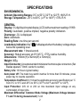
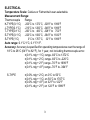
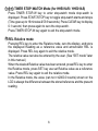
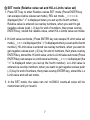
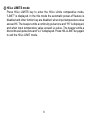
OMEGA
HH508/HH509/HH509R
Digital Thermometer
omega.com
TM
OMEGAnetSM On-Line Service
http://www.omega.com
USA: ISO 9001 Certified
One Omega Drive, Box 4047
Stamford, CT 06907-0047
Tel: (203) 359-1660
FAX: (203)359-7700
e-mail: [email protected]
Internet e-mail
[email protected]
Servicing North America:
Canada:
976 Bergar
Laval (Quebec) H7L5A1
Tel: (514) 856-6928
FAX: (514) 856-6886
e-mail: [email protected]
For immediate technical or application assistance:
USA and Canada:
Sales Service: 1-800-826-6342 / 1-800-TC-OMEGASM
Customer Service: 1-800-622-2378 / 1-800-622-BESTSM
Engineering Service: 1-800-872-9436 / 1-800-USA-WHENSM
TELEX: 996404 EASYLINK: 62968934 CABLE: OMEGA
Mexico and Latin America:
Tel: (95) 800-TC-OMEGASM
FAX: (95) 203-359-7807
En Español: (203) 359-7803
e-mail: [email protected]
Servicing Europe:
Benelux:
Postbus 8034, 1180 LA Amstelveen,
The Netherlands
Tel: (31) 20 6418405 FAX: (31) 20 6434643
Toll Free in Benelux: 06 0993344
e-mail: [email protected]
Germany/Austria:
Daimlerstrasse 26, D-75392
Deckenpfronn, Germany
Tel: 49 (07056) 3017 FAX: 49 (07056) 8540
Toll Free in Germany: 0800 82 66342
e-mail: [email protected]
Czech Republic:
ul. Rude armady 1868, 733 01 KarvinaHranice, Czech Repubic
Tel: 420 (69) 6311627 FAX: 420 (69) 6311114
e-mail: [email protected]
United Kingdom: ISO 9002 Certified
One Omega Drive
Riverbend Technology Centre Northbank, Irlam,
Manchester, M44 5EX, England
Tel: 44 (161) 777-6611 FAX: 44 (161) 777-6622
France:
9, rue Denis Papin, 78190 Trappes
Tel: (33) 130-621-400 FAX: (33)130-699-120
Toll Free in France: 0800-4-06342
e-mail: [email protected]
Toll Free in England: 0800-488-488
e-mail: [email protected]
It is the policy of OMEGA to comply with all worldwide safety and EMC/EMI regulations that apply. OMEGA is constantly pursuing certification
of its products to the European New Approach Directives. OMEGA will add the CE mark to every appropriate device upon certification.
The information contained in this document is believed to be correct but OMEGA Engineering, Inc. accepts no liability for any errors it contains,
and reserves the right to alter specifications without notice.
WARNING: These products are not designed for use in, and should not be used for, patient connected application.
INTRODUCTION
This instrument is a 3½ digit, compact-sized portable digital thermometer
designed to use external K/J/T/E/S type thermocouples as temperature
sensor. Temperature indication follows Reference Temperature/Voltage Tables
(N.I.S.T. Monograph 175 Revised to ITS-90) for K/J/T/E/S type thermocouples.
SAFETY INFORMATION
It is recommended that you read the safety and operation instructions before
using the thermometer.
WARNING
To avoid electrical shock, do not use this instrument when working
voltages at the measurement surface over 24V AC or DC.
WARNING
To avoid damage or burns, do not make temperature
measurement in microwave ovens.
CAUTION
Repeated sharp flexing can break the thermocouple leads. To prolong
lead life, avoid sharp bends in the leads, especially near the connector.
The
symbol on the instrument indicates that the operator must refer to an
explanation in this manual.
1
SPECIFICATIONS
ENVIRONMENTAL
Ambient Operating Ranges: 0°C to 50°C (32°F to 122°F) <80% R.H.
Storage Temperature: -20°C to 60°C (-4°F to 140°F) <70% R.H.
GENERAL
Display: 3½ digit liquid crystal display (LCD) with a maximum reading of 1999.
Polarity: Automatic, positive implied, negative polarity indication.
Overrange: -OL is displayed.
Zero: Automatic.
Reading Rate: one time per second.
" is displayed when the battery voltage drops
Low battery indication: the "
below the operating level.
Measurement rate: 1 times/second.
Accuracy: Stated accuracy at 23°C±5°C, <75% relative humidity.
Dimensions: 195mm(H) x 92mm(W) x 53mm(D).
Weight: 365g.
Input Connector: Accepts standard miniature thermocouple connectors (flat
blades spaced 7.9mm, center to center).
Battery Life: 100 hours typical battery.
Auto power off: The meter key switch inactive for more than 30 minutes, press
power key to resume operation.
Temperature Coefficient: 0.1 times the applicable accuracy specification per °C
from 0°C to 18°C and 28°C to 50°C (32°F to 64°F and 82°F to 122°F).
Input Protection: 24V dc or 24V ac rms maximum input voltage on any
combination of input pins.
Maximum Differential Common Mode Voltage (Maximum Voltage between
T1 and T2 during measurement): 1volt.
2
ELECTRICAL
Temperature Scale: Celsius or Fahrenheit user-selectable.
Measurement Range:
Thermocouple
Range
-200°C to 1372°C, -328°F to 1999°F
K-TYPE(0.1°C)
J-TYPE(0.1°C)
-210°C to 1200°C, -346°F to 1999°F
T-TYPE(0.1°C)
-200°C to 400°C, -328°F to 752°F
E-TYPE(0.1°C)
-220°C to 1000°C, -364°F to 1832°F
S-TYPE(1°C)
0°C to 1767°C, 32°F to 1999°F
Auto range: 0.1°C/1°C, 0.1°F/1°F.
Accuracy: Accuracy is specified for operating temperatures over the range of
18°C to 28°C (64°F to 82°F), for 1 year, not including thermocouple error.
±(0.1% rdg + 1°C) range -60°C to 1372°C
±(0.1% rdg + 2°C) range -60°C to -220°C
±(0.1% rdg + 2°F) range -76°F to 1999°F
±(0.1% rdg + 4°F) range -76°F to -364°F
S-TYPE
±(0.0% rdg + 2°C) on 0°C to 50°C
±(0.1% rdg + 1°C) on 50°C to 1767°C
±(0.0% rdg + 4°F) on 32°F to 122°F
±(0.1% rdg + 2°F) on 122°F to 1999°F
3
OPERATING INSTRUCTIONS
1
Power Switch
The
key turns the thermometer on or off. In the MIN MAX record mode
can not power off, must leave MIN MAX record mode then power off.
2 5 °C °F Selecting the Temperature Scale
Readings is displayed in either degrees Celsius(°C) or degrees
Fahrenheit(°F). When the thermometer is turned on, it is set to the
temperature scale that was in use when the thermometer was last turned
off. To change the temperature scale, press the °C or °F key.
3 " " Button
Press " " button to toggle on and off of backlight. The backlight will switchoff automatically after 30 seconds.
4 HOLD Mode
Pressing the HOLD key to enter the Data Hold mode, the "HOLD" annunciator is displayed. When HOLD mode is selected, the thermometer held
the present readings and stops all further measurements.
Pressing the HOLD key again to cancel HOLD mode causing thermometer
to resume taking measurements.
In the MIN/MAX recording mode, press HOLD key to stop the recording.
Press HOLD key again to resume recording. (Previously recorded reading
are not erased).
4
6 MIN MAX record Mode
Press MIN MAX key to enter the MIN MAX Recording mode, (displays the
Maximum reading, Minimum reading, "MAX-MIN" reading and Average
reading stored in record mode). In the this mode the automatic power-off
feature is disabled and key and all function key are disabled. The beeper
emits a tone when a new minimum or maximum value is recorded.
Push MIN MAX key to cycle through the MAX, MIN, MAX-MIN and AVG
readings.
If an overload is recorded, the averaging function is stopped and average
value display"-OL".
In the this mode, press HOLD key to stop the recording of readings, all
values are frozen, press again to restart recording.
To prevent accidental loss of MIN, MAX, "MAX-MIN" and AVG data, in this
mode can only be cancelled by pressing and hold down the MIN MAX key
for 2 seconds to exit and erased recorded readings.
WARNING
MIN, MAX and AVG readings can be recorded for a period of up to 50 hours
maximum. If this 50 hours period is exceeded the unit readings will not be
accurate.
7 8 9 T1 T2/T1-T2 (for HH501BR/HH501BS)
The input selection indicates which input is selected for display; T1
thermocouple, T2 thermocouple or the difference between the two thermocouples (T1-T2), when the thermometer is turned on, when the thermometer is turned on, it is set to the input selected that was in use when the
thermometer was last turned off.
5
7 8 9 TIMER STOP-WATCH Mode (for HH501AR / HH501AS)
Press TIMER STOP-W key to enter stop-watch mode stop-watch is
displayed. Press START/STOP key to toggle stop-watch starts and stops
(Time goes up to 19 minutes & 59.9 seconds). Press CLEAR key to display
0.1 second, then press again to zero the stop-watch.
Press TIMER STOP-W key again to exit the stop-watch mode.
10 REL Relative mode
Pressing REL key to enter the Relative mode, zero the display, and store
the displayed Reading as a reference value and annunciator REL is
displayed. Press REL key again to exit the relative mode.
The relative value can also be entered by the user. (See "SET mode" later
in this manual.)
When the desired Relative value has been entered, press REL key to enter
the Relative mode, press SET key use set Relative value as a reference
value. Press REL key again to exit the relative mode.
In the Relative mode, the value (can not >±2000.0 counts) shown on the
LCD is always the difference between the stored reference and the present
reading.
6
11 SET mode (Relative value set and Hi/Lo Limits value set)
1. Press SET key to enter Relative valuse SET mode (Press ENTER key
can escape relative valuse set mode), REL set mode. _ = = =.= is
displayed (the ".=" is displayed when you set up the fourth umber).
Relative value is entered via overlay numbers, when you want to get
negative values push (- 0) key for end of numbers, then press overlay
ENTER key, stored the relative value, enter Hi/Lo Limits value set mode.
2. Hi Limit value set mode, (Press ENTER key can escape Hi Limit value set
mode), _ = = =.= is displayed (the ".=" is displayed when you set up the fourth
number), Hi Limit value is entered via overlay numbers, when you want to
get negative values push (- 0) key for end of numbers, then press overlay
ENTER key, stored the Hi Limit value, enter Lo Limit value set mode (Press
ENTER key can escape Lo Limit value set mode), _ = = =.= is displayed (the
".=" is displayed when you set up the fourth number), Lo Limit value is
entered via overlay numbers, when you want to get negative values push
(- 0) key for end of numbers, then press overlay ENTER key, stored the Lo
Limit value and exit set mode.
3. In the SET mode, the value can not >±2000.0 counts.all value will be
memorized until yor reset it.
7
12 Hi/Lo LIMITS mode
Press Hi/Lo LIMITS key to enter the Hi/Lo Limits comparative mode,
"LIMIT" is displayed. In the this mode the automatic power-off feature is
disabled and other funtion key are disabled, when input temperature value
exceed Hi. The beeper emits a continuity pulse tone and "Hi" is displayed,
and when input temperature value exceed Lo value. The beeper emits a
discontinuous pulse tone and "Lo" is displayed. Press Hi/Lo LIMIT key again
to exit the Hi/Lo LIMIT mode.
8
OPERATOR MAINTENANCE
WARNING
To avoid possible electrical shock, disconnect the thermocouple
connectors from the thermometer before removing the cover.
Battery Replacement
Power is supplied by a 9 volt "transistor" battery. (NEDA 1604, IEC 6F22). The
" " appears on the LCD display when replacement is needed. To replace the
battery, remove the two screws from the back of the meter and lift off the
battery cover. Remove the battery from battery contacts.
9
RS-232 Operation Using Quick BASIC
The following example shows how to send command instruction and receive
data responses over the RS-232 interface using Quick BASIC.
The program example is set up on "COM1".
CLS
E$ = "A"
ST1:
CLOSE #1
OPEN "COM1:1200,E,7,1,DS,RS" FOR OUTPUT AS #1
PRINT #1, E$;
CLOSE #1
OPEN "COM1:1200,E,7,1,DS,RS" FOR RANDOM AS #1
ST2:
INPUT #1, A$
B$ = MID$(A$, 2, 6)
DEC = 0
F$ = "0123456789ABCDEF"
N=6
FOR I = 0 TO 5
C$ = MID$(B$, N, 1)
N=N-1
D = INSTR(F$, C$) - 1
DEC = DEC + (16 ^ I) * D
NEXT
DEC = DEC / 1000
C$ = MID$(A$, 1, 1)
10
IF C$ = "-" THEN
DEC = DEC * -1
END IF
B$ = MID$(A$, 10, 6)
DEC1 = 0
N=6
FOR I = 0 TO 5
C$ = MID$(B$, N, 1)
N=N-1
D = INSTR(F$, C$) - 1
DEC1 = DEC1 + (16 ^ I) * D
NEXT
DEC1 = DEC1 / 1000
C$ = MID$(A$, 9, 1)
IF C$ = "-" THEN
DEC1 = DEC1 * -1
END IF
CLS
LOCATE 12, 33
PRINT " T1
T2"
LOCATE 13, 30
PRINT USING "######.# ######.#"; DEC; DEC1
E$ = INKEY$
IF E$ = "" THEN
GOTO ST2
END IF
GOTO ST1
11
RS-232 Transmit and Receive Comammand Summary
1. Control letter should use Capital Letter.
Baud rate: 1200
Parity check: EVEN
Data bits: 7
Stop bits: 1
"A" Activate data transmission
"B" Stop data transmission
"C" °C/°F Key
"D" " " Key
"E" HOLD Key
"F" TYPE Key
"G" MIN/MAX Key
"H" Exit record mode
" I " T1 Key
"J" T2 Key
"K" T1-T2 Key
"L" REL Key
"M" Hi/Lo LIMITS Key
"P" Turn off power of meter
2. If you write you own program, the host computer must send the "A" letter to
activate data transmission.
3. If you should stop data transmission the host computer must send the "B"
letter to extend battery life.
4. Communication Parameters
12
OUTPUT DATA FORMATS
The data format consists of 32 bytes.
byte
0
0
0
0
0
0
0
0
0
1
1
1
1
1
1
1
1
1
1
2
2
2
2
2
2
2
2
2
2
3
3
3
1
2
3
4
5
6
7
8
9
0
1
2
3
4
5
6
7
8
9
0
1
2
3
4
5
6
7
8
9
0
1
2
S
H
H
H
H
H
H
A
S
H
H
H
H
H
H
A
D
D
D
D
D
D
A
A
A
A
A
A
A
A
CR
nl
T1 present status
T2 present status
Timer
S: Negative sign or positive sign
H: Hexadecimal digits
D: Numeric digits
A: Capital Letter or "-" sign
CR: Carriage return character
nl: newline character
01
T1 polarity
"+" Positive
09
T2 polarity
"-" Negative
0
1
2
02 — MSD
T1 Values=[H07x16 +H06x16 +H05x16
3
4
5
07 — LSD
+H04x16 +H03x16 +H02x16 ] / 1000
0
1
2
10 — MSD
T2 Values=[H15x16 +H14x16 +H13x16
3
4
5
15 — LSD
+H12x16 +H11x16 +H10x16 ] / 1000
08 — Thermocouple Type
"K" ® K type
"J" ® J type
"T" ® T type
"E" ® E type
"S" ® S type
13
Meter status
16
17
18
19
20
21
22
—
—
—
—
—
—
—
none
MSD
LSD
MSD
LSD
MSD
LSD
— "-"
(H)ours
(M)inutes
Time=INT[(Hx3600+Mx60+S)/2]
(S)econds
23 — Record mode
24 — REL & HOLD
mode
25 — none
26 — LIMITS mode
27 — Hi LIMITS
28 — Lo LIMITS
29 — none
30 — Battery status
"R"
"M"
"I"
"A"
"-"
"-"
"R"
"H"
"-"
"-"
"L"
"-"
"H"
"-"
"L"
"-"
"-"
"B"
"-"
®
®
®
®
®
®
®
®
®
Record mode
MAX mode
MIN mode
AVG mode
MAX-MIN mode
normal mode
Relative mode
HOLD mode
normal mode
®
®
®
®
®
®
Limits mode
normal mode
Hi Limits
normal mode
Lo Limits
normal mode
®
®
Low battery
normal mode
14
4612-IR232
RS232C CABLE
508BR
RS-232C "COM1" PORT
COMMUNICATION
1. Install the RSR232C cable between computer "COM1" and Thermometer
RS232C port.
2. Turn on Thermometer.
3. Utilize the Quick BASIC for inputting programs.
4. Use the capital control letter and input "A" letter from the keyboard to start
sending messages to computer.
5. Input "C" letter from the keyboard and then you can change the temperature
scale.
6. Input "F" letter from the keyboards and then you can circulating select the T1
input type.
7. Input "G" letter from the keyboard and then the meter enter record mode, and
then you can push "G" again to circulate through Maximum/Minimum/Average/
Record mode.
8. When you want to stop transmission mode you should push "B" letter from the
keyboard in order to conserve battery life.
15
HH501(A,B)K / HH501(A,B)J / HH501(A,B)T / HH501(A,B)E
HH508BR/HH508/HH509/HH509R
CALIBRATION PROCEDURE
Note: The following calibration procedure should perform only by qualified technicians
who have access to the items as following.
Equipment: The class of calibrator had better 10 times greater than the measured meter.
1. Set the jumper position on J1 position.
2. Input DCV 25.6mV to the T1 after the display is stabilized (forward 4 digits), then
press “ ENTER “ key and "01" is displayed.
3. Input DCV 74mV after the display is stabilized, then press “ENTER “ key and "OL"
is displayed.
4.
5.
6.
7.
Input 0°C (K-type) after the display is stabilized, then press “ENTER “ key.
Don't push any key and the meter will turn off automatically after 10 seconds.
After adjustment set the jumper back to J3 position.
Turn on the meter then input 0°C (K-type). The display reading reads 0°C if
the calibration procedure is right.
1
WARRANTY / DISCLAIMER
OMEGA ENGINEERING, INC. warrants this unit to be free of defects in materials and workmanship for a period of 13 months
from date of purchase. OMEGA Warranty adds an additional one (1) month grace period to the normal one (1) year product
warranty to cover handling and shipping time. This ensures that OMEGA's customers receive maximum coverage on each product.If
the unit should malfunction, it must be returned to the factory for evaluation. OMEGA's Customer Service Department will issue an
Authorized Return (AR) number immediately upon phone or written request. Upon examination by OMEGA, if the unit is found to
be defective it will be repaired or replaced at no charge. OMEGA's WARRANTY does not apply to defects resulting from any action
of the purchaser, including but not limited to mishandling, improper interfacing, operation outside of design limits, improper repair,
or unauthorized modification. This WARRANTY is VOID if the unit shows evidence of having been tampered with or shows evidence
of being damaged as a result of excessive corrosion; or current, heat moisture or vibration; improper specification; misapplication;
misuse or other operating conditions outside of OMEGA's control. Components which wear are not warranted, including but not
limited to contact points, fuses, and triacs.
OMEGA is pleased to offer suggestions on the use of its various products. However, OMEGA neither assumes responsibility
for any omissions or errors nor assumes liability for any damages that result from the use of its products in accordance
with information provided by OMEGA, either verbal or written. OMEGA warrants only that the parts manufactured by it
will be as specified and free of defects. OMEGA MAKES NO OTHER WARRANTIES OR REPRESENTATIONS OF ANY KIND
WHATSOEVER, EXPRESSED OR IMPLIED, EXCEPT THAT OF TITLE AND ALL IMPLIED WARRANTIES INCLUDING ANY
WARRANTY OF MERCHANTABILITY AND FITNESS FOR A PARTICULAR PURPOSE ARE HEREBY DISCLAIMED.
LIMITATION OF LIABILITY: The remedies of purchaser set forth herein are exclusive and the total liability of OMEGA with
respect to this order, whether based on contract, warranty, negligence, indemnification, strict liability or otherwise, shall
not exceed the purchase price of the component upon which liability is based. In no event shall OMEGA be liable for
consequential, incidental or special damages.
CONDITIONS: Equipment sold by OMEGA is not intended to be used, nor shall it be used: (1) as a "Basic Component" under 10
CFR 21 (NRC), used in or with any nuclear installation or activity; or (2) in medical applications or used on humans. Should any
Product(s) be used in or with any nuclear installation or activity, medical application, used on humans, or misused in any way,
OMEGA assumes no responsibility as set forth in our basic WARRANTY / DISCLAIMER language, and additionally, purchaser will
indemnify OMEGA and hold OMEGA harmless from any liability or damage whatsoever arising out of the use of the Product(s) in
such a manner.
RETURN REQUESTS / INQUIRIES
Direct all warranty and repair requests/inquiries to the OMEGA Customer Service Department. BEFORE RETURNING ANY
PRODUCT(S) TO OMEGA, PURCHASER MUST OBTAIN AN AUTHORIZED RETURN (AR) NUMBER FROM OMEGA'S
CUSTOMER SERVICE DEPARTMENT (IN ORDER TO AVOID PROCESSING DELAYS). The assigned AR number should then
be marked on the outside of the return package and on any correspondence.
The purchaser is responsible for shipping charges, freight, insurance and proper packaging to prevent breakage in transit.
FOR WARRANTY RETURNS, please have the following
information available BEFORE contacting OMEGA:
1. P.O. number under which the product was PURCHASED.
2. Model and serial number of the product under warranty, and
3. Repair instructions and/or specific problems relative to the
product.
FOR NON-WARRANTY REPAIRS, consult OMEGA for
current repair charges. Have the following information
available BEFORE contacting OMEGA:
1. P.O. number to cover the COST of the repair.
2. Model and serial number of product , and
3. Repair instructions and/or specific problems relative to the
product.
OMEGA's policy is to make running changes, not model changes, whenever an improvement is possible. This affords our customers the latest
in technology and engineering. OMEGA is a registered trademark of OMEGA ENGINEERING, INC. © Copyright 1999 OMEGA ENGINEERING,
INC. All rights reserved. This document may not be copied, photocopied, reproduced, translated, or reduced to any electronic medium or
machine-readable from, in whole or in part, without prior written consent of OMEGA ENGINEERING, INC.
Where Do I Find Everything I Need for
Process Measurement and Control?
OMEGA...Of Course!
TEMPERATURE
DATA ACQUISITION
þ Thermocouple, RTD & Thermistor
Probes, Connectors, Panels & Assemblies
þ Wire: Thermocouple, RTD & Thermistor
þ Calibrators & Ice Point References
þ Recorders, Controllers & Process Monitors
þ Infrared Pyrometers
þ Data Acquisition &
Engineering Software
þ Communications-Based
Acquisition Systems
þ Plug-in Cards for Apple, IBM
& Compatibles
þ Datalogging Systems
þ Recorders, Printers & Plotters
PRESSURE/STRAIN AND FORCE
þ
þ
þ
þ
Transducers & Strain Gauges
Load Cells & Pressure Gauges
Displacement Transducers
Instrumentation & Accessories
FLOW/LEVEL
þ Rotameters, Gas Mass Flowmeters
& Flow Computers
þ Air Velocity Indicators
þ Turbine/Paddlewheel Systems
þ Totalizers & Batch Controllers
pH/CONDUCTIVITY
þ pH Electrodes, Testers & Accessories
þ Benchtop/Laboratory Meters
þ Controllers, Calibrators, Simulators
& Pumps
þ Industrial pH & Conductivity Equipment
M-3203/0799
HEATERS
þ
þ
þ
þ
þ
Heating Cable
Cartridge & Strip Heaters
Immersion & Band Heaters
Flexible Heaters
Laboratory Heaters
ENVIRONMENTAL
MONITORING AND CONTROL
þ
þ
þ
þ
þ
Metering & Control Instrumentation
Refractometers
Pumps & Tubing
Air, Soil & Water Monitors
Industrial Water & Wastewater
Treatment
þ pH, Conductivity & Dissolved Oxygen
Instruments