1
DOC-6951/1.2
CrossFire 8600/8605
Token-Ring Switches
TM
Guide to Operations
TM
CrossFire 8600/8605
Token-Ring Switches
Guide to Operations
ii
Trademarks
GoCard and the Olicom clasped hands logo are registered trademarks of Olicom A/S. CellDriver,
ClearServer, ClearSession, ClearSight, CrossFire, LANscout, PowerMACH, RapidFire and RapidLAN
are trademarks of Olicom A/S. ClearCare, ClearPartner, ClearStep and ExpertWatch are service marks
of Olicom A/S. Olicom is a registered trademark. Other brand and product names are trademarks,
registered trademarks, service marks or registered service marks of their respective holders.
Copyrights
Olicom A/S reserves the right to modify the information given in this publication without prior notice.
The warranty terms and conditions applicable for your purchase of this equipment are given at the time
of purchase. Please consult your place of purchase for details.
Publication: DOC-6951 v. 1.2
Part Number: 710001641
© Copyright Olicom A/S, Denmark, November 1998
All rights reserved. No part of this publication may be reproduced, stored in a retrieval system, or
transmitted in any form or by any means, without the prior written permission of the publisher.
FCC Compliance
This equipment has been tested and found to comply with the limits for a Class A digital device, pursuant
to Part 15 of the FCC Rules. These limits are designed to provide reasonable protection against harmful
interference when the equipment is operated in a commercial environment. This equipment generates,
uses and can radiate radio frequency energy and, if not installed and used in accordance with the
instruction manual, may cause harmful interference to radio communications. Operation of this
equipment in a residential area is likely to cause harmful interference in which case the user will be
required to correct the interference at his own expense.
Warning: This is a Class A product. In a domestic environment this product may cause radio
interference in which case the user may be required to take adequate measures.
This device complies with part 15 of the FCC Rules. Operation is subject to the following two
conditions: (1) This device may not cause harmful interference, and (2) this device must accept any
interference received, including interference that may cause undesired operation.
Declaration of Conformity
We
Olicom A/S
CLASS 1 LASER PRODUCT
Nybrovej 114
DK-2800 Lyngby
Denmark
declare under our sole responsibility that the products
CrossFire 8600 Token-Ring Switch and/or CrossFire 8605 Token-Ring Fiber Switch
to which this declaration relates are in conformity with the following standards or other normative
documents
EN 50082-1
EN 55022
EN 60950 including Amendments
EN 60825-1
following the provisions of 89/336/EEC Directive and 73/23/EEC Directive.
CrossFire 8600/8605 Token-Ring Switches v. 1.2, P/N: 710001641
iii
Modifications
If the device is changed or modified without the express approval of Olicom A/S the user may void his
or her authority to operate the equipment.
Safety Notices
➽
➽
➽
➽
Danger: To avoid shock hazard, do not connect or disconnect any cables or perform installation,
maintenance, or reconfiguring of the CrossFire 8600 Token-Ring Switch and/or the CrossFire 8605
Token-Ring Fiber Switch during an electrical storm.
Danger: To avoid the possibility of electrical shock, switch power off and unplug the power cord from
the outlet before detaching the power cord from the CrossFire 8600 Token-Ring Switch and/or the
CrossFire 8605 Token-Ring Fiber Switch.
Danger: Do not open the CrossFire 8600 Token-Ring Switch and/or the CrossFire 8605 Token-Ring
Fiber Switch. Dangerous voltages inside.
Danger: To avoid shock hazard the power cord must be connected to a properly wired and earthed
receptacle. Any equipment to which the CrossFire 8600 Token-Ring Switch and/or the CrossFire 8605
Token-Ring Fiber Switch will be attached must also be connected to properly wired and earthed
receptacles.
Caution:
Observe the following power cable considerations before you begin installation of the CrossFire 8600
Token-Ring Switch and/or the CrossFire 8605 Token-Ring Fiber Switch.
➽
➽
1.
The socket outlet shall be installed near the equipment and shall be easily accessible.
2.
To prevent electrical shock, the power cord set used must comply with national regulations.
2a.
The female receptacle of the cord must meet CEE-22 requirements.
2b.
The cord must be UL listed, CSA labelled, and consist of three conductors with a maximum
of 15 feet in length.
Type SVT or SJT cord sets shall be used for units which stand on a desk or table. Type SJT
cord sets shall be used for units which stand on floor.
2c.
The male plug for units operating at 115 VAC shall consist of a parallel blade, grounding
type attachment plug rated 15 A, 125 VAC.
The male plug for units operating at 230 VAC shall consist of a tandem blade, grounding
type attachment plug rated 15 A, 250 VAC.
The male plug for units operating at 230 VAC (outside of the United States and Canada) shall
consist of a grounding type attachment plug rated 15 A, 250 VAC and have the appropriate
safety approvals for the country in which the equipment will be installed.
Caution: Support the CrossFire 8600 Token-Ring Switch and/or the CrossFire 8605 Token-Ring Fiber
Switch while you are installing the unit to avoid dropping it on the floor or any equipment beneath it in
the rack. The CrossFire 8600 Token-Ring Switch unit and the CrossFire 8605 Token-Ring Fiber Switch
unit each weighs approximately 8.8 kg (19.4 lbs).
Warning: All RJ45 connectors must only be connected to safety extra low voltage (SELV) circuits like
local area networking (LAN).
CrossFire 8600/8605 Token-Ring Switches v. 1.2, P/N: 710001641
iv
CrossFire 8600/8605 Token-Ring Switches v. 1.2, P/N: 710001641
v
Table of Contents
1. Overview and Specifications
Switching Technology . . . . . . . . . . . .
Switch of Switches . . . . . . . . . . . .
Switch of Servers. . . . . . . . . . . . .
Switch of Hubs . . . . . . . . . . . . . .
Switch of Desktops . . . . . . . . . . . .
Switch of Floors and Buildings . . . . . .
Switch of Routers. . . . . . . . . . . . .
Physical Characteristics . . . . . . . . . . .
Out-of-Band Management (OBM) . . . .
Token-Ring Ports. . . . . . . . . . . . .
Switched Port Analyzer. . . . . . . . . .
Universal Expansion Slots and Modules .
Reset Button . . . . . . . . . . . . . . .
System Request Button . . . . . . . . .
Labels . . . . . . . . . . . . . . . . . .
Status and Activity LEDs . . . . . . . . .
Features and Specifications . . . . . . . . .
Features . . . . . . . . . . . . . . . . .
Specifications. . . . . . . . . . . . . . .
1
.
.
.
.
.
.
.
.
.
.
.
.
.
.
.
.
.
.
.
.
.
.
.
.
.
.
.
.
.
.
.
.
.
.
.
.
.
.
.
.
.
.
.
.
.
.
.
.
.
.
.
.
.
.
.
.
.
.
.
.
.
.
.
.
.
.
.
.
.
.
.
.
.
.
.
.
.
.
.
.
.
.
.
.
.
.
.
.
.
.
.
.
.
.
.
.
.
.
.
.
.
.
.
.
.
.
.
.
.
.
.
.
.
.
.
.
.
.
.
.
.
.
.
.
.
.
.
.
.
.
.
.
.
.
.
.
.
.
.
.
.
.
.
.
.
.
.
.
.
.
.
.
.
.
.
.
.
.
.
.
.
.
.
.
.
.
.
.
.
.
.
.
.
.
.
.
.
.
.
.
.
.
.
.
.
.
.
.
.
.
2. Switch Theory of Operation
How the CrossFire 8600 and the CrossFire 8605 Works
Multiple Simultaneous Conversations . . . . . . . .
Low Latency . . . . . . . . . . . . . . . . . . . . .
Address Management . . . . . . . . . . . . . . . .
Multiple Bridging Modes . . . . . . . . . . . . . . .
Filtering . . . . . . . . . . . . . . . . . . . . . . . .
Congestion Control . . . . . . . . . . . . . . . . . .
Three Switching Modes . . . . . . . . . . . . . . .
Token-Ring Port Operation Modes . . . . . . . . . .
RI/RO-Like Connection. . . . . . . . . . . . . . . .
Transmission Priority Queues . . . . . . . . . . . .
CrossLink Connections. . . . . . . . . . . . . . . .
Spanning Tree Protocol Support . . . . . . . . . . .
VLAN Support . . . . . . . . . . . . . . . . . . . .
Management . . . . . . . . . . . . . . . . . . . . .
RMON Support . . . . . . . . . . . . . . . . . . . .
Built-in Port Counters. . . . . . . . . . . . . . . . .
Stackable Architecture . . . . . . . . . . . . . . . .
CrossFire 8600/8605 Token-Ring Switches v. 1.2, P/N: 710001641
. 2
. 2
. 3
. 3
. 3
. 4
. 4
. 5
. 5
. 6
. 6
. 7
. 7
. 7
. 7
. 8
10
10
12
17
.
.
.
.
.
.
.
.
.
.
.
.
.
.
.
.
.
.
.
.
.
.
.
.
.
.
.
.
.
.
.
.
.
.
.
.
.
.
.
.
.
.
.
.
.
.
.
.
.
.
.
.
.
.
.
.
.
.
.
.
.
.
.
.
.
.
.
.
.
.
.
.
17
18
19
19
20
22
23
23
24
24
25
25
25
26
27
28
29
30
vi
Optional Redundant Power Supply . . . . . . . . . . . . . . 30
Benefits of the CrossFire 8600 and the CrossFire 8605. . . . . . 32
3. Preparing for Installation
Safety Recommendations . . . . . . . . . . . .
Safety with Electricity . . . . . . . . . . . .
Preventing Electrostatic Discharge Damage
Site Requirements . . . . . . . . . . . . . . . .
Environment . . . . . . . . . . . . . . . . .
Chassis Accessibility . . . . . . . . . . . .
Cooling and Airflow . . . . . . . . . . . . .
Power . . . . . . . . . . . . . . . . . . . .
Unpacking and Inspecting . . . . . . . . . . . .
Rules to Remember . . . . . . . . . . . . . . .
Frame Length Limit . . . . . . . . . . . . .
Cables and Distances between Devices . .
Sample Applications for the CrossFire 8600 and
the CrossFire 8605 . . . . . . . . . . . . . . .
Important Management Considerations . . .
43
.
.
.
.
.
.
.
.
.
.
.
.
.
.
.
.
.
.
.
.
.
.
.
.
.
.
.
.
.
.
.
.
.
.
.
.
.
.
.
.
.
.
.
.
.
.
.
.
.
.
.
.
.
.
.
.
.
.
.
.
.
.
.
.
.
.
.
.
.
.
.
.
.
.
.
.
.
.
.
.
.
.
.
.
.
.
.
.
.
.
.
.
.
.
.
.
. 43
. 43
. 45
. 46
. 46
. 46
. 46
. 46
. 48
. 49
. 49
. 49
. . . . . . . . . 50
. . . . . . . . . 54
4. Installation
Required Network Preparation - Frame Length Limit
Installation Summary . . . . . . . . . . . . . . . .
Unpacking Instructions. . . . . . . . . . . . . . . .
Materials Needed for Installation . . . . . . . . . .
Installing a Universal Expansion Module . . . . . .
Mounting the Chassis . . . . . . . . . . . . . . . .
Rack or Cabinet Mounting . . . . . . . . . . . .
Table-Mounting . . . . . . . . . . . . . . . . .
Cabling. . . . . . . . . . . . . . . . . . . . . . . .
Connecting Devices to the Token-Ring Ports . .
Connecting Devices to the Token-Ring Ports
Using Building Wiring . . . . . . . . . . . . . .
Checking the Installation. . . . . . . . . . . . . . .
Applying Power . . . . . . . . . . . . . . . . . . .
Control Panels . . . . . . . . . . . . . . . . . . . .
Front Panel . . . . . . . . . . . . . . . . . . .
Back Panel. . . . . . . . . . . . . . . . . . . .
55
.
.
.
.
.
.
.
.
.
.
.
.
.
.
.
.
.
.
.
.
.
.
.
.
.
.
.
.
.
.
.
.
.
.
.
.
.
.
.
.
.
.
.
.
.
.
.
.
.
.
.
.
.
.
.
.
.
.
.
.
. 55
. 56
. 57
. 57
. 58
. 59
. 59
. 60
. 61
. 61
.
.
.
.
.
.
.
.
.
.
.
.
.
.
.
.
.
.
.
.
.
.
.
.
.
.
.
.
.
.
.
.
.
.
.
.
. 62
. 63
. 64
. 66
. 66
. 68
5. Connecting a Network Management Console
69
Connecting the Console . . . . . . . . . . . . . . . . . . . . . . 69
Communication Problems . . . . . . . . . . . . . . . . . . . 71
Diagnostic Screen . . . . . . . . . . . . . . . . . . . . . . . 72
CrossFire 8600/8605 Token-Ring Switches v. 1.2, P/N: 710001641
vii
6. Switch Configuration
General Guidelines . . . . . . . . . . . . . . . . . . .
Navigating within the Menus . . . . . . . . . . . .
Main Menu . . . . . . . . . . . . . . . . . . . . . . .
Configuration... . . . . . . . . . . . . . . . . . . .
Statistics... . . . . . . . . . . . . . . . . . . . . .
Download/Upload... . . . . . . . . . . . . . . . .
Reset... . . . . . . . . . . . . . . . . . . . . . . .
Exit Console . . . . . . . . . . . . . . . . . . . .
Configuration Menu . . . . . . . . . . . . . . . . . .
Switch Configuration Screen . . . . . . . . . . . . . .
Stack Configuration Screen . . . . . . . . . . . .
Module Information Screen. . . . . . . . . . . . .
VLAN Configuration . . . . . . . . . . . . . . . . . .
VLAN Configuration Menu . . . . . . . . . . . . .
VLAN Configuration Screen . . . . . . . . . . . .
VLAN Parameter Configuration for TrCRF Screen .
VLAN Parameter Configuration for TrBRF Screen .
Local VLAN Port Configuration Screen . . . . . .
IP Configuration Screen . . . . . . . . . . . . . . . .
BootP Requests and Parameters . . . . . . . . .
SNMP Configuration Menu . . . . . . . . . . . . . . .
Spanning Tree Protocol . . . . . . . . . . . . . . . .
IEEE 802.1D Spanning Tree Protocol (STP). . . .
Spanning Tree for TrBRF Screen . . . . . . . . .
Spanning Tree for TrCRF Screen . . . . . . . . .
Port Spanning Tree Parameters Screen . . . . . .
Current Spanning Tree Information Screen . . . .
Port Configuration Screen . . . . . . . . . . . . . . .
Switched Port Analyzer Menu . . . . . . . . . . . . .
CrossLink . . . . . . . . . . . . . . . . . . . . . . . .
CrossLink Menu . . . . . . . . . . . . . . . . . .
CrossLink Configuration Screen . . . . . . . . . .
Setting up a CrossLink . . . . . . . . . . . . . . .
Current CrossLink Information Screen . . . . . . .
Address Filtering . . . . . . . . . . . . . . . . . . . .
Filters and Port Security Menu . . . . . . . . . . .
Configure Filters Screen . . . . . . . . . . . . . .
Configure Port Security Mode Screen . . . . . . .
View Port Filters Screen . . . . . . . . . . . . . .
Protocol Filters Menu . . . . . . . . . . . . . . . .
Protocol Class Assignment Screen . . . . . . . .
Port Filtering Attributes Screen . . . . . . . . . . .
CrossFire 8600/8605 Token-Ring Switches v. 1.2, P/N: 710001641
75
.
.
.
.
.
.
.
.
.
.
.
.
.
.
.
.
.
.
.
.
.
.
.
.
.
.
.
.
.
.
.
.
.
.
.
.
.
.
.
.
.
.
.
.
.
.
.
.
.
.
.
.
.
.
.
.
.
.
.
.
.
.
.
.
.
.
.
.
.
.
.
.
.
.
.
.
.
.
.
.
.
.
.
.
.
.
.
.
.
.
.
.
.
.
.
.
.
.
.
.
.
.
.
.
.
.
.
.
.
.
.
.
.
.
.
.
.
.
.
.
.
.
.
.
.
.
.
.
.
.
.
.
.
.
.
.
.
.
.
.
.
.
.
.
.
.
.
.
.
.
.
.
.
.
.
.
.
.
.
.
.
.
.
.
.
.
.
.
. 76
. 77
. 78
. 78
. 78
. 78
. 78
. 78
. 79
. 81
. 84
. 85
. 87
. 88
. 89
. 90
. 92
. 93
. 94
. 96
. 97
. 97
. 98
. 99
. 101
. 103
. 104
. 105
. 109
. 109
. 111
. 112
. 113
. 114
. 115
. 116
. 117
. 119
. 120
. 121
. 122
. 123
viii
Address Aging . . . . . . . . . . . . . . . . . . .
Address Aging Menu . . . . . . . . . . . . .
Port Address Table Aging Screen . . . . . . .
Master Address Table Aging Screen . . . . .
Password Menu . . . . . . . . . . . . . . . . . .
Console/Telnet Sessions . . . . . . . . . . . . .
Console Configuration Menu . . . . . . . . .
Serial Link Configuration Screen . . . . . . .
Creating a Console Session Using a Modem .
Stopping the Console Session. . . . . . . . .
Telnet Configuration Screen . . . . . . . . . .
Telnet Sessions Screen . . . . . . . . . . . .
Starting the Telnet Session . . . . . . . . . .
Stopping the Telnet Session. . . . . . . . . .
Involuntary Termination of the Telnet Session
Download/Upload Menu . . . . . . . . . . . . . .
Serial Link Download Screen . . . . . . . . .
TFTP. . . . . . . . . . . . . . . . . . . . . .
TFTP Download/Upload Screen . . . . . . . .
Reset Screen . . . . . . . . . . . . . . . . . . .
.
.
.
.
.
.
.
.
.
.
.
.
.
.
.
.
.
.
.
.
.
.
.
.
.
.
.
.
.
.
.
.
.
.
.
.
.
.
.
.
.
.
.
.
.
.
.
.
.
.
.
.
.
.
.
.
.
.
.
.
.
.
.
.
.
.
.
.
.
.
.
.
.
.
.
.
.
.
.
.
.
.
.
.
.
.
.
.
.
.
.
.
.
.
.
.
.
.
.
.
.
.
.
.
.
.
.
.
.
.
.
.
.
.
.
.
.
.
.
.
.
.
.
.
.
.
.
.
.
.
.
.
.
.
.
.
.
.
.
.
Navigating Within the Menus . . . . . . . . . . . . . . . .
Statistics Menu. . . . . . . . . . . . . . . . . . . . . . . .
Switch Statistics Screen . . . . . . . . . . . . . . . . .
Port Status Screen. . . . . . . . . . . . . . . . . . . .
Port Statistics Menu . . . . . . . . . . . . . . . . . . .
General Statistics Screen . . . . . . . . . . . . . . . .
802.5 Statistics Screen . . . . . . . . . . . . . . . . .
802.5 State Information Screen . . . . . . . . . . . . .
802.5 DTR MAC Information Menu . . . . . . . . . . .
TXI Information Screen . . . . . . . . . . . . . . . . .
Station-CPort Information Screen . . . . . . . . . . . .
Address Tables Menu . . . . . . . . . . . . . . . . . .
Master Address Table Screen . . . . . . . . . . . . . .
Master Route Descriptor Table Screen . . . . . . . . .
VLAN Address Table screen . . . . . . . . . . . . . .
VLAN Route Descriptor Table Screen . . . . . . . . . .
Current Spanning Tree Information Screen . . . . . . .
Current Spanning Tree Information for a TrCRF Screen
VLAN Statistics . . . . . . . . . . . . . . . . . . . . .
VLAN Statistics Screen for TrCRF. . . . . . . . . . . .
VLAN Statistics Screen for TrBRF. . . . . . . . . . . .
.
.
.
.
.
.
.
.
.
.
.
.
.
.
.
.
.
.
.
.
.
.
.
.
.
.
.
.
.
.
.
.
.
.
.
.
.
.
.
.
.
.
7. Monitoring the Network with the Console
CrossFire 8600/8605 Token-Ring Switches v. 1.2, P/N: 710001641
125
126
127
128
129
130
130
131
132
132
133
134
135
135
135
137
138
139
139
142
145
146
147
148
150
152
153
156
159
160
161
163
165
166
168
170
171
172
175
178
178
179
ix
Diagnostic Test Results Screen . . . . . . . . . . . . . . . 180
Message Log Information Screen . . . . . . . . . . . . . . 181
Display Summary Screen . . . . . . . . . . . . . . . . . . 182
8. Monitoring the Network with SNMP
SNMP Setup . . . . . . . . . . . . . . . .
IP Configuration Screen . . . . . . . . . .
SNMP Configuration . . . . . . . . . . . .
SNMP Configuration Screen . . . . . .
Community Strings Screen . . . . . . .
Trap Receivers Screen . . . . . . . . .
List of Supported Traps from a Switch .
183
.
.
.
.
.
.
.
.
.
.
.
.
.
.
.
.
.
.
.
.
.
.
.
.
.
.
.
.
.
.
.
.
.
.
.
.
.
.
.
.
.
.
.
.
.
.
.
.
.
.
.
.
.
.
.
.
.
.
.
.
.
.
.
.
.
.
.
.
.
.
. 183
. 183
. 184
. 184
. 185
. 187
. 188
9. Monitoring Port Traffic
193
10. Troubleshooting
195
Obtaining Service . . . . . . . . . . .
Troubleshooting in a Network . . . . .
Start of Troubleshooting Process . . .
Choosing a Troubleshooting Procedure
.
.
.
.
.
.
.
.
.
.
.
.
.
.
.
.
.
.
.
.
.
.
.
.
.
.
.
.
.
.
.
.
.
.
.
.
.
.
.
.
11. Getting in Touch with Technical Support
Before You Contact Olicom Technical Support
Hotline Support . . . . . . . . . . . . . . . . .
Fax Support . . . . . . . . . . . . . . . . . .
Bulletin Board Service . . . . . . . . . . . . .
Standard Modem Requirements . . . . . .
ISDN Modem . . . . . . . . . . . . . . . .
Internet E-Mail . . . . . . . . . . . . . . . . .
Anonymous Internet FTP Server . . . . . . . .
Internet World Wide Web Server (WWW) . . .
Olicom Support WEB . . . . . . . . . . . . . .
Problem Report Form . . . . . . . . . . . . .
.
.
.
.
.
.
.
.
.
.
.
.
.
.
.
.
.
.
.
.
.
.
201
.
.
.
.
.
.
.
.
.
.
.
.
.
.
.
.
.
.
.
.
.
.
.
.
.
.
.
.
.
.
.
.
.
.
.
.
.
.
.
.
.
.
.
.
.
.
.
.
.
.
.
.
.
.
.
.
.
.
.
.
.
.
.
.
.
.
Appendix A. Abbreviations
Appendix B. Cable and Pin Information
Connecting to the Out-of-Band Management Port . . . . .
Out-of-Band Management Port and Cable Pin-Outs . . . .
Twisted-Pair Cable Pin Outs . . . . . . . . . . . . . . . .
Cabling Recommendations. . . . . . . . . . . . . . . . .
Cable Length and Lobe Wiring Rules for Dedicated-Media
LAN Segments . . . . . . . . . . . . . . . . . . . . . . .
CrossFire 8600/8605 Token-Ring Switches v. 1.2, P/N: 710001641
. 195
. 195
. 195
. 196
. 201
. 201
. 202
. 202
. 202
. 202
. 203
. 203
. 203
. 203
. 204
207
211
. 211
. 212
. 214
. 215
. 217
x
Cable Length and Lobe Wiring Rules for Shared-Media
LAN Segments. . . . . . . . . . . . . . . . . . . . . . . . 219
CrossFire 8600/8605 Token-Ring Switches v. 1.2, P/N: 710001641
xi
List of Figures
Figure 1. CrossFire 8600 Token-Ring Switch . . . . . . . . . . . .
Figure 2. CrossFire 8605 Token-Ring Fiber Switch . . . . . . . . .
Figure 3. Location of LEDs, Switches, and Connectors on
CrossFire 8600 . . . . . . . . . . . . . . . . . . . . . .
Figure 4. Location of LEDs, Switches, and Connectors on
CrossFire 8605 . . . . . . . . . . . . . . . . . . . . . .
Figure 5. Multiple Conversations Through a CrossFire 8600
or CrossFire 8605 Switch . . . . . . . . . . . . . . . . .
Figure 6. Typical Configuration with Switches Using
Multiple Bridging Modes . . . . . . . . . . . . . . . . . .
Figure 7. A Switch Configured with Two VLANs. . . . . . . . . . .
Figure 8. Typical LAN Segmentation . . . . . . . . . . . . . . . .
Figure 9. A Simple Application of the Switch . . . . . . . . . . . .
Figure 10. Typical Network without the CrossFire Switches . . . . .
Figure 11. Relieving the Overstressed Backbone. . . . . . . . . . .
Figure 12. Replacing SRBs with CrossFire 8600 or CrossFire 8605 .
Figure 13. Star-Wired Topology of Interconnected Switches . . . . .
Figure 14. Removing the Universal Expansion Slot Cover . . . . . .
Figure 15. Exposing the Rack Mounting Bracket . . . . . . . . . . .
Figure 16. Mounting the Switch in a Rack or Cabinet. . . . . . . . .
Figure 17. Connecting Devices to Token-Ring Ports . . . . . . . . .
Figure 18. Connecting using Building Wiring . . . . . . . . . . . . .
Figure 19. The Back Panel of the Switch . . . . . . . . . . . . . . .
Figure 20. View of Console Connection—the MANAGEMENT port .
Figure 21. Switch with four VLANs . . . . . . . . . . . . . . . . . .
Figure 22. Setting up CrossLinks . . . . . . . . . . . . . . . . . . .
Figure 23. TIA/EIA 232 Null-Modem Cable for the 25-pin Connector.
Figure 24. TIA/EIA 232 Null-Modem Cable for the 9-pin Connector .
Figure 25. Straight-Through Cable . . . . . . . . . . . . . . . . . .
Figure 26. Data Connector-to-RJ-45 Straight-Through Cable . . . .
CrossFire 8600/8605 Token-Ring Switches v. 1.2, P/N: 710001641
.
.
1
1
.
5
.
5
18
20
26
50
51
52
52
53
54
58
59
60
62
63
64
70
87
109
213
213
214
214
xii
List of Tables
Table 1.
Table 2.
Table 3.
Table 4.
Table 5.
Table 6.
Table 7.
Table 8.
Table 9.
Table 10.
Table 11.
Table 12.
Table 13.
Table 14.
Table 15.
Table 16.
Table 17.
Table 18.
Table 19.
Table 20.
Table 21.
Table 22.
Table 23.
Table 24.
Table 25.
Table 26.
Table 27.
Table 28.
Table 29.
Table 30.
Status LEDs and Their Meanings . . . . . . . . . . . . . .
Stack-link LEDs and Their Meanings . . . . . . . . . . . .
Port LEDs and Their Meanings . . . . . . . . . . . . . . .
Capacity Specifications . . . . . . . . . . . . . . . . . . .
Performance Specifications . . . . . . . . . . . . . . . . .
Specifications of Physical Characteristics . . . . . . . . .
Supported MIBs . . . . . . . . . . . . . . . . . . . . . . .
Token-Ring Port Operation Modes . . . . . . . . . . . . .
Switching Modes . . . . . . . . . . . . . . . . . . . . . .
Expansion Module Slots . . . . . . . . . . . . . . . . . .
Multiple Bridging Modes . . . . . . . . . . . . . . . . . .
Spanning Tree Protocol . . . . . . . . . . . . . . . . . . .
Management . . . . . . . . . . . . . . . . . . . . . . . .
Network Monitoring . . . . . . . . . . . . . . . . . . . . .
Filtering . . . . . . . . . . . . . . . . . . . . . . . . . . .
Connectivity Options . . . . . . . . . . . . . . . . . . . .
Front Panel Connectors and Push-Buttons . . . . . . . . .
Front Panel LEDs . . . . . . . . . . . . . . . . . . . . . .
Back Panel Switches and Connectors . . . . . . . . . . .
Console Configuration Settings . . . . . . . . . . . . . . .
Modem Settings. . . . . . . . . . . . . . . . . . . . . .
Changing and Saving Switched Port Analyzer Settings .
Symptom, LED State and Recommended Procedure . .
Connecting to the Management Port . . . . . . . . . . .
Pin-out of the Management Port . . . . . . . . . . . . .
Copper Cable Types . . . . . . . . . . . . . . . . . . .
Multimode Optical Fiber Cable Types. . . . . . . . . . .
Lobe Length for 150 Ohm Shielded Media . . . . . . . .
Lobe Lengths for 100 Ohm Shielded or Unshielded Cable
Lobe Lengths for 100 or 120 Ohm Shielded or
Unshielded Cable . . . . . . . . . . . . . . . . . . . . .
Table 31. Lobe Lengths for Recommended Fiber Cable . . . . . .
Table 32. Alternate Optical Fibers . . . . . . . . . . . . . . . . . .
CrossFire 8600/8605 Token-Ring Switches v. 1.2, P/N: 710001641
8
9
9
12
13
13
27
32
34
35
36
37
38
39
40
41
66
67
68
70
132
194
196
211
212
215
215
217
217
218
218
218
xiii
About this Manual
This manual is intended for network technicians familiar with the installation and
operation of networking equipment. It contains all the information required to
install and operate the CrossFire 8600 Token-Ring Switch and/or the CrossFire
8605 Token-Ring Fiber Switch.
TM
Unless one of the switches is mentioned alone, the information in this guide applies
to both CrossFire 8600 and CrossFire 8605.
The manual contains the following chapters and appendices.
Chapter 1, “Overview and Specifications”, is an overview of Token-Ring. It
explains how the switch is used in a Token-Ring. Included in the chapter is a list of
features and specifications.
Chapter 2, “Switch Theory of Operation”, explains how the switch improves
network performance.
Chapter 3, “Preparing for Installation”, deals with preparing for installation.
Chapter 4, “Installation”, contains instructions for installing, connecting and
verifying the operation of the switch.
Chapter 5, “Connecting a Network Management Console”, explains how to set
up a console connection for in-band or out-of-band switch management.
Chapter 6, “Switch Configuration”, deals with setting up and configuring the
switch using a direct console connection.
Chapter 7, “Monitoring the Network with the Console”, explains how to
monitor the switch using out-of-band management through a direct console
connection.
Chapter 8, “Monitoring the Network with SNMP”, explains how to monitor the
switch from a Network Management System using an application that supports
Simple Network Management Protocol.
Chapter 9, “Monitoring Port Traffic”, explains how to monitor ports on the
switch using SwitchProbe.
Chapter 10, “Troubleshooting”, gives troubleshooting hints that can be used to
locate and resolve minor problems.
Chapter 11, “Getting in Touch with Technical Support”, lists Olicom’s support
services such as hotline support, fax support and the support web, as well as other
services such as bulletin board service, FTP server and e-mail.
Appendix A, “Abbreviations”, lists the abbreviations used in this manual.
CrossFire 8600/8605 Token-Ring Switches v. 1.2, P/N: 710001641
xiv
Appendix B, “Cable and Pin Information”, lists cables and cable types that can
be used with CrossFire Token-Ring equipment.
❏
CrossFire 8600/8605 Token-Ring Switches v. 1.2, P/N: 710001641
1
1. Overview and Specifications
This chapter discusses switching technology and how the CrossFire 8600 TokenRing Switch and/or the CrossFire 8605 Token-Ring Fiber Switch can be used to
improve network performance. This chapter also includes a list of features and
specifications for the switch.
The topics of this chapter are presented under the following titles:
•
•
•
“Switching Technology”, starting on page 2.
“Physical Characteristics”, starting on page 5.
“Features and Specifications”, starting on page 10.
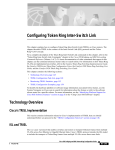
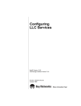
The figures below display a front view of the CrossFire 8600 Token-Ring Switch
and the CrossFire 8605 Token-Ring Fiber Switch.
Figure 1. CrossFire 8600 Token-Ring Switch
Figure 2. CrossFire 8605 Token-Ring Fiber Switch
CrossFire 8600/8605 Token-Ring Switches v. 1.2, P/N: 710001641
Overview and Specifications
2
Switching Technology
Demand for network bandwidth continues to grow, driven by the increasing
number of systems used in network-intensive applications. LAN segmentation has
been the prevalent method for addressing these demands and has been further
popularized by trends toward server centralization. However, the implementation
costs of LAN segmentation, as well as the real performance characteristics of
conventional network components, have served to limit growth of some TokenRing networks. Alternative technologies for addressing bandwidth demands
present yet other inhibitors, usually relating to costs. Token-Ring switching
provides users with an easy, cost-effective technique for addressing these demands.
Token-Ring switches, such as the CrossFire 8600 and the CrossFire 8605, increase
throughput between Token-Ring segments by supporting simultaneous, parallel
conversations. Switched connections between Token-Ring segments last only for
the duration of the packet—new connections can be made between different
segments for the next packet.
Token-Ring switches solve congestion problems caused by high-bandwidth
devices and powerful applications as well as the number of users. Therefore, each
of these devices—servers, for example—can be assigned its own 16 Mbps segment.
In Token-Ring networks, the major bottleneck is typically the throughput to highbandwidth devices such as servers, and between routers, bridges, and switches. An
effective solution is full-duplex communication, an option for each segment
connected to a CrossFire 8600 or a CrossFire 8605 port. Normally, Token-Ring
operates in half-duplex communication mode, which means stations can either
receive or transmit. With full-duplex technology, two communicating stations can
transmit and receive at the same time. When packets can flow in both directions
simultaneously, effective Token-Ring bandwidth doubles from 16 Mbps to 32 Mbps.
The CrossFire 8600 and the CrossFire 8605 can forward Token-Ring frames among
multiple, shared or dedicated Token-Ring LAN segments. Using a frame
forwarding technique similar to that of a multiport Token-Ring transparent bridge,
the switch uses Token-Ring MAC addresses to forward Token-Ring frames from
any of its ports to any other.
Switch of Switches
The CrossFire 8600 and the CrossFire 8605 can be deployed in a variety of network
configurations, all of which provide a significant increase in network performance.
The series of Olicom Token-Ring products allows users to build network systems
that can transport data efficiently and scale upwards as throughput requirements
increase. The switches deliver high-reliability and media flexibility. These features
combine to allow the switches to be used as a switch of switches which provides
media flexibility in an Token-Ring configuration.
CrossFire 8600/8605 Token-Ring Switches v. 1.2, P/N: 710001641
Overview and Specifications
3
The CrossFire 8600 and the CrossFire 8605 can easily connect with other CrossFire
products to deliver a broad range of network carrying capacity. Bandwidth is easily
scaled to meet all performance requirements.
Switch of Servers
With client/server applications, many client workstations may attempt to access a
single server at the same time. This traffic pattern may create bottlenecks at the
server. To further enhance performance, the CrossFire 8600 and the CrossFire 8605
can deliver dedicated bandwidth to high-speed file servers. All servers perform
better with dedicated 16 Mbps bandwidth.
Even better performance can be achieved by installing multiple adapters in the
server. By connecting these adapters to the switch, multiple 16 Mbps paths to the
server are created, a solution that is only possible when using a switch.
The switch ties together all Token-Ring devices lined to a local wiring center. In
networks, where a significant portion of the traffic moves locally between client
and server, the switch can be very effective.
Switch of Hubs
When network traffic increases beyond the capability of hubs, contention results.
Applications suffer and may even fail. The net effect of such a network
configuration is that all devices share a single 16 Mbps data path, thus reducing
overall network efficiency. The CrossFire 8600 and CrossFire 8605 can be very
effective when used as a switch of hubs.
The switches can alleviate contention through microsegmentation, or reducing the
number of devices in each shared segment. To provide microsegmentation, the
switches divides a single 16 Mbps segment into multiple 16 Mbps segments. As an
example, a workgroup has 16 Mbps of capacity. The 20 ports on the switches
support 10 simultaneous conversations with 20 hubs, thus providing the workgroup
with 160 Mbps bandwidth throughput, which results in a significant gain in
bandwidth.
Switch of Desktops
The CrossFire 8600 and the CrossFire 8605 are a cost-effective means of providing
dedicated bandwidth to individual desktop workstations. In this application, the
switch replaces a hub, providing excellent, hub-like network management
statistics. Total network capacity and throughput increase dramatically for attached
desktop workstations.
CrossFire 8600/8605 Token-Ring Switches v. 1.2, P/N: 710001641
Overview and Specifications
4
Switch of Floors and Buildings
For network managers, multistorey buildings and campuses can represent a unique
networking challenge. How can a network manager provide an efficient LAN
interconnect for users that are located on several floors of a building or in different
buildings?
Token-Ring switching and the CrossFire product family can provide the best
solution. The CrossFire 8600 and the CrossFire 8605 provide enhanced throughput
to local wiring closets that can be connected to a switch located in the data center.
Many networks consist of users located in different buildings of a campus
environment. The switches can be used as a collapsed backbone interconnecting
multiple buildings of a campus. They can provide the connectivity solution and
enhanced throughput that such campus environments require.
Switch of Routers
Router technology has had a significant impact on the design of today’s
internetworks. Routers have become the cornerstone of most production networks.
Although well equipped to provide firewall, WAN connectivity, security, and
connection between dissimilar LANs, routers are unable to provide high throughput
between desktop devices and servers. Because of these limitations, routers and
switches perform complimentary functions in the network.
The CrossFire 8600 and the CrossFire 8605 can be used as a front-end to routers to
increase performance in each subnet. Communication between local clients and
servers is enhanced at the workgroup level below the router.
The switches can also be used to back-end routers. In networks were many routers
are interconnected over Token-Ring and backbone performance is not acceptable,
the switches provide non-blocking communication between the routers for
enhanced network performance. This provides protocol transparency with
enhanced throughput in each subnet between local servers and desktops, thus
allowing network managers to build logical networks as large as network layer
protocol and broadcast traffic allow.
The SwitchProbe (Switched Port Analyzer) also gives a collapsed backbone
network superior network management and the ability to perform protocol analysis
from a single location. The SwitchProbe (Switch Port Analyzer) provides the latest
technology for monitoring switch-based networks and helps to reduce the cost of
managing these networks.
CrossFire 8600/8605 Token-Ring Switches v. 1.2, P/N: 710001641
Overview and Specifications
5
Physical Characteristics
STACK-LINK RX LED
STACK-LINK ATTACH LED
STACK-LINK TX LED
SysReq button
2 Expansion modules
CrossFire 8600
DIAG
STACK-LINK
ERR
MANAGEMENT
PWR DIAG ERR
RST
3
4
2
1
1
RX ATTACH
TX
TX
RX INS
TX
RX INS
TX
TOKEN-RING SWI
RX INS
TX
RX INS
DIAG
5
6
2
7
8
ERR
4
9
RST button (reset)
ERR LED
DIAG LED
PWR LED
MANAGEMENT port
(Out-of-Band
Management)
3
10
11
12
13
ACT
1
14
ACT
2
15
16
ACT
3
17
ACT
4
18
19
Port ACT LED
Port INS LED
20 Token-Ring UTP/STP ports
Figure 3. Location of LEDs, Switches, and Connectors on CrossFire 8600
STACK-LINK RX LED
STACK LINK ATTACH LED
STACK-LINK TX LED
SysReq button
2 Expansion modules
CrossFire 8605
DIAG
STACK-LINK
ERR
MANAGEMENT
1
INS
PWR DIAG ERR
RST
3
4
2
ACT
INS
1
RX ATTACH
TX
ACT
MANAGEMENT port
(Out-of-Band
Management)
INS
ACT
TX
RX INS
TX
RX INS
TX
TOKEN-RING SWI
RX INS
TX
RX INS
DIAG
INS
5
ACT
INS
6
ACT
INS
2
7
ACT
INS
3
8
ACT
RST button (reset)
ERR LED
DIAG LED
PWR LED
INS
9
ACT
INS
ERR
4
10
ACT
INS
11
ACT
INS
12
ACT
INS
13
ACT
INS
ACT
1
14
ACT
INS
15
ACT
INS
ACT
2
16
ACT
INS
ACT
3
17
ACT
INS
18
ACT
INS
ACT
4
19
ACT
INS
ACT
INS
Port ACT LED
Port INS LED
20 Token-Ring Fiber ports
Figure 4. Location of LEDs, Switches, and Connectors on CrossFire 8605
Out-of-Band Management (OBM)
The 9-pin, male, Out-of-Band Management (OBM) port labelled MANAGEMENT
functions as a DTE port.
This port enables attachment of a terminal, either local or remote, through a modem
connection. The terminal can be used to configure and monitor the switch.
The Out-of-Band Management port automatically detects the baud rate of the
terminal to which it is attached.
CrossFire 8600/8605 Token-Ring Switches v. 1.2, P/N: 710001641
Overview and Specifications
6
Token-Ring Ports
•
CrossFire 8600
Twenty shielded RJ-45 connectors for Token-Ring connection.
— Support for the IBM Cabling System via 150 ohm, shielded twisted-pair
(150 ohm STP); or 100 or 120 ohm unshielded twisted-pair via Category
3, 4, or 5 cables.
— These ports allow half-duplex (HDX) or full-duplex (FDX) connections to
other switches, hubs, or end nodes.
•
CrossFire 8605
Twenty fiber VF-45 connectors for Token-Ring connection.
— These ports allow half-duplex (HDX) or full-duplex (FDX) connections to
other switches, hubs, or end nodes.
•
The switch will automatically sense what type of Token-Ring connection is
being employed on each of its ports, whether it is a connection:
— to a shared-media segment via a Token-Ring concentrator (Station mode)
— to another Token-Ring switch
— operating at 4 Mbps or at 16 Mbps
— to a dedicated-media segment, directly to a Token-Ring LAN station
operating in half-duplex or full-duplex mode (Port mode)
The switch will automatically configure (requiring no operator action) each port to
operate at the highest level of capability possible. No special crossover cables are
required for Token-Ring stations on dedicated-media segments or for switch-toswitch connections; the same straight through cabling is used regardless of the type
of connection. This auto-sense/auto-configure capability of the switch can be
overridden by explicit console management.
Switched Port Analyzer
Any of the twenty Token-Ring ports can be configured as a TokenProbe port. It is
used to monitor any one of the other Token-Ring ports so that the activity can be
traced by a special passive network analyzer attached to the TokenProbe port.
CrossFire 8600/8605 Token-Ring Switches v. 1.2, P/N: 710001641
Overview and Specifications
7
Universal Expansion Slots and Modules
The switch contains two universal expansion slots (see Figure 3 or Figure 4) that
will accommodate optional, field-installable Universal Expansion Modules
(UEMs) that provide additional connections. Future UEMs will provide the
following types of connections:
•
•
•
•
•
•
OC-8610 4-Port Token-Ring UTP/STP
OC-8611 4-Port Token-Ring Fiber
OC-8320 ATM155 LANE Bridge UTP
OC-8321 ATM155 LANE Bridge MMF
OC-8650 High-Speed Token-Ring UTP
OC-8651 High-Speed Token-Ring MMF
Reset Button
The switch has a recessed reset button labelled RST that is located on the front
panel. Pressing the reset button resets the hardware and software and clears all
tables and memory, including the address tables. Pressing the reset button does not
clear those values stored in non-volatile random access memory (NVRAM).
System Request Button
This unlabelled recessed button is located on the front panel above the reset button.
Pressing the button causes the System Request menu to appear on the console
device attached to the MANAGEMENT port. Pressing the button for more than
five seconds will initiate a modem download of the main image.
➽
Note: The system request button should be used only at the direction of service
personnel. The button is recessed to prevent accidental activation.
Labels
The two labels in the right side of the front panel are:
•
The MAC Address Label:
The unique globally assigned base Base MAC-Address of the switch.
•
The Switch Number Label:
Blank label for an individual user identification of the switch.
CrossFire 8600/8605 Token-Ring Switches v. 1.2, P/N: 710001641
Overview and Specifications
8
Status and Activity LEDs
The switch features three status LEDs on the front panel that show the current status
of the switch. Also on the front panel are three LEDs that show activity for the
optional stacker link module. In addition, each Token-Ring port has two LEDs. On
CrossFire 8600, these two LEDs are unlabelled and located on the upper edge of
each port. On CrossFire 8605, these LEDs are located under each port and labelled
ACT and INS.
Refer to Figure 3 and Figure 4 in this chapter for the locations of all the LEDs.
Table 1 below lists the status LEDs and their meanings.
LED
PWR
DIAG
ERR
State
Meaning
Off
The switch is not connected to a power outlet, or
the power supply is faulty.
On
The switch is receiving power.
On
The DIAG diagnostics LED is on during the
power-on self-test.
Blinking
During download of a new software image, the
DIAG LED blinks to indicate the clearing (slow
blink) and loading (faster blink) of FLASH
memory.
On
The ERR LED is off during normal operation. If
the LED turns on, an error has occurred. Power
the switch down and up again. The ERR LED
should not turn on again. If it does, the switch is
faulty.
Note that the ERR LED also turns on if the switch
is powered only by an external power supply.
Table 1. Status LEDs and Their Meanings
The stack-link LEDs and port LEDs are described in the tables on the next page.
CrossFire 8600/8605 Token-Ring Switches v. 1.2, P/N: 710001641
Overview and Specifications
9
Table 2 lists the stack-link LEDs and their meanings.
LED
State
Meaning
TX
On or
blinking
Data is being transmitted to the stack link. It is
blinking, when the stack interface is inserted.
RX
On or
blinking
Data is being received from the stack link. It is
blinking, when the stack interface is inserted.
ATTACH
On
A connection has been established to the stack.
Table 2. Stack-link LEDs and Their Meanings
Table 3 lists the port LEDs and their meanings.
LED
INS
(left LED of
port)
ACT
(right LED of
port)
State
Meaning
On
The Token-Ring port is inserted into the ring.
Off
The Token-Ring port is not inserted into the ring.
Blinking
The Token-Ring port is disabled.
On or
blinking
Data is being transmitted to or received from the
port.
Table 3. Port LEDs and Their Meanings
CrossFire 8600/8605 Token-Ring Switches v. 1.2, P/N: 710001641
Overview and Specifications
10
Features and Specifications
Features and specifications for the CrossFire 8600 and the CrossFire 8605 are listed
below.
Features
Performance and Advanced Features
• Three switching modes:
— Low latency cut-through
— Store and Forward
— Auto (Adaptive cut-through)
•
Enhanced bridging modes:
— Transparent Bridging
— Source Route Switching
— Source Route Bridging (SRB)
— Source Route Transparent Bridging (SRT)
•
•
•
Support for duplicate MAC address schemes
Automatic port sensing of operating mode and media speed
Multiple Token-Ring port operation modes:
— Half-duplex concentrator and station
— Full-duplex concentrator and station (Dedicated Token-Ring)
— RI/RO-like connection
•
Spanning Tree Protocol support:
— IEEE 802.1D
— IBM Spanning Tree Protocol
•
CrossLink high-speed inter-switch connection
(up to 256 Mbps using eight ports)
•
•
•
•
Advanced filtering (MAC address / Protocol)
VLAN support
Support for transmission priorities
Congestion control
CrossFire 8600/8605 Token-Ring Switches v. 1.2, P/N: 710001641
Overview and Specifications
11
Management
• Extensive and sophisticated network management:
— SNMP management
— Out-of-band management via Telnet and VT100 consoles
— Graphical management application for HP OpenView for Windows 95 and
Windows NT (for information on additional management applications for
Unix, please contact your local Olicom sales representative)
•
•
•
•
•
•
Support for RMON and standard MIBs
Network statistics
LAN probe port mirroring
Fault isolation and detection
Download via TFTP or X-modem of new switch microcode
Up- and download of switch configuration via TFTP
Scalability and High Availability
• Up to 5,500 active LAN stations per group of four ports (1-4, 5-8, 9-12,
13-16, 17-20) with a maximum of 10,000 active LAN stations per switch
•
•
•
Stackable architecture
Optional redundant power supply
High density switch with seamless integration of LAN & ATM via LAN
emulation bridging
Installation
No special crossover cable required
•
•
•
Rack or surface mounting
Plug and Play for transparent forwarding:
— Automatic learning of network configuration
— Transparent to high-level protocol
•
•
Automatic sensing and configuration of ports
A factory-assigned MAC address (the switch can also be configured with a
locally administered MAC address)
CrossFire 8600/8605 Token-Ring Switches v. 1.2, P/N: 710001641
Overview and Specifications
12
Specifications
The tables on the following pages list the product specifications for the CrossFire
8600 and the CrossFire 8605.
Capacity
Specification
Value
Number of Token-Ring ports
(base configuration)
20
Maximum number of
additional Token-Ring ports in
expansion modules
8
Number of Token-Ring
switches in stack
8 using the CrossFire 8300 Switch Stacker
5 using the CrossFire 8635 Internal Stacker
Module
2 using the CrossFire 8630 Stacker Link
Module
Maximum number of TokenRing ports in stack
224 using the CrossFire 8300 Switch Stacker
140 using the CrossFire 8635 Internal Stacker
Module
56 using the CrossFire 8630 Stacker Link
Module
2 Expansion slots, choice of
4 x 4/16 Mbps RJ-45 Token-Ring
4 x 4/16 Mbps Fiber Token-Ring
1 x ATM155 Card (UTP and MMF)
2 x High-Speed Token-Ring (UTP and Fiber)
Global lookup table size
(stations and bridges)
10,000
Local lookup table size, total for 5,500
4 ports (stations and bridges)
Maximum number
of logical rings
63
Maximum number of VLANs
63
Table 4. Capacity Specifications
CrossFire 8600/8605 Token-Ring Switches v. 1.2, P/N: 710001641
Overview and Specifications
13
Performance
Specification
Maximum frame rate per port
Value
57,000 pps in each direction (measured with a
frame size of 19 bytes)
Maximum aggregate frame rate 200,000 pps in each direction. Full media
speed for frame sizes above 28 bytes
per 4 ports
Throughput per port
16 Mbps in each direction for all frame sizes
1,500,000 pps for smallest frame sizes
Aggregate switching rate
(unicast or broadcast) for entire
switch
Within switch latency
(cut-through)
35 µs
Table 5. Performance Specifications
Physical Characteristics
Specification
Value
Rack mount
19" rack mount (hardware included)
Dimensions
Width: 19" (48.3 cm)
Depth: 15.74" (40.0 cm)
Height 3.46" (8.80 cm)
Weight
19.4 lbs. (8.8 Kg)
Power
100 to 240 VAC autosensing
Frequency
50/60 Hz
AC current rating
1.5 A @ 120 V; 0.75 A @ 220 V
Thermal dissipation
(without modules)
CrossFire 8600: 90 W
CrossFire 8605: 80 W
MTBF
CrossFire 8600: 77,240 hours
CrossFire 8605: 40,342 hours
Table 6. Specifications of Physical Characteristics
CrossFire 8600/8605 Token-Ring Switches v. 1.2, P/N: 710001641
Overview and Specifications
14
Specification
Value
Operating Temperature:
Non-operating Temperature:
10 to 40°C (50 to 104°F)
-10 to 70°C (13 to 158°F)
Humidity:
Operating
Non-operating
8 to 80% (non-condensing)
90% @ 45°C (113°F)
Electromagnetic emissions
certification
FCC Class A
EN55022 Class A
VCCI Class A
Safety
UL1950
CSA C22.2 No. 950
EN60950
MANAGEMENT port
TIA/EIA-232-F, DB9 male connector
Software updates
Flash PROM, TFTP, X-modem
Protocol compatibility
Transparent to higher layer protocols
Spanning Tree Protocol
support
IEEE 802.1D compliant
IBM Spanning Tree
MIBs supported
SNMP MIB II (RFC1213)
SR Bridge MIB (RFC1525)
Bridge MIB (RFC1493)
Evolution of the Interfaces Group of MIB-II
(RFC1573)
RMON MIB/TR extensions - selected
groups only (RFC1757/1513)
IEEE 802.5 MIB (RFC1749/1748)
IEEE 802.5r DTR MIB
IEEE 802.5r DTR MAC MIB
oc8600 unit MIB
VTP MIB
Table 6. Specifications of Physical Characteristics
CrossFire 8600/8605 Token-Ring Switches v. 1.2, P/N: 710001641
Overview and Specifications
15
Specification
Network management
Value
-
SNMP Management Platform
-
Included in Olicom ClearSight
Management System
-
Additional management applications
available on Unix platforms:
—HP OpenView NNM for HP-UX
—Tivoli TME 10 NetView for AIX
Console
Telnet sessions
Switch Manager for HP OpenView for
Windows 95 and NT
Table 6. Specifications of Physical Characteristics
❏
CrossFire 8600/8605 Token-Ring Switches v. 1.2, P/N: 710001641
Overview and Specifications
16
CrossFire 8600/8605 Token-Ring Switches v. 1.2, P/N: 710001641
Overview and Specifications
17
2. Switch Theory of Operation
This chapter explains how the CrossFire 8600 Token-Ring Switch and/or the
CrossFire 8605 Token-Ring Fiber Switch improve network performance.
The topics of this chapter are presented under the following titles:
•
•
“How the CrossFire 8600 and the CrossFire 8605 Works”, starting on page 17.
“Benefits of the CrossFire 8600 and the CrossFire 8605”, starting on page 32.
How the CrossFire 8600 and the CrossFire 8605 Works
The CrossFire 8600 and the CrossFire 8605 are both IEEE 802.5-compliant devices
designed to boost throughput on Token-Ring networks. They operate as a Media
Access Control (MAC)-layer device that is protocol independent.
This chapter describes how the switch operates as a single stand-alone unit. The
switch contains the following main elements, as listed below:
•
Switching Bus—the architecture of the switch centers around the AXIS bus, a
520 Mbps switching fabric through which all switched ports communicate.
The AXIS bus is a partially asynchronous time division multiplexed bus used
for switching packets between heterogeneous LAN modules.
•
Token-Ring Ports—each port can attach to a classical Token-Ring segment or
to a dedicated station. Now users running basic applications are able to share
bandwidth, and users running bandwidth-intensive applications can receive
their own dedicated 16 Mbps port. Each dedicated port can also be set up in
full-duplex communication mode, so that each 16 Mbps port doubles to 32
Mbps.
•
Expansion Modules—each switch supports two expansion modules. These
modules include RJ-45 or fiber ports to provide up to eight additional 16 Mbps
ports, or high-speed connections such as 155 Mbps ATM, to provide two ATMRing connections for servers or backbone connectivity.
•
Stack Link Module—the switch supports a stack link module that can be used
to connect two switches from the CrossFire 8600 series in a back-to-back
configuration. Alternatively, up to five switches can be connected together
using and internal stacker module, and up to eight switches can be connected
together using the stack link module and an additional switch stack unit. By
connecting switches together through the stack link module, the switches
virtually combine to form a single unit, providing scalability, simplified
management, and enhanced performance.
CrossFire 8600/8605 Token-Ring Switches v. 1.2, P/N: 710001641
Switch Theory of Operation
18
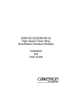
Multiple Simultaneous Conversations
A limitation of Token-Ring is that it supports only one packet at a time. The
CrossFire 8600 and the CrossFire 8605 improve data throughput by supporting
multiple, simultaneous, full-duplex conversations. By using High-Speed bus
switching technology, the switch creates multiple data paths. These switched
connections between Token-Ring segments last only for the duration of a byte
transmission. New connections are made “on-the-fly” between different ports on
the switch for the next byte.
Figure 5. Multiple Conversations Through a CrossFire 8600 or
CrossFire 8605 Switch
For example, as shown in Figure 5, while host A is transmitting a byte to host B,
the switch connects only the lines from A to B since there is no need to send packets
to all other ports. At the same time, a second switching circuit can connect host C
to host D. The result: Two packets are sent simultaneously.
➽
Note: The switch transmits broadcast and multicast packets on several switch ports
simultaneously.
The increase in throughput is directly proportional to the number of physical tokenrings that are interconnected through the switch. A switch with 20 ports
interconnected provides up to ten concurrent paths. With ten simultaneous
CrossFire 8600/8605 Token-Ring Switches v. 1.2, P/N: 710001641
Switch Theory of Operation
19
conversations, the switch creates 160 Mbps throughput in half-duplex mode, or 320
Mbps throughput in full-duplex mode.
A single segment can be dedicated to a single host or shared by several. To optimize
throughput, high-speed servers can be given dedicated switch ports.
By transporting multiple Token-Ring packets simultaneously, it boosts overall
network throughput.
Low Latency
When operating in cut-through mode, the switch minimizes latency—the time it
takes to forward a packet from one Token-Ring segment to another—by beginning
switching immediately after looking at the first six bytes of the destination address
in the packet. If the packet needs to be switched to another LAN segment, its data
begins flowing through the destination port before the entire packet has been
received. The result: packets can appear at the output port 35 microseconds after
entering the input port. Network devices that use store-and-forward technology
introduce much longer delays because they wait to receive the entire packet before
forwarding it.
By minimizing delay, the switch can move more packets freely throughout the
LAN without degrading performance.
Address Management
At power up, the system address tables do not contain any information. Whenever
a switch receives a packet with an unknown source or destination address, it learns
the new source address and stores its location in coming port in the address table.
If the destination address is unknown it sends the packet to all ports that can receive
data from the incoming port. When the response packet comes back, the switch will
learn the responder’s location and adds it to the address table. Once the address
table entries are created, the switch uses these learned address to switch all
subsequent packets to the port where the destination address is located.
The system address table maintains up to 10,000 entries, and each port address table
maintains 5,500 active Token-Ring addresses (each port address table is shared by
four ports, using the following: 1-4, 5-8, 9-12, 13-, etc.). If an address has not been
active for a configurable aging time, it is removed from the tables. This ensures that
the port’s address table is populated only by the most recently used address.
This capability allows users to transparently connect to high-volume backbone
networks.
CrossFire 8600/8605 Token-Ring Switches v. 1.2, P/N: 710001641
Switch Theory of Operation
20
Multiple Bridging Modes
The CrossFire 8600 and the CrossFire 8605 each supports four different switching
modes to provide maximum flexibility in all installation environments. The
switching modes are Source Route Switching (SRS), Source Route Bridging
(SRB), Source Route Transparent (SRT) and SRT/SRB. The switch operates on
two levels (BRF and CRF) as outlined below.
Figure 6. Typical Configuration with Switches Using Multiple Bridging Modes
The switch bridging modes are founded on the concept of Logical Rings. This
Logical Ring concept is equivalent to the DTR (IEEE 802.5r) standard’s
Concentrator Relay Function (CRF).
Each port on the switch belongs to a Logical Ring (CRF), which is a logical
grouping of ports within the switch. A Logical Ring can consist of any number of
ports within a switch or a switch stack. The ports within a Logical Ring do not have
to be adjacent.
The Logical Rings are assigned a ring number when the switch performs source
routing functions. The bridging is performed through the logical entity of the
Bridge Relay Function (BRF).
The Logical Ring (LR) communicates via a logical, virtual port with the Bridge
Relay Function, which functions as a multiport (virtual) bridge between the Logical
Rings. The switch can support up to 63 logical rings.
CrossFire 8600/8605 Token-Ring Switches v. 1.2, P/N: 710001641
Switch Theory of Operation
21
There are two levels of relay functions supported by the switch. The first level is
the TrCRF (Token Ring Concentrator Relay Function) to which the ports are
assigned. The second level is the TrBRF (Token Ring Bridge Relay Function). This
is the parent relay function to which TrCRFs are assigned. The switch maintains
certain configuration information and management statistics on a per BRF/CRF
basis. Therefore, when you access VLAN-specific switch configuration or
management screens (such as the Current Spanning Tree Information screen),
you will be prompted to specify the desired TrBRF for TrCRF.
Source Route Switching (SRS)
This mode is used between ports comprising a Logical Ring.
SRS switching combines the normal transparent bridge function with the ability to
forward frames based on source route information to locally attached source-route
bridges. The switch does not otherwise act as a source route bridge. For non sourcerouted packets, the switch decision is based upon destination MAC Addresses. For
source-routed packets, it is based on the source-route information combined with
the destination MAC address.
The switch learns MAC addresses and source-routing route descriptors of Source
Route Bridges attached to local switch ports.
Parallel paths are eliminated via the IEEE 802.1D Spanning Tree Protocol.
Source Route Bridging (SRB)
The BRF acts as a multiport Source Route Bridge between CRFs with the following
characteristics:
•
•
Each Logical Ring has a different ring number
•
•
Non-source-route frames are not forwarded between logical rings
Source Route Frames are forwarded between the Logical Rings by the Bridge
Relay Function based on the route information field
The Bridge Relay Function has a single bridge number and multiple ring
numbers (one per Logical Ring)
SRS is used between the ports of each logical ring. The Bridge Relay Function runs
the IBM Spanning Tree Protocol to eliminate parallel paths with other source-route
bridges. The IEEE 802.1D Spanning Tree Protocol is still used with each logical
ring. Duplicate MAC addresses are allowed only if they are on different Logical
Rings.
Source Route Transparent (SRT)
The BRF can combine transparent switching with Source Route Bridging. Non
source-routed packets are switched across logical rings by transparent bridging.
CrossFire 8600/8605 Token-Ring Switches v. 1.2, P/N: 710001641
Switch Theory of Operation
22
Source-routed frames are switched across logical rings by Source-Route Bridging
and within each logical ring by Source-Route Switching.
The Bridge Relay Function runs the IEEE 802.1D Spanning Tree Protocol.
Duplicate MAC addresses are not allowed.
SRT/SRB
This is a special mode combining SRT and the SRB switching modes. Each Logical
Ring will operate either in SRT mode or in SRB mode. Transparent bridging will
only take place between logical rings in SRT mode. Source-route bridging will take
place between all logical rings.
The purpose of the SRT/SRB mode is to allow duplicate MAC addresses to be used
when in SRT mode. The ports on which the duplicate MAC addresses reside can be
reached only by source routing.
The Bridge Relay Function runs the IBM Spanning Tree Protocol on the SRB
logical rings to eliminate parallel paths with all source route bridges. It runs IEEE
802.1D Spanning Tree Protocol on the SRT logical rings to eliminate parallel paths
with other SRT bridges. The two resulting spanning trees are joined together.
The IEEE 802.1D Spanning Tree Protocol is still used to eliminate parallel paths
within each logical ring whether it is SRB or SRT.
The benefit of the SRT/SRB mode is that it allows part of the network to be run in
SRT mode to accommodate applications that do not support source routing, while
still supporting duplicate MAC addresses on a number of SRB ports (for example,
for SNA gateway applications).
Filtering
Filtering is important for a LAN switch. Filters can be used to reduce broadcast
traffic, block certain protocols and provide security functions.
The switch provides filters for:
•
•
•
Destination or source MAC addresses
Destination service access point (DSAP)
Subnetwork Access Protocol (SNAP) type
Each protocol filter can be applied on a per-port basis for both input and output
traffic. This feature allows certain protocols to be blocked from certain ports. For
example, filters can be established to allow only Systems Network Architecture
(SNA) traffic to flow to ports with SNA gateways.
Source and destination MAC address filtering can be applied to all incoming
frames. The MAC address filters act in one of three ways:
CrossFire 8600/8605 Token-Ring Switches v. 1.2, P/N: 710001641
Switch Theory of Operation
23
•
Block destination address at a specific port—this prevents the specified port
from sending frames to a specified destination.
•
Allow destination address at specific ports—this indicates that the specified
port must send frames to the specified destinations only.
•
Force destination address to a specific port—this allows forwarding to a
unicast address that has not been learned. It can also be used to limit the
forwarding of Multicast addresses to a subset of ports. This last filter applies
to non-source-routing frames only.
Congestion Control
At regular intervals, the switch CPU inspects the queues on all output ports. If a
queue size is above a certain threshold, the port is instructed to:
•
•
Set the transmit priority for low priority frames to a specified high level
Delete old frames from the queue until it reaches a specified size
When the queue size again comes below a normal threshold size the port is
instructed to set the transmit priority back to the normal level.
Three Switching Modes
Cut-Through
In this mode the switch starts forwarding the packet to the output port as soon as
the destination address or the source-route of the incoming packet has been
resolved. This technique ensures very low latency, typically in the range of 30-100
µs. However, if errors occur on the input port during the reception of a packet, the
error will still be forwarded to the output port. Note that cut-through can only be
used in transmissions between ports which operate at 16 Mbps.
Store and Forward
In this mode, the switch receives the total packet from the input port, checks it for
any errors and then starts forwarding the packet to the destination port. This
technique will ensure that no faulty packets are transmitted by output port. The
negative impact however, is higher latency, typically in the range of 40–2,000 µs
depending on the packet size. Though slower than cut-through mode, this is still
much faster that conventional bridges.
Auto (Adaptive Cut-Through)
This is a technique whereby the switch will automatically swap between store-andforward and cut-through modes based on an error threshold. If the number of
received faulty packets is low, then cut-through mode is used; if the number of
CrossFire 8600/8605 Token-Ring Switches v. 1.2, P/N: 710001641
Switch Theory of Operation
24
faulty packets is high, the store and forward mode is used. This provides optimized
performance but introduces variable latency.
Token-Ring Port Operation Modes
Each Token-Ring port may operate in one of the following modes:
•
Half-duplex concentrator port
The port behaves like an active MAU port for classical Token-Ring. Connects
to a single station in half-duplex mode. This is also known as Token Passing
(TKP) port mode.
•
Half-duplex station emulation
The port is connected to a port on a MAU. Connects to a classical Token-Ring
segment with multiple stations. This is also known as Token Passing (TKP)
station mode.
•
Full-duplex concentrator port
Connects to a single station or to another switch in full-duplex mode. This is
also known as Transmit Immediate (TXI) port mode.
•
Full-duplex station emulation
Connects to another Token-Ring switch. This is also known as Transmit
Immediate (TXI) station mode.
•
RI/RO-like connection
The mode of operation can be configured manually or sensed automatically with
the exception of RI/RO, when equipment is connected to the port. The media speed
(4 or 16 Mbps) can also be manually configured or automatically sensed in all port
modes.
RI/RO-Like Connection
On CrossFire 8600, a RI/RO-like connection is available on fiber expansion ports
and on ports 19 and 20. On CrossFire 8605, a RI/RO-like connection is possible on
all the 20 fiber ports and on fiber expansion ports.
This feature allows the switch to connect to CAU/LAM systems using the RI/RO
connections thus providing a RI/RO-like functionality. This enables the switch to
be easily installed in existing Token-Ring networks.
A loop-back function has been implemented on these ports so that if the port is
disabled or the switch is powered off there will not be a break in the attached main
ring. This means that attaching a cable from the RI port of a MAU port to one of
the two switch ports in effect joins the primary and the backup ring in a MAU/CAU
main ring system. Connecting the other end of the RI/RO connection to the other
switch port, creates redundant paths because the two switch ports are connected to
CrossFire 8600/8605 Token-Ring Switches v. 1.2, P/N: 710001641
Switch Theory of Operation
25
the same segment. Therefore, the IEEE Spanning-Tree Protocol (STP) must be
enabled, which will place one port in forward and the other in blocked mode. If
there is a break in the main ring, the STP will place both ports in forward mode, and
all MACs on both segments will be relearned.
If a switch port has been configured to RI/RO mode, it will automatically sense
whether the port has been connected to RI or RO of the MAU.
➽
Note: It is not possible to automatically verify whether an UTP/STP port has been
connected according to the configuration. Any errors, such as attaching port 19 or
20 to a normal MAU port when the CrossFire 8600 port has been configured for
RI/RO, will cause a complete disruption of the ring to which the port is attached.
Therefore, be careful when using the RI/RO feature.
Transmission Priority Queues
To address the needs of delay-sensitive data, such as multimedia, the Token-Ring
ports of the switch have two transmit queues, a high-priority queue and a lowpriority queue.
The queue for a frame is determined by the value of the priority field in the frame
control (FC) byte. If FC priority is above a configurable level (default 3), the frame
is put into the high-priority queue. If an output port becomes congested, you can
dynamically configure the port to transmit all frames at high priority regardless of
the FC byte contents.
CrossLink Connections
Two switch stacks or switches may be interconnected by a number of parallel
Token-Ring connections (up to 256 Mbps using eight ports). The traffic between
the switches will be shared between the connections.
Spanning Tree Protocol Support
IBM initially supported only Source Route Bridging (SRB) in its bridges, so most
networks were built to use it. The main consideration for SRB implementations in
switches is the spanning-tree algorithm for spanning tree explorers (STEs). IBM
originally implemented a form of the Institute of Electrical and Electronics
Engineers (IEEE) spanning-tree algorithm. This algorithm, commonly referred to
as the IBM spanning tree, limits the STE frames to one copy per destination ring.
Some SRB implementations have also implemented the IEEE Spanning Tree
Protocol to be compatible with SRT bridges. The IEEE Spanning Tree Protocol is
not compatible with the IBM Spanning Tree Protocol.
The switch supports both the IEEE 802.1D and IBM Spanning Tree Protocols.
CrossFire 8600/8605 Token-Ring Switches v. 1.2, P/N: 710001641
Switch Theory of Operation
26
VLAN Support
The virtual LAN (VLAN) concept creates a virtual switch within a physical switch
or stack of switches. A VLAN consists of CRFs and has its own Bridge Relay
Function attached. Frames are not forwarded across VLANs and ring numbers must
be unique within a VLAN.
•
•
•
A VLAN consists of a number of ports of a switch or stack of switches
•
•
For each VLAN, the stack can be assigned a separate IP address
No frames are forwarded between ports belonging to different VLANs
Logical rings on different VLANs may be assigned the same ring number, but
ring numbers must be unique within the same VLAN
The spanning tree protocol is executed independently within each VLAN.
However, since all BRFs use the same Bridge ID for the spanning tree
algorithm, the spanning tree protocol will not function if ports from different
BRFs within one switch are connected.
A sample VLAN with a CrossFire 8600 or a CrossFire 8605 is shown below.
Figure 7. A Switch Configured with Two VLANs
CrossFire 8600/8605 Token-Ring Switches v. 1.2, P/N: 710001641
Switch Theory of Operation
27
Management
SNMP
The switch can be managed via a SNMP manager. It supports ten Management
Information Bases (MIBs). Six of the MIBs are standard MIBs, which are defined
by RFCs and are included with most SNMP management applications. Four of the
MIBs are proprietary and are provided on the disk that accompanies the switch.
SNMP management is supported via IP.
The following MIBs are supported:
Specification
MIB
RFC1213
MIB II
RFC1493
Bridge MIB
RFC1525
SR Bridge MIB
RFC1573
Evolution of the Interfaces
Group of MIB-II
RFC1757/1513
RMON MIB/TR extensions Only partial support
RFC1749/1748
IEEE 802.5 MIB
DTR MIB
IEEE 802.5r MIB
DTR MAC MIB
IEEE 802.5r MIB
Olicom
CrossFire 8600 switch series
Unit MIB
Olicom/Cisco
VTP MIB
Table 7. Supported MIBs
Most user configurable variables will be supported in either the standard MIBs or
the proprietary MIB. Configuration settings, such as port attributes, and operational
information, such as address tables, are fully accessible through SNMP. Certain
other settings, such as passwords and console settings, cannot be viewed or
modified via SNMP for security reasons.
CrossFire 8600/8605 Token-Ring Switches v. 1.2, P/N: 710001641
Switch Theory of Operation
28
Switch Manager for HP OpenView for Windows
The Switch Manager is an application that runs under HP OpenView for Windows.
It provides an intuitive graphical user interface (GUI) that displays a chassis
physical view and supports configuration, performance monitoring, and
troubleshooting.
This application is included with the switch.
For information about Switch Manager on other platforms, please contact your
local Olicom sales representative.
Telnet Management and VT100 Management (Console)
The Console Management function may be accessed out-of-band via the TIA/EIA232-F (i.e. RS-232) port labelled MANAGEMENT or in-band via Telnet.
IBM LAN Network Manager
The switch does not support management by the IBM LAN Network Manager, but
it will allow LAN Network Manager LLC frames to flow through the switch so that
communication to existing LNM manageable hubs and source route bridges will be
maintained.
Some error reporting functions and ring map functions might be lost for the rings
attached to through the switch, because a Token-Ring Switch will not (and should
not) forward MAC frames, but only LLC frames between ports.
RMON Support
RMON is an industry-standard method for providing network statistics monitoring
using SNMP. It also collects fault, performance, and configuration statistics. It can
monitor continuously, even when communication with the management station is
not possible or efficient. RMON can then notify the management station when an
exceptional condition occurs.
In typical SNMP management, the SNMP client has to continuously poll the switch
for fault, performance, and configuration information, waiting for the value to
change. This causes increased traffic through the network. With RMON, you can
have the switch monitor a particular statistic internally, and when the statistics
reaches a threshold, the switch will send a trap to the client. This monitoring
method reduces traffic between the SNMP client and the switch.
The following groups defined in the RFC 1757 RMON MIB are supported in the
switch:
CrossFire 8600/8605 Token-Ring Switches v. 1.2, P/N: 710001641
Switch Theory of Operation
29
•
The Statistics Group:
— The Token-Ring MAC-Layer Statistics Table.
— The Token-Ring Promiscuous Statistics Table.
•
The History Group:
— The History Control Table.
— The Token-Ring MAC-Layer History Table.
— The Token-Ring Promiscuous History Table.
The following groups defined in the RFC 1513 Token-Ring Extensions MIB are
supported in the switch:
•
The Token-Ring Ring Station Group:
— RingStationControl Table does not support sets, only gets.
— Ring Station Table is not supported.
•
The Token-Ring Ring Station Order Group.
You can use an external RMON probe for full RMON support.
➽
Note: Remember to enable RMON Statistics on the SNMP Configuration menu.
➽
Note: Access to RMON data is available only via an SNMP management
application that supports RFC 1757 and RFC 1513. You cannot access RMON via
the console interface of the switch.
Built-in Port Counters
The switch supports a wide range of port counters, which enables you to obtain a
detailed overview of the port traffic. The counters give a comprehensive overview
in the areas of:
•
•
•
MAC Layer Counters
MAC Layer Error Counters
Frame Forwarding Counters
CrossFire 8600/8605 Token-Ring Switches v. 1.2, P/N: 710001641
Switch Theory of Operation
30
Stackable Architecture
The CrossFire 8600 and the CrossFire 8605 switch can be stacked using the
CrossFire 8630 Stacker Link module, the CrossFire 8635 Internal Stacker module
or the CrossFire 8300 Switch Stacker for connecting up to eight switches in a stack.
Back-to-Back
Two CrossFire 8600 series switches can be connected together by fitting each
switch with the CrossFire 8630 Stacker Link module and connecting the switches
together using an appropriate stacker link cable. This simple connection doubles
the number of ports available, giving a total maximum of 56 ports.
Internal Stacker
The CrossFire 8635 Internal Stacker Module can be inserted into the stacker port of
a switch. It allows up to four additional switches from the CrossFire 8600 series to be
stacked together with the switch containing the CrossFire 8635. Each switch in the
stack must be equipped with a CrossFire 8630 Stacker Link module and an
appropriate stacker link cable. This can result in a stack of as many as five CrossFire
8600 series switches, supplying a total of up to 140 switched Token-Ring ports. The
CrossFire 8635 Internal Stacker Module works as a common backplane switching
fabric, which provides 1.4 Gbps of aggregate bandwidth.
External Stacker
The CrossFire 8300 Switch Stacker is an external stack unit that allows up to eight
CrossFire 8600 series switches to be stacked together. Each switch in the stack
must be equipped with an CrossFire 8630 Stacker Link Module and an appropriate
stacker link cable. This can result in a total of up to 224 switched Token-Ring ports.
The CrossFire 8300 Switch Stacker works as a common backplane switching
fabric, which provides 2.2 Gbps of aggregate bandwidth.
➽
Note: The CrossFire 8600 and the CrossFire 8605 can be stacked together with
switches from the CrossFire 8600 series in any desired combination. All switches
in a stack must, however, run the same software version.
Optional Redundant Power Supply
The switch has an input for a backup power supply. It is compatible with the
CrossFire 8310 Redundant Power Supply Chassis, which can supply backup power
for up to six switches, when up to six CrossFire 8311 Redundant Power Supply
Units are installed in the chassis. This gives a high degree of resilience to power
supply failures. The switch will start using the external power supply if the internal
supply fails. The switch monitors the power source and informs the network
management system which supply is in use.
CrossFire 8600/8605 Token-Ring Switches v. 1.2, P/N: 710001641
Switch Theory of Operation
31
The CrossFire 8300 Switch Stacker also accommodates an optional switch matrix
8301, which includes a redundant power supply, ensuring the highest degree of
resilience in the stack of switches.
➽
Caution: The redundant power supply unit CrossFire 8311 is not hot-swappable.
Both the CrossFire 8311 unit and the switch must be off before connecting or
disconnecting the DC power cable.
CrossFire 8600/8605 Token-Ring Switches v. 1.2, P/N: 710001641
Switch Theory of Operation
32
Benefits of the CrossFire 8600 and the CrossFire 8605
This section looks into the benefits that can be derived from the technical features
of the switch.
Token-Ring Port Operation Modes
Each port can be independently configured to one of the following operating
modes:
Feature
Function
Benefit
Half-duplex
concentrator port
Port behaves like an
active MAU port for
classical Token-Ring.
Connects to a single station in
half-duplex mode. Compatible
with older adapters.
Half-duplex station
emulation
The port is
connected to a port
on a MAU.
Connects to classical TokenRing segments with multiple
stations in existing
installations.
Full-duplex
concentrator port
Connects to a single
station in full-duplex.
Allows high-performance
station and server connection
and allows high performance
server attachments with up to
97% improvement over a halfduplex Token-Ring
connection.
Full-duplex station
emulation
Connects to another
switch in full-duplex
mode.
Allows easy connection
between switches.
RI/RO-like
connection
( CrossFire 8600 on
ports 19 and 20,
CrossFire 8605 on
all 20 fiber ports)
Allows connection
of the RI/RO port
from a MAU or CAU
directly to the
switch.
Enables easy integration into
existing installations.
Table 8. Token-Ring Port Operation Modes
CrossFire 8600/8605 Token-Ring Switches v. 1.2, P/N: 710001641
Switch Theory of Operation
33
Feature
Function
Benefit
Automatic port
sensing of operating
mode
The port senses
automatically which
mode to operate in.
Makes installation easier and
faster.
Automatic media
speed detection
(4 or 16 Mbps)
Enables the switch to
detect automatically
the speed of
individual ports.
Makes installation easier and
faster.
Congestion control
The size of each
port’s output queue
is monitored. In case
of congestion the
queue size is
adjusted through
frame priority
adjustment and
frame purging.
Minimizes the effect of
congestion on output ports
Table 8. Token-Ring Port Operation Modes
CrossFire 8600/8605 Token-Ring Switches v. 1.2, P/N: 710001641
Switch Theory of Operation
34
Three Switching Modes
Feature
Function
Benefit
Cut-Through
Switches with
minimum and
constant latency,
approximately 35 µs
Lowest possible switch-latency,
which means optimal response
time for end-users.
Store and Forward
Each packet is
forwarded only after
the entire packet has
been received by the
switch. This is used
for data transfer
between LAN
segments of different
speeds or for LAN
segments with a high
error rate.
Does not propagate errors to
other segments.
Auto
(Adaptive
Cut-Through)
Cut-through
switching that checks
for error packets. If a
port’s errors exceed a
user-defined threshold
then the port switches
to store and forward.
Same speed as cut-through
switching, but with built-in
adaptation to errors which
means that bandwidth is
effectively preserved
Table 9. Switching Modes
CrossFire 8600/8605 Token-Ring Switches v. 1.2, P/N: 710001641
Switch Theory of Operation
35
Expansion Module Slots
Feature
Function
Benefit
Four-port RJ-45
UTP/STP
Gives the switch an
additional 4 or 8
Token-Ring UTP/
STP ports.
Enables gradual expansion of
switch capacity.
Four-port fiber
(ST)
Gives the switch an
additional 4 or 8
Token-Ring Fiber
ports.
Enables installation in existing
fiber RI/RO connections and
fiber cabling environments (up
to 2 km).
ATM155 uplink
Gives the switch
access to 1 or 2
ATM155 uplink
connection(s) with
LAN Emulation.
Enables smooth migration to
ATM backbone networks and
enables redundant ATM
uplinks to be established.
Allows VLANs to be
multiplexed between switches
using ATM.
High-Speed TokenRing (HSTR)
Gives the switch
additional 2 or 4
HSTR ports.
HSTR allows Token-Ring
operation at 100 Mbps and
offers thus a 625 %
performance improvement
over “classic” 16 Mbps
Token-Ring.
HSTR is by far the most costeffective and non-disruptive
method for performance
upgrade of one existing
Token-Ring LAN.
Table 10. Expansion Module Slots
CrossFire 8600/8605 Token-Ring Switches v. 1.2, P/N: 710001641
Switch Theory of Operation
36
Multiple Bridging Modes
Feature
Function
Benefit
Transparent
and Source Route
Switching (SRS)
Switching is based on Allows easy installation in
MAC addresses only. environments with no need for
Source Route Bridging.
Learns MAC
addresses and source
routing route
descriptors of Source
Route Bridges
attached to local
switch ports.
Source Route
Bridging (SRB)
The switch ports may
be grouped into logical
rings. The switch acts
as a standard
multiport Source
Route Bridge between
logical rings. Non
Source Route frames
(NSR) are not
forwarded outside the
logical ring.
Allows easy installation in
existing Token-Ring networks
where Source Route Bridges are
used. Allows easy replacement
of bridges with switches.
Source Route
Transparent
Bridging (SRT)
NSR frames are
forwarded between
Logical Rings based
on MAC address.
Source Route frames
are forwarded as by
SRB.
Allows the mix of source route
and non source route protocols
in the network.
SRT/SRB
Combines the SRT
and SRB modes.
Allows the use of duplicate
MAC addresses when running in
SRT. Ports with duplicate MAC
addresses are reachable only via
source routing. Duplicate MAC
addresses are typically found in
installations utilizing SNA
gateways and/or front-ends.
Table 11. Multiple Bridging Modes
CrossFire 8600/8605 Token-Ring Switches v. 1.2, P/N: 710001641
Switch Theory of Operation
37
Spanning Tree Protocol
Feature
Function
Benefit
IEEE 802.1D
Allows redundant
network paths to be
defined in both SRB
and transparent
switching
configurations.
No single point of failure. The
duplicate STP modes allow
operation in both transparent
and source route bridging
modes
IBM
When in SRB/SRT
mode, a combination
of IBM spanning tree
and IEEE 802.1D is
used.
Same as above, and in addition
ensures compatibility in IBM
SRB installations.
Table 12. Spanning Tree Protocol
CrossFire 8600/8605 Token-Ring Switches v. 1.2, P/N: 710001641
Switch Theory of Operation
38
Management
Feature
Function
Benefit
SNMP
Can be configured
and managed using
SNMP management
station.
Allows integration into any
SNMP-based management
environment.
VLAN support
Ensures the
availability of a high
number of switched,
port based, VLANs
for an enterprise
network.
Eases network-wide
administration by enabling
ports to be grouped together in
a logical way. Provides
performance and security
control. Enables effective
broadcast control.
HP OpenView for
Windows
Additional Network
Management
applications available
for Unix platforms:
HP OpenView NNM
for HP- UX and
Tivoli TME 10
NetView for AIX
Full Graphical HP
OpenView for
Windows
management
application.
Allows full graphical
integration into HP OpenView
management environments.
Telnet management
Allows management
from a any LAN
station via Telnet.
Makes management flexible by
enabling management from
any station.
VT100
management
Allows out-of-band
management from an
external VT100 type
terminal connected
directly or via a
modem.
Enables management of
switches in remote locations.
Table 13. Management
CrossFire 8600/8605 Token-Ring Switches v. 1.2, P/N: 710001641
Switch Theory of Operation
39
Network Monitoring
Feature
Function
Benefit
RMON support
Support for TokenRing specific remote
monitoring.
Enables collection and analysis
of enhanced trafficmanagement data.
Passive Port
Monitoring
All traffic flowing on
the monitored port is
copied to the
monitoring port (the
monitoring port is a
true copy of the
monitored port).
Eases the management task by
making it easy to collect
Token-Ring statistics with a
special passive network
analyzer.
Active Port
Monitoring
All traffic switched
to and from the
monitored port is
also sent to the
monitoring port (the
order and timing of
frames on the
monitoring port can
be different).
Eases the management task by
making it easy to collect
network statistics and carry out
protocol analysis. Active
monitoring respects the MAC
protocol, allowing the use of a
standard network analyzer.
Built-in port
counters
Many MAC layer,
error, and frame
forwarding counters
are collected per port
Provides a detailed picture of
port traffic.
Table 14. Network Monitoring
CrossFire 8600/8605 Token-Ring Switches v. 1.2, P/N: 710001641
Switch Theory of Operation
40
Filtering
Feature
Function
Benefit
MAC address
Allows filtering
based on frame
source and
destination MAC
addresses.
Preserves available network
bandwidth by restricting traffic
from propagating beyond the
needed limits. Enables
enhanced network security
policies to be established.
Logical Link
Control (LLC):
DSAP/SNAP
Allows filtering
based on LLC
parameters DSAP
(Destination Source
Access Point) and
SNAP (Subnetwork
Access Protocol).
Same as above.
Table 15. Filtering
CrossFire 8600/8605 Token-Ring Switches v. 1.2, P/N: 710001641
Switch Theory of Operation
41
Connectivity Options
Feature
Function
Benefit
CrossLink highspeed inter-switch
connection (up to
256 Mbps using
eight ports)
Allows CrossFire
Token-Ring switches
to be interconnected
using 1-8 switch
ports.
Provides easy and scalable
switch inter connection.
Stackable:
3 possibilities:
A. 2 switch stack
B. 5 switch stack
C. 8 switch stack
Stack Products
Needing:
A. 2 x 8630
B. 1 x 8635 and
4 x 8630
C. 1 x 8300 and
8 x 8630
Allows several switches to be
stacked, accommodating
switch scalability up to 224
switched Token-Ring ports.
Optional
redundant power
supply
Up to six switches
can receive backup
power from one
CrossFire 8310
Redundant Power
supply, fully
equipped with six
CrossFire 8311
power supply units.
(Note that CrossFire
8311 is not hotswappable.)
Gives a high degree of
resilience to power supply
failures when used in critical
applications.
Table 16. Connectivity Options
❏
CrossFire 8600/8605 Token-Ring Switches v. 1.2, P/N: 710001641
Switch Theory of Operation
42
CrossFire 8600/8605 Token-Ring Switches v. 1.2, P/N: 710001641
Switch Theory of Operation
43
3. Preparing for Installation
Before installing the CrossFire 8600 Token-Ring Switch or the CrossFire 8605
Token-Ring Fiber Switch, read this chapter carefully.
The following topics are discussed in this chapter:
•
•
•
“Safety Recommendations”, starting on this page.
“Site Requirements”, starting on page 46.
“Unpacking and Inspecting” starting on page 48.
Safety Recommendations
Follow these guidelines to ensure general safety during and after the installation:
•
•
•
Keep the chassis area clear and dust-free during and after installation.
•
Wear safety glasses when working under any conditions that might be
hazardous to your eyes.
•
Do not perform any action that creates a potential hazard to people or makes
the equipment unsafe.
Keep tools away from walk areas where you and others could trip over them.
Do not wear loose clothing that could get caught in the chassis. Fasten your tie
or scarf and roll up your sleeves.
Safety with Electricity
Follow these guidelines when working on equipment powered by electricity.
➽
Danger: Do not open the switch. Dangerous voltages inside.
➽
Danger: To avoid shock hazard the power cord must be connected to a properly
wired and earthed receptacle. Any equipment to which the switch will be attached
must also be connected to properly wired and earthed receptacles.
➽
Warning: Before working on equipment that is connected to power lines, remove
jewelry (including rings, necklaces, bracelets and watches). Metal objects will heat
up when connected to power and ground and can cause serious burns or weld the
metal object to the terminals.
CrossFire 8600/8605 Token-Ring Switches v. 1.2, P/N: 710001641
Preparing for Installation
44
➽
Warning: Do not work on the system or connect or disconnect cables during
periods of lightning activity. Read the installation instructions before you connect
the system to its power source.
To turn power off the switch, you must disconnect the power cord; there is no
ON/OFF switch. Note that if the switch is connected to an external Redundant
Power Supply Unit (RPSU), the power cord must be removed from both units.
•
Locate the emergency power-off switch for the room in which you are
working. Then, if an electrical accident occurs, you can act quickly to turn off
the power.
•
Before working on the system, unplug the power cord. To avoid the possibility
of electrical shock, unplug the power cord from the outlet before detaching the
power cord from the switch.
•
Disconnect all power before doing the following:
— Installing or removing a chassis
— Working near power supplies
— Performing a hardware upgrade
•
•
•
Do not work alone if potentially hazardous conditions exist.
•
If an electrical accident occurs, proceed as follows:
Never assume that power is disconnected from a circuit. Always check.
Look carefully for possible hazards in your work area, such as moist floors,
ungrounded power extension cables, and missing safety grounds.
— Use caution; do not become a victim yourself.
— Unplug the power cord(s).
— If possible, send another person to get medical aid. Otherwise, assess the
condition of the victim and then call for help.
— Determine if the person needs rescue breathing or external cardiac
compressions; then take appropriate action.
CrossFire 8600/8605 Token-Ring Switches v. 1.2, P/N: 710001641
Preparing for Installation
45
Preventing Electrostatic Discharge Damage
Electrostatic discharge (ESD) can damage equipment and impair electrical
circuitry. It occurs when electronic components are improperly handled and can
result in complete or intermittent failures. Always follow ESD-prevention
procedures when removing and replacing components. Ensure that the chassis is
electrically connected to earth ground using an ESD mat or a ground wire. Wear an
ESD-preventive wrist strap, ensuring that it makes good skin contact. To safely
channel unwanted ESD voltages to ground, connect the clip to an unpainted surface
of the chassis frame. To properly guard against ESD damage and shocks, the wrist
strap and cord must operate effectively. If no wrist strap is available, ground
yourself by touching the metal part of the chassis.
➽
Caution: For safety, periodically check the resistance value of the antistatic strap,
which should be between 1 and 10 MΩ.
CrossFire 8600/8605 Token-Ring Switches v. 1.2, P/N: 710001641
Preparing for Installation
46
Site Requirements
Following are the site requirements for installation.
Environment
Choose a clean, dust-free, (preferably) air-conditioned location. Avoid direct
sunlight, heat sources, or areas with high levels of EMI (Electromagnetic
Interference).
Chassis Accessibility
Make sure the front and back panel of the equipment is accessible so that you can
monitor the LED indicators and access the control switches. Leaving enough
clearance at the front and back will also allow easier cabling and service.
Cooling and Airflow
Two fans, which are located at the left side of the switch, cool the interior by
drawing air through vents on the left side and forcing heated air out through holes
in the right side. If the internal temperature exceeds 50°C (112°F), a temperature
error is reported to the console.
➽
Caution: To protect the equipment from overheating, do not operate it in an area
that exceeds the maximum recommended ambient temperature of 40°C (104°F). To
prevent airflow restriction, you must allow at least 7.6 cm (3") of clearance around
chassis openings for proper airflow.
Power
The source electrical outlet should be installed near the switch, be easily accessible,
and be properly grounded.
Also, observe the following power cable considerations before you begin
installation of the CrossFire 8600 Token-Ring Switch and/or the CrossFire 8605
Token-Ring Fiber Switch.
1. The socket outlet shall be installed near the equipment and shall be easily
accessible.
2. To prevent electrical shock, the power cord set used must comply with national
regulations.
2a. The female receptacle of the cord must meet CEE-22 requirements.
CrossFire 8600/8605 Token-Ring Switches v. 1.2, P/N: 710001641
Preparing for Installation
47
2b. The cord must be UL listed, CSA labelled, and consist of three conductors
with a maximum of 15 feet in length. Type SVT or SJT cord sets shall be
used for units which stand on a desk or table. Type SJT cord sets shall be
used for units which stand on floor.
2c. The male plug for units operating at 115 VAC shall consist of a parallel
blade, grounding type attachment plug rated 15 A, 125 VAC.
The male plug for units operating at 230 VAC shall consist of a tandem
blade, grounding type attachment plug rated 15 A, 250 VAC.
The male plug for units operating at 230 VAC (outside of the United States
and Canada) shall consist of a grounding type attachment plug rated 15 A,
250 VAC and have the appropriate safety approvals for the country in which
the equipment will be installed.
➽
Caution: Support the CrossFire 8600 Token-Ring Switch and/or the CrossFire
8605 Token-Ring Fiber Switch while you are installing the unit to avoid dropping
it on the floor or any equipment beneath it in the rack. The CrossFire 8600 TokenRing Switch unit and the CrossFire 8605 Token-Ring Fiber Switch unit each
weighs approximately 8.8 kg (19.4 lbs).
➽
Caution: To separate the switch from the power, pull the power cord completely
out from the socket. The power socket must be easily accessible and located near
the unit.
➽
Warning: All RJ-45 connectors must only be connected to safety extra low voltage
(SELV) circuits like local area networking (LAN).
➽
Warning: This product relies on the building’s installation for short-circuit
(overcurrent) protection. Ensure that a fuse or circuit breaker no larger than
120 VAC, 15A U.S. (240 VAC, 10A international) is used on the phase conductors
(all current-carrying conductors).
➽
Warning: A voltage mismatch can cause equipment damage and may pose a fire
hazard. If the voltage indicated on the label is different from the power outlet
voltage, do not connect the chassis to that receptacle.
➽
Caution: If you are using the redundant power supply unit CrossFire 8311 note that
this unit is not hot-swappable. Both the CrossFire 8311 unit and the switch must
be off before connecting or disconnecting the DC power cable.
CrossFire 8600/8605 Token-Ring Switches v. 1.2, P/N: 710001641
Preparing for Installation
48
Unpacking and Inspecting
Immediately after receiving the equipment, examine all shipping containers and
contents for damage. If any damage has occurred, notify the shipping carrier.
Unpack the unit by removing the packing material and lifting it from its protective
enclosures. Visually examine the equipment and check the container for related
parts and accessories. You should have the following items:
•
One CrossFire 8600 Token-Ring Switch
OR
One CrossFire 8605 Token-Ring Fiber Switch
•
One CrossFire 8600/8605 Token-Ring Switches Guide to Operations
(this guide)
•
•
One OC-8830 Token-Ring Switch Program Disk Set
•
One CrossFire 8600 Series Token-Ring Switch Manager
for HP OpenView for Windows Guides to Operations
•
•
One serial cable for the management port
One OC-8840 Token-Ring Switch Manager for HP OpenView for Windows
(also works as stand-alone without HP Open View under Windows).
One plastic bag containing four adhesive rubber feet and rack mounting
screws, Allen key, nuts and washers.
Report any missing parts and any damage not related to shipping to your customer
service representative.
➽
Note: Keep the packing materials for future use. All components returned under
warranty should be shipped in their original packing materials.
If you have received your equipment before your site is fully prepared, after
inspection, you should keep all of the components in the original shipping
containers and store them in a physically and environmentally safe place.
When you are ready to begin the installation, please refer to the next chapter,
Chapter 4, “Installation”, for important instructions and directions.
CrossFire 8600/8605 Token-Ring Switches v. 1.2, P/N: 710001641
Preparing for Installation
49
Rules to Remember
This section will help you understand the physical configuration restrictions for the
switch. In brief, you must remember the following rules when planning to install
the switch:
•
•
18,192 byte maximum physical frame length.
•
•
Straight-through cables for all ports.
•
The spanning tree protocol will not function between different BRFs within
one switch.
For shared-media LAN segments, acceptable distances are defined by the hub
or concentrator attached to the switch port.
If you create parallel paths directly between switches, be sure that you have
enabled the spanning tree protcol (see “Spanning Tree for TrBRF Screen” on
page 99). The default setting for the spanning tree protocol is disabled.
The following paragraphs provide greater detail about the physical restrictions.
Frame Length Limit
The switch supports a maximum physical frame length of 18,192 bytes. This
corresponds to a Maximum Transfer Unit (MTU) of 17,800 bytes. The default
maximum physical frame length of the switch is 4,546 bytes which corresponds to
an MTU of 4,472 bytes.
Please read section “Required Network Preparation - Frame Length Limit” on
page 55 before you start the installation. This section contains more detailed
information on the frame length limits.
Cables and Distances between Devices
The CrossFire 8600 supports attachment to 100 ohm and 120 ohm twisted-pair
(UTP or STP), and 150 ohm STP, as defined in the EIA/TIA 568A and ISO/IEC
11801:1995.
On CrossFire 8605, a UTP/STP connection is only supported via the CrossFire
8610 Token-Ring UEM.
The CrossFire 8605 supports 50/125 µm and 62.5/125 µm fiber cables with a
VF-45 connector. Fiber cable lenghts up to 2000 meters are supported.
See Appendix B, “Cable and Pin Information” for specific information on
supported cable types, cable lengths and connector pinouts.
CrossFire 8600/8605 Token-Ring Switches v. 1.2, P/N: 710001641
Preparing for Installation
50
Sample Applications for the CrossFire 8600 and
the CrossFire 8605
The CrossFire 8600 and/or the CrossFire 8605 switch allows you to make
incremental changes in your network to address both immediate and long-range
performance challenges. For example, a Token-Ring LAN of 80 stations including
4 servers might experience performance problems as a result of increased traffic.
As it is currently structured, the LAN looks like the one in Figure 8.
MAU
Server
19 Workstations
MAU
Server
MAU
19 Workstations
Server
19 Workstations
Server
MAU
19 Workstations
Figure 8. Typical LAN Segmentation
All of the stations are attached to access units located in a single wiring closet. You
can install an switch in the same wiring closet and divide the LAN into 4 segments
of 20 stations each. One access-unit port from each segment will be connected to a
port on the switch via a patch cable. Finally, the four servers are removed from the
access units to which they have been attached and their cables moved to four ports
on the switch (as depicted in Figure 9).
Each group of 19 users attached to an access unit now shares a dedicated, 16 Mbps
path to the server. Each server has a dedicated, 16 Mbps path upon which to service
requests. The overall capacity of this solution is 64 Mbps; network capacity has
increased fourfold.
CrossFire 8600/8605 Token-Ring Switches v. 1.2, P/N: 710001641
Preparing for Installation
51
Servers
CrossFire 8600
MAU
CrossFire
OK
STACK-LINK
1
RX INS
TX
RX INS
TX
TOKEN-RING SWITCH OC-8600
RX INS
TX
TX
RX INS
MAU
OK
ERR
TX
MANAGEMENT
1
RX ATTACH
2
3
ERR
4
1
ACT
2
ACT
3
ACT
4
ACT
PWR DIAG ERR RST
2
3
4
5
6
7
8
9
10
11
12
13
14
15
16
19 Workstations
MAU
19 Workstations
17
18
19
20
19 Workstations
MAU
19 Workstations
Figure 9. A Simple Application of the Switch
Some large, multisegment, hierarchical Token-Ring networks experience
congestion at the campus backbone level. Although this congestion can often be
relieved by converting the backbone to a higher speed, shared-media protocol or by
installing additional bridges or dual backbones to eliminate bottlenecks, the
CrossFire 8600 switch and/or the CrossFire 8605 switch offer dedicated-media that
might be longer lived or more economical if you eventually need higher demand
applications.
Figure 10 on the next page illustrates a typical network without the CrossFire 8600
or the CrossFire 8605 switch. This network is a three-level, hierarchical, campus
network. Figure 11 and Figure 12 offer several alternatives for using
the CrossFire 8600 or the CrossFire 8605 switch.
CrossFire 8600/8605 Token-Ring Switches v. 1.2, P/N: 710001641
Preparing for Installation
52
Server
Server
5
SRB
SRB
Server
Server
4
6
SRB
SRB
SRB
SRB
SRB
SRB
1
2
3
7
8
9
Figure 10. Typical Network without the CrossFire Switches
In Figure 11, the congested campus backbone and the source-routing bridges
(SRBs) attached to it have been replaced by an CrossFire 8600 or a CrossFire 8605.
Figure 11. Relieving the Overstressed Backbone
CrossFire 8600/8605 Token-Ring Switches v. 1.2, P/N: 710001641
Preparing for Installation
53
The Next Step
Typically, the first point of congestion in this newly configured network would be
the servers. Because the usual mode of operation for a Token-Ring adapter is halfduplex, the servers can either send or receive information with one other segment
attached to the switch. If the server adapters are replaced with full-duplex adapters,
such as the Olicom OC-3118 or the Olicom OC-3137, and are attached as singlestation segments as shown in Figure 11, they can send and receive data
simultaneously. The capacity of each server is now 32 Mbps per port.
However, network congestion is not always at the backbone level. In Figure 12, the
two MAUs and six bridges have been replaced by a single switch. Internally, the
switch is configured with one BRF and seven CRFs, allowing the switch to replace
the MAUs and bridges without the need for further reconfiguration. This
configuration greatly improves performance by allowing switching directly from
ring to ring. The four servers, each with a full-duplex connection to the switch, have
been grouped in CRF 5.
If even better performance is needed, the switch shown in Figure 12 can be replaced
with a stack of switches. A stack can provide up to 224 ports, making it feasable to
connect workstations directly to a switch port. A direct connection provides a
dedicated 32 Mbps for users with high bandwidth requirements.
Switch
BRF
CRF 1
CRF 2
CRF 3
CRF 7
CRF 8
CRF 9
1
2
3
7
8
9
Server
CRF 5
32 Mbps
Server
Server
Server
Figure 12. Replacing SRBs with CrossFire 8600 or CrossFire 8605
CrossFire 8600/8605 Token-Ring Switches v. 1.2, P/N: 710001641
Preparing for Installation
54
Important Management Considerations
A star-wired topology (see Figure 13) helps determine problems in a network
because no single cable carries all of the traffic on the network. However, serial
connections could reduce network reliability since each connecting cable and
switch could potentially divide the network should a failure occur.
If you create parallel paths directly between switches, be sure you have enabled
spanning tree protocol (the default setting for spanning tree protocol is no or
disabled). Parallel paths create endless loops that cause unsatisfactory network
operation unless you configure the switch for spanning tree capability. The
spanning tree algorithm disconnects loops in networks using the transparent
bridging algorithm or the SRT algorithm, and will block a port of one of the
switches in the parallel paths. If the port in the primary path fails, the port that has
been blocked will change automatically to the forwarding state, keeping the
network operational.
CrossFire
OK
STACK-LINK
1
CrossFire
OK
STACK-LINK
1
PWR
2
1
RX ATTACH
DIAG
ERR
3
TX
RX
INS
TX
RX
INS
4
6
5
6
5
6
5
6
7
2
8
3
9
ERR
4
10
11
12
13
ACT
1
11
12
13
11
12
13
11
12
13
14
ERR
3
16
OK
1
4
2
8
3
9
TX
ERR
4
10
RX
INS
TX
ACT
1
14
RX
ERR
3
OK
1
4
INS
16
3
ERR
ERR
4
10
11
12
13
RX
1
14
INS
ACT
15
TX
RX
2
16
INS
TOKEN-RING SWITCH OC-8600
RX
TX
ACT
3
17
INS
ACT
18
TX
RX INS
4
19
ACT
20
CrossFire
RX INS
4
2
8
3
9
TX
ERR
4
10
RX
INS
TX
ACT
1
14
RX
RX
TX
INS
TX
ACT
3
INS
1
PWR
2
16
OK
1
2
8
3
9
TX
ERR
4
10
RX
1
14
INS
ACT
15
TX
RX
TX
INS
TX
ACT
3
17
RX
2
16
INS
2
3
ERR
4
RX
INS
4
5
6
5
6
5
6
5
6
7
8
9
10
11
12
13
11
12
13
11
12
13
11
12
13
14
1
PWR
2
OK
1
RX ATTACH
DIAG
ERR
3
4
7
2
8
3
9
TX
ERR
4
10
1
PWR
2
RX
INS
RX
TX
3
17
INS
ACT
18
TX
ERR
3
4
7
2
8
3
9
TX
ERR
4
10
1
PWR
2
RX
INS
TX
ACT
1
14
OK
1
RX ATTACH
DIAG
3
ERR
RX INS
4
ACT
INS
20
19
TOKEN-RING SWITCH OC-8600
RX
TX
INS
TX
ACT
3
17
RX INS
4
RX
INS
18
ACT
20
19
TOKEN-RING SWITCH OC-8600
RX
TX
ACT
2
15
16
INS
TX
ACT
3
17
RX INS
4
TX
RX
INS
TX
RX
INS
18
ACT
20
19
TOKEN-RING SWITCH OC-8600
RX
TX
INS
TX
RX INS
OK
ERR
TX
20
TX
18
RST
STACK-LINK
ACT
INS
ACT
3
ACT
16
CrossFire
RX INS
4
19
RX
2
15
TOKEN-RING SWITCH OC-8600
ACT
TX
ACT
1
14
OK
1
RX ATTACH
DIAG
RX
TX
OK
ERR
TX
20
TOKEN-RING SWITCH OC-8600
17
RST
STACK-LINK
ACT
19
INS
ACT
16
CrossFire
RX INS
4
18
RX
2
15
OK
ERR
TX
20
TX
ACT
1
RST
STACK-LINK
ACT
19
MANAGEMENT
7
ERR
3
CrossFire
RX INS
4
18
RST
4
1
RX ATTACH
DIAG
TX
OK
ERR
TX
20
TOKEN-RING SWITCH OC-8600
ACT
2
15
OK
STACK-LINK
ACT
19
OK
RX ATTACH
DIAG
3
9
TOKEN-RING SWITCH OC-8600
17
CrossFire
PWR
2
8
MANAGEMENT
7
ERR
1
TX
18
RST
STACK-LINK
TX
MANAGEMENT
7
OK
RX ATTACH
DIAG
INS
ACT
3
ACT
2
15
CrossFire
PWR
2
6
MANAGEMENT
7
ERR
1
RX
TX
17
RST
STACK-LINK
TX
MANAGEMENT
5
OK
RX ATTACH
DIAG
4
TOKEN-RING SWITCH OC-8600
ACT
2
15
CrossFire
PWR
2
2
RST
MANAGEMENT
5
ERR
1
ERR
3
RST
STACK-LINK
TX
MANAGEMENT
1
RX ATTACH
DIAG
OK
ERR
TX
MANAGEMENT
PWR
2
TX
OK
ERR
TX
MANAGEMENT
2
3
ERR
4
1
ACT
2
ACT
3
ACT
4
ACT
RST
4
7
8
9
10
14
15
16
17
18
19
20
Figure 13. Star-Wired Topology of Interconnected Switches
❏
CrossFire 8600/8605 Token-Ring Switches v. 1.2, P/N: 710001641
Preparing for Installation
55
4. Installation
This chapter contains step-by-step instructions for installing, connecting and
verifying that the CrossFire 8600 Token-Ring Switch and/or CrossFire 8605
Token-Ring Fiber Switch is operating properly.
Required Network Preparation - Frame Length Limit
The CrossFire 8600 and the CrossFire 8605 both support a maximum physical
frame length of 18,192 bytes (from the Frame Control (FC) to the Frame Check
Sequence (FCS) characters). This corresponds to a Maximum Transfer Unit (MTU)
of 17,800 bytes.
The default maximum physical frame length of the switch is 4,546 bytes which
corresponds to an MTU of 4,472 bytes. The actual MTU size of a VLAN is
configured in the VLAN Parameter Configuration for TrBRF screen, see
page 92.
The switch truncates frames larger than the configured maximum physical frame
length and adds an abort sequence at the end. Characteristically, if frames are sent
longer than the frame length limit, the abort sequences will be reported as frame
errors by other ring stations.
In a stack of switches, all stacker link modules in the stack must support 18,192
byte frames (18 KB frames) for any switch in the stack to support frames sizes
longer than 4,546 bytes. Additionally, if you are using ATM uplinks, all ATM
uplinks in the switch and in the stack must support 18 KB frames for any switch in
the stack to support frames sizes longer than 4,546 bytes.
To verify that your hardware supports 18 KB frames, view the Module
Information screen, described on page 85. Stacker link modules and ATM uplinks
that do not support 18 KB frames will have the text (4k) displayed immediately
after the hardware revision level.
For information on how to upgrade your stacker link modules or ATM uplinks that
currently do not support 18 KB frames, please contact your Olicom dealer or your
local Olicom representative.
➽
Note: It is most important that you consider the impact of the frame length limit,
and make sure that the workstations and servers in the network have been
configured to use a maximum frame length of equal or less than the switch. If this
is not done you may experience problems after the switch has been installed in the
network.
CrossFire 8600/8605 Token-Ring Switches v. 1.2, P/N: 710001641
Installation
56
Installation Summary
The installation sequence is listed in the steps below.
1. Plan for installation. Read Chapter 3, “Preparing for Installation”.
2. Unpack the switch.
3. Gather the materials.
4. If you will be installing expansion modules, install them now.
5. Mount the switch.
6. Connect the switch to the network.
7. Verify the operation of the switch.
➽
Note: Complete the following step only if you will be customizing the
configuration of the switch or monitoring its activity.
8. Configure the switch.
CrossFire 8600/8605 Token-Ring Switches v. 1.2, P/N: 710001641
Installation
57
Unpacking Instructions
There are no special safety precautions that need to be taken when unpacking the
switch. Simply follow these steps:
1. Open the large carton.
2. Remove the switch from its protective packaging.
3. Visually inspect the switch to ensure that it was not damaged during shipment.
4. Check the contents of the carton. Along with this manual, the carton should
contain:
•
One CrossFire 8600 Token-Ring Switch
OR
CrossFire 8605 Token-Ring Fiber Switch
•
One CrossFire 8600/8605 Token-Ring Switches Guide to Operations
(this guide)
•
•
•
One OC-8830 Token-Ring Switch Program Disk Set
•
One OC-8840 Token-Ring Switch Manager for HP OpenView for Windows
One CrossFire 8600 Series Token-Ring Switch Manager for HP OpenView for
Windows Guide to Operations (Olicom document number DOC-6960)
One plastic bag containing four adhesive rubber feet and rack mounting
screws, Allen key, nuts and washers.
If any item is missing or damaged, contact your place of purchase.
Materials Needed for Installation
To install the switch, you need the following items:
•
If the unit will be installed in a rack, you need:
— A rack inventory chart and a cabling chart from your network
administrator.
— The supplied set of screws, nuts and washers along with the Allen key tool.
— A properly earthed power cord.
•
If the unit will be installed on a surface (such as a tabletop), you will need:
— A cabling chart from your network administrator.
— The four supplied adhesive rubber feet.
— A properly earthed power cord.
CrossFire 8600/8605 Token-Ring Switches v. 1.2, P/N: 710001641
Installation
58
Installing a Universal Expansion Module
Follow these steps to install a Universal Expansion Module (UEM), if you have
received one.
1. If you have not already done so, unplug or remove power from the switch.
2. Remove the UEM from its box.
3. Remove the plate covering the Universal Expansion Slot (UES) on the front of
the switch by loosening the two thumbscrews holding it in place. See Figure 14.
Use a screwdriver if the screws are too tight to be removed with your fingers.
Retain the plate and thumbscrews for use in the event that the UEM is ever
removed.
4. Insert the card in the UES carefully, fitting each side into the card rails, and
making sure that the connector on the card is seated in the connector at the back
of the slot.
5. Secure the card with the two thumbscrews attached to it. This is illustrated in
the publication that was shipped with the UEM.
6. It may be necessary to download new microcode to the switch in order to use a
specific UEM. Refer to the instructions that came with your UEM package.
Figure 14. Removing the Universal Expansion Slot Cover
CrossFire 8600/8605 Token-Ring Switches v. 1.2, P/N: 710001641
Installation
59
Mounting the Chassis
The switch can be mounted in a standard 19-inch rack or cabinet, or can be mounted
on any flat surface such as a tabletop. The installation area should be near a power
source and should have enough room around the front and back panels for cabling
and access to controls. Use the following procedures for the installation of the
switch.
➽
Warning: Only trained and qualified personnel should be allowed to install or
replace this equipment.
Rack or Cabinet Mounting
If you install the equipment in a closed or multi-unit rack, observe the
environmental guidelines from the previous chapter, Chapter 3, “Preparing for
Installation”.
➽
Caution: The following rack mounting instructions need to be observed to ensure
that the switch and any other equipment are mechanically stable.
The following steps describe how to mount the switch in a rack or cabinet:
1. Remove the bracket covers on each side of the switch to expose the rack
mounting brackets. Access to the retaining screws is obtained by opening the
cap on the front of each bracket cover. Use the Allen key supplied with the
switch to remove the two 6 mm Allen screws. When you have removed the
screws, push the bracket cover towards the back of the switch and lift the cover
off. Keep the screws for later use.
Figure 15. Exposing the Rack Mounting Bracket
Before starting the next step, be sure you have the proper hardware for mounting
the chassis with the exposed brackets to your cabinet or rack.
CrossFire 8600/8605 Token-Ring Switches v. 1.2, P/N: 710001641
Installation
60
2. Position the switch, with the exposed mounting brackets, in the rack or cabinet
and slide it up or down until the bracket holes line up with the rack holes. Attach
the chassis brackets to the rack using the Allen screws you removed above and
the nuts supplied with the switch. Close the cap again to conceal the screws.
➽
Note: Only fixed brackets are supplied with these units. If you want to install a
sliding pullout mount, you will need to provide the extra mounting hardware.
Figure 16. Mounting the Switch in a Rack or Cabinet
Table-Mounting
The switch operates at a low noise level, which makes it suitable for a work area or
almost anywhere with a large enough flat surface such as a table, desktop, or similar
area.
Four self adhesive pads are supplied with the switch. The pads must be mounted in
the four recesses on the bottom of the switch. When the pads are mounted, simply
place the switch on a clear, level location. Leave enough room around the switch
for ventilation and access to the controls and cable connectors.
➽
Caution: Due to weight constraints, place no more than three units (or the
equivalent weight of other equipment) directly on top of another chassis. More than
three units on top of another unit may cause damage to the lower unit.
CrossFire 8600/8605 Token-Ring Switches v. 1.2, P/N: 710001641
Installation
61
Cabling
This section provides instructions for connecting devices (such as hubs, servers,
personal computers, and workstations) to the switch. Remember these tips when
connecting cables:
•
•
Avoid stretching or bending the cables excessively.
•
Avoid trip hazards by routing the cables away from aisles and other areas
where people walk. If such routes cannot be avoided, use floor cable covers or
similar material to secure and protect the cables.
•
Be sure that the cables connected to the switch are supported so that the cable
connectors are not excessively strained.
•
On CrossFire 8600, use a Category 3 or better UTP cable or a 150 ohm STP or
STP-A cable with an impedance-matching balun at each end.
•
On CrossFire 8605, the 20 fiber ports use VF-45 connectors. Note that these
are not compatible to the fiber ST Duplex connectors on the CrossFire 8611
TokenRing UEM. Standard converter cables are needed.
Avoid routing the cables near potential sources of electromagnetic
interference, such as motorized devices and fluorescent lights.
Connecting Devices to the Token-Ring Ports
If you will not be using building wiring (in-the-wall cables) to connect the device
to the switch, perform the following steps. If you will be using building wiring,
follow the steps beginning with step 1 on page 62.
Follow these steps to connect one or more devices to the Token-Ring ports on the
switch:
1. If you have a UEM, connect it using the instructions in the documentation
shipped with it and then return here.
2. Using the switch Cabling Chart provided by your network administrator as a
guide, connect the cables between the switch and other devices as illustrated in
Figure 17. Note that the figure illustrates an RJ-45 connector on each end.
Depending on the cable type you use, the device end of the cable may also have
a 9-pin D-shell or 150 ohm Data Connector.
3. If the switch is rack-mounted, dress the switch end of the cables through a cable
management bracket, if one is present on your rack.
4. Label each end of the cables so that it will be easy to find the device if you have
to troubleshoot a network problem.
Suggested information to place on the label includes the room location of the
CrossFire 8600/8605 Token-Ring Switches v. 1.2, P/N: 710001641
Installation
62
device at the other end, a unique cable identification number, the MAC address
of the connected device, and the number of the port to which the cable is
attached.
5. To continue installing the switch, go to “Applying Power” on page 64.
Figure 17. Connecting Devices to Token-Ring Ports
Connecting Devices to the Token-Ring Ports Using
Building Wiring
If you will use building wiring (in-the-wall cables) to connect the device to the
switch, perform the following steps:
1. If you have a UEM, connect it using the instructions in the documentation
shipped with it and then return here.
2. Using the Switch Cabling Chart provided by your administrator as a guide,
connect the cables between the devices and the faceplates as illustrated in
Figure 18.
3. Label the faceplate, so that it will be easier to find the device if you have to
troubleshoot a network problem.
4. In the wiring closet, connect a cable to the Token-Ring connector on the patch
panel or other equipment where the building wiring terminates.
➽
Note: On CrossFire 8600, do not connect these cables to the Ring-In or Ring-Out
port on a media access unit (MAU) unless you use port 19 or 20 on the switch.
5. Connect the other end of the cable to a Token-Ring port on the switch.
CrossFire 8600/8605 Token-Ring Switches v. 1.2, P/N: 710001641
Installation
63
6. Label this cable.
7. If the switch is rack-mounted, dress the switch end of the cables through a cable
management bracket, if one is present on your rack.
8. To continue installing the switch, continue with “Applying Power”.
Figure 18. Connecting using Building Wiring
Checking the Installation
Before you apply power to the switch, inspect the installation thoroughly. Verify
that all cables are installed correctly. Check cable routing, so a cable will not be
damaged or create a safety hazard. Be sure all equipment is mounted properly and
securely.
CrossFire 8600/8605 Token-Ring Switches v. 1.2, P/N: 710001641
Installation
64
Applying Power
The switch chassis does not have an on/off switch. Power is on when the unit is
plugged into a power source.
There are no user serviceable parts inside a switch. Any internal upgrades or service
should be performed by Qualified Personnel only.
➽
Warning: Unplug the power cord before you work on a system that does not have
an on/off switch.
➽
Warning: When installing the unit, the ground connection must always be made
first and disconnected last.
➽
Warning: This equipment is intended to be grounded. Ensure that the host is
connected to earth ground during normal use.
➽
Warning: Do not touch the power supply when the power cord is connected. Line
voltages are present within the power supply when the power cord is connected.
Use the following steps to power on your equipment.
1. Ensure that you are using the correct power source.
2. Using a power cable that complies with national regulations, plug the female
end of the cable into the AC power connector on the back panel of the switch
(see Figure 19).
3. Plug the male end of the power cord(s) into a properly grounded electrical
outlet.
Figure 19. The Back Panel of the Switch
CrossFire 8600/8605 Token-Ring Switches v. 1.2, P/N: 710001641
Installation
65
4. Verify that the power LED is on. If not, make sure the outlet is working properly.
If the outlet is working, but the power LED and the fans are not on, see Chapter
10, “Troubleshooting”.
5. When the switch powers on, observe the self-test diagnostic that the unit runs
for approximately 1-2 minutes. The DIAG LED is on for the duration of the test,
turning off when the self-test is complete.
6. At the completion of the diagnostics, the front panel LEDs should be
illuminated according to the status of the unit’s configuration. See the following
sections for a description of the controls and LEDs for the switch.
➽
Note: If the switch fails to power up correctly or if it encounters any unrecoverable
error, the ERR LED will be on or flashing on. If the ERR LED is on or flashes, see
Chapter 10, “Troubleshooting”.
➽
Caution: If you are using the CrossFire 8311 redundant power supply unit, note
that this unit is not hot-swappable. Both the CrossFire 8311 unit and the switch
must be off before connecting or disconnecting the DC power cable.
CrossFire 8600/8605 Token-Ring Switches v. 1.2, P/N: 710001641
Installation
66
Control Panels
The following tables list and describe the connectors, switches and status LEDs on
the switch.
Front Panel
Table 17 and Table 18 list the front panel controls on the switch.
Connectors and Push-Buttons
Name
Description
Ports 1 to 20
CrossFire 8600:
UTP/STP Token-Ring ports with RJ-45 jacks.
— Ports 19 and 20 can attach to a MAU/CAU RI/RO port.
CrossFire 8605:
Fiber Token-Ring ports using VF-45 connectors.
— All 20 fiber ports can attach to a MAU/CAU RI/RO port.
— On CrossFire 8605, UTP/STP connections are only
available via the CrossFire 8610 Token-Ring UEM.
MANAGEMENT
Console connection with DB-9 connector.
RST
Reset—full system reset of software and hardware.
SYS REQ
(unlabeled)
System Request—initiates a set of system request menus on
the attached console. If depressed for more than 5 seconds,
the switch will accept download of the main image from the
serial port via the X-modem protocol.
Table 17. Front Panel Connectors and Push-Buttons
CrossFire 8600/8605 Token-Ring Switches v. 1.2, P/N: 710001641
Installation
67
Status LEDs
LED
PWR
State
Meaning
Off
The switch is not connected to a power outlet, or
the power supply is faulty.
On
The switch is receiving power.
DIAG
On
The DIAG diagnostics LED is on during the
power-on self-test. During download of a new
software image, the DIAG LED blinks to indicate
the clearing (slow blink) and reloading (faster
blink) of FLASH memory.
ERR
On
The ERR LED is off during normal operation. If
the LED turns on, an error has occurred. Power the
switch down and up again. The ERR LED should
not turn on again.
Note that this LED turns on if the switch is
powered from a redundant power supply only.
TX
On or
blinking
Data is being transmitted to the stack link.
RX
On or
blinking
Data is being received from the stack link.
ATTACH
On
A connection has been established to the stack.
INS
(left LED of
port)
On
The Token-Ring port is inserted into the ring.
Blinking
The port is disabled.
ACT
(right LED of
port)
On or
blinking
Data is being transmitted to or received from the
port.
Table 18. Front Panel LEDs
CrossFire 8600/8605 Token-Ring Switches v. 1.2, P/N: 710001641
Installation
68
Back Panel
Table 19 lists the back panel connectors on the switch.
Name
Description
AC connection
Standard AC power connection.
Redundant power
supply
Connector for the optional redundant power supply unit.
Table 19. Back Panel Switches and Connectors
❏
CrossFire 8600/8605 Token-Ring Switches v. 1.2, P/N: 710001641
Installation
69
5. Connecting a Network Management
Console
Console interfacing can be established by connecting to the MANAGEMENT
serial port on the front panel of the CrossFire 8600 Token-Ring Switch and/or the
CrossFire 8605 Token-Ring Fiber Switch. Use this connection to set up in-band
management, which is the management of the switch through the network, or outof-band management, which is management outside of the network:
•
In-band management is a network management system that works through the
network:
— Olicom Switch Manager for HP OpenView for Windows
— Other Simple Network Management Protocol (SNMP) based applications
— Telnet sessions
•
Out-of-band management is a direct console connection to create a console
session for configuring and monitoring switches.
Network management applications (in-band management) are beyond the scope of
this guide. See the Olicom Switch Manager for HP OpenView—Guide to
Operations or the documentation supplied with you network management
application. How to connect the serial console (out-of-band management) for
configuring and monitoring the switch is described in this chapter.
Refer to the section “Console/Telnet Sessions” on page 130 for information on
configuring serial console and/or telnet console sessions.
Connecting the Console
The following steps explain connecting a serial terminal to the switch:
1. Connect the switch to a PC or other DTE (Data Terminal Equipment) device
using a straight, 25-pin to 9-pin TIA/EIA-232 cable (commonly known as a RS232 cable) and a null modem adapter or a 9-pin to 9-pin cable. See Appendix B
for a description of the cables and adapters.
2. Connect the TIA/EIA-232 cable to the DB-9 MANAGEMENT connector on
the front panel of the switch. This male DB-9 connector on the switch is
configured as a DTE device.
See Figure 20 to view the location of the cable connection on the front panel of the
switch.
CrossFire 8600/8605 Token-Ring Switches v. 1.2, P/N: 710001641
Connecting a Network Management Console
70
Figure 20. View of Console Connection—the MANAGEMENT port
The next step and table describe the settings to use for configuring a console in
order to communicate with the switch.
3. Use these values to set the configuration parameters on your console for
interfacing to the switch.
Specification
Value
Baud Rate
2400, 4800, 9600, 19200, 38400, 57600
Parity
None
Data bits
8
Stop bits
1
Handshaking
None
Terminal emulation
VT100
Duplex
Full
Software flow control
(XON/XOFF)
Off (input and output)
Hardware flow
control (RTS/CTS)
Off
Autobaud upon break
On
Line wrap
On
Table 20. Console Configuration Settings
CrossFire 8600/8605 Token-Ring Switches v. 1.2, P/N: 710001641
Connecting a Network Management Console
71
Specification
Value
Screen scroll
On
CR translation
CR
Backspace (BS)
translation
Destructive
Break length
(milliseconds)
350
Enquiry (ENQ)
Off
EGA/VGA true
underline
Off
Terminal width
80
ANSI 7 or 8 bit
commands
7
Microsoft Windows
™ terminal
emulation
Disable the Use Function, Arrow, and
Ctrl Keys for Windows option located in
the Terminal Preference menu
Table 20. Console Configuration Settings
4. At power on (cold boot), the switch performs a series of self-test diagnostics
verifying that hardware components are functioning. An example of the self-test
diagnostic screen is shown later in this chapter.
Communication Problems
If the diagnostic list does not appear, or is garbled, try adjusting the baud rates
between the console and the switch by using the Autobaud routine within the
switch. To do this, press the reset button on the front of the switch and wait for the
internal diagnostics to finish (the DIAG LED turns off). The reason for the reset is
that in case the switch’s Autobaud routine is not enabled, resetting it will set it to
its default mode of Autobaud enabled.
Depending on the type of console, there are several console command keys that will
potentially initiate the Autobaud routine in the switch. Four of those keys are
RETURN , the combination keys of ALT-B, the BREAK key, and ESC.
After the DIAG LED goes out, try one these command keys at the console, and
press it repeatedly. If there is no response, wait several seconds and again, press it
repeatedly. If necessary, perform the same routine using the other command keys.
CrossFire 8600/8605 Token-Ring Switches v. 1.2, P/N: 710001641
Connecting a Network Management Console
72
If that does not work, and there is at least a garbled output on the screen, try pushing
the unlabelled system request button on the switch. As soon as garbled characters
appear, press the console’s RETURN key twice in rapid succession. (Again, try the
other command keys as necessary).
If there is still a problem, try the following steps:
1. Check all of the cable connections.
2. Check the baud rate at the console’s set up screen; if it is not set to 9600, try that
setting.
3. Try setting the console baud rate to different values up or down, and pressing
RETURN for each selection.
4. If you are using a terminal emulation program, try exiting the program and
restarting.
5. If you still can not get the connection to work, contact technical support as
described in Chapter 11, “Getting in Touch with Technical Support”.
Diagnostic Screen
The diagnostic self-test displays two different screens (lists of information),
depending on whether you perform a cold boot (power on cycle with full
diagnostics), or a warm boot (a reset without full diagnostics).
During a cold boot, the following abbreviated list is an example of messages
(depending upon several factors, such as hardware, options, software version
levels) that appears on the console screen as the tests are performed. The warm boot
contains portions of the complete cold boot list.
The following is an example of a diagnostic screen during a boot process (the actual
screen may vary depending on such things as hardware, options, software version
levels and other factors):
BootStrap Firmware v2.3, Copyright 1996-1998
- Initiating bootstrapping sequence.
- Boot image integrity check...Passed.
- Control transferred to boot process.
Boot Firmware (Phase II) v2.3
- Program memory test........Passed.
- Relocating main image to
DRAM.......................................Done.
- Main image integrity check...succeeded.
- Control transferred to main process.
- Starting Power On Self Test Diagnostics.
CrossFire 8600/8605 Token-Ring Switches v. 1.2, P/N: 710001641
Connecting a Network Management Console
73
- Network memory test 32-bits........Passed.
- Network memory test 16-bits........Passed.
- Network memory test 8-bits........Passed.
- Port register and memory test.....................Passed.
- Single port loopback test.....................Passed.
- All ports linked loopback test.....................Passed.
- Port MAC test.....Passed.
- Completed Power On Self Test Diagnostics.
System Software Version 03.05, Copyright 1994-1998.
System started on Tue. November 10, 1998 14:30:03
8 Megabytes System memory
2 Megabytes Network memory
- Initialization started
- File system initialized
- System temperature is within safe operating levels
- Checking file system integrity
- Warmboot initialization started
- LAN ports detected:
- RJ-45 Token Ring: 1 2 3 4 5 6 7 8 9 10 11 12 13 14 15 16 17 18 19 20
- StkPort
: 29
- Initializing Ports: 1 2 3 4 5 6 7 8 9 10 11 12 13 14 15 16 17 18 19
20 29
- Initializing system address table
- System entering stand-alone mode
- System initialization complete
Starting SNMP v1/v2c bilingual agent task
Total MIB objects: 1236
- Enabling port: 1 2 3 4 5 6 7 8 9 10 11 12 13 14 15 16 17 18 19 20 29
Press RETURN key to activate console...
Depending upon which tests have run, verify that all diagnostics have passed and
that the ERR LED is off. If the ERR LED is on, read the screen to determine which
test failed. See also Chapter 10, “Troubleshooting”, to help find the cause.
At the end of the boot messages, you should be prompted to press RETURN. The
following greeting screen of the switch Console Manager should appear:
CrossFire 8600/8605 Token-Ring Switches v. 1.2, P/N: 710001641
Connecting a Network Management Console
74
At the top level screen, press the ENTER key (also called RETURN) to enter the main
menu. The contents of the main menu, the submenus and screens are described in
subsequent chapters. The information in these chapters includes configuring,
monitoring, and viewing statistics on the switch.
➽
Note: If you have forgotten the password, follow the description in the Note on
page 129.
❏
CrossFire 8600/8605 Token-Ring Switches v. 1.2, P/N: 710001641
Connecting a Network Management Console
75
6. Switch Configuration
This chapter explains how to set up the CrossFire 8600 Token-Ring Switch or the
CrossFire 8605 Token-Ring Fiber Switch and how to modify the configuration
using a VT100 console attached to the switch directly or via a modem connection.
The switch configuration can also be modified from a remote VT100 console via a
telnet session.
Subjects covered in this chapter:
•
•
•
•
•
•
•
•
•
•
•
•
•
•
•
•
General guidelines (page 76)
Main menu screen (page 78)
Configuration menu (page 79)
Switch and stack configuration (page 81)
Module Information (page 85)
Virtual LANs (page 87)
IP Configuration (page 94)
Spanning Tree Protocol (STP) (page 97)
Port Configuration (page 105)
CrossLink channels (page 109)
Address filtering (page 115)
Address aging (page 125)
Console Password (page 129)
Console/telnet sessions (page 130)
Download/Upload menu (page 137)
Reset menu (page 142)
CrossFire 8600/8605 Token-Ring Switches v. 1.2, P/N: 710001641
Switch Configuration
76
General Guidelines
To work within the console menus and screens, follow these guidelines:
•
To select an item on a screen or a menu, highlight it by using the arrow keys
and then press ENTER. If you need to specify additional information for that
item—for example, selecting Yes or No or supplying a value—a prompt
appears on the screen.
•
•
In most cases, new values are saved when you select Return.
•
•
•
Port refers to the number of a specific port on a switch.
The More item means there is more information than what is displayed on that
screen. Selecting More and pressing ENTER displays the next screen of
information.
Index refers to the numerical order of a list.
To return to the main menu from any screen, press CTRL-P. Note that any
changes made to the screen you were in will not be saved when you do this.
To return to the greeting screen, press CTRL-B.
•
•
To refresh the console screen, press CTRL-L.
•
•
•
The “VLAN” term in connection with CRF is discussed on page 26.
•
For protection against inadvertent or unauthorized access to configuration
screens, you may establish a password that users must enter at the greeting
screen. If no password is configured, just press ENTER and the main menu is
presented. To establish a password, see the section “Password Menu,” later in
this chapter. To open the Password menu, select Configuration... in the main
menu and then select Password... in the Configuration menu. For more
explanation on the greeting screen, see Chapter 5, “Connecting a Network
Management Console”.
If you are administering switches in a stack, many of the console screens will
prompt for a box number. Enter the number of the box you want to administer.
The terms “Virtual LAN” and “domain” are interchangeable.
The console automatically returns to the greeting screen after five minutes of
inactivity. Five minutes is the default value. The time can be changed at the
Console Configuration menu as explained later in this chapter. To open the
Console Configuration menu, select Configuration... in the main menu and
then select Console Configuration... in the Configuration menu.
CrossFire 8600/8605 Token-Ring Switches v. 1.2, P/N: 710001641
Switch Configuration
77
Navigating within the Menus
Use the arrow keys (also referred to as cursor keys) to highlight an item on the
screen or menu.
•
Items that end with three dots, opens another screen or menu. Pressing the
ENTER key on such an item will display the new screen or menu.
•
If the item on the screen is a command, such as Reset, pressing the ENTER key
will execute the command.
Unless specified differently, all the screens and menus are accessed in the same way.
The following section describes the items on the main menu.
CrossFire 8600/8605 Token-Ring Switches v. 1.2, P/N: 710001641
Switch Configuration
78
Main Menu
Configuration...
Displays the Configuration menu, which enables you to view and set the switch
configuration parameters. A detailed explanation of the configuration submenus is
given on page 79.
Statistics...
Displays the Statistics menu for the switch. Explanations of screens in the
Statistics menu are in Chapter 7, “Monitoring the Network with the Console” on
page 145.
Download/Upload...
Displays the Download/Upload menu that is explained in this chapter immediately
after the sections describing the Configuration menu. See page 137.
Reset...
Displays the Reset menu that is explained in this chapter after the sections
describing the Download/Upload menu. See page 142.
Exit Console
Highlighting this command and pressing ENTER will return the console to the
greeting screen (on a Telnet session, this will cause the session to close).
CrossFire 8600/8605 Token-Ring Switches v. 1.2, P/N: 710001641
Switch Configuration
79
Configuration Menu
From the Configuration menu you can view and set the switch configuration
parameters. The following section describes the Configuration menu and its
submenus.
The following menu is displayed when Configuration is selected from the main
menu.
The following is a list of items in the Configuration menu. Detailed descriptions
and of the submenus and screens these items open follow this list.
Switch Configuration...
Displays the Switch Configuration screen. See page 81.
Module Information...
Displays information regarding optional expansion modules. See page 85.
VLAN Configuration...
Displays options for configuring BRFs and CRFs. See page 87.
IP Configuration...
Displays a screen for changing IP addresses, gateways and subnet masks and for
sending a PING. See page 94.
SNMP Configuration...
Displays fields for setting attributes related to SNMP. See page 184.
CrossFire 8600/8605 Token-Ring Switches v. 1.2, P/N: 710001641
Switch Configuration
80
Spanning Tree...
Displays fields for configuring the spanning tree protocol. See page 97.
Port Configuration...
Displays a screen for changing port configuration. See page 105.
Switched Port Analyzer...
Displays the screen for selecting a port to monitor. See page 193.
CrossLink...
Displays options for creating a CrossLink connection. See page 109.
Filters and Port Security...
Menu for configuring address and protocol filtering. See page 115.
Address Aging...
For setting a different aging time for the address tables in memory for the system
and ports. See page 125.
Password...
Displays a screen for setting up and changing the password for access to the
console. See page 129.
Console Configuration...
Displays choices for setting up console or Telnet sessions with the switch. See
page 130.
CrossFire 8600/8605 Token-Ring Switches v. 1.2, P/N: 710001641
Switch Configuration
81
Switch Configuration Screen
Use the Switch Configuration screen to view system information and to view or
change the system name, location, contact, and time of day. To add or change the
system name, location, contact or time of day, use the arrow keys to highlight the
field and press the ENTER key. A prompt appears near the bottom of the screen for
entering text for that field. Pressing ENTER again enters that text.
The following explains the fields in the Switch Configuration screen.
System Description
Name and model of this switch. Information in this field cannot be changed.
Burned-in MAC Address
The factory-assigned base MAC address of the switch. Information in this field
cannot be changed.
Configured MAC Address
The MAC address that is currently in use, or, if a new MAC address has been
configured, the MAC address that will be used after the next boot. If a locally
administered address is assigned to the switch, this field displays that address.
Otherwise, the field displays 000000:000000. To assign a locally administered
address, select this field, and enter the new address. Note that the switch occupies
this, the base MAC address, and the next 96 addresses.
All usage of MAC-Addresses in the switch is based upon one address. This address
is denoted the Switch Base address and can be either Burned-in (The factory
CrossFire 8600/8605 Token-Ring Switches v. 1.2, P/N: 710001641
Switch Configuration
82
assigned Universal Administrated Address UAA) or configured (the Local
Administrated Address LAA). To configure a LAA address, use the Switch
Configuration screen from a console session or an SNMP based management tool.
Note that a restart is necessary when changing the base MAC address.
The greeting screen on the console will always show the current active Switch base
Address.
The switch reserves 31 addresses for ports.
The Token-Ring ports on a switch switch will be assigned MAC addresses using
the following scheme:
•
BASE Module port 1- 20
Will be assigned Switch Base Address + port
number
•
LEFT UEM port 1-4
Will be assigned Switch Base Address + 20 +
port number
•
RIGHT UEM port 1-4
Will be assigned Switch Base Address + 24 +
port number
OR:
A Token-Ring port will be assigned a MAC address, which is Switch Base Address
+ the port number displayed on the port configuration screen (or interface table for
SNMP).
This MAC address is used for the Token-Ring MAC protocol, and for the spanning
tree protocol.
The switch reserves 63 addresses for TrBRF ( VLAN).
Each VLAN has an attached Bridge relay function (TrBRF) and a Management
entity (IP-protocol stack), and consequently it needs a MAC Address. In the switch,
these two logical units use the same address, however this address must be unique
in the network. This is ensured by assigning MAC address to TrBRF’s from the
Switch Base Address + 32 (0x20) and upwards. The switch is designed in such a
way, that it operates with 63 active or preferred VLAN’s, implying that 63 MAC
addresses need to be reserved for TrBRF.
Summarizing each CrossFire 8600 reserve: Switch Base Address + 31 Addresses
for Token-Ring ports + 63 MAC Addresses for TrBRFs = 95, which is rounded up
to 96 or hexadecimal 0x60.
The MAC address of the default TrBRF (trnet-default) will always be the switch
base address + 32. If the switch operates in a stack, only one of the switches will
operate the bridge relay function. Hence the MAC address of the default TrBRF
will be the base address of the stackmaster + 32. The stackmaster is determined by
software, when the stack consists of two switches back to back and by the port
CrossFire 8600/8605 Token-Ring Switches v. 1.2, P/N: 710001641
Switch Configuration
83
numbers in 8300/8635 stack configurations.
There is no simple rule to find the MAC address of other TrBRF, but it is always in
the range below:
Stack Master Base Address + 32 < TrBRF MAC Address < Stack Master Base
Address + 95. And a TrBRF (VLAN) MAC address is assigned, when the
VLAN becomes preferred (i.e. it has an assigned port in the actual switch or
stack of switches) by selecting the lowest available MAC address above Stack
Master Base Address + 32.
If management (SNMP or TELNET) contact with the switch is lost (e.g. because
ports are moved from one TrBRF to another) it is suggested, that a terminal is
connected to the OBM port of the switch stack, and the IP Configuration menu is
entered. From here, it is possible to read the MAC address of the management entity
(TrBRF).
Address Format
Display format used for MAC addresses (canonical or non-canonical). Canonical
format is typically used in Ethernet networks and is also known as least significant
bit first. Non-canonical is typically used in Token-Ring networks and is also known
as most significant bit first.
System Name
Any name you choose to assign to the switch (on a TCP/IP network, it could be the
IP hostname).
System Location
Physical location of the switch.
System Contact
Person to contact if questions should arise.
DRAM Installed
Amount (in MB) of dynamic memory installed. Information in this field cannot be
changed.
Flash Memory Installed
Amount (in KB) of flash memory installed. Information in this field cannot be changed.
CrossFire 8600/8605 Token-Ring Switches v. 1.2, P/N: 710001641
Switch Configuration
84
Time of Day
An internal clock is used to calculate total time of operation and time of day. To
adjust the time, select this item, press ENTER, then enter the month, day, hour, or
minute.
➽
Note: If you cannot set the Time of Day, the lithium battery may need replacing. If
this is the case, contact your local reseller.
Stack Configuration Screen
To view additional switch information, select Stack Configuration on the Switch
Configuration screen. The Stack Configuration screen is displayed.
The following information is displayed on this screen:
Number of Boxes
Number of switches currently participating in the stack. Information in this field
cannot be changed.
Local Box Number
Number assigned to the switch to which the console is connected. The local box is
also the source of the information displayed on this screen. Information in this field
cannot be changed.
CrossFire 8600/8605 Token-Ring Switches v. 1.2, P/N: 710001641
Switch Configuration
85
Remote Box Number(s)
Number of switches (in addition to this one) in the stack. Information in this field
cannot be changed.
Stack Time-out
If a switch goes off line, the length of time (in seconds) during which the stack tries
to reestablish communication with the switch. The default is 16 seconds.
Stack State
Whether the CrossFire Switch Stacker is operational (CrossFire 8630 or CrossFire
8635). Information in this field cannot be changed.
Stack Connection
Whether the CrossFire 8300 Switch Stacker is connected. Information in this field
cannot be changed.
Module Information Screen
If expansion modules have been installed, this menu provides information on them.
The switch is listed as the first module.
The following information is displayed on this screen:
Module
Module number. The switch is listed as module 1. Expansion cards are listed as
module 2 and module 3. The stack port is listed as module 4.
CrossFire 8600/8605 Token-Ring Switches v. 1.2, P/N: 710001641
Switch Configuration
86
Status
Whether the module is up, down, or the slot is empty.
Model
Type of module. The CrossFire switch is listed for the base switch. For this module
as well as for others, this field displays the product number.
Board ID
Identifier of the board in decimal.
HW Rev
Hardware revision level.
FW Rev
Firmware revision level. On modules with Token-Ring ports, this is the MAC mode
revision level.
Ports
Number of ports on the module.
Up Time
Amount of time (in hours, minutes, and seconds) that the module has been up (since
the last reset).
You cannot change the information that appears on this screen.
CrossFire 8600/8605 Token-Ring Switches v. 1.2, P/N: 710001641
Switch Configuration
87
VLAN Configuration
The Virtual LAN feature can be used to partition a switch or a stack of switches into
several Virtual LANs, each containing its own set of ports (the terms Virtual LAN
and domain are interchangeable). Packets are forwarded only between ports
belonging to the same. The benefit of Virtual LAN is to restrict access from one
segment to another, either for security purposes or to reduce intersegment traffic.
Figure 21 illustrates a switch with four VLANs.
VLAN 1
Ports 1, 2, 3, 10
VLAN 2
Ports 5, 11, 12
VLAN 3
Ports 4, 7, 9
VLAN 4
Ports 6, 8, 13, 14
Figure 21. Switch with four VLANs
To set up domains using the VLAN Configuration menu, specify the ports
belonging to the domains, then set up the IP configurations, trap configuration (trap
receivers are associated with a set of VLANs and a receiver IP address) and STP
configurations specific to the appropriate VLANs. If you have already supplied
configuration information using the main configuration menus, that information
applies to VLAN “default”. Virtual LANs affects other switch features in the
following ways:
•
Spanning Tree Protocol (STP). If you are using STP in a certain domain, you
must supply STP information for that domain. The STP software treats ports
on other domains as nonexistent. Domains do not affect port priorities and port
costs. You set these parameters using the STP Configuration menu that you
select from the main Configuration menu.
•
SNMP trap tables. Each domain appears to the network management system
as a physically different Token-Ring switch unit. Certain MIB II objects and
proprietary objects are domain-sensitive, while others are not. For a list of
domain-sensitive objects, see Chapter 7, “Monitoring the Network with the
Console”.
•
IP. You may give each domain an IP address, subnet mask, and gateway
address definition.
CrossFire 8600/8605 Token-Ring Switches v. 1.2, P/N: 710001641
Switch Configuration
88
•
Address filters. Domains have no effect on address filters. For example,
suppose you create two domains: one containing ports 1–8 and the other ports
9–16. If you add an address filter to ports 7, 8, 9, and 10, the filter will work
properly even though it applies to ports in other domains.
•
CrossLink. All ports in a single CrossLink must belong to the same CRF.
Therefore, the console software prevents you from defining a CrossLink
connection that includes ports in different CRFs. It also prevents you from
assigning the ports in an existing CrossLink to different CRFs.
VLAN Configuration Menu
This menu is accessed by from the Configuration menu. See the section “VLAN
Support” on page 26 for a discussion of VLANs.
More information on the various submenus follows these brief explanations.
VLAN Configuration...
Displays the VLAN Configuration menu, which you use to define and administer
BRFs and CRFs in the switch.
Local VLAN Port Configuration...
Displays the Local VLAN Port Configuration screen, which you use to view and
configure port assignments to CRFs.
CrossFire 8600/8605 Token-Ring Switches v. 1.2, P/N: 710001641
Switch Configuration
89
VLAN Configuration Screen
Use the VLAN Configuration screen to define BRFs and CRFs for the switch. The
VLAN Configuration screen is shown below.
TrBRF/TrCRF
ASCII name associated with the BRF or CRF. For a CRF it is synonymous with the
ELAN name on ATM LANE ports.
ID
Numeric ID.
Brdg/Rng
Bridge/Ring numbers.
Ports
Port numbers.
Return
Returns to the previous menu.
More
Scrolls or refreshes the display.
View...
Zooms in a VLAN.
CrossFire 8600/8605 Token-Ring Switches v. 1.2, P/N: 710001641
Switch Configuration
90
Add...
Prompts for a new ID and brings up the VLAN Parameter Configuration screen.
Change...
Prompts for a numeric ID of a BRF or CRF to change and brings up the VLAN
Parameter Configuration screen.
Delete
Lets you delete a BRF or CRF. You cannot delete a BRF if there are CRFs assigned
to it, or a CRF if there are ports assigned to it.
Sort
Sorts VLANs by Parent-Child relationship, or by VLAN-ID.
VLAN Parameter Configuration for TrCRF Screen
Use the VLAN Parameter Configuration screen to add or change a CRF. Note
that the trcrf-default cannot be deleted. Also, the trcrf-default cannot be assigned
to other BRFs. The CRF screen is shown below.
The following information is displayed on this screen:
VLAN ID
Numeric ID of the CRF. Possible values are 1 through 1005. Values 1002 through
1005 and 1 are reserved for the default CRFs and BRFs.
CrossFire 8600/8605 Token-Ring Switches v. 1.2, P/N: 710001641
Switch Configuration
91
VLAN Name
ASCII name associated with the CRF. Up to 32 characters are allowed.
Parent VLAN
Parent to which the CRF belongs.
State
Current state of the CRF. Possible values are Operational and Suspended. CRFs in
operational state are functional. CRFs in suspended state do not pass packets. The
default is operational.
Ring Number
Logical ring number assigned to this CRF. Possible hexadecimal values are auto
and OX001 through OXFFF. The default is auto, meaning that the ring number will
be learned. If the ring number has been learned, the learned ring number will be
prefixed with A.
➽
Note: Forwarding of frames between CRFs in SRB mode is only possible, if the
CRFs know their ring numbers. If you are running the switch in an environment
without other bridges/switches, learning of ring numbers is not possible. Hence
manual configuration of ring numbers is required.
Bridging Mode
Bridging mode for this CRF. Possible values are SRB and SRT. The default is SRB.
Max ARE Bridge Hop Count
Maximum number of hops for all-routes explorer (ARE) frames. Possible values
are 1 through 13. The default is 7.
Max STE Bridge Hop Count
Maximum number of hops for spanning tree explorer (STE) frames. Possible
values are 1 through 13. The default is 7.
CrossFire 8600/8605 Token-Ring Switches v. 1.2, P/N: 710001641
Switch Configuration
92
VLAN Parameter Configuration for TrBRF Screen
Use the VLAN Parameter Configuration for TrBRF screen to add or change a
BRF. Note that the trbrf-default cannot be deleted. Also, the trbrf-default cannot be
assigned new BRFs. The BRF screen is shown below.
The following information is displayed on this screen:
VLAN ID
Numeric ID of the BRF. Possible values are 1 through 1005. Values 1002 through
1005 and 1 are reserved for the default BRFs and CRFs.
VLAN Name
ASCII name associated with the BRF. Up to 32 characters are allowed.
State
Current state of the BRF. Possible values are Operational and Suspended. BRFs in
operational state are functional. BRFs in suspended state do not pass packets. The
default is operational.
MTU
Maximum Transfer Unit of the BRF (maximum size of the information field in
transmitted packets). Possible values are 1,500, 4,472 (default), 8,144, and 17,800.
The actual value used depends also on the value configured for the port (the smaller
value is used).
CrossFire 8600/8605 Token-Ring Switches v. 1.2, P/N: 710001641
Switch Configuration
93
These values correspond to maximum frame size values of 1,548, 4,546 (default),
9,236, and 18,192 respectively.
The actual value used depends on the value configured for the ports (the smaller
value is used).
Bridge Number
Source-routing bridge number for this BRF. Possible hexadecimal values are 0
through F. The default is F.
Local VLAN Port Configuration Screen
The Local VLAN Port Configuration screen is used to view and edit current port
assignments to CRFs.
Port
The port number.
Mode
VLAN mode of the port. Possible values are Static and Trunk.
TrCRF
CRF to which the port is currently assigned. By default, all ports are assigned to
trcrf-default.
TrBRF
Parent BRF of the CRF to which the port is currently assigned. The default is trbrf-default.
CrossFire 8600/8605 Token-Ring Switches v. 1.2, P/N: 710001641
Switch Configuration
94
IP Configuration Screen
To view or change IP information associated with a BRF, such as the IP address,
subnet mask, or IP state, or to send PINGs, select IP Configuration... from the
Configuration menu and select the TrBRF. The IP Configuration screen is
displayed.
Interface MAC Address
Displays the MAC address assigned to this BRF.
IP Address
Displays the current IP address of the selected TrBRF. To change it, highlight the
field and press ENTER.
Default: 192.0.2.1
Default Gateway
Displays the current gateway address. The default is the IP address of the gateway
or router through which information must pass to get to the network management
application.
Default: 0.0.0.0
Subnet Mask
Displays the current subnet mask.
Default: 0.0.0.0
CrossFire 8600/8605 Token-Ring Switches v. 1.2, P/N: 710001641
Switch Configuration
95
IP State
Display the following choices by highlighting IP State and pressing ENTER:
•
•
•
IP Disabled
BootP When Needed
BootP Always
Then highlight one of these choices and press ENTER. The meaning of these values
are as described below:
•
➽
IP Disabled—When a VLAN is IP-disabled, it will not process any IP or ARP
packets it receives. This means that no IP-SNMP, Ping, Telnet, or ARP Packets
will be responded to when received.
Note: Sending a Ping from an IP-disabled VLAN or a VLAN whose IP address is
0.0.0.0 is not possible.
•
BootP When Needed—In this state, the switch will send out BootP requests in
the VLAN until the IP address becomes different from 0.0.0.0 or 192.0.2.1.
BootP When Needed is the factory-set default. A switch for which NVRAM is
not initialized (for instance, a new switch out of the box or on a bootup after
NVRAM is cleared) or one whose NVRAM is corrupted and unreadable, will
always attempt to use BootP the first time.
•
➽
BootP Always—In this state, IP is enabled for the VLAN but will not function
fully on boot until a BootP reply has been received. If a non-zero IP address is
stored in NVRAM for a given VLAN in this state when booted, it is cleared to
0.0.0.0 since it would never be used.
Note: For the default TrBRF the value is BootP when Needed. For all the other
VLANs the default is IP Disabled
Send PING
Prompts you to enter an IP address (IP address must be entered and the IP subnet
mask must be set). The system then sends a PING to that address. Note that if you
have just set the IP address, you must press ENTER and select the menu again before
a PING can be sent.
CrossFire 8600/8605 Token-Ring Switches v. 1.2, P/N: 710001641
Switch Configuration
96
BootP Requests and Parameters
When using BootP to determine its IP address, the switch repeats BootP requests at
regular intervals, beginning at one second each and eventually decreasing to every
five minutes over time until it receives a valid reply. If the IP display for the VLAN
is accessed from the console (or via Telnet from another VLAN) during that time,
the switch may cease using BootP if the parameters are set (on display exit) in such
a way that BootP would no longer be necessary - for instance, if the IP state is
switched from BootP Always to IP-Disabled or if an IP address different from
0.0.0.0 or 192.0.2.1 is specified in any IP state.
Once the switch has stopped sending BootP requests on a VLAN, it does not restart
sending requests on that VLAN and does not recognize BootP responses on that
VLAN unless the switch is reset.
Besides the switch's IP address, several other parameters in a BootP response are
also recognized and recorded in NVRAM, when received in the same response:
•
•
•
•
Default Gateway (see note below)
Subnet Mask
TFTP Bootfile Name
TFTP Server Address (only recognized if the Bootfile name is present)
One other parameter, the TFTP VLAN, is inferred whenever a TFTP Bootfile name
is present in the BootP response. That is, if the switch receives a BootP response
that specifies a TFTP Bootfile name, the switch automatically records the VLAN
on which the response was received as the TFTP VLAN number. Therefore, the
bootfile name should not be specified on a VLAN from which the TFTP server
cannot be accessed, either directly or through the VLAN’s default gateway (if one
exists). More information on TFTP is available under the section "TFTP" on page
139 in this chapter.
➽
Note: The default gateway accepted is the first one in the list of routers whose net/
subnet address is the same as that of the IP address specified. If no routers are
specified or if none qualify, the gateway address for the VLAN will be zeroed out
and recorded as such in NVRAM when the IP screen is exited.
CrossFire 8600/8605 Token-Ring Switches v. 1.2, P/N: 710001641
Switch Configuration
97
SNMP Configuration Menu
The next menu item in the Configuration menu is SNMP Configuration...
This item opens a menu that is explained in Chapter 8, “Monitoring the Network
with SNMP”.
The next section describes the STP and the STP menus that you can access from the
Configuration menu.
Spanning Tree Protocol
The spanning tree protocol (STP) is a bridge-to-bridge link management protocol
that provides path redundancy while preventing undesirable loops. To provide path
redundancy, spanning tree protocol defines a tree that spans all switches and
bridges in the extended network. If one of the network segments in the tree becomes
inaccessible, STP reconfigures itself to reestablish the links. To prevent loops, STP
selects just one switch port as the designated path to the root, assigning it the
Forwarding, or active state. It assigns all other ports the blocking, or standby, state.
A port in the blocking state does not forward any transmitted frames in any
direction.
➽
Note: In the VLAN STP configuration menu, for the selection of port priority/port
path cost, select only the ports which are part of the current VLAN. Do not
configure ports in other VLANs.
The path cost indicates the relative speed of the segment: The higher the speed of
the segment, the lower the path cost. Switches and bridges in the network attempt
to determine the path to the route with the lowest path cost. IEEE 802.1D
recommends that you assign path costs using the following formula:
Path cost = 1000 / LAN speed in Mbps
If two ports to the root have the same path cost, the STP device selects the one with
the highest priority (lowest value), an arbitrary value that you assign. To block
traffic on a particular segment, assign it low port priority (high value)
If more ports have the same priority value assigned, the lowest port number will be
selected.
CrossFire 8600/8605 Token-Ring Switches v. 1.2, P/N: 710001641
Switch Configuration
98
IEEE 802.1D Spanning Tree Protocol (STP)
When the IEEE 802.1D Spanning Tree Protocol is active, a port within that domain
will require several seconds to make the transition from the blocking state to the
forwarding state, when the port is initially activated (e.g. joins an existing ring or
activates a dedicated link.) Some client or server applications may attempt to
establish session activity during this time, resulting in error messages indicating a
connection failure. These applications should be configured to wait at least 30
seconds after the LAN link is active, before attempting to establish session activity.
This delay can be reduced by modifying the 802.1D Spanning Tree Protocol default
parameters.
If STP is enabled on a dedicated port, and a station is attached to it, it takes at least
30 seconds for the port to transition Down → Listening → Learning →
Forwarding.
The IPX client and server stations may have given up before then. And the first
many PINGs get lost.
In general, STP should not be enabled on ports, which are intended for dedicated
stations. Shared media do not have the same problem, because the port will stay
attached to the Hub, even though all stations have closed.
Another reason for not enabling STP on dedicated ports is, that the whole network
will go into Topology Change state each time a station opens or closes. This will
cause the whole network to use short aging timers, so all address tables will be
trashed. The result is a lot of unknown station broadcasts, before the tables
converge again.
To disable STP on a port, select the STP Mode Forwarding for this port. Refer to
the “STP Mode” parameter on page 104.
CrossFire 8600/8605 Token-Ring Switches v. 1.2, P/N: 710001641
Switch Configuration
99
Spanning Tree for TrBRF Screen
When you select Spanning Tree from the Configuration menu, a list containing
available TrBRF VLANs appears. Choose a TrBRF to view or edit from the list
before continuing. When you have selected a TrBRF, TrCRFs and ports associated
with the BRF may be selected for modification.
STP Participation
Whether this TrBRF participates in the spanning tree protocol and, if so, the
protocol to be used. Possible values are No, IEEE, IBM, and Base on Bridging
Mode. The default is No.
•
If STP Participation is set to No, then all TrCRFs with this TrBRF as a parent
will be set to forwarding mode. You can then override this by blocking a
particular TrCRF.
•
If STP Participation is set to IEEE or IBM, then the selected protocol will be
used to determine the forwarding/blocked mode of the TrCRFs that are
configured with an STP mode of auto.
•
If STP Participation is set to Base on Bridging Mode, then the spanning tree
protocol used is based on the bridging mode of the TrCRF. If the bridging
mode is SRB, the IBM Spanning Tree Protocol is used. If the bridging mode
is SRT, the IEEE 802.1D Spanning Tree Protocol is used.
For a particular TrCRF the protocols selected here can be overridden. See the STP
Mode parameter in the section “Spanning Tree for TrCRF Screen” on page 101.
CrossFire 8600/8605 Token-Ring Switches v. 1.2, P/N: 710001641
Switch Configuration
100
IEEE STP Uses Bridge Functional Address
• Yes:
Sets IEEE Spanning Tree to use the Bridge Functional Address.
•
No:
Sets IEEE Spanning Tree to use the standard IEEE STP Address.
Bridge Priority
Enter a priority value for this switch. The bridge with the lowest priority value in
an STP becomes the root. (To change individual port priorities, enter the Port
Spanning Tree Parameters screen.)
Range: 0–65535
Default: 32768
Bridge Hello Time (in Seconds)
Enter a time between configuration messages when this switch is root. The
minimum value may not be less than 1. The maximum may not be more than the
lower of 10 or Switch Maximum Message Age/2–1. The upper range limit that
appears reflects the value currently selected for Switch Maximum Message Age.
Default: 2
Bridge Maximum Message Age (in Seconds)
Enter the maximum message age advertised when this switch is root. The minimum
value may not be less than the higher of 6 or (2 x (Switch Hello Time + 1)). The
maximum may not be more than the lower of 40 or (2 x (Switch Forward Delay –
1)). The range limits that appear reflect the values currently selected for Switch
Hello Time and Switch Forward Delay.
Default: 20
Bridge Forward Delay (in Seconds)
Enter the time the switch waits between transitions from listening to learning, and
from learning to forwarding. The minimum may not be less than the larger of 4 or
((Switch Maximum Message Age / 2) +1). The maximum may not be higher than
30. The lower range limit that appears reflects the value currently selected for
Switch Maximum Age.
Default: 15
TrCRF & Port Spanning Tree Parameters...
If you select the TrCRF & Port Spanning Tree Parameters item, you will be
presented with a screen listing the TrCRFs that have the current TrBRF as parent.
From this screen, you can select a TrCRF and modify the TrCRF and/or port
parameters as desired.
CrossFire 8600/8605 Token-Ring Switches v. 1.2, P/N: 710001641
Switch Configuration
101
Spanning Tree for TrCRF Screen
When you select the TrCRF & Port Spanning Tree Parameters... item on the
Spanning Tree for TrBRF screen, you are presented with a screen showing the
TrCRFs that have the currently selected TrBRF as parent. When you select a
TrCRF from the list, the screen shown below is displayed.
STP Mode (TrBRF to TrCRF)
Determines the mode of the internal port from this TrCRF to its TrBRF. Possible
values are auto, forwarding, blocked. If the parent TrBRF is participating in the
spanning tree protocol, then auto is the default, and the protocol will be determined
by the parent TrBRF. If the TrBRF is not participating in the spanning tree protocol,
then forwarding is the default.
STP Priority
Priority associated with the TrCRF. The TrCRF with the lowest priority value has
the highest priority and will forward the spanning tree frames. The default is 128.
The possible range is 0 through 255 (decimal).
STP Cost
Cost associated with the TrCRF. The spanning tree protocol uses path costs to
determine which CRF to select as a forwarding CRF. Therefore, lower numbers
should be assigned to CRFs that use faster media (such as FDX or CrossLink), and
higher numbers should be assigned to CRFs that use slower media. The possible
range is 1 to 65,535. The default is 62. The recommended path cost is 1000 /LAN
speed in Mbps.
CrossFire 8600/8605 Token-Ring Switches v. 1.2, P/N: 710001641
Switch Configuration
102
STP Participation (TrCRF to ports)
Whether this TrCRF participates in the spanning tree protocol and, if so, the
protocol to be used. Possible values are No, IEEE and Cisco. The default is No.
The recommended protocol is IEEE, but if the TrCRF contains more than one port
and the port(s) are connected to SRT bridges running the IEEE Spanning Tree
Protocol (using the IEEE group address), then the Cisco protocol should be used.
•
If STP Participation is set to No, then all ports belonging to this TrCRF will
be set to forwarding mode. You can then override this by blocking a particular
port.
•
If STP Participation is set to IEEE or Cisco, then the selected protocol will
be used to determine the forwarding/blocked mode of the ports that are
configured with an STP mode of auto.
Switch Priority
Priority value for this switch (0 through 65,535). The lower the priority value, the
higher the priority. The bridge or switch with the lowest priority value in a spanning
tree becomes the root. The default is 32,768. (To change individual port properties,
select Port Spanning Tree Parameters...).
Switch Hello Time (in Seconds)
Time the switch waits before sending the next configuration message when this
CRF is the root in STP. The default is 2.
The minimum value is 1. The maximum value is the lower of 10 or ((Switch
Maximum Message Age / 2) – 1).
The valid range for this parameter is displayed when you select Switch Hello Time.
Switch Maximum Message Age (in Seconds)
Maximum message age used when this CRF is the root in STP. This parameter sets
the time at which the configuration message used by the spanning tree algorithm
should be discarded. The default is 20. The minimum value is the higher of 6 or
((Switch Hello Time x 2) + 1).
The maximum cannot be more than the lower of 40 or ((Switch Forward Delay x
2) – 1).
The range limits that appear when you select this parameter are calculated using the
values currently selected for Switch Hello Time and Switch Forward Delay.
Switch Forward Delay (in Seconds)
The time the switch waits between transitions from listening to learning and from
learning to forwarding. The default is 15. The minimum is the larger of 4 or
((Switch Maximum Message Age / 2) + 1). The maximum is 30.
CrossFire 8600/8605 Token-Ring Switches v. 1.2, P/N: 710001641
Switch Configuration
103
The lower range limit that appears when you select this parameter reflects the value
currently selected for Switch Maximum Age.
Port Spanning Tree Parameters...
Selecting this item brings up the Port Spanning Tree Parameters screen.
Port Spanning Tree Parameters Screen
Use the Port Spanning Tree Parameters screen to set up STP priorities for each port.
Port
The number of the port.
Priority
Priority associated with the port. The port with the lowest priority value has the
highest priority and will forward the spanning tree frames. The default is 128. The
possible range is 0 through 255 (decimal). If all ports have the same priority value,
the lowest port number forwards the spanning tree frames.
Path Cost
Cost associated with the port. The spanning tree protocol uses port path costs to
determine which port to select as a forwarding port. Therefore, lower numbers
should be assigned to ports attached to faster media (such as FDX or CrossLink),
and higher numbers should be assigned to ports attached to slower media. The
possible range is 1 to 65,535. The default is 62. The recommended path cost is
1000 / LAN speed in Mbps.
CrossFire 8600/8605 Token-Ring Switches v. 1.2, P/N: 710001641
Switch Configuration
104
STP Mode
The port’s spanning tree mode. Possible values are forwarding, blocked, and auto.
If the TrCRF to which the port belongs is participating in the spanning tree protocol,
then auto is the default and the selected protocol will be used to determine whether
the port is forwarding or blocked. If the TrCRF to which the port belongs is not
participating in the spanning tree protocol, then forwarding is the default.
More
To view more ports in the table.
Change
To change or add values to specific ports.
Current Spanning Tree Information Screen
A summary of STP information for each port is available from the Current
Spanning Tree Information screen. See Chapter 7, “Monitoring the Network with
the Console” on page 172 for more information.
CrossFire 8600/8605 Token-Ring Switches v. 1.2, P/N: 710001641
Switch Configuration
105
Port Configuration Screen
When you select Port Configuration from the Configuration menu, you will be
prompted for a port number. When you have entered the port number, the Port
Configuration screen will be displayed.
➽
Note: When auto is selected for fields that support the auto option, the current
operational field value shown will be prefixed with A-.
Name
This field is for assigning a name to the Token-Ring port.
TrBRF
This field is for informational purposes only, and shows the parent TrBRF of the
TrCRF that the port is assigned to.
TrCRF
This field is for informational purposes only, and shows the TrCRF that the port is
assigned to.
Enabled
Shows if the port is currently enabled via managing. Possible values are Yes
(enabled) or No (disabled). The default value is Yes.
CrossFire 8600/8605 Token-Ring Switches v. 1.2, P/N: 710001641
Switch Configuration
106
Status
This field is for informational purposes only, and shows if the port is currently
inserted into the ring.
Media Type
This field is for informational purposes only, and shows the media type of the port.
Possible values are RJ-45, ST Fiber, and VF-45.
Media Speed
The Token-Ring media speed. Possibilities are 4 or 16 Mbps or Auto. When a
switch port configured with Auto discovers a connection to shared media, it will
open and insert into the ring. If the open returns with an indication, that the port is
the first station to enter the ring, it will close.
This algorithm is analogue to that of auto-sensing adapters, which dictates that an
adapter, which is capable of speed adjustment, must have some other station on the
ring (typically a server), from which it can sense the network speed.
If you want to have switch ports, which are attached to shared media, it is
recommended that you change the default media speed configuration from Auto to
either 16 or 4 Mbps.
Max Explorer Rate on Input
The maximum Explorer frame forwarding rate per second. Possible values are
Disabled (default) or 0 -5000.
MTU
The Maximum Transfer Unit is the size of the information field of packets to be
sent or received. Possible values are 1,500 and 4,472 (default), 8,144, and 17,800.
The actual value used depends also on the value configured for the TrBRF (the
smaller value is used).
These values correspond to maximum frame size values of 1,548, 4,546 (default),
9,236, and 18,192 respectively.
➽
Note: See the description on frame length limit on page 55.
Force AC Bits on SR Frames
This field specifies if AC bits will be set unconditionally when a port forwards
certain LLC frames. Possible values are Yes and No (default).
Early Token Release
Whether the port is enabled for Early Token Release (ETR). Possible values are Yes
and No. The default is Yes. If Early Token Release is set to Yes and the media speed
is 4 Mbps, the switch will force Early Token Release to No.
CrossFire 8600/8605 Token-Ring Switches v. 1.2, P/N: 710001641
Switch Configuration
107
Operation Mode
The port operation mode. Possible values are as follows:
•
•
•
•
•
•
Auto (default. Only HDX and FDX modes can be automatically detected.)
•
Passive
(this value is not user-selectable, and will be displayed if the port has been
selected as a passive monitoring port on the Switched Port Analyzer screen).
HDX port
HDX station
FDX port
FDX station
RI/RO
(on CrossFire 8600 only on ports 19 and 20 and on fiber expansion modules,
on CrossFire 8605 on all 20 fiber ports and on fiber expansion modules)
➽
Note: Connecting to other Non IEEE 802.5j compliant fiber devices:
When connecting ports on the CrossFire 8605 or on a fiber module (CrossFire
8611) to non IEEE 802.5j compliant devices (typically older fiber equipment such
as the Olicom OC-3610 CAU), the switch fiber ports should manually be
configured to RI/RO mode in order to make sure, that a connection can be
established. If the other fiber equipment supports FDX connections (such as the
CrossFire 8100 Token-Ring Switch), the switch fiber ports should manually be set
to FDX port mode in order to make an FDX fiber connection.
➽
Note: When connecting one switch to another switch using the CrossFire 8611
UEM, one end of the fiber connection must be manually configured as ADAPTER,
and the other end as PORT in the Port Configuration menu.
Forwarding Mode
Forwarding mode that will be used to transmit frames. Possible values are auto, cutthrough, and store & forward. The default is auto. If the forwarding mode is set to
auto, the actual mode will depend on the number of errors that occur during the
sampling interval. If the error rate is below the error low threshold, then cut-through
mode is used. If the error rate is above the error high threshold, then store & forward
is used. The store & forward mode is always used for ports with a media speed of
4 Mbps.
Priority Threshold
The highest Token-Ring frame priority that will go to the low priority transmit
queue. Possible values are 0–7. The default value is 3).
CrossFire 8600/8605 Token-Ring Switches v. 1.2, P/N: 710001641
Switch Configuration
108
Min Transmit Priority
The minimum Token-Ring frame priority that will be used for transmits. Possible
values are 0–6. The default value is 4.
Error High Threshold
This field is only valid when Forwarding Mode is set to auto, and is used to force
a port to store & forward mode when the percentage of errors detected in the
Sampling Interval is more than the error high threshold. Possible values are 0–100
percent. The default value is 10 percent.
Error Low Threshold
This field is only valid when Forwarding Mode is set to auto, and is used to return
a port to cut-through mode when the percentage of errors detected in the Sampling
Interval is less than the error low threshold. Possible values are 0–100 percent. The
default value is 1 percent.
Error Sampling Interval
This field is only valid when Forwarding Mode is set to auto, and specifies a
sampling period in minutes. The sampling period is used when counting errors to
determine a ports forwarding mode. Possible values are 1–60 minutes. The default
value is 10.
Cfg Loss Threshold
Configuration loss occurs when a port completes a connection, allows data traffic
to flow, and subsequently closes. This threshold is used to control the number of
configuration losses that can occur within the Cfg Loss Sampling Interval. When
the threshold is exceeded, the port is disabled and must be enabled via this screen
or an SNMP manager. Possible values are 1–100. The default value is 8.
Cfg Loss Sampling Interval
Specifies a sampling period in minutes. The number of configuration losses
occurring within this interval is compare to the Cfg Loss Threshold to determine
if a port should be disabled. Possible values are 1–60 minutes. The default value is
10.
➽
Note: If you change any configuration parameters of a connected port, the port will
close and reopen and you will lose all address information and statistics for that
port.
CrossFire 8600/8605 Token-Ring Switches v. 1.2, P/N: 710001641
Switch Configuration
109
Switched Port Analyzer Menu
The Switched Port Analyzer screen is accessed from the Configuration menu.
This screen and its submenus are presented in Chapter 9, “Monitoring Port Traffic”.
CrossLink
A CrossLink connection is used to improve interswitch bandwidth. A CrossLink is
used to connect two switches from the CrossFire 8600 series with two to eight links.
A CrossLink provides bandwidth of from 32 to 128 Mbps in half-duplex mode, or
from 64 to 256 Mbps in full-duplex mode.
CrossFire
1
RX INS
TX
RX INS
TOKEN-RING SWITCH OC-8600
TX
RX INS
TX
RX INS
OK
ERR
MANAGEMENT
TX
OK
STACK-LINK
TX
1
RX ATTACH
2
3
ERR
4
ACT
1
2
ACT
ACT
3
4
ACT
PWR DIAG ERR RST
2
3
5
4
6
7
8
9
11
10
12
13
14
15
16
17
18
20
19
CrossFire
OK
STACK-LINK
TX
MANAGEMENT
CrossFire
OK
STACK-LINK
MANAGEMENT
1
TX
ERR
RX ATTACH
RX INS
1
ACT
TX
RX INS
2
RX INS
ACT
1
TX
RX INS
2
TOKEN-R
TX
ACT
RX INS
AC
3
PWR DIAG ERR RST
1
TX
TX
ERR
RX ATTACH
2
3
4
5
6
7
8
9
10
11
12
13
14
15
16
17
18
TOKEN-RING SWITCH OC-8600
TX
ACT
RX INS
3
ACT
TX
RX INS
4
ACT
PWR DIAG ERR RST
2
3
4
5
6
Figure 22.
7
8
9
10
11
12
13
14
15
16
17
18
19
20
Setting up CrossLinks
The CrossLink feature affects other switch features in the following ways:
•
Half-duplex and full-duplex. A single CrossLink can include a combination of
half-duplex and full-duplex connections—for example, a CrossLink
containing three ports can have two full-duplex and one half-duplex
connections. However, each pair of interconnected ports must both be either
half-duplex or full-duplex.
•
Statistics reporting. Statistics for the CrossLink are displayed for individual
ports, not for the CrossLink as a whole. Station addresses are distributed
among the ports in the CrossLink. See Chapter 7, “Monitoring the Network
with the Console”.
•
Address filtering. Address filters are automatically added to every port in a
CrossLink.
CrossFire 8600/8605 Token-Ring Switches v. 1.2, P/N: 710001641
Switch Configuration
110
The lowest numbered port of the CrossLink is called the primary port. CrossLink
software learns addresses differently than regular ports, as follows:
•
New source address. When a packet arrives at a CrossLink port with an
unknown source address, the system module creates an entry in the master
table and the port table for the CrossLink. The system module assigns the
primary port in the CrossLink as the location of the address.
For additional source addresses, the system module assigns locations
alternately to other ports in the CrossLink. When all ports in the CrossLink
have at least one address assigned, the system module starts assigning from the
primary port again.
•
New destination address. An unknown destination address packet is sent out
on the primary ports of the CrossLink, but entries are not made in ports tables
until a reply packet comes back. Entries in port tables depend upon the
destination. See the description of primary ports on page 113.
•
Broadcast and multicast packets. Broadcast and multicast packets go to the
primary port of each CrossLink.
•
Link failure. If one link in a CrossLink fails, a trap is sent and the entire
CrossLink connection is disabled.
CrossFire 8600/8605 Token-Ring Switches v. 1.2, P/N: 710001641
Switch Configuration
111
CrossLink Menu
Use the CrossLink menu to access the CrossLink Configuration and
Information screens. The CrossLink menu is accessed from the Configuration
menu.
CrossFire 8600/8605 Token-Ring Switches v. 1.2, P/N: 710001641
Switch Configuration
112
CrossLink Configuration Screen
Use the CrossLink Configuration screen to add, delete, and change CrossLinks.
A description of creating a CrossLink connection follows.
CrossLink
List of different CrossLink setups (1 to 8).
Ports
The ports within that specific CrossLink.
Add Entry
Prompts you to enter port numbers for each CrossLink. Enter at least two ports, but
no more than eight ports, from lowest number to highest, separated by spaces. All
ports must belong to the same TrCRF.
Delete Entry
Asks whether you want to remove the entry; then deletes the selected CrossLink.
Change Entry
Prompts you to reenter the port numbers in the selected CrossLink, from lowest to
highest, separated by spaces.
Clear Table
Deletes all CrossLinks.
CrossFire 8600/8605 Token-Ring Switches v. 1.2, P/N: 710001641
Switch Configuration
113
Setting up a CrossLink
To add a CrossLink between two CrossFire 8600 series switches, determine which
ports to use for the CrossLink. Use at least 2 ports.
The switch treats the port with the lowest number as the primary port. For example,
if a CrossLink consists of ports 8, 11, and 13, the primary port is 8. Broadcast,
multicast, and unknown destination packets are forwarded to the primary port in a
CrossLink. The primary ports of both CrossLinks must be connected to each other.
For example, if a CrossLink links ports 8, 11, and 13 of one device and ports 3, 6,
and 9 of another device, ports 8 and 3 must be connected to each other.
Observe the following precautions and use the following steps to set up a
CrossLink:
•
•
Disable or disconnect the ports before creating or changing a CrossLink.
•
Cable only the ports you have added to the CrossLink menu. If you connect
additional ports between two CrossFire 8600 series switches, a loop results.
You must define the CrossLink for both connected CrossFire 8600 series
switches before physically connecting their linked ports. Do not connect the
cables before configuring the switches; if you do, you may create loops.
1. Disconnect the ports you want to add to the CrossLink, or disable them using
the Port Configuration menu.
2. For each CrossFire 8600 series switch, select the CrossLink Configuration
menu, then choose Add Entry from the menu bar at the bottom of the screen.
3. Enter the ports for the first CrossLink, separated by spaces.
4. Choose Return. (A reset is not required).
5. Repeat steps 1 through 4 for the other CrossFire 8600 series switches.
6. Set the Address Aging Time to the same value for the CrossFire 8600 series
devices.
7. If you disconnected the ports in the CrossLink, reconnect them. If you disabled
them using the Port Configuration menu, use the menu to re-enable them.
CrossFire 8600/8605 Token-Ring Switches v. 1.2, P/N: 710001641
Switch Configuration
114
Current CrossLink Information Screen
Use the Current CrossLink Information screen from the CrossLink menu to
display the status of the CrossLink.
CrossLink
The number of the CrossLink referring to the information displayed on the present
screen.
State
Whether the specified CrossLink is active or not.
Ports
What ports are in that CrossLink.
CrossFire 8600/8605 Token-Ring Switches v. 1.2, P/N: 710001641
Switch Configuration
115
Address Filtering
The Address Filtering feature enables you to restrict certain users from
communicating with other users. To do this, you can specify source and destination
MAC-layer Token-Ring addresses to be filtered at the source port. Token-Ring
addresses can be unicast, multicast, or broadcast.
The advantage of address filtering is increased access control and network
segmentation. For example, suppose one port is connected to a server containing
confidential information from the engineering workgroup. You can prevent access
to the server by setting up filters for the addresses of connections from workgroups
other than engineering. This is an example of two “types” of filters, “allowing a
source address” (engineering) or “blocking a source address(es)” (other
workgroups). Examples of different types of filters are allowing, forcing, or
blocking packets from a source address, or allowing, forcing, or blocking packets
to a destination address. For a detailed explanation of filter types, see the
“Configure Filters Screen” section within this chapter.
Observe the following guidelines when setting up address filters:
•
•
•
Use the Filters & Port Security menu to create port filters.
•
You can apply these filters to any combination of ports as long as there is a
maximum of 250 filters (not 250 ports, because more than one port can be part
of a filter). For example:
Filters are port specific and applied to a switch’s incoming traffic only.
Up to 250 “filters” can be created for each switch (the filters must be applied
to specific ports at a specified switch). A “filter” is a combination of a MAC
address and the “type” of filter it is. For example, if the MAC address 0000A3
C00021 is configured as source type at a port and also configured as a
destination type, that would count as two different filters (towards the
maximum of 250 filters).
— Filter “A” (MAC address 0000A3 C00021, source type) can be applied to
ports 1, 5, 7, 14 (or to all the ports)
— Filter “B” (MAC address 0000A3 C00021, destination type) can be
applied to the same ports, or different ports, or once again, to all the ports
— Filter “C” (MAC address 0340B7 A02026, source type) can be applied to
any combination of ports; until a maximum of 250 filters are created.
➽
Note: If you set up a filter for broadcast packets, hosts on the other side of the
switch may not see ARP broadcast packets. To prevent this, let the switch learn the
host addresses before implementing the filter. Most hosts time out their local
address entries and attempt to relearn with a broadcast ARP.
CrossFire 8600/8605 Token-Ring Switches v. 1.2, P/N: 710001641
Switch Configuration
116
➽
Note: To restrict access from one segment to an entire segment—not just an
address—see the “VLAN Configuration” section in this chapter.
The following address filtering menus are used to set up address filtering.
Additional information on address filtering is provided as the following filtering
menus are presented.
Filters and Port Security Menu
Use the Filter & Port Security menu to access the filtering menus. This menu is
accessed from the Configuration menu.
Configure Filters...
Displays the Configure Filters screen, where you can establish specific filtering
based on MAC addresses.
Configure Port Security Mode...
Displays the Configure Port Security mode screen, where you can establish
address security at specific ports.
View Port Filters...
Displays the View Port Filters screen, where you can view port filters for a
specific port.
Protocol Filters...
Displays the Protocol Filters menu.
CrossFire 8600/8605 Token-Ring Switches v. 1.2, P/N: 710001641
Switch Configuration
117
Configure Filters Screen
This screen is accessed from the Filters and Port Security menu.
When the Add Entry item is selected, a list is displayed of the available filter
functions with a selectable highlight. After a choice is made, the console prompts
you for the necessary parameters.
The Configure Filters screen is displayed below:
Index
The number index.
MAC Address
MAC address contained in packets to be filtered. See a detailed description of MAC
addresses on page 81.
Type
Possible types are listed below:
•
Block any packet with Source Address—Block Src
— That is, any packet from that specific address is blocked from entering the
specified port(s).
•
Block any packet with Destination Address—Block Dest
— Any packet with the specified destination address is blocked at the
specified port(s).
CrossFire 8600/8605 Token-Ring Switches v. 1.2, P/N: 710001641
Switch Configuration
118
•
Allow any packet with Source Address—Allow Src
— If a packet is received from a specific address it is allowed to go to the
specified port(s). This feature is used in conjunction with port security.
•
Allow any packet with Destination Address—Allow Dest
— If a packet is sent to a specific address, it is allowed to go to the specified
port(s). This feature is used in conjunction with port security.
•
Allow any packet with Limited Multicast Address to ports(s)—Allow Lma
— If a packet is sent to the specific multicast address, it is allowed to go to
the specified port(s) only.
•
Force a packet with the Destination Address to certain port—Force Dest
— When a packet with a specific address must go to a specified port.
➽
Note: Force a packet is for test in network or troubleshooting only. Must not be
combined with Port Security Filter.
Applied Ports
The input port(s) that this filter entry is applied to (for that specified MAC address).
Exit Ports
The specified port(s) where a packet is allowed to go, or forced to go (for that
specific MAC address). This applies only to the Allow lma and Force Dest filters.
CrossFire 8600/8605 Token-Ring Switches v. 1.2, P/N: 710001641
Switch Configuration
119
Configure Port Security Mode Screen
This function disables address learning of source and/or destination addresses at
specified ports on a switch. Port security totally blocks (secures) these addresses.
Port security mode is used in conjunction with port filtering. Configure a port
security mode on a port and then use “allow” filters to selectively control traffic
through that port.
For instance, if you only want one or some small number of addresses to be able to
send to a specific port, you can block all source addresses at that port and then use
port filtering (as explained in the previous sections of port filtering) to selectively
allow specific addresses to send to that port.
Selecting the Configure Port Security Mode item at the Filter & Port Security
screen, presents a screen with the Configure Port Security table on it, as shown
below.
There are four address security choices:
•
•
Normal—No security mode is defined for a port. This is the default.
•
Secure destination addresses—Block all destination addresses, except those
allowed by a configured filter.
•
Secure both source and destination addresses—Block all source and
destination addresses, except those allowed or forced by a configured filter.
Secure source addresses—Block all source addresses, except those allowed by
a configured filter.
CrossFire 8600/8605 Token-Ring Switches v. 1.2, P/N: 710001641
Switch Configuration
120
View Port Filters Screen
This screen is accessed from the Filters and Port Security menu.
The following screen displays an example of a port using the MAC address filters
and port security.
Index
Numerical order of entries.
MAC Address
The specific MAC address the filter is applied to. See a detailed description of
MAC Addresses on page 81.
Description
List of descriptions of security modes as assigned at Configure Port Security
Mode menu:
•
•
•
•
This address is blocked
This address is allowed to talk to ports (as specified)
This address cannot be reached from this port
Traffic to this address will be forced to ports (as specified)
Return
Return to the main menu.
CrossFire 8600/8605 Token-Ring Switches v. 1.2, P/N: 710001641
Switch Configuration
121
More
Displays additional entries in the filter table if the table contains multiple pages.
Port (number) Security Mode
The type of security mode applied to this port.
Protocol Filters Menu
This menu is accessed from the Filters and Port Security menu.
To filter data based on protocol, you can define protocol classes and then assign
filtering attributes to these classes on a per port basis. The classes in protocol
filtering are based on destination service access point (DSAP) information. In
protocol filtering, each incoming frame is assigned to one of the protocol classes
based on the DSAP or Ethertype of the frame. If the DSAP is 0xAA (which
indicates the Subnetwork Access Protocol [SNAP]), the assignment is based on the
Ethertype of the SNAP header. The mapping from DSAP or Ethertype to protocol
class is common for all switch ports in a stack.
The Protocol Filters menu provides access to the Protocol Class Assignment
screen and the Port Filtering Attributes screen:
Protocol Class Assignment...
Selecting this item will open the Protocol Class Assignment screen.
Port Filtering Attributes...
Selecting this item will open the Port Filtering Attributes screen.
CrossFire 8600/8605 Token-Ring Switches v. 1.2, P/N: 710001641
Switch Configuration
122
Protocol Class Assignment Screen
The Protocol Class Assignment screen shows the 15 protocol classes that may be
defined by the user. Note that Class 0 is the default class and will contain all DSAPs
and Ethertypes not assigned to any other class.
You modify a class by highlighting the class and pressing ENTER. You will then be
prompted for the field to modify: Name, Ethertype or DSAPs. When all classes
have been defined as desired, select Return to save the values and exit the screen.
Class
For the selected port, use the Class field to select a class to modify.
Ethertype
The Ethernet protocol type that you want to filter. You can specify one Ethertype
(in its 4-digit hexadecimal format) for each of the classes 1 through 8. You cannot
specify an Ethertype for protocol classes 9 through 15.
DSAPs
List of the DSAPs that you want to filter. You can specify up to 16 DSAPs (in their
hexadecimal format) separated by spaces.
CrossFire 8600/8605 Token-Ring Switches v. 1.2, P/N: 710001641
Switch Configuration
123
Port Filtering Attributes Screen
Before entering the Port Filtering Attributes screen, you will be prompted for a
port to modify.
Class
For the selected port, use the Class column to select a class to modify.
Block
The Block column may have the following values:
•
•
•
•
All—Block all frames in this protocol class.
SR— Block all source-routed frames in this protocol class.
NSR— Block all non-source-routed frames in this protocol class.
None— Allow all frames in this protocol class (default value).
SRT
The SRT column may have the following values:
•
•
Yes— Allow transparent bridging for frames in this protocol class (default value).
No— Disallow transparent bridging for frames in this protocol class. If No is
selected, only source-routed frames can be bridged between CRFs for this
protocol class.
CrossFire 8600/8605 Token-Ring Switches v. 1.2, P/N: 710001641
Switch Configuration
124
Ethertype
Information column showing the Ethertype defined for this class.
DSAPs
Informational column showing the DSAPs currently in this class.
CrossFire 8600/8605 Token-Ring Switches v. 1.2, P/N: 710001641
Switch Configuration
125
Address Aging
You can set the per-port aging value using the Address Aging menu. The following
describes the types of address aging.
There are two types of aging:
•
Port aging
— Any address in a port's address table that has not been active for a port's
configured aging time will be removed from the port’s table
— Set at the Port Address Table Aging menu
•
System aging
— Addresses that are local to a port but did not fit in its address table will be
removed from the master and all port address tables after the system aging
time
— Set at the Master Address Table Aging menu
There are two levels to set for the port and master aging tables:
Time Interval Aging is a time limit, in minutes, which will drop older addresses
after the selected time.
Automatic On-Demand Aging stores addresses until reaching maximum capacity of
the table, then deletes addresses, (in the following specific order) down to a selected
percentage level and continues to cycle in the same manner.
•
•
Random remote addresses
Sequential remote addresses
— sequentially aged from the top of the Address Aging table to the bottom
of the table
•
•
Random local addresses
Sequential local addresses
More information on address aging and the address aging screens is presented in
the following sections.
CrossFire 8600/8605 Token-Ring Switches v. 1.2, P/N: 710001641
Switch Configuration
126
Address Aging Menu
The Address Aging menu is accessed by selecting the Address Aging item in the
Configuration menu.
The following describes the submenus for the Address Aging menu.
Port Address Table Aging...
Highlighting this selection and pressing ENTER will display the Port Address
Table Aging screen. Use this screen is to set each port on the switch to the aging
time, in minutes, and to the demand aging level percentage you want.
Master Address Table Aging...
This item opens a screen that shows the Master Aging Time and Demand Aging
Level. An example of that selection is shown after the Port Address Table Aging
screen.
The following displays a view of the Port and Master Address Table Aging
screens and describes the information within them.
CrossFire 8600/8605 Token-Ring Switches v. 1.2, P/N: 710001641
Switch Configuration
127
Port Address Table Aging Screen
The following is an explanation of the information in the Port Address Table
Aging screen.
Port
The port to which you want to assign an aging time.
Aging Time (min.)
A valid port aging time associated with the port. Addresses will be discarded after
reaching the set time limit. The default setting for this parameter is 5 minutes. The
maximum time for this value is 9999 minutes. 0 indicates that address aging is
disabled.
Demand Aging Level
Sets a percentage threshold of address table capacity to ensure that the port’s
address table is populated only by the most frequently used addresses. Addresses
are stored until reaching the maximum capacity of the table, then discarded in a
specific order until the set percentage of table capacity is reached. If the table fills
again, the aging process continues to cycle in the same manner. The default value
is 90%.
CrossFire 8600/8605 Token-Ring Switches v. 1.2, P/N: 710001641
Switch Configuration
128
Master Address Table Aging Screen
Master Address Table Aging is the aging value of a set time, in minutes, and a set
percentage level after which unused addresses are removed from its table.
➽
Note: If a port address table does not hold enough space for all the needed
addresses, some addresses may be present in the master address table but not in any
port tables. Such addresses will be removed from the master address table after the
master aging time. The addresses will be removed, regardless of whether they have
been seen within that time period. This situation is not very likely, but the function
is a security against remaining unused addresses in the memory for an indefinite
time.
The Master Address Table Aging screen contains two main items:
Aging Time
Master table addresses will be discarded after reaching the set time limit. The
default setting for this parameter is 5 minutes. The maximum time for this value is
9999 minutes. A value of 0 will disable the removal of addresses based on age.
Demand Aging Level
This parameter works in the same way as port demand aging level, only using the
system address table. The default value is 90%.
CrossFire 8600/8605 Token-Ring Switches v. 1.2, P/N: 710001641
Switch Configuration
129
Password Menu
This menu is accessed from the Configuration menu.
Use the Password menu to add, change, or delete a password. If you establish a
password, users must enter it to access the console menus. If there is no password,
just press ENTER at the password prompt.
Set Password
Establishes or changes the password.
Delete Password
Deletes the password.
The system prompts you to enter the present password before it allows you to
change or delete the password. If you are establishing a new password, press ENTER
at the Set Password prompt.
The password is saved across warm boots and power cycles.
➽
Note: If you have forgotten the password, you can delete it by depressing the
unlabeled SysReq button on the front panel of the switch for one second, releasing
it, then selecting Point 4. Clear the system password.
CrossFire 8600/8605 Token-Ring Switches v. 1.2, P/N: 710001641
Switch Configuration
130
Console/Telnet Sessions
The following section describes how to establish a console or Telnet session.
Console Configuration Menu
This menu lists items for configuring console and Telnet sessions. The Serial Link
Configuration (console) and Telnet Configuration items are selected by
highlighting and pressing ENTER.
Serial Link Configuration...
An example of this screen and an explanation of its contents follows below.
Telnet Configuration...
An example of this screen and an explanation of its contents follows below.
Console Timeout
A value that can be set to determine when the console session will timeout and
return to the greeting menu. If the value is set to zero, the console will never time
out. Default is 5 minutes.
➽
Note: You cannot select Serial Link Configuration... if you are accessing the
configuration program via Telnet.
CrossFire 8600/8605 Token-Ring Switches v. 1.2, P/N: 710001641
Switch Configuration
131
Serial Link Configuration Screen
Use the Serial Link Configuration screen to configure a switch when using a
modem to create a console session.
Hardware Flow Control
Enables or disables RTS/CTS handshaking.
Default: Disabled
Software Flow Control
Enables the XON and XOFF characters, which are 11 and 13 hexadecimal, respectively.
Default: Disabled
Autobaud Upon Break
Indicates whether the baud rate is reset when a Break key sequence (pressing
ENTER rapidly for five seconds) is sent or received. The default is Disabled. When
set to enabled, a baud rate change can be accomplished by changing the baud rate
of the terminal emulator, disconnecting and reconnecting the TIA/EIA-232 cable,
and then pressing ENTER until a screen appears.
Console Baud Rate
The baud rate of the TIA/EIA-232 port. Acceptable baud rates for the console are
1200, 2400, 4800, 9600, 19200, 38400, 57600, or Autobaud. The default value for
this parameter is 9600. Make sure that your terminal emulator baud rate matches
the console baud rate you set.
CrossFire 8600/8605 Token-Ring Switches v. 1.2, P/N: 710001641
Switch Configuration
132
Creating a Console Session Using a Modem
Use the Serial Link Configuration menu to configure the switch in order to
communicate with a console via a modem.
Set your modem according to the table below.
Setting
Value
Echo
Off
Result codes
Off
Wait for connection
45 seconds
Pause between calls
6 seconds
Drop DTR between calls
Yes
Send CR between calls
Yes
Auto baud detect
On
Send init if CD high
Yes
Maximum dial attempts
999
Table 21. Modem Settings
➽
Caution: Some modems use slightly different names for the options. It is important
that your modem be configured correctly. The settings shown in italics are
particularly important. If your modem is not configured correctly, the connection
may cause the switch to reset.
Start the console by pressing ENTER. If a Telnet session is active, press ENTER at
the console to terminate the Telnet session and press ENTER again to start the
console session.
Stopping the Console Session
Pressing CTRL-P returns the console session to the main menu, and pressing CTRLreturns to the greeting menu.
B
CrossFire 8600/8605 Token-Ring Switches v. 1.2, P/N: 710001641
Switch Configuration
133
Telnet Configuration Screen
The following screen describes Telnet configurations.
Return to Previous Menu
Returns to the Console Configuration menu.
Number of Telnet Sessions Allowed
Limits the number of Telnet sessions. Numbers allowed are from 1 to 5. Highlight
this selection, press ENTER, and enter the number. Default is 5.
Disallow New Telnet Session
Choose Yes or No to allow or disallow a new Telnet session. Press ENTER at this
selection, use arrow keys to highlight Yes or No, and then press ENTER again.
Terminate All Active Telnet Sessions
If you highlight this selection and press ENTER, all Telnet sessions are terminated.
CrossFire 8600/8605 Token-Ring Switches v. 1.2, P/N: 710001641
Switch Configuration
134
Telnet Sessions...
This item opens the Telnet Sessions screen that displays the status of Remote and
Local Telnet sessions.
➽
Note: You cannot select Number of Telnet Sessions Allowed, Disallow New
Telnet Sessions, or Terminate All Active Telnet Sessions if you are accessing the
configuration program via Telnet.
Telnet Sessions Screen
The Telnet Sessions screen is shown below.
Index
Numerical order of entries.
Box
The box number ID of the switch in a stack.
Remote
Lists the IP address and the port number of the Remote Telnet session.
Local
Lists the IP address and the port number of the Local Telnet session.
Status
The status of the telnet session. Possible values are Open (the connection is active),
Closing (the connection is going down) and Exit (the connection is closed).
CrossFire 8600/8605 Token-Ring Switches v. 1.2, P/N: 710001641
Switch Configuration
135
Starting the Telnet Session
Observe the following when starting a Telnet session to the switch:
•
In the IP Information screen, the IP State must be set to BootP When Needed
or BootP Always for the IP stack and Telnet to work.
•
•
The Telnet must be pre-configured to have a VT100/VT220 compatible setup.
•
There may be conflicts between Telnet sessions. If one Telnet session is
disrupted by the user at the console, the Telnet session’s configuration may not
have been completed. In some menus, changes take effect immediately, as in
adding filters, and in other menus, such as STP, the changes are not saved until
the menu is exited.
Only one type of session is supported at any time, either the console or Telnet
session. Starting a Telnet session before ending the console session causes the
screen to display a Console is currently in use message.
Stopping the Telnet Session
Telnet sessions can be terminated by pressing CTRL-B or any other means available
through the user’s Telnet application.
Involuntary Termination of the Telnet Session
The following can terminate a Telnet session:
•
A Telnet session can be terminated involuntarily by the console or by itself.
When the console is idle and Telnet is active, a user at the console can
terminate the Telnet session without warning. When the Telnet sessions ends,
the Telnet session screen displays the message: Your session has been
terminated due to system maintenance work.
•
•
If any changes are made in the STP configuration.
The Telnet session also ends if a user makes changes in any of the following IP
parameters:
— IP address
— Default gateway
— Subnet mask
— IP state
•
The Telnet session also times out if there has been no activity for 5 minutes.
CrossFire 8600/8605 Token-Ring Switches v. 1.2, P/N: 710001641
Switch Configuration
136
➽
Note: If you are in a Telnet session and change the IP parameters either in the IP
Information Session screen or Virtual LAN IP Configuration screen, and save
the changes using the Exit command from the screen, you will lose the connection
to your Telnet session, even if the IP parameters you change are in another VLAN.
CrossFire 8600/8605 Token-Ring Switches v. 1.2, P/N: 710001641
Switch Configuration
137
Download/Upload Menu
As enhancements are made to the switch, you may need to update the software, or
microcode, that is contained in the switch. This chapter describes how to upgrade
the switch flash memory.
➽
Caution: After downloading the new software, you must reset the switch. The
switch is not operational while it is resetting. Before starting this procedure, make
sure the network will not be effected.
The Download/Upload menu is accessed from the main menu. Downloading is
used to load the flash memory within the switch. The Download/Upload menu
displays two download choices. The two choices are TFTP (Trivial File Transfer
Protocol) Download/Upload and the Serial Link Download (console). You can
also use TFTP transfers to store or retrieve the complete set of switch configuration
parameters.
Serial Link Download...
Displays the Serial Link Download screen.
TFTP Download/Upload...
Displays the TFTP Download/Upload screen.
CrossFire 8600/8605 Token-Ring Switches v. 1.2, P/N: 710001641
Switch Configuration
138
Serial Link Download Screen
Serial Link download is for downloading via the Out-of-Band management port.
The Serial Link Download screen is shown below.
Proceed as described below to update the switch software:
1. Use a terminal emulation program, which supports the X-modem protocol.
2. Insert the upgrade disk in your terminal emulator drive.
3. If you have not already done so, start a console session.
4. Select Download/Upload on the main menu.
5. Select Serial Link Download.
6. Select Main Image Download.
7. Confirm the download. The download takes approximately 12 minutes at 9600
baud. Note, there is no validation of the image, before the flash is updated.
8. Start the X-modem download on the terminal.
➽
Note: Do not interrupt the download, or the image will be corrupted and needs to
be reloaded. During the download, the DIAG LED on the switch will be blinking.
9. When the download is complete, you will be prompted to reset the switch. Press
Y to confirm the reset. The procedure is now complete. If the download was
interrupted or the image was invalid, the switch will discover this during startup,
and a new serial download must be performed prior to normal operation.
CrossFire 8600/8605 Token-Ring Switches v. 1.2, P/N: 710001641
Switch Configuration
139
TFTP
TFTP is not invoked automatically on the switch as it is on certain other network
devices, such as a diskless workstation. This is because there should normally be a
functional software image in flash memory and, therefore, TFTP is not a standard
part of the switch bootup procedure (under normal circumstances). TFTP is
intended for use during software upgrades and, once a new image is installed, there
should be no need for TFTP until the next software upgrade is installed.
In view of this, the TFTP function in the switch is designed as an explicitly
requested operation with operator settable parameters. Note that changes to these
parameters may be altered and will be used when starting a download in the display,
however, they are not recorded until the display is exited normally.
The TFTP Download/Upload menu is accessed through the main menu. From the
main menu select Download/Upload and then select TFTP Download/Upload.
TFTP Download/Upload Screen
The following is an example of the TFTP Download/Upload screen. Note that this
screen may contain additional items, depending on the modules installed.
TFTP Server Address
The address of the host serving as the TFTP server.
Download VLAN
The VLAN name through which the download is attempted.
CrossFire 8600/8605 Token-Ring Switches v. 1.2, P/N: 710001641
Switch Configuration
140
Main Image Download...,, Configuration Files Download...,
Configuration Files Upload...
Select the required function and input the path and filename of the file the switch
attempts to download or upload, as it is to be received and interpreted by the TFTP
server. (The security mode in use on the TFTP server may affect this function.)
➽
Note: By using Download VLAN’s default gateway, if it has one, the file can be
downloaded from another network anywhere on the Internet from which the VLAN
can get packets routed (even another directly connected VLAN). In the latter case,
the switch will actually load, or attempt to load, through the gateway and not ignore
its Download Domain parameter. If the switch is unable to reach a TFTP server to
which it should have a direct or indirect route, an incorrectly set Download VLAN
may be the reason.
Execute <name> Download/Upload
This command is displayed on the sub-screens that are opened from the TFTP
Download/Upload screen.
The command Execute <name> Download/Upload initiates the download or
upload for a single switch only. The screen displays the block it last received from
the server (block 0 if no reply has been received) until the last packet arrives. The
switch does not attempt to load any of the image into flash memory until it receives
the final packet. Therefore, if interrupted or cancelled for any reason before the last
packet, the previous system image remains intact in flash memory.
Once the last packet has arrived, the switch immediately begins clearing flash
memory and loads it with the new image.
The switch will continue to use its previously loaded software until its next reset by
whatever means. The newly stored image is not functional until a reset is
performed.
➽
Note: Be careful - if the process is interrupted during this time, the stored image
may be corrupted and the switch will not be able to boot normally! If this happens,
it is necessary to download the switch via its Out-of-Band Management port since
the system boot image does not contain software capable of operating the network
hardware of the switch or understanding IP and TFTP protocols. During this fairly
short vulnerable period of time, the diagnostic LED on the switch blinks to indicate
the clearing (slow blink) and reloading (faster blink) of flash memory. The screen
also displays messages indicating these events.
CrossFire 8600/8605 Token-Ring Switches v. 1.2, P/N: 710001641
Switch Configuration
141
Remember:
•
Do not configure multiple TFTP servers to download code updates using TFTP
to a single switch (or to multiple domains).
•
If the network broadcast traffic is 200 packets per second or more, the TFTP
request might not be initiated by the switch. You must reset the switch and
download a new image using the serial port download (refer to the section
"Serial Link Download Screen" on page 138).
CrossFire 8600/8605 Token-Ring Switches v. 1.2, P/N: 710001641
Switch Configuration
142
Reset Screen
The Reset screen is accessed from the main menu. The Reset screen, as shown
below, displays the reset options available with the switch.
Number of Resets Since Diagnostics
Number of times the switch has been reset since the switch was powered on or ran
power-on diagnostics. This is an informational heading; the data cannot be
changed.
This number is not reset to 0 when nonvolatile RAM is cleared.
The following four items within the Reset screen are command functions that you
can select and initiate by moving the highlight over the item and pressing ENTER.
Reset Switch With Diagnostics
A reset function is initiated with this command. It resets the switch hardware; runs
diagnostic tests; clears all counters, including address tables; and restarts the
switch. When the switch reboots, administrative parameters from non-volatile
memory are used to initialize the operational parameters. This takes approximately
4 to 5 minutes.
Reset Switch Without Diagnostics
This command resets the switch hardware; clears all counters, including address
tables; and starts the switch. When the switch reboots, administrative parameters
from non-volatile memory are used to initialize the operational parameters. This
procedure takes approximately 40 seconds.
CrossFire 8600/8605 Token-Ring Switches v. 1.2, P/N: 710001641
Switch Configuration
143
Reset Port Address Table
Selecting this command clears all address table entries for a specified port (user is
queried for which port to reset), sets port traffic counters to zero, and sets Time
Since Last Reset for this port to zero.
Clear Non-Volatile RAM
Selecting this command will erase all user-configured parameters (rate, IP address
information, CrossLink, Virtual Token-Ring Switch, STP) and reset the switch.
➽
Note: Clearing NVRAM (non-volatile RAM) erases all configuration parameters.
Follow these guidelines if you must clear NVRAM:
•
If you are using the CrossLink feature, be sure to disconnect the affected
ports—or disable them on the Port Configuration screen and reset the
switch—before clearing NVRAM.
•
If you are using the STP option, be aware that port costs and priorities will be
lost, which may result in loops. Use the menus to reestablish port costs and
priorities, then reset the switch to make the new parameters take effect.
•
If you are using an SNMP manager, you will need to reconfigure all IP and
SNMP parameters.
Power-On Diagnostics
This is a selectable option that determines whether diagnostics are, or are not,
initiated during a switch power-on sequence. To change the selection, highlight the
item and press ENTER; then select Enabled or Disabled, and press ENTER.
Default: Enabled
❏
CrossFire 8600/8605 Token-Ring Switches v. 1.2, P/N: 710001641
Switch Configuration
144
CrossFire 8600/8605 Token-Ring Switches v. 1.2, P/N: 710001641
Switch Configuration
145
7. Monitoring the Network with the
Console
This chapter explains how to monitor the CrossFire 8600 Token-Ring Switch or the
CrossFire 8605 Token-Ring Fiber Switch through a directly connected VT100
console or through a VT100 telnet session. To use SNMP (in-band, through the
network management), see Chapter 8, “Monitoring the Network with SNMP”.
Topics discussed in this chapter:
•
•
Navigating within the menus
Statistics menu
— Switch statistics
— Port status
— Port statistics
— Address tables
— Current spanning tree information
— VLAN statistics
— Diagnostic Test Results
— Message Log Information
The information presented on the statistics screens in this chapter is typically used
for monitoring purposes only. This information is usually the result of input data
from the configuration menus (see Chapter 6, “Switch Configuration”). The
specifications presented on the statistic screens normally can not be modified.
Information within the statistics menus are updated (screens are refreshed) every 5
seconds.
The next section explains how to access the statistics menus, and the following
sections describe the information and submenus of the statistics menu.
➽
Note: The switch allows LAN Network Manager LLC frames to flow through the
switch. Therefore, communication between LAN Network Manager and existing
source-route bridges and controlled access units is maintained. However, some
error reporting functions and ring map functions might be lost for the rings attached
to the switch.
CrossFire 8600/8605 Token-Ring Switches v. 1.2, P/N: 710001641
Monitoring the Network with the Console
146
Navigating Within the Menus
Unless specified differently, all the screens or menus are accessed in the following
way; use the ARROW keys (also referred to as cursor keys) to highlight the available
selections, and then press the ENTER key:
•
•
A new screen of information is presented if the item has three dots after it.
A function is performed if the item is a command, such as a Reset.
CrossFire 8600/8605 Token-Ring Switches v. 1.2, P/N: 710001641
Monitoring the Network with the Console
147
Statistics Menu
The following describes the Statistics menu and its submenus.
The following list contains brief explanations of the menus for the Statistics screen.
More information on each of these menus, their screens, and submenus follows this
list.
Switch Statistics...
Displays information about switch utilization (page 148).
Port Status...
Displays information about port status (page 150).
Port Statistics...
Displays information about a particular port (page 152).
Address Tables...
Port and system address tables (page 165).
Current Spanning Tree Information...
Displays current spanning tree port/domain information (page 172).
VLAN Statistics...
Displays the VLAN Statistics menu (page 178).
CrossFire 8600/8605 Token-Ring Switches v. 1.2, P/N: 710001641
Monitoring the Network with the Console
148
Diagnostic Test Results...
Displays a screen showing results of Diagnostic tests and errors (page 180).
Message Log Information...
Displays any messages recorded by the system (page 181).
Display Summary...
Dumps the most important switch configuration parameters to the console in a
summary form, which is suitable for capturing into an ASCII file. This file will
often be requested by the Olicom technical support personnel in case of
troubleshooting (page 182).
Switch Statistics Screen
The Switch Statistics screen shows statistics and information about stations
connected to the switch.
➽
Note: References to “frames” in this menu refer to the frames that are handled by
the CPU within the switch, for example SNMP requests. The Port Statistics screen
(described in a later section) refers to frames handled by the ports on the switch.
System Up Time
Length of time since the last reset or power cycle.
CrossFire 8600/8605 Token-Ring Switches v. 1.2, P/N: 710001641
Monitoring the Network with the Console
149
Board Temperature
Indicates whether the switch is operating at normal or unacceptably high (over
50°C (122°F)) temperatures. The actual board temperature is also shown.
Frames Transmitted
Number of frames transmitted by the CPU of the switch.
Frame Transmit Errors
Number of errors recorded (by the CPU) when attempting to transmit frames.
Frames Received
Number of frames received (by the CPU).
Error Frames Received
Number of frames received (by the CPU) that were corrupted or have CRC errors.
Frames Lost
Number of frames dropped (by the CPU) due to exceeding the capacity of the
software buffers.
Pending Send Requests
Number of software transmitted packets that are waiting for queues to hardware.
Currently Active Stations
Number of entries in the address table, representing the number of currently active
stations (MAC addresses), or nodes, on all ports of the switch.
Largest Number of Stations
The most stations (MAC addresses) ever active on all ports at one time since the
last reset or power cycle.
Maximum Address Table Chain
Largest number of MAC addresses that have hashed to the same location in the
lookup tables. Used for technical system evaluation and troubleshooting.
Address Table Full
Number of times the hash table reached capacity. Used for technical system
evaluation and troubleshooting.
Reset
Resets the switch statistics on this screen.
CrossFire 8600/8605 Token-Ring Switches v. 1.2, P/N: 710001641
Monitoring the Network with the Console
150
Port Status Screen
The Port Status screen provides a summary of the status of all Token-Ring ports.
Port
The port number.
TrCRF
The name of the TrCRF to which the port is assigned.
TrBRF
The name of the TrBRF to which the port is assigned.
Enabled
Displays the current enabled status of the port. Possible values are Yes and No.
Ins
Indicates if the port is currently inserted into the ring. Possible values are Yes and
No.
Spd
The Token-Ring media speed. Possible values are 4 and 16.
CrossFire 8600/8605 Token-Ring Switches v. 1.2, P/N: 710001641
Monitoring the Network with the Console
151
Oper Mode
The port operation mode. Possible values are:
•
HDX port—Half-duplex mode in which only a dedicated connection to a
station is supported. The Tx/Rx pinouts are the same as a concentrator’s.
•
HDX station—Half-duplex mode in which the port operates like a station. The
connection may be dedicated or shared. The Tx/Rx pinouts are the same as an
adapter’s.
•
FDX port—Full-duplex mode in which only a dedicated connection to a
station is supported. The Tx/Rx pinouts are the same as a concentrator’s.
•
FDX station—Full-duplex mode in which the port operates like a station. The
connection may be dedicated or shared. The Tx/Rx pinouts are the same as an
adapter’s.
•
RI—Ring In. On CrossFire 8600, only displayed for ports 19 and 20. On
CrossFire 8605 for all 20 fiber ports.
•
RO—Ring Out. On CrossFire 8600, only displayed for ports 19 and 20. On
CrossFire 8605 for all 20 fiber ports.
•
RI/RO—Ring-in/ring-out mode. On CrossFire 8600, only displayed for ports
19 and 20. On CrossFire 8605 for all 20 fiber ports.
•
Passive - this value will be displayed if the port is selected as a passive
monitoring port on the Switched Port Analyzer configuration screen.
Fwd Mode
The forwarding mode that will be used for transmit. Possible values are:
•
•
Cut-Thru—cut-through
Store-Fwd—store-and-forward
For ports operating at a speed of 4 Mbps, the only possible mode is store-andforward.
CrossFire 8600/8605 Token-Ring Switches v. 1.2, P/N: 710001641
Monitoring the Network with the Console
152
Port Statistics Menu
The Port Statistics menu provides access to statistical information for any
particular port. To enter the menu, you must first enter a port number.
General Statistics...
Displays general statistics for the selected port (page 153).
802.5 Statistics...
Displays 802.5 statistics for the selected port (page 156).
802.5 State Information...
Displays 802.5 state information for the selected port (page 159).
802.5 DTR MAC Information...
Displays 802.5 DTR MAC information for the selected port (page 160).
CrossFire 8600/8605 Token-Ring Switches v. 1.2, P/N: 710001641
Monitoring the Network with the Console
153
General Statistics Screen
Use the General Statistics screen to view detailed information about a particular
port.
Frames Forwarded
Number of frames forwarded by the port, excluding those delivered to the host CPU
system software for processing, or to a monitoring port.
NSR Frames Forwarded
Number of Non Source Routed frames forwarded by the port.
SRF Frames Forwarded
Number of Source Routed frames forwarded by the port.
STE Frames Forwarded
Number of Spanning Tree Explorer frames forwarded by the port.
ARE Frames Forwarded
Number of All Route Explorer frames forwarded by the port.
MAC Frames Forwarded
Number of MAC layer frames forwarded by the port.
CrossFire 8600/8605 Token-Ring Switches v. 1.2, P/N: 710001641
Monitoring the Network with the Console
154
Frames Processed
Number of frames received on this port and delivered to the host CPU system
software for processing.
Frames Unknown
Frames processed by the host CPU system software that contained an unknown
source or destination address.
Frames Transmitted
Total number of frames transmitted by this port.
Frames Received
Total number of frames received on this port .
Broadcast Frames Received
Number of broadcast frames received on this port without errors.
Multicast Frames Received
Number of multicast frames received on this port without errors.
Frames Filtered - Addr
Number of frames filtered by the MAC address filters.
Frames Filtered - DSAP
Number of frames filtered by the protocol filters.
Local Address Entries
Number of local stations in the address table of the port.
Remote Address Entries
Number of remote stations in the address table of the port.
Largest Number of Stations
Highest number of stations active on this port at any time.
Address Chain Overflows
Number of address table chain overflows.
Address Table Overflows
Number of address tables overflows.
Frame Errors
Total number of frames received or transmitted by/from this port with an error.
CrossFire 8600/8605 Token-Ring Switches v. 1.2, P/N: 710001641
Monitoring the Network with the Console
155
Receive Buffer Overflows
Total number of frames received on this port which caused a buffer overflow.
Transmit Buffer Overflows
Total number of frames which could not be transmitted from this port because of
transmit buffer overflow.
Long Frames
Total number of frames received on this port which exceeded the maximum frame
length.
Short Frames
Total number of frames received on this port which were less that 18 bytes.
Duplicate Ring Number
Indicates the number of times a frame which contains a duplicate ring number in
the RIF field has been seen by the port.
Invalid RIF RC Field
Indicates the number of times a frame which contains an illegal Routing Control
field has been seen by the port.
RIF Length Exceeded
Indicates the number of times a frame which contains a RIF field which is too long
has been seen by the port.
Explorer Overflow
Indicates the number of times that an explorer frame has been dropped because of
explorer rate throttling.
Ring Number Mismatch
Indicates the number of times that an incoming frame did not correctly include the
port’s ring number.
Config Loss
Number of configuration loss events after the port has completed the join process
and then lost communication.
Config Loss Reason
Latest Config Loss error code. Possible values are:
•
•
None
Wire Fault - Wire fault.
CrossFire 8600/8605 Token-Ring Switches v. 1.2, P/N: 710001641
Monitoring the Network with the Console
156
•
•
•
•
•
Lobe Test - Lobe test failure.
HDX in FDX - HDX MAC frame received in FDX mode.
Heart Beat - Heart beat failure.
FDX New Sta - FDX new station.
Auto - Disable reason.
Last Reset
Time since last reset of port statistics.
802.5 Statistics Screen
This screen provides IEEE 802.5 statistics.
Line Errors
This counter is incremented when a frame or token is copied or repeated by a
station, the E bit is zero in the frame or token, and one of the following conditions
exists: 1) there is a non-data bit (J or K bit) between the SD and the ED of the frame
or token, or 2) there is an FCS error in the frame.
Burst Errors
This counter is incremented when a station detects the absence of transitions for
five half-bit timers (burst-five error).
CrossFire 8600/8605 Token-Ring Switches v. 1.2, P/N: 710001641
Monitoring the Network with the Console
157
AC Errors
Number of times a station received an Active Monitor Present (AMP) frame or a
Standby Monitor Present (SMP) frame in which both the address recognized (A) bit
and the frame copied (C) bit are set to 0, indicating that no station has recognized
the destination address and copied the frame, and then receives another SMP frame
in which both the address recognized bit and the frame copied bit are set to 0
without first receiving an AMP frame. This condition indicates a station that cannot
set the address recognized and the frame copied bits properly.
Abort Transmit Errors
This counter is incremented when a station transmits an abort delimiter while
transmitting.
Internal Errors
This counter is incremented when a station recognizes an internal error.
Lost Frame Errors
This counter is incremented when a station is transmitting and its TRR timer
expires. This condition denotes a condition where a transmitting station in strip
mode does not receive the trailer of the frame before the TRR timer goes off.
Receive Congestion
This counter is incremented when a station recognizes a frame addressed to its
specific address, but has no available buffer space indicating that the station is
congested.
Frame Copied Errors
This counter is incremented when a station recognizes a frame addressed to its
specific address and detects that the FS field A bits are set to 1 indicating a possible
line hit or duplicate address.
Token Errors
This counter is incremented when a station acting as the active monitor recognizes
an error condition that needs a token transmitted.
Soft Errors
The number of Soft Errors the port has detected. It directly corresponds to the
number of Report Error MAC frames that this port has transmitted. Soft Errors are
those which are recoverable by the MAC layer protocols.
CrossFire 8600/8605 Token-Ring Switches v. 1.2, P/N: 710001641
Monitoring the Network with the Console
158
Hard Errors
The number of times this port has detected an immediately recoverable fatal error.
It denotes the number of times this port is either transmitting or receiving beacon
MAC frames.
Signal Loss
The number of times this port has detected the loss of signal condition from the
ring.
Transmit Beacons
The number of times this port has transmitted a beacon frame.
Recoveries
The number of Claim Token MAC frames received or transmitted after the port has
received a Ring Purge MAC frame. This counter signifies the number of times the
ring has been purged and is being recovered back into a normal operating state.
Lobe Wires
The number of times the port has detected an open or short circuit in the lobe data
path. The adapter will be closed and Ring State will signify this condition.
Removes
The number of times the port has received a Remove Ring Station MAC frame
request. When this frame is received the port will enter the closed state.
Singles
The number of times the port has sensed that it is the only station on the ring. This
will happen if the port is the first one up on a ring, or if there is a hardware problem.
Frequency Errors
The number of times the port has detected that the frequency of the incoming signal
differs from the expected frequency by more than that specified by the IEEE 802.5
standard.
CrossFire 8600/8605 Token-Ring Switches v. 1.2, P/N: 710001641
Monitoring the Network with the Console
159
802.5 State Information Screen
This screen provides IEEE 802.5 state information.
Ring Status
The current port status on the ring. This could be used to diagnose fluctuating
problems that can occur on token rings, after a station has successfully been added
to the ring. This field has the general format “0x##### - text string” where #####
is a hexadecimal error code value, and ‘textstring’ can be No Status, OK, or a short
text string indicating an error. Before an open is completed, the field has the value:
0x20000 - No Status. If no problems are detected, this field will display: 0x00000 OK.
Error conditions are indicated by 0x##### and a text string identifying the error.
The text ‘see below’ may also be displayed. In this case the error text is displayed
further down on the screen.
Ring State
The current port state with respect to entering or leaving the ring. Possible values
are: Opened, Closed, Opening, Closing.
Ring Open Status
This field indicates the success, or the reason for failure, of the station’s most recent
attempt to enter the ring. Possible values are: No Open, Lobe Failed, Signal Loss,
Insertion Timeout, Ring Failed, Beaconing, Duplicate MAC Address, Request
Failed, Remove Received, Open.
CrossFire 8600/8605 Token-Ring Switches v. 1.2, P/N: 710001641
Monitoring the Network with the Console
160
Ring Speed Next Open
Indicates the ring speed that will be attempted at the next open. Possible values are:
Unknown, 4 Mbps, 16 Mbps. Unknown can indicate that the port will attempt to
auto insert into the ring.
Upstream Neighbor
The MAC address of the upstream neighbor station in the ring.
Active Monitor Participate
If this field has a value of Enabled, then this port will participate in the active
monitor selection process. If the value is Disabled then it will not.
Functional Address
The bit mask of all Token-Ring functional addresses for which this port will accept
frames.
Last Beacon Sent
The elapsed time since a beacon frame was last sent on this port.
802.5 DTR MAC Information Menu
The 802.5 DTR MAC Information menu provides access to the appropriate DTR
information screen.
TXI Information...
Displays the TXI Information screen.
CrossFire 8600/8605 Token-Ring Switches v. 1.2, P/N: 710001641
Monitoring the Network with the Console
161
Station-CPort Information...
Displays the Station-CPort Information screen.
TXI Information Screen
The TXI Information screen provides information about IEEE 802.5 DTR MAC
TXI.
Authorized Function Classes
Functional classes that a node is enabled to transmit. This field displays the value
set by the Authorized Function Classes subvector X'06' of the Change Parameters
MAC frame. Valid range is from 0x0000 to 0xFFFF. Each bit that is enabled('1')
corresponds to a function class that is enabled.
Error Report Timer
Timeout value of the ring station’s soft error report timer. This field displays the
value of the timer TSER as set by the Error Timer Value subvector X'05' from the
Change Parameters or the Initialize Station MAC frame. This object indicates the
value in .01 second increments.
Physical Drop Number
Physical location of the sending ring station. This field displays the value set by the
Assign Physical Drop Number subvector X'04' of the Change Parameters or the
Initialize Station MAC frame. Valid range is from 0x00000000 to 0xFFFFFFFF.
CrossFire 8600/8605 Token-Ring Switches v. 1.2, P/N: 710001641
Monitoring the Network with the Console
162
Join State
This field displays the present state of the Join FSM. Possible values are Not
Specified, Bypass, Registration, Lobe Test, Dup Addr Check, Dup Addr Det, Join
Complete and Await Notify.
Monitor State
This field displays the present state of the Monitor FSM. Possible values are Not
Specified, Operational, Transmit Beacon, Wire Fault Delay, and Int Test Wait.
Beacon Source Address
This field displays the source address used in the last Beacon MAC frame
transmitted or received.
Beacon UNA
This field displays the value of the UNA subvector X'02' used in the last Beacon
MAC frame transmitted or received. It will indicate the individual MAC address of
the sending ring station’s nearest active upstream neighbor (NAUN). The value
could be a valid individual MAC address or Unknown.
Beacon Physical Drop Number
Physical location of the sending ring station. This field displays the value of the
Physical Drop Number subvector X'0B' used in the last Beacon MAC frame
transmitted or received. Valid range is from 0x00000000 to 0xFFFFFFFF.
Event Status
This field displays the latest event status of the TXI interface. Possible values are
Insert REQ Rec, Insert RPS Rec, Report Error, Heart Beat Lost, Signal Loss,
Beacon Received, Remove, Internal Error, Station/CPort Err, Wire Fault, Claim
Received, Purge Received, Standby Received, Invalid SA, Act Mon Recvd, Phantom
Loss, and Dup Addr Det.
CrossFire 8600/8605 Token-Ring Switches v. 1.2, P/N: 710001641
Monitoring the Network with the Console
163
Station-CPort Information Screen
The Station-CPort Information screen is shown below.
Station Requested Access Protocol
Protocol requested for station access. This field displays the value of the Access
Protocol Request subvector X'0E' transmitted in the Registration Request MAC
frame. Possible values are TXI and TKP.
Station Access Protocol Response
Response to protocol request. This field displays the value of the Access Protocol
Response subvector X'0F' received from the Registration Response MAC frame.
Possible values are Access Denied and FDX+Wire Fault.
Station Individual Address Count
This field displays the number of individual addresses supported by the MAC and
used in the Individual Address Count subvector X'21'. This field will always
display the value 1.
Station Phantom Drive Support
This field displays the MAC’s support of Phantom Drive and Wire Fault detection.
It indicates the value of the SPV(PD) variable and the value of the Phantom
subvector X'0C' used in the Registration Request MAC frame. This field will
always display Ph Drv+Wire Fault for Phantom Drive and Wire Fault support.
CrossFire 8600/8605 Token-Ring Switches v. 1.2, P/N: 710001641
Monitoring the Network with the Console
164
CPort Phantom Drive Mask
This field displays the value of the C-Port policy variable PPV(PD_MASK). It
represents the Phantom Drive and Wire Fault detection methods supported by the
C-Port. Possible values are RI-RO and Not RI-RO.
Common Access Protocol Mask
This field displays which access protocols can be supported by the PMAC. It
displays the value of the PPV(AP_MASK). Possible values for this field are TKP,
TXI and TKP+TXI.
Common Policy Flags
This field displays the station policy flags as a hexadecimal value of the form
0x####.
CrossFire 8600/8605 Token-Ring Switches v. 1.2, P/N: 710001641
Monitoring the Network with the Console
165
Address Tables Menu
Use the Address Tables menu to select which address table statistics you want to
view.
The following list contains brief explanations of the menus for the Address Tables
menu. More information on each of these menus, their screens, and submenus
follows this list.
Master Address Table...
Displays a table of station addresses from all ports known to the switch (page 166).
Master Route Descriptor Table...
Displays the master route descriptor table for all ports known to the switch
(page 168).
VLAN Address Table...
Displays the address table for all ports in a given CRF (page 170).
VLAN Route Descriptor Table...
Displays the route descriptor table for all ports in a given VLAN (page 171).
CrossFire 8600/8605 Token-Ring Switches v. 1.2, P/N: 710001641
Monitoring the Network with the Console
166
Master Address Table Screen
The Master Address Table screen contains MAC addresses of all the ports known
to the switch. The table can contain up to 10,000 entries memory. See a detailed
description of MAC Adresses onpage 81.
Address
MAC address of a node.
Type
The Type column of the Master Address Table screen can contain the following
types:
•
•
•
Switch Base Address
—
The burned-in or configured MAC Address of the switch box.
—
Present on all ports.
<VLAN Name>
—
The MAC Address used by the IP Protocol Stack for the specified
VLAN.
—
Present on all ports of that VLAN.
Known-<port type> Port <nn>
CrossFire 8600/8605 Token-Ring Switches v. 1.2, P/N: 710001641
Monitoring the Network with the Console
167
—
A known address on Port nn
—
Port type = TR: The address is known at the specified token-ring port.
—
The address will be present at port nn
—
Port type = STK: The address is known at a port of another switch in
the stack.
If the address has occurred as a destination address in
incoming frames at other ports, it will be present in these
ports too.
•
Unknown
—
•
Multicast
—
•
•
•
•
•
The address is a unicast address and has occurred as a destination
address in incoming frames at one or more ports. The switch has
however not yet learned the location of the address because the station
has not sent any response frames.
The address is a group address or a functional address and has occurred
as a destination address in incoming frames at one or more ports.
STP Multicast
—
The group address used as a destination address in IEEE Spanning
Tree Protocol frames.
—
Present on all ports.
STP Multicast-Cisco
—
The group address used as a destination address in Cisco Spanning
Tree Protocol frames.
—
Present on all ports.
STP Multicast-IBM
—
The functional address used as a destination address in IBM Spanning
Tree Protocol frames.
—
Present on all ports.
Broadcast
—
One of the token-ring broadcast addresses.
—
Present on all ports.
STP Port <nn>
—
The MAC Address of port nn
CrossFire 8600/8605 Token-Ring Switches v. 1.2, P/N: 710001641
Monitoring the Network with the Console
168
Ports
The ports whose address tables include this MAC address; filtered ports are
highlighted.
More
Refreshes a one-page table or displays subsequent entries on a larger table.
Search
Prompts you to enter the MAC address of a node and the ports whose address tables
you want to search, then displays the ports whose address tables contain the MAC
address.
Master Route Descriptor Table Screen
The Master Route Descriptor Table lists the learned route descriptors in the
switch master table. These descriptors are contained within the 10,000 entries
allowed for the master address table.
Route (hex)
The route descriptor triplet: Ring In.Bridge Number.Ring Out. This field will
always have the format ###.#.### (displayed in hexadecimal). Ring numbers are in
the range 001–FFF, bridge numbers are in the range 0–F.
CrossFire 8600/8605 Token-Ring Switches v. 1.2, P/N: 710001641
Monitoring the Network with the Console
169
Type
The Type column of the Master Route Descriptor Table can contain the
following types:
•
Known-<port type> Port <nn>:
—
A known route descriptor (bridge) on Port nn.
—
Port type = TR: The route descriptor is known at the specified tokenring port.
—
The route descriptor will be present at port nn.
—
Port type = STK: The route descriptor is known at a port of another
switch in the stack.
If the route descriptor has occurred as next hop in the RIF of
incoming frames at other ports, it will be present in these
ports too.
•
Unknown:
—
The route descriptor has occurred as next hop in the Route Information
Field of incoming frames at one or more ports. The switch has however
not yet learned the location of the route descriptor (bridge) because the
target station has not sent any response frames.
Ports
Ports of the switch whose address table includes this route descriptor.
CrossFire 8600/8605 Token-Ring Switches v. 1.2, P/N: 710001641
Monitoring the Network with the Console
170
VLAN Address Table screen
To view the entries in the address table for each CRF, select VLAN Address Table
on the Address Tables screen and select the desired TrCRF. The VLAN Address
Table screen is displayed below. The entries are listed in the order in which they
were encountered.
For a description of the fields and their meanings, see the section “Master Address
Table Screen” above.
CrossFire 8600/8605 Token-Ring Switches v. 1.2, P/N: 710001641
Monitoring the Network with the Console
171
VLAN Route Descriptor Table Screen
To view the entries in the route descriptor table for each VLAN, select VLAN
Route Descriptor Tables on the Address Table menu and specify the desired
TrCRF. The VLAN Route Descriptor Table screen is displayed below.
For a description of the fields and their meaning, see the section “Master Route
Descriptor Table Screen” above.
CrossFire 8600/8605 Token-Ring Switches v. 1.2, P/N: 710001641
Monitoring the Network with the Console
172
Current Spanning Tree Information Screen
Use the Current Spanning Tree Information screens to view a summary of all
STP information for each port. Information on this screen cannot be changed.
When the STP is turned off—that is, you have selected No for the Participate in
Spanning Tree prompt (at the Configuration menus)—this menu will only
display the headers with no information below them.
When the switch is configured with CrossLink channels, STP packets use the
primary port of the CrossLink.
Bridge ID
Priority and MAC address of this bridge.
Root ID
Priority and MAC address of the root bridge.
Root CRF
The VLAN ID of the TrCRF that is closest to the root. This switch communicates
with the root through this TrCRF.
Hello Time
Time (in seconds) that the root waits between sending configuration messages. This
time is advertised by the root and used by all devices and switches in the active
topology of the spanning-tree network.
CrossFire 8600/8605 Token-Ring Switches v. 1.2, P/N: 710001641
Monitoring the Network with the Console
173
Max Message Age
Time at which the configuration message used by the spanning-tree algorithm
should be discarded. This time is advertised by the root and used by all devices and
switches in the active topology of the spanning-tree network.
Forward Delay
Time the root waits between transitions from listening to learning, and from
learning to forwarding. This time is advertised by the root and used by all devices
and switches in the active topology of the spanning-tree network.
CRF
VLAN ID of a TrCRF belonging to this TrBRF.
PId
Port ID that is used to determine the role of the port in the spanning tree. The port
ID is expressed in the form port priority.port number.
PCst
Cost associated with each port. Lower numbers are generally assigned to ports
attached to faster media (such as FDX or CrossLinks), and higher numbers are
generally assigned to ports attached to slower media.
PSts
Current status of this CRF within the spanning tree. Possible values are:
•
•
•
•
•
DIS (Disabled)
BLK (Blocked)
LSN (Listening)
LRN (Learning)
FWD (Forwarding)
The rules that define the state of the port are as follows:
•
•
A CRF that does not connect to other switches or bridges is always forwarding.
When the switch is booted, all CRFs are blocked initially, and then some of
them change to a different state: listening, learning, and forwarding, in that
order. All CRFs that are going to change states from blocking to forwarding
will have done so after two to three times the value of:
Switch Maximum Message Age + (2 x Switch Forward Delay)
CrossFire 8600/8605 Token-Ring Switches v. 1.2, P/N: 710001641
Monitoring the Network with the Console
174
DCst
Cost for a packet to travel from this CRF to the root in the current spanning-tree
configuration. The slower the media, the higher the cost.
Dsg SwId/BrId
Priority and MAC address of the device through which this port has determined it
must communicate with the root of the spanning tree.
Dsg PId
Port on the designated bridge through which this switch will communicate with the
root of the spanning tree. This information is useful if the switch is the designated
bridge on one or more network segments.
# Chgs
Number of topology changes, that is, the number of times the CRF has entered the
forwarding state plus the number of times the CRF has made the transition from
forwarding to blocking. The counter is reset when the switch is reset or the
spanning tree is turned on.
Last Chg
Time since the CRF last entered the forwarding state or made the transition from
forwarding to blocking.
You cannot change any information on this screen. To change the spanning tree
parameters, refer to the section “Spanning Tree for TrBRF Screen” on page 99.
CrossFire 8600/8605 Token-Ring Switches v. 1.2, P/N: 710001641
Monitoring the Network with the Console
175
Current Spanning Tree Information for a TrCRF Screen
To display the spanning tree parameters for a TrCRF that belongs to the currently
displayed TrBRF, select CRF-Spanning-Tree on the Current Spanning Tree
Information screen for a TrBRF and specify the desired TrCRF.
The following information is displayed on this screen:
Bridge ID
Priority and MAC address of this bridge.
Root ID
Priority and MAC address of the root bridge.
Root Port
Number of the port on this switch that is closest to the root. This switch
communicates with the root through this port. If this switch has been accepted as
the root of the spanning tree network, this field displays This Bridge.
Hello Time
Time (in seconds) that the root waits between sending configuration messages. This
time is advertised by the root and used by all devices and switches in the active
topology of the spanning-tree network.
CrossFire 8600/8605 Token-Ring Switches v. 1.2, P/N: 710001641
Monitoring the Network with the Console
176
Max Message Age
Time at which the configuration message used by the spanning tree algorithm
should be discarded. This time is advertised by the root and used by all devices and
switches in the active topology of the spanning tree network.
Forward Delay
Time the root waits between transitions from listening to learning, and from
learning to forwarding. This time is advertised by the root and used by all devices
and switches in the active topology of the spanning tree network.
Port
Port number.
PId
Port ID that is used to determine the role of the port in the spanning tree. The port
ID is expressed in the form port priority.port number.
PCst
Cost associated with each port. Lower numbers are generally assigned to ports
attached to faster media (such as FDX or CrossLink), and higher numbers are
generally assigned to ports attached to slower media (such as 2400-baud modem
links).
PSts
Current status of this port within the spanning tree. Possible values are:
•
•
•
•
•
•
DIS (Disabled)
BLK (Blocked)
LSN (Listening)
LRN (Learning)
FWD (Forwarding)
DWN (Down)
The rules that define the state of the port are as follows:
•
A port on a network segment that contains no other switch or bridge is always
forwarding.
•
If two ports of the switch are connected to the same network segment and there
is no other bridge or switch, the port with the lower ID is forwarding and the
other is blocked.
CrossFire 8600/8605 Token-Ring Switches v. 1.2, P/N: 710001641
Monitoring the Network with the Console
177
•
When the switch is booted, all ports are blocked initially, and then some of
them change to a different state: listening, learning, and forwarding, in that
order. To see the change in states you must repeatedly exit from this menu, and
then select it again. All ports that are going to change states from blocking to
forwarding will have done so after two to three times the value of:
Switch Maximum Message Age + (2 x Switch Forward Delay)
DCst
Cost for a packet to travel from this port to the root in the current spanning-tree
configuration. The slower the media, the higher the cost.
Dsg SwId/BrId
Priority and MAC address of the device through which this port has determined it
must communicate with the root of the spanning tree.
Dsg PId
Port on the designated bridge through which this switch will communicate with the
root of the spanning tree. This information is useful if the switch is the designated
bridge on one or more network segments.
# Chgs
Number of topology changes, that is, the number of times the port has entered the
forwarding state plus the number of times the port has made the transition from
forwarding to blocking. The counter is reset when the switch is reset or the
spanning tree is turned on.
Last Chg
Time since the port last entered the forwarding state or made the transition from
forwarding to blocking.
You cannot change any information on this screen. To change the spanning tree
parameters, refer to the section “Spanning Tree for TrBRF Screen” on page 99.
CrossFire 8600/8605 Token-Ring Switches v. 1.2, P/N: 710001641
Monitoring the Network with the Console
178
VLAN Statistics
If you select VLAN Statistics, you will be prompted for a VLAN type. On
selection of the VLAN type, a screen will be displayed listing available VLANs and
prompting for a selection. Following your selection, the TrCRF or TrBRF VLAN
Statistics screen will be displayed.
VLAN Statistics Screen for TrCRF
The TrCRF VLAN Statistics screen is shown below.
Parent VLAN
The parent TrBRF.
Currently Active Stations
Number of MAC addresses currently in the master address table that are recognized
as ports belonging to this domain.
Largest Number of Stations
Largest number of MAC addresses in the master address table—since the last reset
or power cycle—that are recognized by ports belonging to this domain.
Ports
List of ports that belong to this TrCRF.
CrossFire 8600/8605 Token-Ring Switches v. 1.2, P/N: 710001641
Monitoring the Network with the Console
179
VLAN Statistics Screen for TrBRF
The TrBRF VLAN Statistics screen is shown below.
Currently Active Stations
Number of MAC addresses currently in the master address table that are recognized
as ports belonging to this domain.
Largest Number of Stations
Largest number of MAC addresses in the master address table—since the last reset
or power cycle—that are recognized by ports belonging to this domain.
Display Members...
Selecting this item will open a new screen that lists all TrCRFs that are members of
the TrBRF.
CrossFire 8600/8605 Token-Ring Switches v. 1.2, P/N: 710001641
Monitoring the Network with the Console
180
Diagnostic Test Results Screen
The Diagnostic Test Results screen is a list showing whether errors or a specific
diagnostic test has failed at a specified box (switch). This display is selected by
highlighting the Diagnostic Test Result item at the main Statistics menu and
pressing ENTER. At the prompt, enter the box number you want to view.
The data that is shown on this screen is for monitoring information only, and is
meant for network personnel experienced with this type of information. The
explanation of this information is extensive and outside the scope of this guide.
However, the instructions on how to access this information is provided so that the
user can view the data to provide information for problem solving. If this menu is
reporting errors and you can not find a cause, contact your local place of purchase.
CrossFire 8600/8605 Token-Ring Switches v. 1.2, P/N: 710001641
Monitoring the Network with the Console
181
Message Log Information Screen
To view the message log, select Message Log on the Statistics menu. The Message
Log Information screen is displayed. The data on this screen is useful to technical
experts in solving complex problems.
Log
Index number identifying the log file.
Type
Message type. Possible values are:
•
•
W—Warning
I—Informational
Message Content
The full text of the message.
More
Shows the next screen.
Back
Shows the previous screen (if any).
Start/End
Move to the first or last page.
CrossFire 8600/8605 Token-Ring Switches v. 1.2, P/N: 710001641
Monitoring the Network with the Console
182
Clear
Clear all messages.
Display Summary Screen
To view the most important switch configuration parameters to the console in a
summary form, select Display Summary on the Statistics menu. The information
is suitable for capturing into an ASCII file by means of a capture function in the
terminal emulation program used. This file will often be requested by the Olicom
technical support personnel in case of troubleshooting:
SPACE
Pressing the SPACE key, you will start a screen report of all entered parameters,
which runs through the display, until you stop it, or the bottom is reached. Press any
key to return to the menu.
ESC
Pressing ESC, you cancel and return to previous menu.
❏
CrossFire 8600/8605 Token-Ring Switches v. 1.2, P/N: 710001641
Monitoring the Network with the Console
183
8. Monitoring the Network with SNMP
This chapter explains how to monitor the CrossFire 8600 Token-Ring Switch and/
or the CrossFire 8605 Token-Ring Fiber Switch from a network management
system using an application that supports Simple Network Management Protocol
(SNMP).
The following topics are described in this chapter:
•
•
•
SNMP setup
IP configuration
SNMP configuration
SNMP Setup
Follow these steps to use in-band management:
1. Attach the switch to the console and start a console session as described in
Chapter 5, “Connecting a Network Management Console”.
2. Make the necessary configurations in the IP Configuration screen.
3. Make the necessary configurations in the SNMP Configuration menu and the
following subscreens:
•
•
Community String screen
Trap Receiver screen
The following sections describe the SNMP setup screens.
IP Configuration Screen
The IP Configuration screen sets the IP address, gateway address, subnet mask,
and IP state.
The IP Address and Default Gateway must be in the same subnet address class—
that is, Class A, Class B, or Class C. The system prevents you from entering values
from different classes. If you do inadvertently enter an incorrect value, enter 0.0.0.0
in every field, then reenter the correct values.
Refer to Chapter 6, “Switch Configuration” for a complete description on how to
configure the IP Configuration menu.
CrossFire 8600/8605 Token-Ring Switches v. 1.2, P/N: 710001641
Monitoring the Network with SNMP
184
SNMP Configuration
Use the SNMP Configuration screen and all of its submenus to configure specific
attributes related to SNMP.
SNMP Configuration Screen
The SNMP Configuration screen is shown below.
Send Authentication Traps
Indicates whether SNMP should issue an authentication trap to trap receivers
whenever an unauthorized request is detected.
Default: Yes
Enable RMON Statistics
Enables the gathering of a subset of the RMON statistics from the RMON MIB.
The default setting is No. The statistics collected are:
•
•
Token-Ring Statistics
History
See detailed description of RMON Support on page 28.
CrossFire 8600/8605 Token-Ring Switches v. 1.2, P/N: 710001641
Monitoring the Network with SNMP
185
Community Strings...
Changes the community string table. The community string is the name associated
with the switch and a set of SNMP managers. Entries in the table are saved across
resets and power cycles.
Trap Receivers...
Displays table of managers to which traps are sent. Entries in the table are saved
across resets and power cycles.
Community Strings Screen
Use the Community Strings screen to configure the community string for the
switch. The community string is the name associated with the switch and a set of
SNMP managers allowed to manage it with the specified privilege level.
➽
Note: Text within the community string is upper/lower case sensitive.
Entries are displayed in the order in which they are encountered. There is a limit of
5 community strings.
Community string table entries are saved when you select Return. Entries are
preserved across resets and power cycles.
Index
Sequential number of entries in the table.
CrossFire 8600/8605 Token-Ring Switches v. 1.2, P/N: 710001641
Monitoring the Network with SNMP
186
Community Name
Name, or password, used to identify the SNMP managers.
➽
Note: Community names are case sensitive.
Mode
The privilege level assigned to this name. Read specifies that SNMP managers can
only view SNMP information. Read/Write specifies that SNMP managers can both
view and change SNMP information.
Add Entry
Adds community string.
Delete Entry
Deletes community string.
Change Entry
Modifies community string and/or access mode.
Clear Table
Deletes all community strings.
CrossFire 8600/8605 Token-Ring Switches v. 1.2, P/N: 710001641
Monitoring the Network with SNMP
187
Trap Receivers Screen
Trap receiver tables tell the switch where to send traps. The table contains the IP
address associated with an SNMP manager.
The Trap receiver table contains a maximum of 20 entries. It is redisplayed each
time the table changes.
Trap receiver table entries are saved when you select Return. Entries are preserved
across resets and power cycles.
Index
Sequential number of entries in the table.
IP Address
The IP address associated with an SNMP manager.
Community Name
The name used to identify SNMP managers.
TrBRF
TrBRF VLAN name for which traps are sent to the specified SNMP manager.
More
Used to view next page of table.
CrossFire 8600/8605 Token-Ring Switches v. 1.2, P/N: 710001641
Monitoring the Network with SNMP
188
Add Entry
Adds a new entry to the trap receiver table.
Delete Entry
Deletes an entry from the trap receiver table.
Change Entry
Modifies an entry in the trap receiver table.
Clear Table
Deletes all table entries.
Zoom
Displays the complete list of TrBRFs assigned to an IP address.
List of Supported Traps from a Switch
General traps
The coldStart Trap
A coldStart trap signifies that the sending protocol entity is reinitializing itself such
that the agent's configuration or the protocol entity implementation may be altered.
The warmStart Trap
A warmStart trap signifies that the sending protocol entity is reinitializing itself
such that neither the agent configuration nor the protocol entity implementation is
altered.
The linkDown Trap
A linkDown trap signifies that the sending protocol entity recognizes a failure in
one of the communication links represented in the agent's configuration.
The Trap-PDU of type linkDown contains as the first element of its variablebindings, the name and value of the ifIndex instance for the affected interface.
The linkUp Trap
A linkUp trap signifies that the sending protocol entity recognizes that one of the
communication links represented in the agent's configuration has come up.
The Trap-PDU of type linkUp contains as the first element of its variable-bindings,
the name and value of the ifIndex instance for the affected interface.
The authenticationFailure Trap
An authenticationFailure trap signifies that the sending protocol entity is the
CrossFire 8600/8605 Token-Ring Switches v. 1.2, P/N: 710001641
Monitoring the Network with SNMP
189
addressee of a protocol message that is not properly authenticated. While
implementations of the SNMP must be capable of generating this trap, they must
also be capable of suppressing the emission of such traps via an implementationspecific mechanism.
Enterprise specific traps - from OC8600.MIB
oc8600TsStackCfgChange
This trap is generated when there is a change in the stack configuration i.e. when
either a new switch is added to the stack or a switch leaves a stack.
oc8600TsNumSwitches indicates the current number of switches which are part of
the stack. The management station should update its stack information according to
the stack table.
oc8600TsStackStackMatrixChange
This trap is generated when the stack switches over from primary to secondary
Matrix or from secondary back to primary Matrix.
oc8600TsStackTempChange
This trap is generated when the temperature in a switch exceeds normal or returns
to normal.
oc8600sPowerSupply
This trap is generated when the status of the power supply units changes.
Per Port Traps
oc8600TsPortStrNFwdEntry
This trap is generated when a port automatically enters store and forward mode
when the error rate exceeds the threshold.
oc8600TsPortCfgLossTrap
This trap occurs when a port is disabled because it has exceeded its Configuration
Loss Threshold within the configured Sampling Period.
oc8600TsBeaconStart
This trap is generated when a port or a station local to a port begins to beacon. It is
sent out only when a ring status change indicates that a station is beaconing.
oc8600TsBeaconEnd
This trap is generated when the ring status change indicates that a ring is no longer
beaconing. This trap only occurs once when the status actually changes.
oc8600TsDuplicateMACAddr
CrossFire 8600/8605 Token-Ring Switches v. 1.2, P/N: 710001641
Monitoring the Network with SNMP
190
This trap is generated when a duplicate MAC address is detected on a port in a
TrCRF which already has learned that MAC address.
oc8600TsDuplicateBridge
This trap is generated when a duplicated bridge number is detected on a port in a
TrCRF.
oc8600TsRingNumberMismatch
This trap is generated when a mismatch in ring numbers is detected on a port in
TrCRF.
Traps for the Spanning Tree Protocol
oc8600TsTrCRFNewRoot
This trap is a TrCRF specific version of the newRoot trap as described in RFC1493.
The newRoot trap indicates that the sending agent has become the new root of the
spanning tree; the trap is sent by a bridge soon after its election as the new root, e.g.,
upon expiration of the Topology Change Timer immediately subsequent to its
election.
oc8600TsTrCRFTopologyChange
This trap is a TrCRF specific version of the topologyChange trap as described in
RFC1493.
A topologyChange trap is sent by a bridge when any of its configured ports
transitions from the Learning state to the Forwarding state, or from the Forwarding
state to the Blocking state. The trap is not sent if a newRoot trap is sent for the same
transition.
oc8600TsTrBRFNewRoot
This trap is a TrBRF specific version of the newRoot trap as described in RFC1493.
The newRoot trap indicates that the sending agent has become the new root of the
spanning tree; the trap is sent by a bridge soon after its election as the new root, e.g.,
upon expiration of the Topology Change Timer immediately subsequent to its
election.
oc8600TsTrBRFTopologyChange
This trap is a TrBRF specific version of the topologyChange trap as described in
RFC1493.
A topologyChange trap is sent by a bridge when any of its configured ports
transitions from the Learning state to the Forwarding state, or from the Forwarding
state to the Blocking state. The trap is not sent if a newRoot trap is sent for the same
transition.
CrossFire 8600/8605 Token-Ring Switches v. 1.2, P/N: 710001641
Monitoring the Network with SNMP
191
Traps for CrossLinks
oc8600TsCrossLinkFailed
This trap is sent when one of the links in an CrossLink fail. The variable
oc8600TsCLPorts contains the ports which are operational in the CrossLink.
❏
CrossFire 8600/8605 Token-Ring Switches v. 1.2, P/N: 710001641
Monitoring the Network with SNMP
192
CrossFire 8600/8605 Token-Ring Switches v. 1.2, P/N: 710001641
Monitoring the Network with SNMP
193
9. Monitoring Port Traffic
The CrossFire 8600 Token-Ring Switch and the CrossFire 8605 Token-Ring Fiber
Switch allow you to configure a Switched Port Analyzer function for monitoring
traffic on a port by defining a monitor port where an external probe can observe
traffic from a selected monitored port. The monitoring function does not interfere
in any way with the normal traffic flow in the switch.
The external probe (e.g. a protocol analyzer) is not supplied with the switch.
You can monitor traffic going through a monitored port in two different ways:
Active Monitoring:
Data-only monitoring - you can select the monitored port and monitor port, all data
traffic received and transmitted on the monitored port is copied to the monitor port
such that it can be received by an external probe. The MAC frames are not copied
to the monitor port.
Passive Monitoring:
All traffic monitoring (data and MAC protocol) - makes a copy of all data and MAC
frames received and transmitted on the monitored port to up to two monitor ports;
you can specify a dedicated monitor port for traffic received on the monitored port
and a different monitor port for traffic transmitted on the monitored port. You must
use two monitor ports if the monitored port operates in FDX mode.
To configure a Switched Port Analyzer port, select Switched Port Analyzer
Configuration on the Configuration menu. The Switched Port Analyzer
Configuration screen is then displayed (see the next page).
CrossFire 8600/8605 Token-Ring Switches v. 1.2, P/N: 710001641
Monitoring Port Traffic
194
The following information is displayed on this screen:
Port Number
Port to which the network analyzer or RMON probe will be attached.
➽
Note: This port should be assigned to its own TrCRF. For information about
assigning ports to a TrCRF, see “VLAN Configuration” on page 87.
Port To Monitor
The port that will be monitored.
To
Select
Then
Change the current
settings…
The appropriate
parameter…
Specify the value.
Disable the Switched
Port Analyzer port…
Port to Monitor
Specify 0.
Save your changes…
Return
Table 22. Changing and Saving Switched Port Analyzer Settings
➽
Note: It is only possible to monitor ports within a physical switch, and not in a
stack.
❏
CrossFire 8600/8605 Token-Ring Switches v. 1.2, P/N: 710001641
Monitoring Port Traffic
195
10. Troubleshooting
This chapter contains procedures that help you troubleshoot problems with a
CrossFire 8600 Token-Ring Switch or a CrossFire 8605 Token-Ring Fiber Switch
and its connections to other devices.
Obtaining Service
There are no serviceable parts inside the switch. Do not remove the cover for any
reason. If you think your switch or its UEMs requires service, please contact
Olicom Technical Support. Please refer to Chapter 11, “Getting in Touch with
Technical Support” for instructions.
Troubleshooting in a Network
The switch console and SNMP management agent give you access to important
statistics and other information about the network, as seen by the switch. (See
Chapter 7, “Monitoring the Network with the Console”).
The section “Port Statistics Menu” on page 152 can be helpful in isolating network
level problems.
The Switched Port Analyzer feature allows a network analyzer to be attached to a
port on the switch to monitor, in real time, switch activity of another port. See
Chapter 9, “Monitoring Port Traffic” for information on configuring Switched Port
Analyzer.
Start of Troubleshooting Process
If one or more devices (such as PCs) connected to a switch are unable to
communicate with other devices in the network, use the following steps to start the
troubleshooting process:
1. Locate the switch to which the device is connected. Use the network sketch, the
label on the cable connected to the device, or other network records to help you
locate the switch.
2. If you have an UEM and the problem is related to it, use its documentation to
assist in troubleshooting.
3. If you have set up a console session (see Chapter 5, “Connecting a Network
Management Console”), it can be used to determine whether diagnostics have
been completed correctly. A list of normal diagnostic messages is shown on
page 72.
CrossFire 8600/8605 Token-Ring Switches v. 1.2, P/N: 710001641
Troubleshooting
196
4. Observe the LEDs on the switch front panel. Figure 3 on page 5 illustrates the
LEDs. For explanations of the LEDs, see the section “Status and Activity
LEDs” on page 8. Review this section before proceeding with the
troubleshooting process.
5. In Table 23, locate the symptom that best describes the communication problem
and the LED pattern you observed. Then, go to the section that contains the
recommended actions for resolving the problem and follow that procedure.
Choosing a Troubleshooting Procedure
Use Table 23 to determine which troubleshooting procedure you should use. For a
description of the status LEDs and their meanings, see “Status and Activity LEDs”
on page 8.
Symptom and LED State
Go To:
All of the LEDs are off.
Procedure A
The ERR LED or the DIAG are on.
Procedure B
None of the devices connected to the switch
can communicate, the ERR LED is off, and
the PWR LED is on.
Procedure C
A single device connected to the switch is
having trouble communicating.
Procedure D
The ERR LED on an expansion module is
on, or a device connected to an expansion
module is experiencing problems.
See the troubleshooting
section in the expansion
module documentation.
➽
Note: Segment refers to a single cable or interconnected cables between
a switch port and the device at the other end.
Table 23. Symptom, LED State and Recommended Procedure
Procedure A
Use this procedure if all of the LEDs are off:
1. Verify that the power cord is connected at both ends and that the power outlet is
working.
2. If the power cord is connected correctly, the outlet is working, and the problem
persists, the problem is in the switch. In that case, contact technical support as
described in Chapter 11, “Getting in Touch with Technical Support”.
CrossFire 8600/8605 Token-Ring Switches v. 1.2, P/N: 710001641
Troubleshooting
197
Procedure B
Use this procedure if the ERR LED is on:
1. Verify that the power to the internal power supply is on. If the power is off (and
the switch is powered only by the redundant power supply), apply power to the
internal power supply. If the ERR LED turns off after this, resume using the
switch, otherwise proceed to step 2 below.
2. Reset the switch by disconnecting the power cord, waiting 10 seconds, and then
reconnecting it to the electrical outlet. If the problem goes away, resume using
the switch.
3. If you have just downloaded new microcode, clear NVRAM and reset the
switch using the instructions in “Reset Screen” on page 142.
➽
Note: Clearing NVRAM returns all configuration parameters to their default
values.
If the problem is corrected, resume using the switch.
4. One or more bad ports can cause this symptom, and the remaining ports might
continue to operate.
— Reset the switch and monitor the diagnostic messages that appear for port
failures. The section “Diagnostic Screen” on page 72 includes a sample
diagnostic screen. Try to correct any individual port problems that are
detected.
— If the failing ports are expansion module ports, use the expansion module
documentation to try to correct the problem.
— If the problem is corrected, resume using the switch.
5. If the problem does not go away, the problem is in the switch.
Procedure C
Use this procedure if all devices connected to the switch are having communication
problems, the ERR LED is off, and the PWR LED is on:
1. Reset the switch by disconnecting power cord for 10 seconds.
— If the problem goes away, resume using the switch.
— If the status LEDs indicate a failure, go to “Procedure B”.
— If the problem persists, check all the configuration parameters.
— If the problem has still not been resolved, go to “Procedure D” and try to
get individual ports working.
CrossFire 8600/8605 Token-Ring Switches v. 1.2, P/N: 710001641
Troubleshooting
198
Procedure D
Use this procedure if one device connected to the switch is having a communication
problem. The ERR LED and the DIAG LEDs are off, and other attached devices
can communicate through the switch:
1. Check the port LEDs.
— If the port INSRT LED is on, the problem is probably external to the
switch. Go to Step 2.
— If the port INSRT LED is off, the port is probably disabled. Check that the
port configuration matches the attached device, and then go to Step 3.
2. If the INSRT LED on the failing port is on, and the attached device still cannot
communicate:
— If the attached device is directly connected, it might be set up incorrectly.
Go to step 4.
— In a shared environment, check the segment cabling and the media access
unit.
— If problem persists, try another identically configured port on the switch.
If the new port works there is a problem with the failed port. Obtain
service. Contact your place of purchase.
3. Do the following:
— Using the console of the SNMP manager, check to see whether the failing
port is disabled. If it is, enable it. A port will disable itself when the Cfg
Loss Threshold parameter is exceeded (see “Cfg Loss Threshold” on
page 108). This can be caused by poor cables, a faulty station connected
to the switch, or a bad port on the switch.
— If the port is not disabled, disconnect the port cable. Try moving the cable
to another port until service can be arranged. If the switch can be
temporarily removed from service, connect a console and reset the switch
with diagnostics to see whether the port passes diagnostics and initializes.
If it does not, the problem is in the switch. In this case, contact technical
support as described in Chapter 11, “Getting in Touch with Technical
Support”.
4. Restart communications program on the failed connected device.
— If the communication program appears to start without errors, observe the
INSRT LED on the switch port. If it is on, the problem may have gone
away. Check the Cfg Loss Threshold parameter in the Port
Configuration screen (page 105) for possible causes of the failure.
CrossFire 8600/8605 Token-Ring Switches v. 1.2, P/N: 710001641
Troubleshooting
199
— If the problem persists, try another identically configured port on the
switch. If the new port works there is a problem with the failed port. Obtain
service. Contact your place of purchase.
5. If the switch is connected to a token-ring concentrator, perform the following
steps:
— Verify that the switch duplex setting matches the attached device.
— Verify that the concentrator is operating correctly.
— Verify that only one cable interconnects the two devices. In other words,
only one switch port should be connected to a port on the concentrator.
➽
Note: If a switch port is configured to “speed auto sense” mode, and is connected
to shared-media where there are no active stations, the port will not open until
another station becomes active and sets the ring speed. If necessary, this can be
avoided by configuring the port to “fixed speed” mode.
6. For each device that is having a communication problem, connect its segment
to another token-ring port on the switch. Try each of the remaining ports to
determine whether the problem will go away.
— If the problem goes away, the problem might be in the switch. Contact
your place of purchase.
— If the problem persists, continue with step 7.
7. The problem does not appear to be in the switch and the cables and devices
connected to the switch. The problem might be in the network applications or
other software running on the devices. See the software documentation for
software problem determination procedures, or consult your network
administrator for assistance.
❏
CrossFire 8600/8605 Token-Ring Switches v. 1.2, P/N: 710001641
Troubleshooting
200
CrossFire 8600/8605 Token-Ring Switches v. 1.2, P/N: 710001641
Troubleshooting
201
11. Getting in Touch with Technical Support
If support is not provided by your organization or the local vendor, you can at any
time relay information to or contact Olicom Technical Support via one of the listed
services. In addition, BBS, e-mail, FTP or WWW provide up-to-date software
updates, application notes, quick fixes and various utilities which may solve your
problem.
Before You Contact Olicom Technical Support
•
Boot the switch to run the power-on diagnostics. Capture and print the
diagnostics (note that any traffic through the switch will be disrupted). .
•
Dump the switch configuration to a file using Display Summary and print
the file . . . . . . . . . . . . . . . . . . . . . . . . . . . . . . . . . . .
•
•
Print any messages in the Message Log Information Screen . . . . . . .
•
•
•
If possible, simplify the environment by removing other devices. . . . .
If possible, attach a display summary screen captured from the console
or telnet . . . . . . . . . . . . . . . . . . . . . . . . . . . . . . . . . .
Fill in as much as possible in the included Problem Report Form . . . .
Contact your place of purchase . . . . . . . . . . . . . . . . . . . . . .
Hotline Support
Call the following numbers for help with any problem you may encounter when
installing Olicom software and hardware products:
Europe:
(+45) 45 27 01 02 (Denmark, Monday to Friday, 8 am to 6 pm GMT + 1)
(+48) 39 125 071 (Poland, Monday to Friday, 8 am to 6 pm GMT + 1)
USA:
(+1) 1-800-OLICOM-1 or (+1) 972 907-4200 (24 hours a day, 7 days a
week)
CrossFire 8600/8605 Token-Ring Switches v. 1.2, P/N: 710001641
Getting in Touch with Technical Support
202
Fax Support
For assistance with any problem you may encounter when installing Olicom
software and hardware products, Olicom’s Support department will reply either by
fax or by telephone within 24 hours, Monday to Friday. Use one of the following
fax numbers:
Europe:
(+45) 45 27 02 40 (Denmark)
(+48) 58 346 1288 (Poland)
USA:
(+1) 972 671-7524
Bulletin Board Service
All Olicom’s support services are available via our BBS: software updates,
application notes, quick fixes, various utilities, etc. The Bulletin Board Service
(BBS) can be contacted using either a standard modem or an ISDN modem.
Standard Modem Requirements
Modem speed:
Modem standard:
Parity:
Databits:
Stop bits:
Transfer protocols:
2400, 4800, 7200, 9600, 12000, 14400, 28800, 33600 bps
CCITT V21/V22/V22bis/V32/V34/V42bis/HST/MNP5
N (none)
8
1
Xmodem, Ymodem, Zmodem, Kermit and Sealink.
Use one of the following numbers:
Europe:
(+45) 45 27 01 00 (Denmark) (and create your own account)
USA:
(+1) 972 422 9835
ISDN Modem
Use the following number:
Europe:
(+45) 45 96 32 48 (Denmark)
CrossFire 8600/8605 Token-Ring Switches v. 1.2, P/N: 710001641
Getting in Touch with Technical Support
203
Internet E-Mail
Olicom customer support is available on e-mail through Internet. You will receive
a reply within 24 hours. Use one of the following e-mail addresses:
Europe:
[email protected]
USA:
[email protected]
Anonymous Internet FTP Server
All Olicom’s support services can be obtained from our anonymous FTP server:
software updates, application notes, quick fixes, etc. To connect, open an FTP
session to:
Europe:
ftp.olicom.dk
USA:
ftp.olicom.com
Internet World Wide Web Server (WWW)
The Olicom WWW server contains up-to-date information about Olicom products,
newsletters and press releases. It also contains addresses of all Olicom offices and
support centers worldwide. Our software library contains the latest driver and
software revisions. The WWW server can be accessed using the following web
addresses:
Europe:
http://www.olicom.dk
USA:
http://www.olicom.com
Olicom Support WEB
The Olicom Support WEB contains technical support hints, driver and software
updates, a problem report form and support news.
Europe:
http://www.olicom.dk
USA:
http://www.olicom.com
Select Services & Support from the main menu to access the area with technical
support hints and problem report form registration.
CrossFire 8600/8605 Token-Ring Switches v. 1.2, P/N: 710001641
Getting in Touch with Technical Support
204
Problem Report Form
Fill in both sides of this Problem Report Form, print out the relevant system
configuration files and fax or mail to Olicom Technical Support. You can also fill
in and send a Problem Report Form from Olicom’s web site on the Internet.
Switch Information
Switch type:
Hardware revision:
Software version:
Switch Configuration
Port configuration:
Stack Configuration:
UEM Configuration:
Adapter Information
Adapter type:
Operating system:
Network OS:
Driver name:
Driver version:
Company: ____________________________ Name: ______________________
Address: __________________________________________________________
Country: _______________________ Phone/Fax: ________________________
E-mail: _____________________
CrossFire 8600/8605 Token-Ring Switches v. 1.2, P/N: 710001641
Getting in Touch with Technical Support
205
Problem Description
Network Installation Sketch
❏
CrossFire 8600/8605 Token-Ring Switches v. 1.2, P/N: 710001641
Getting in Touch with Technical Support
206
CrossFire 8600/8605 Token-Ring Switches v. 1.2, P/N: 710001641
Getting in Touch with Technical Support
207
Appendix A. Abbreviations
AMP
Active Monitor Present
ARE
All-Routes Explorer
ARP
Address Resolution Protocol
ATM
Asynchronous Transfer Mode
BLK
Blocked
BPDU
Bridge Protocol Data Unit
BRF
Bridge Relay Function
CAU
Controlled Access Unit
CRF
Concentrator Relay Function
DSAP
Destination Service Access Point
DIS
Disabled
DTE
Data Terminal Equipment
DTR
Dedicated Token-Ring
EPROM
Erasable Programmable Read Only Memory
EIA
Electronic Industry Association
ESD
Electrostatic Discharge
FDX
Full-duplex
FSM
Finite State Machine
FTP
File Transfer Protocol
FWD
Forwarding
HDX
Half-duplex
IEEE
Institute of Electrical and Electronics Engineers
CrossFire 8600/8605 Token-Ring Switches v. 1.2, P/N: 710001641
Abbreviations
208
LAA
Local Administrated Address
LAN
Local Area Network
LAM
Lobe Attachement Module
LED
Light Emitting Diode
LLC
Logical Link Control
LRN
Learning
LSN
Listening
MAC
Media Access Control
MAU
Media Access Unit
Mbps
Megabits per second
MIB
Management Information Base
MMF
Multi-Mode Fiber
MTU
Maximum Transfer Unit
NMS
Network Management System
NNM
Network Node Manager
NSR
Non Source-Routed
OBM
Out-of-Band Management
PROM
Programmable Read Only Memory
RMON
Remote Monitoring
RS
Recommended Standard
SMP
Standby Monitor Present
SNA
Systems Network Architecture
SNAP
Subnetwork Access Protocol
SNMP
Simple Network Management Protocol
CrossFire 8600/8605 Token-Ring Switches v. 1.2, P/N: 710001641
Abbreviations
209
SPAN
Switched Port Analyzer
SRB
Source Route Bridging
SRS
Source Route Switching
SRT
Source Route Transparent Bridging
STE
Spanning Tree Explorer
STP
Shielded Twisted Pair
or
Spanning Tree Protocol
TCP/IP
Transmission Control Protocol/Internet Protocol
TIA
Telecommunications Industry Association
TFTP
Trivial File Transfer Protocol
TKP
Token Passing
TrBRF
Token-Ring Bridge Relay Function
TrCRF
Token-Ring Concentrator Relay Function
TXI
Transmit Immediate
UAA
Universal Administrated Address
UEM
Universal Expansion Module
UES
Universal Expansion Slot
UNA
Upstream Neighbour Address
UTP
Unshielded Twisted Pair
VLAN
Virtual LAN
WAN
Wide Area Network
❏
CrossFire 8600/8605 Token-Ring Switches v. 1.2, P/N: 710001641
Abbreviations
210
CrossFire 8600/8605 Token-Ring Switches v. 1.2, P/N: 710001641
Abbreviations
211
Appendix B. Cable and Pin Information
This appendix provides information on cables that can be used with the CrossFire
8600 Token-Ring Switch and the CrossFire 8605 Token-Ring Fiber Switch. It also
provides minimum pin-out information so that you can verify that the cables that
you are using are correctly wired.
Connecting to the Out-of-Band Management Port
Table 24 lists the type of cables that are used when connecting to the OBM port
(labelled MANAGEMENT) on the front panel of the switch.
Cable Function
Cable Type or Cable Solution
Connect a modem to the
MANAGEMENT port.
Connect one end of a straight-through
TIA/EIA-232 modem cable to the
MANAGEMENT port and the other end to
the modem.
Connect a PC or other DTE
device to the
MANAGEMENT port.
Connect one end of a crossover TIA/EIA232 cable to the MANAGEMENT port and
the other end to the PC or DTE device
or
attach a null-modem adapter to the
MANAGEMENT port. Then, attach a
straight-through modem cable to the nullmodem adapter.
Table 24. Connecting to the Management Port
CrossFire 8600/8605 Token-Ring Switches v. 1.2, P/N: 710001641
Cable and Pin Information
212
Out-of-Band Management Port and Cable Pin-Outs
The switch’s Out-of-Band Management (OBM) port (labelled MANAGEMENT
on the front panel) is an TIA/EIA-232 port wired as a DTE. For this reason, you
cannot use a straight-through modem cable to directly connect a terminal to the
MANAGEMENT port.
For a terminal connection, you can use either a null-modem cable or a modem cable
with a null-modem adapter attached. For a modem connection, you can use a
standard modem cable.
This section provides pin-out information for the cables you can use to connect to
the MANAGEMENT port.
Management Port Pin-Out
Pin
Signal Name
Shell
CHS GND
3
TXD
2
RXD
7
RTS
8
CTS
6
DSR
5
SIG GND
1
DCD
4
DTR
9
RI
Table 25. Pin-out of the Management Port
TIA/EIA-232 Modem Cable Connections
Use a standard straight-through modem cable to connect the switch’s
MANAGEMENT port to a modem.
CrossFire 8600/8605 Token-Ring Switches v. 1.2, P/N: 710001641
Cable and Pin Information
213
TIA/EIA 232 Null-Modem Connections
Use a null-modem (crossover) cable shown in Figure 23 to connect the
MANAGEMENT port to a terminal (DTE) with a 25-pin connector. Alternatively,
you can use a modem cable and a null-modem adapter. DTR (pin 20) and RTS (pin
4) must be on, or high, on your terminal or in your terminal emulation program.
Figure 23. TIA/EIA 232 Null-Modem Cable for the 25-pin Connector
Use a null-modem (crossover) cable shown in Figure 24 to connect the
MANAGEMENT port to a terminal (DTE) with a 9-pin connector. Alternatively,
you can use a modem cable and a null-modem adapter. DTR (pin 4) and RTS (pin
7) must be on, or high, on your terminal or in your terminal emulation program.
Figure 24. TIA/EIA 232 Null-Modem Cable for the 9-pin Connector
CrossFire 8600/8605 Token-Ring Switches v. 1.2, P/N: 710001641
Cable and Pin Information
214
Twisted-Pair Cable Pin Outs
When connecting devices to the token-ring ports on the switch, you must use a
straight-through cable. Diagrams of these cables follow.
Straight-Through 100-Ohm/120-Ohm Cable
The switch RJ-45 connector makes ground available on the shield and on pins 1, 2,
7, and 8. Shielded cables will provide continuity for ground to any shielded
connector on the other end of the cable.
Figure 25. Straight-Through Cable
150-Ohm IBM STP Data Connector-to-RJ-45 Straight-Through Cable
Figure 26. Data Connector-to-RJ-45 Straight-Through Cable
CrossFire 8600/8605 Token-Ring Switches v. 1.2, P/N: 710001641
Cable and Pin Information
215
Cabling Recommendations
The tables in this section contain the maximum supported lobe lengths. The
maximum lengths reflect the longest lengths supported by the transmission
characteristics of IEEE 802.5-compliant adapters. The recommended distances for
the various cable types are set by North American and international commercial
building wiring standards. These standards state that standards-compliant
horizontal copper cabling shall not exceed 90 m (295 ft) leaving 10 m (33 ft) total
for required patch cabling in both the office and telecommunications closet. It is
good practice to follow the cabling standards guidelines when installing building
cabling to help ensure a longer useful life for your cabling infrastructure, migration
to new technologies, and maximum flexibility for the network configuration.
Cable Type
Impedance
Types 1 and 1A
150 Ohm
Types 2 and 2A
150 Ohm
Type 8
150 Ohm
Type 9
150 Ohm
Type 3
100 Ohm
Category 3
100 and 120 Ohm
Category 4
100 and 120 Ohm
Category 5
100 and 120 Ohm
Table 26. Copper Cable Types
Cable Type
65.5 Micron Fiber
50/125 Micron Fiber
100/140 Micron Fiber
Table 27. Multimode Optical Fiber Cable Types
If you are installing new cabling for data applications, it is recommended that you
use the following types of cable:
CrossFire 8600/8605 Token-Ring Switches v. 1.2, P/N: 710001641
Cable and Pin Information
216
•
For lobe cabling from the telecommunications closet to the wall outlet, it is
recommended that 150-ohm STP or four-pair Category 5 cable that meets the
international cable standard (ISO/IEC 11801) or North American cabling
standard (EIA/TIA 568A).
•
For backbone cabling, it is recommended that 62.5/125-micron multimode
optical fiber cable that meets the international cable standard (ISO/IEC 11801)
or the North American cabling standard (EIA/TIA 568A).
Number Of Attaching Devices
A Token-Ring network supports up to 255 attaching devices or nodes on a single
network when using 150 Ohm shielded media (type 1, 1A, 2, or 2A). When cable
segments in the network are 100 or 120 Ohm, this number is decreased to 132 (72
if using any 4 Mbps only adapters or filters).
CrossFire 8600/8605 Token-Ring Switches v. 1.2, P/N: 710001641
Cable and Pin Information
217
Cable Length and Lobe Wiring Rules for Dedicated-Media
LAN Segments
The Olicom Token-Ring network dedicated-media (full-duplex) connections
support only one attached entity (workstation or switch) per connection.
In a Token-Ring network, the section of cable that attaches a device to an access
unit is called a lobe.
CrossFire 8600 Token-Ring Switch
The tables in this section specify the maximum supported lobe lengths for the types
of cables listed below. An additional 10 m (33 ft) per lobe length is allowed to
accommodate patch cables, unless otherwise specified.
Ring
Speed
4 Mbps
Types
1 and 1A
Types
2 and 2A
Type 8
Type 9
750 m (2,460 ft) 750 m (2,460 ft) 376 m (1,234 ft) 500 m (1,640 ft)
16 Mbps 430 m (1,410 ft) 430 m (1,410 ft) 215 m (705 ft)
295 m (968 ft)
100 Mbps 90 m (295 ft)
See the Note
below!
Not Supported
➽
Not Supported
Not Supported
Note: An additional 10 m (33 ft) UTP 100 Ohm CAT.5 lobe length and a
maximum of two UTP/STP converters without impedance transformation
is allowed to accommodate connection to the STP cabling. The UTP/STP
converter must be specified for 100 MHz operation.
Table 28. Lobe Length for 150 Ohm Shielded Media
Ring Speed
100 Ohm Type 3
100 Ohm Category 3
4 Mbps
100 m (328 ft)
250 m (820 ft)
16 Mbps
Not Supported
100 m (328 ft)
100 Mbps
Not supported
Not Supported
Table 29. Lobe Lengths for 100 Ohm Shielded or Unshielded Cable
CrossFire 8600/8605 Token-Ring Switches v. 1.2, P/N: 710001641
Cable and Pin Information
218
100 or 120 Ohm
Category 4
Ring Speed
100 or 120 Ohm
Category 5
4 Mbps
350 m (1,148 ft)
350 m (1,148 ft)
16 Mbps
200 m (656 ft)
200 m (656 ft)
100 Mbps
Not Supported
90 m (295 ft)
Table 30. Lobe Lengths for 100 or 120 Ohm Shielded or Unshielded Cable
CrossFire 8605 Token-Ring Fiber Switch
The tables in this section specify the maximum supported lobe lengths for the fiber
cables listed below.
Ring Speed
62.5/125 µm
4 Mbps
2000 m (6560 ft)
16 Mbps
2000 m (6560 ft)
100 Mbps
Not supported
Table 31. Lobe Lengths for Recommended Fiber Cable
Ring Speed
50/125 µm
100/140 µm
Core Diameter
50 µm
100 µm
Cladding Diameter
125 µm
140 µm
Numerical Aperture (NA)
0.20+/-0.02
0.29+/-0.02
Table 32. Alternate Optical Fibers
For alternate optical fibers, see the second note in the next section.
CrossFire 8600/8605 Token-Ring Switches v. 1.2, P/N: 710001641
Cable and Pin Information
219
Cable Length and Lobe Wiring Rules for Shared-Media
LAN Segments
The types of cables that can be used in shared-media segments (half-duplex) are the
same as those described above for dedicated-media segments.
➽
Note: For CrossFire 8600, the acceptable cable lengths are defined by the hub or
concentrator attached to the switch port, but in general the distances are half of that
stated in the tables above for dedicated-media segments.
➽
Note: For CrossFire 8605, the acceptable alternate fiber cable lengths are defined
by the hub or concentrator attached to the switch port. Usually the maximum fiber
length of 2000 m can be supported.
❏
CrossFire 8600/8605 Token-Ring Switches v. 1.2, P/N: 710001641
Cable and Pin Information
220
CrossFire 8600/8605 Token-Ring Switches v. 1.2, P/N: 710001641
Cable and Pin Information
index-1
Index
Numerics
B
802.5 DTR MAC Information menu 160
802.5 State Information screen 159
802.5 Statistics screen 156
back panel 64
connectors 68
BBS 202
beacon frame
number of times received by port 158
Beacon Physical Drop Number parameter 162
Beacon Source Address parameter 162
Beacon UNA parameter 162
benefits of CrossFire 8600/8605 32
BLK 207
block value
on the Port Filtering Attributes screen 123
board ID of module
on Module Information screen 86
Board Temperature parameter 149
BootP
parameters 96
requests 96
BootP Always state
value for IP State parameter 95
BootP When Needed state
value for IP State parameter 95
BPDU 207
BRF 207
BRF state 92
Bridge Hello Time (in Seconds) parameter 100
Bridge ID parameter 172, 175
Bridge Maximum Message Age (in Seconds)
parameter 100
Bridge Number parameter 93
Bridge Priority parameter 100
Bridging Mode parameter 91
Broadcast Frames Received parameter 154
building wiring
connecting devices to token-ring ports 62
bulletin board service
technical support 202
Burned-in MAC Address parameter 81
burst errors
on 802.5 Statistics screen 156
A
abbreviations 207
abort transmit errors
on 802.5 Statistics screen 157
about this manual xiii
AC current rating 13
AC errors
on 802.5 Statistics screen 157
acronyms 207
Active Monitor Participate parameter 160
activity LEDs 8
address aging
general information 125
Address Aging menu 126
Address Chain Overflows parameter 154
address filtering
general description 115
address filters
in VLAN configuration 88
Address Format parameter 83
address management
principles 19
Address Table Full parameter 149
Address Table Overflows parameter 154
Address Tables menu 165
advanced switch features 10
aggregate switching rate 13
aging time
on Port Address Table Aging screen 127
Aging Time parameter 128
AMP 207
appendixes 207, 211
applications of the switches 50
applying power 64
ARE 207
ARE Frames Forwarded parameter 153
ARP 207
ATM 207
Authorized Function Classes parameter 161
auto switching mode
general description 23
Autobaud Upon Break parameter 131
CrossFire 8600/8605 Token-Ring Switches v. 1.2, P/N: 710001641
C
cabinet
mounting switches in 59
cables
distances 49
length rules 217
pin information 211
Index
index-2
pin-outs of MANAGEMENT port 212
types of 215
cabling
instructions 61
recommendations 215
capacity specifications 12
CAU 207
cautions iii
Cfg Loss Sampling Interval parameter 108
Cfg Loss Threshold parameter 108
chassis
accessing at installation 46
mounting 59
checking the installation 63
class of port
on the Port Filtering Attributes screen 123
on the Protocol Class Assignment screen 122
Clear Non-Volatile RAM command 143
clearing NVRAM
guidelines 143
clock parameter 84
Common Access Protocol Mask parameter 164
Common Policy Flags parameter 164
communication problems
between switch and devices 195
connecting to a console 71
Community Name parameter 186, 187
Community Strings screen 185
Config Loss parameter 155
Config Loss Reason parameter 155
configuration
console connection 70
of switch 75
of switched port analyzer port 193
SNMP 184
VLAN 87
Configuration menu 79
Configure Filters screen 117
Configure Port Security Mode screen 119
Configured MAC Address parameter 81
congestion control
general principles 23
connecting
a network management console 69
devices to token-ring ports 61
devices using building wiring 62
connectivity options
benefits 41
connectors
on back panel 68
on front panel 5
console
CrossFire 8600/8605 Token-Ring Switches v. 1.2, P/N: 710001641
connecting 69
connection 70
main menu 78
navigating within menu and screens 77
using to monitor the network 145
Console Baud Rate parameter 131
Console Configuration menu 130
console connection
configuration 70
console session
creating using a modem 132
establishing 130
stopping 132
console/telnet sessions 130
control panels 66
conversations
multiple simultaneous 18
cooling and airflow
requirements for installation 46
copyrights ii
cost of packet 174, 177
CPort Phantom Drive Mask parameter 164
CRF 207
CRF parameter
on Current Spanning Tree Information
screen 173
CRF state 91
CRF status within spanning tree 173
CrossLink
connection 25
general description 109
in VLAN configuration 88
number 114
setting up 113
setup number 112
state 114
traps 191
CrossLink Configuration screen 112
CrossLink menu 111
Current CrossLink Information screen 114
current rating 13
Current Spanning Tree Information for a TrCRF
screen 175
Current Spanning Tree Information screen 172
Currently Active Stations parameter 149, 178,
179
cut-through switching mode
general description 23
Index
index-3
D
DCst parameter
on Current Spanning Tree Information
screen 177
declaration of conformity ii
Default Gateway parameter 94
Delete Password parameter 129
deleting password 129
Demand Aging Level parameter 128
depth of switch 13
destination service access point (DSAP)
on the Port Filtering Attributes screen 124
on the Protocol Class Assignment screen 122
diagnostic self-test screens 72
Diagnostic Test Results screen 180
diagnostics
LED 8
differences
between CrossFire 8600 and 8605 xiii
dimensions of switch 13
DIS 207
Disallow New Telnet Session parameter 133
Display Summary screen 182
distances between devices 49
Download VLAN parameter 139
Download/Upload menu 137
DRAM Installed parameter 83
DSAP 207
DSAPs
on the Port Filtering Attributes screen 124
on the Protocol Class Assignment screen 122
DTE 207
DTR 207
Duplicate Ring Number parameter 155
E
Early Token Release parameter 106
EIA 207
electricity
safety with 43
electromagnetic emissions
specifications 14
electrostatic discharge damage
preventing 45
e-mail of technical support 203
Enable RMON Statistics parameter 184
environmental requirements 46
EPROM 207
Error Frames Received parameter 149
Error High Threshold parameter 108
Error Low Threshold parameter 108
CrossFire 8600/8605 Token-Ring Switches v. 1.2, P/N: 710001641
Error Report Timer parameter 161
Error Sampling Interval parameter 108
errors
solving 195
ESD 207
ethernet protocol type
on the Port Filtering Attributes screen 124
on the Protocol Class Assignment screen 122
Event Status parameter 162
exiting the console session 132
expansion modules 7
benefits 35
installing 58
problems with 195
specifications 12
Explorer Overflow parameter 155
F
fax numbers
technical support 202
FDX 207
features 11
management 11
performance 10
scalability and high availability 11
features of switch 10
FFC complience ii
fiber ports on CrossFire 8605 6
filtering
addresses 115
benefits 40
general principles 22
filters
view for ports 120
Filters & Port Security menu 116
firmware revision level
on Module Information screen 86
Flash Memory Installed parameter 83
Force AC Bits on SR Frames parameter 106
Forward Delay parameter 173, 176
Forwarding Mode parameter 107
frame copied errors
on the 802.5 Statistics screen 157
Frame Errors parameter 154
frame length limit 49
Frame Transmit Errors parameter 149
Frames Filtered - Addr parameter 154
Frames Filtered - DSAP parameter 154
Frames Forwarded parameter 153
Frames Lost parameter 149
Frames Processed parameter 154
Frames Received parameter 149, 154
Index
index-4
Frames Transmitted parameter 149, 154
Frames Unknown parameter 154
frequency
physical characteristics 13
frequency errors
on 802.5 Statistics screen 158
front panel 5
connectors 66
controls 66
labels 7
MANAGEMENT port 211
push-buttons 66
status LEDs 67
FSM 207
FTP 207
FTP server 203
full-duplex concentrator port mode 24
full-duplex station emulation port mode 24
Functional Address parameter 160
FWD 207
G
General Statistics screen 153
general traps 188
greeting screen of console manager
74
H
half-duplex concentrator port mode 24
half-duplex station emulation port mode 24
hard errors
on 802.5 Statistics screen 158
Hardware Flow Control parameter 131
hardware revision level
on Module Information screen 86
HDX 207
height of switch 13
Hello Time parameter 172, 175
hotline
support 201
telephone numbers 201
humidity
specifications 14
I
IEEE 207
IEEE 802.1D 98
IEEE STP Uses Bridge Functional Address
parameter 100
in-band network management 69
inspecting the package contents 48
CrossFire 8600/8605 Token-Ring Switches v. 1.2, P/N: 710001641
installation 11, 55
applying power after 64
cabling 61
checking 63
expansion modules 58
materials for 57
preparing for 43
site requirements 46
summary 56
unpacking 57
Interface MAC Address parameter 94
internal clock 84
internal errors
on 802.5 Statistics screen 157
internet
e-mail 203
FTP server 203
web server 203
Invalid RIF RC Field parameter 155
IP address
associated with SNMP manager 187
determine using BootP 96
in VLAN configuration 87
IP Address parameter 94, 187
IP Configuration menu 183
IP Configuration screen 94
IP Disabled state
value for IP State parameter 95
IP State parameter 95
J
Join State parameter
162
L
LAA 208
labels on front panel 7
LAM 208
LAN 208
Largest Number of Stations parameter
149, 154,
178, 179
Last Beacon Sent parameter 160
LED 208
LEDs
on front panel 5, 8, 67
length limit of frame 49
line errors
on 802.5 Statistics screen 156
LLC 208
Lobe Wires value
on 802.5 Statistics screen 158
lobe wiring rules 217
Index
index-5
Local Address Entries parameter 154
Local Box Number parameter 84
Local VLAN Port Configuration screen
logical rings
maximum number of 12
Long Frames parameter 155
lookup table size 12
lost frame errors
on 802.5 Statistics screen 157
low latency
principles 19
LRN 208
LSN 208
93
M
MAC 208
MAC Address
on View Port Filters screen 120
MAC address
factory-assigned 81
format 83
of BRF 94
of node on Master Address Table screen 166
on Configure Filters screen 117
MAC Frames Forwarded parameter 153
main menu of console 78
management
benefits 38
considerations before installation 54
features 11
via IBM LAN Network Manager 28
via SNMP - general description 27
via switch manager for HP OpenView for
Windows 28
via telnet and VT100 28
MANAGEMENT port 5, 69, 70, 211
cable pin-outs 212
TIA/EIA 232 null-model connection 213
Master Address Table Aging screen 128
Master Address Table screen 166
Master Route Descriptor Table screen 168
MAU 208
Max ARE Bridge Hop Count parameter 91
Max Explorer Rate on Input parameter 106
Max Message Age parameter 173, 176
Max STE Bridge Hop Count parameter 91
maximum
frame rate per port 13
number of VLANs 12
physical frame length 49
transfer unit (MTU) of the BRF 92
Maximum Address Table Chain parameter 149
CrossFire 8600/8605 Token-Ring Switches v. 1.2, P/N: 710001641
Maximum Transfer Unit (MTU) parameter 106
Mbps 208
Mean Time Between Failure (MTBF) 13
Media Speed parameter 106
Media Type parameter 106
menus 81
802.5 DTR MAC Information 160
Address Aging 126
Address Tables 165
Configuration 79
Console Configuration 130
CrossLink 111
Download/Upload 137
Filters & Port Security 116
IP Configuration 183
main menu 78
navigating 77
Password 129
Port Statistics 152
Protocol Filters 121
Statistics 147
VLAN Configuration 88
Message Log Information screen 181
MIB 208
MIBs supported 14
Min Transmit Priority parameter 108
MMF 208
mode of port
on the Local VLAN Port Configuration
screen 93
model of module
on Module Information screen 86
modem
using to create a console session 132
modes
of switching 23
Module Information screen 85
module number
on Module Information screen 85
Monitor State parameter 162
monitoring
port traffic 193
the network 145
the network with SNMP 183
mounting
a switch on a table 60
the chassis 59
MTBF 13
MTU 208
MTU parameter 92, 106
Multicast Frames Received parameter 154
Index
index-6
multiple bridging modes
benefits 36
principles 20
multiple simultaneous conversations
of the switches
of this manual
18
P
N
navigating within console menus 77
network
monitoring benefits 39
monitoring with SNMP 183
troubleshooting 195
network management
physical specifications 15
network management console
configuration of connection 70
connecting 69
main menu 78
navigationg within menus and screens
stopping 132
using to monitor the network 145
network monitoring 145
NMS 208
NNM 208
NSR 208
NSR Frames Forwarded parameter 153
Number of Boxes parameter 84
number of ports
on Module Information screen 86
Number of Resets Since Diagnostics
parameter 142
number of switches
participating in stack 84
Number of Telnet Sessions Allowed
parameter 133
NVRAM
clearing 143
1
xiii
77
O
OBM 208
opening the switch
not allowed 43
operating principles of the switches 17
Operation Mode parameter 107
operation modes of port
on Port Status screen 151
optional redundant power supply 30
Out-of-Band Management port 5, 211
cable pin-outs 212
out-of-band network management 69
overview
of switching technology 2
CrossFire 8600/8605 Token-Ring Switches v. 1.2, P/N: 710001641
packet cost 174, 177
parameters
Active Monitor Participate 160
Address Chain Overflows 154
Address Format 83
Address Table Overflows 154
Aging Time 128
ARE Frames Forwarded 153
Authorized Function Classes 161
Autobaud Upon Break 131
Beacon Physical Drop Number 162
Beacon Source Address 162
Beacon UNA 162
Board Temperature 149
Bridge Hello Time (in Seconds) 100
Bridge ID 172, 175
Bridge Maximum Message Age (in
Seconds) 100
Bridge Number 93
Bridge Priority 100
Bridging Mode 91
Broadcast Frames Received 154
Burned in MAC Address 81
Cfg Loss Sampling Interval 108
Cfg Loss Threshold 108
Common Access Protocol Mask 164
Common Policy Flags 164
Community Name 186, 187
Config Loss 155
Config Loss Reason 155
Configured MAC Address 81
Console Baud Rate 131
CPort Phantom Drive Mask 164
CRF 173
Currently Active Stations 149, 178, 179
DCst 177
Default Gateway 94
Delete Password 129
Demand Aging Level 128
Disallow New Telnet Session 133
DownLOAD VLAN 139
DRAM Installed 83
Duplicate Ring Number 155
Early Token Release 106
Enable RMON Statistics 184
Error Frames Received 149
Error High Threshold 108
Error Low Threshold 108
Index
index-7
Error Report Timer 161
Error Sampling Interval 108
Event Status 162
Explorer Overflow 155
Flash Memory Installed 83
Force AC Bits on SR Frames 106
Forward Delay 176
Forwarding Mode 107
Frame Errors 154
Frame Transmit Errors 149
Frames Filtered - Addr 154
Frames Filtered - DSAP 154
Frames Forwarded 153
Frames Lost 149
Frames Processed 154
Frames Received 149, 154
Frames Transmitted 149, 154
Frames Unknown 154
Functional Address 160
Hardware Flow Control 131
Hello Time 172, 175
IEEE STP Uses Bridge Functional
Address 100
Interface MAC Address 94
Invalid RIF RC Field 155
IP Address 94, 187
IP State 95
Join State 162
Largest Number of Stations 149, 154, 178,
179
Last Beacon Sent 160
Local Address Entries 154
Local Box Number 84
Long Frames 155
MAC Frames Forwarded 153
Max ARE Bridge Hop Count 91
Max Explorer Rate on Input 106
Max Message Age 173, 176
Max STE Bridge Hop Count 91
Maximum Address Table Chain 149
Media Speed 106
Media Type 106
Min Transmit Priority 108
Monitor State 162
MTU 92, 106
Multicast Frames Received 154
NSR Frames Forwarded 153
Number of Boxes 84
Number of Resets Since Diagnostics 142,
149
Number of Telnet Sessions Allowed
Operation Mode 107
133
CrossFire 8600/8605 Token-Ring Switches v. 1.2, P/N: 710001641
Parent VLAN 91, 178
Pending Send Requests 149
Physical Drop Number 161
PId 173
Power-On Diagnostics 143
Priority Threshold 107
Receive Buffer Overflows 155
Remote Address Entries 154
Remote Box Number(s) 85
RIF Length Exceeded 155
Ring Number 91
Ring Number Mismatch 155
Ring Open Status 159
Ring Speed Next Open 160
Ring State 159
Ring Status 159
Root CRF 172
Root ID 172, 175
Root Port 175
Send Authentication Traps 184
send ping 95
Set Password 129
Short Frames 155
Software Flow Control 131
SRF Frames Forwarded 153
Stack Connection 85
Stack State 85
Stack Time-out 85
Station Access Protocol Response 163
Station Individual Address Count 163
Station Phantom Drive Support 163
Station Requested Access Protocol 163
STE Frames Forwarded 153
STP Cost 101
STP Mode (TrBRF to TrCRF) 101
STP Participation 99
STP Participation (TrCRF to ports) 102
STP Priority 101
Subnet Mask 94
Switch Forward Delay (in Seconds) 102
Switch Hello Time (in Seconds) 102
Switch Maximum Message Age (in
Seconds) 102
Switch Priority 102
System Contact 83
System Description 81
System Location 83
System Name 83
System Up Time 148
TFTP Server Address 139
Time of Day 84
Transmit Buffer Overflows 155
Index
index-8
Upstream Neighbor 160
VLAN ID 90, 92
VLAN Name 91, 92
Parent VLAN parameter 91, 178
parts
not serviceable 195
password
deleting 129
setting 129
Password menu 129
path cost of port
on Port Spanning Tree Parameters
screen 103
Pending Send Requests parameter 149
performance 10, 13
physical characteristics 5, 13
Physical Drop Number parameter 161
pin information 211
PING
sending 95
Port Address Table Aging screen 127
Port Configuration screen 105
port cost 173, 176
port counters
built-in 29
Port Filtering Attributes screen 123
port operation mode
on Port Status screen 151
Port Spanning Tree Parameters screen 103
Port Statistics menu 152
Port Status screen 150
port traffic overview
with built-in port counters 29
ports
belonging to a TrCRF 178
connecting devices to 61
connecting using building wiring 62
fiber ports on CrossFire 8605 6
filters 120
in CrossLink 112, 114
MANAGEMENT port 5
monitoring traffic 193
operation modes 107
operation modes for token-ring ports 24
spanning tree mode 104
switched port analyzer 193
token-ring 6, 12
ports status within spanning tree 176
power 13
applying 64
requirements for installation 46
Power-On Diagnostics parameter 143
CrossFire 8600/8605 Token-Ring Switches v. 1.2, P/N: 710001641
preparing for installation 43
priority of port
on the Port Spanning Tree Parameters
Screen 103
priority queues
for transmission 25
Priority Threshold parameter 107
problems 195
choosing a troubleshooting procedure 196
communicating with console 71
communication between devices 195
getting in touch with support 201
problems with an expansion module 195
PROM 208
Protocol Class Assignment screen 122
protocol compatibility 14
Protocol Filters menu 121
R
rack
13
mounting switches in 59
Receive Buffer Overflows parameter 155
Receive Congestion number
on 802.5 Statistics screen 157
recommendations
for cabling 215
for safety 43
recoveries of ring
number of on 802.5 Statistics screen 158
redundant power supply unit 30
Remote Address Entries parameter 154
Remote Box Number(s) parameter 85
removes of ring station MAC frame
number of on 802.5 Statistics screen 158
reports of parameters 182
requirements
site for installation 46
reset button on front panel 7
Reset Port Address Table command 143
Reset screen 142
Reset Switch With Diagnostics command 142
Reset Switch Without Diagnostics command 142
resetting NVRAM
guidelines 143
RI/RO-like connection 24, 32
configuration 107
RIF Length Exceeded parameter 155
Ring Number Mismatch parameter 155
Ring Number parameter 91
Ring Open Status parameter 159
Ring Speed Next Open parameter 160
Ring State parameter 159
Index
index-9
Ring Status parameter 159
RMON 208
RMON Support
general description 28
Root CRF parameter 172
Root ID parameter 172, 175
Root Port parameter 175
RS 208
rules
remember before installation
49
S
safety
electricity 43
preventing electrostatic discharge damage 45
recommendations 43
specifications 14, 43
scalability features 11
screen report 182
screens
802.5 State Information 159
805.2 Statistics 156
Community Strings 185
Configure Filters 117
Configure Port Security Mode 119
CrossLink Configuration 112
Current CrossLink Information 114
Current Spanning Tree Information 172
Current Spanning Tree Information for a
TrCRF 175
Diagnostic Test Results 180
Display Summary 182
General Statistics 153
IP Configuration 94
Local VLAN Port Configuration 93
Master Address Table 166
Master Route Descriptor Table 168
Message Log Information 181
Module Information 85
navigating 77
Port Address Table Aging 127
Port Configuration 105
Port Filtering Attributes 123
Port Spanning Tree Parameters 103
Port Status 150
Protocol Class Assignment 122
Reset 142
Serial Link Configuration 131
Serial Link Download 138
SNMP Configuration 184
Spanning Tree for TrBRF 99
Spanning Tree for TrCRF 101
CrossFire 8600/8605 Token-Ring Switches v. 1.2, P/N: 710001641
Stack Configuration 84
Station-CPort Information 163
Switch Configuration 81
Switched Port Analyzer 193
Swtich Statistics 148
Telnet Configuration 133
Telnet Sessions 134
TFTP Download/Upload 139
Trap Receivers 187
TXI Information 161
View Port Filters 120
VLAN Address Table 170
VLAN Configuration 89
VLAN Parameter Configuration for
TrBRF 92
VLAN Parameter Configuration for
TrCRF 90
VLAN Route Descriptor Table 171
VLAN Statistics for TrBRF 179
VLAN Statistics for TrCRF 178
self-test screens 72
Send Authentication Traps parameter 184
Send PING parameter 95
Serial Link Configuration screen 131
Serial Link Download screen 138
serviceable parts 195
Set Password parameter 129
setting password 129
setting up
a CrossLink 113
SNMP 183
setting up switch 55
Short Frames parameter 155
signal loss
number of on 802.5 Statistics screen 158
site requirements 46
slots
for expansion 7
SMP 208
SNA 208
SNAP 208
SNMP 208
monitoring the network 183
setup 183
trap tables in VLAN configuration 87
SNMP configuration 184
SNMP Configuration screen 184
soft errors
on 802.5 Statistics screen 157
Software Flow Control parameter 131
software updates
physical specifications 14
Index
index-10
solving problems 195
source route bridging mode
principles 21
source route switching mode
principles 21
source route transparent mode
principles 21
SPAN 209
Spanning Tree for TrBRF screen 99
Spanning Tree for TrCRF screen 101
spanning tree mode
of port 104
spanning tree protocol 97
benefits 37
general description 25
IEEE 802.1D 98
in VLAN configuration 87
participation of TrBRF in 99
specifications 14
specifications 10
aggregate switching rate 13
capacity 12
lookup table size 12
maximum aggregate frame rate 13
maximum frame rate per port 13
maximum number of logical rings 12
maximum number of VLANs 12
performance 13
physical characteristics 13
switch latency 13
throughput per port 13
SRB 209
SRF Frames Forwarded parameter 153
SRS 209
SRT 209
SRT value
on the Port Filtering Attributes screen 123
SRT/SRB mode
principles 22
stack
number of participating switches 84
number of switches in 85
Stack Configuration screen 84
Stack Connection parameter 85
Stack State parameter 85
Stack Time-out parameter 85
stackable architecture
general description 30
stacking
general description 30
starting
the Telnet session 135
CrossFire 8600/8605 Token-Ring Switches v. 1.2, P/N: 710001641
Station Access Protocol Response parameter 163
Station Individual Address Count parameter 163
Station Phantom Drive Support parameter 163
Station Requested Access Protocol parameter 163
Station-CPort Information screen 163
Statistics menu 147
statistics of VLAN 178
Status field
on Port Configuration screen 106
status LEDs 8
on front panel 67
status of ports 150
STE 209
STE Frames Forwarded parameter 153
stopping
a Telnet session 135
stopping the console session 132
store and forward switching mode
general description 23
STP 209
STP Cost parameter 101
STP Mode (TrBRF to TrCRF) parameter 101
STP Mode of port
on Port Spanning Tree Parameters
screen 104
STP Participation (TrCRF to ports) parameter 102
STP Participation parameter 99
STP Priority parameter 101
Subnet Mask parameter 94
support 201
supported MIBs 14
supported traps 188
switch configuration 75
general guidelines 76
Switch Configuration screen 81
switch dimensions 13
Switch Forward Delay (in Seconds) parameter 102
Switch Hello Time (in Seconds) parameter 102
switch latency 13
Switch Maximum Message Age (in Seconds)
parameter 102
Switch Priority parameter 102
Switch Statistics screen 148
switch theory of operation 17
Switched Port Analyzer screen 193
switches
number of in stack 85
switching modes
benefits 34
general principles 23
switching technology
overview 2
Index
index-11
System Contact parameter 83
System Description parameter 81
System Location parameter 83
System Name parameter 83
system request button on front panel
System Up Time parameter 148
7
T
table mounting of switches 60
TCP/IP 209
technical support 201
bulletin board service 202
e-mail 203
fax 202
getting in touch with 201
hotline 201
web 203
web server 203
telephone numbers
hotline 201
Telnet Configuration screen 133
Telnet session
involuntary termination 135
starting 135
stopping 135
telnet session
establishing 130
telnet sessions
number allowed 133
Telnet Sessions screen 134
temperature
of board 149
operating and non-operating 14
Terminate All Active Telnet Sessions
command 133
terminating
a Telnet session 135
involuntarily of Telnet session 135
TFTP 209
general description 139
TFTP Download/Upload screen 139
TFTP Server Address parameter 139
theory of switch operation 17
thermal dissipation 13
throughput per port 13
TIA 209
TIA/EIA 232 null-modem connections
of MANAGEMENT port 213
Time of Day parameter 84
TKP 209
token errors
on 802.5 Statistics screen 157
CrossFire 8600/8605 Token-Ring Switches v. 1.2, P/N: 710001641
Token Probe port for port analysis 6
token-ring port specifications 12
token-ring ports
benefits of operation modes 32
connecting devices to 61
connecting using building wiring 62
features 6
operation modes 24
specifications 12
trademarks ii
traffic
monitoring for ports 193
transmission priority queues 25
Transmit Buffer Overflows parameter 155
transparent switching
principles 21
Trap Receivers screen 187
traps
for CrossLinks 191
general 188
per port 189
supported 188
TrBRF 209
on Local VLAN Configuration screen 93
TrBRF/TrCRF
on the VLAN Configuration screen 89
TrCRF 209
trivial file transfer protocol (TFTP)
general description 139
troubleshooting 195
choosing the right procedure 196
getting in touch with support 201
in network 195
UEMs 195
twisted-pair cable pin outs 214
TXI 209
TXI Information screen 161
typical uses
of the CrossFire 8600/8605 switches 50
U
UAA 209
UEM 209
UEMs 7
UES 209
UNA 209
universal expansion slots 7
unpacking 57
before installation 48
Up Time of module
on Module Information screen 86
Upstream Neighbor parameter 160
Index
index-12
UTP
209
V
View Port Filters screen 120
Virtual LAN configuration 87
VLAN 209
VLAN Address Table screen 170
VLAN configuration
general description 87
VLAN Configuration menu 88
VLAN Configuration screen 89
VLAN ID parameter 90, 92
VLAN Name parameter 91, 92
VLAN Parameter Configuration for TrBRF
screen 92
VLAN Parameter Configuration for TrCRF
screen 90
VLAN Route Descriptor Table screen 171
VLAN statistics 178
VLAN Statistics for TrBRF screen 179
VLAN Statistics for TrCRF screen 178
VLAN support
general description 26
W
WAN 209
warnings iii
web
technical support
web server
technical support
weight of switch 13
width of switch 13
www
Olicom web site
203
203
203
CrossFire 8600/8605 Token-Ring Switches v. 1.2, P/N: 710001641
Index
Olicom A/S
Olicom, Inc.
Nybrovej 114
2800 Lyngby
Denmark
Tel: (+45) 45 27 00 00
Fax: (+45) 45 27 01 01
1680 North Prospect Drive
Richardson, TX 75081
USA
Tel: (+1) 972 907 4600
Fax: (+1) 972 671 7525
Olicom Africa
Olicom Germany
Olicom Inc.
6th Floor, Nedbank House
12 Fredman Drive
Sandown
Gauteng 2196
South Africa
Tel: (+27) 11 784 8990
Fax: (+27) 11 784 9090
Hessengring 13a
64546 Mörfelden
Tel: (+49) (0)6 105 2892-0
Fax: (+49) (0)6 105 2892-10
450 Donald Lynch Boulevard
Marlborough, MA 01752
USA
Tel: (+1) 508 481 4060
Fax: (+1) 508 229 5535
Olicom Australia
Level 14
213 Miller Street
North Sydney, NSW 2060
Tel: (+61) (0)2 9955 1755
Fax: (+61) (0)2 9955 8488
Olicom Austria
Mariahilfer Strasse 103/2/1/42a
1060 Vienna
Tel: (+43) 1 597 3131-0
Fax: (+43) 1 597 3131-31
Olicom Benelux
Bolduc Office Centre
Utopialaan 35-N
5232 CD’s-Hertogenbosch
Tel: (+31) 73 6 49 15 46
Fax: (+31) 73 6 49 15 45
Olicom Ibérica
C/Basauri, 17 - 2° Drcha.A
Edificio Valrealty A
La FLorida
28023 Madrid
Tel: (+34) 1 372 9814
Fax: (+34) 1 372 9645
Olicom Poland Sp. z o.o.
Olicom Italy
152 Beach Road
#11-05 Gateway East
Singapore 189721
Tel: (+65) 324 5652
Fax: (+65) 324 7019
Via Rasori 13
20145 Milano
Tel: (+39) 2 4800 3661
Fax: (+39) 2 4800 5888
Olicom Japan K.K.
4 Floor Omori Center Building
1-17-2, Omori-kita, Ohta-ku
Tokyo 143-0016
Tel: (+81) 3 5753 0221
Fax: (+81) 3 5753 0222
Olicom Singapore
Olicom Sweden
Orrvägen 26-28
191 55 Sollentuna
Tel: (+46) (0)8 594 704 94
Fax: (+46) (0)8 594 704 96
Olicom UK Ltd.
Swan House
Peregrine Business Park
Gomm Road
High Wycombe
Bucks HP13 7DL
Tel: (+44) 1494 556 600
Fax: (+44) 1494 556 616
Olicom France
Immeuble Plein Ouest
177, Avenue G. Clemenceau
92024 Nanterre cedex
Tel: (+33) (0)1 41 91 17 17
Fax: (+33) (0)1 41 91 17 00
ul. Uphagena 27
80-237 Gdansk
Tel: (+48) 58 347 1451
Fax: (+48) 58 346 1288
World Wide Web URLs
http://www.olicom.com
http://www.olicom.dk
DOC-6951/1.2
* 710001641*
Printed in Denmark by