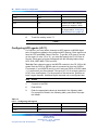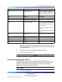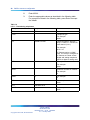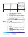
1
Nortel CallPilot
Quickstart Guide
NN44200-313
.
Document status: Standard
Document version: 01.02
Document date: 19 May 2008
Copyright © 2007-2008, Nortel Networks
All Rights Reserved.
Sourced in Canada.
Information is subject to change without notice. Nortel Networks reserves the right to make changes in design or
components as progress in engineering and manufacturing may warrant.
The process of transmitting data and call messaging between CallPilot and its servers, switches or system is
proprietary to Nortel Networks. Any other use of the data and the transmission process is a violation of the user
license unless specifically authorized in writing by Nortel Networks prior to such use. Violations of the license by
alternative usage of any portion of this process or the related hardware constitutes grounds for an immediate
termination of the license and Nortel Networks reserves the right to seek all allowable remedies for such breach.
Nortel Networks and third-party trademarks appear on the following pages:
*Nortel, the Nortel logo, the Globemark, and Unified Networks, BNR, CallPilot, DMS, DMS-100, DMS-250,
DMS-MTX, DMS-SCP, DPN, Dualmode, Helmsman, IVR, MAP, Meridian, Meridian 1, Meridian Link, Meridian Mail,
Norstar, SL-1, SL-100, Succession, Supernode, Symposium, Telesis, and Unity are trademarks of Nortel Networks.
3COM is a trademark of 3Com Corporation.
ACCENT is a trademark of Accent Software International Ltd.
ADOBE is a trademark of Adobe Systems Incorporated.
AMDEK is a trademark of Amdek Corporation.
AT&T is a trademark of American Telephone and Telegraph Corporation.
ATLAS is a trademark of Quantum Corporation.
ATRIA is a trademark of Pure Atria Corporation.
BLACKBERRY is a trademark of Research in Motion Limited.
CASEWARE is a trademark of Caseware International, Inc.
CONTINUUS is a trademark of Continuus Software Corporation.
CRYSTAL REPORTS is a trademark of Seagate Software Inc.
DEFINITY is a trademark of Avaya Inc.
DIALOGIC, INTEL and VOICEBRIDGE are trademarks of Intel Corporation.
DIVX is a trademark of DivXNetworks, Inc.
EUDORA and QUALCOMM are trademarks of Qualcomm, Inc.
eTrust and InoculateIT are trademarks of Computer Associates Think Inc.
DIRECTX, EXCHANGE.NET, FRONTPAGE, INTERNET EXPLORER, LINKEXCHANGE, MICROSOFT,
MICROSOFT EXCHANGE SERVER, MS-DOS, NETMEETING, OUTLOOK, POWERPOINT, VISUAL STUDIO,
WINDOWS, WINDOWS MEDIA, and WINDOWS NT are trademarks of Microsoft Corporation.
GROUPWISE and NOVELL are trademarks of Novell Inc.
HITACHI is a trademark of Hitachi Limited.
LOGITECH is a trademark of Logitech, Inc.
LUCENT is a trademark of Lucent Technologies, Inc.
MATRA is a trademark of Matra Hachette.
MCAFFEE and NETSHIELD are trademarks of McAfee Associates, Inc.
MYLEX is a trademark of Mylex Corporation.
NET2PHONE is a trademark of Net2Phone, Inc.
NETOPIA is a trademark of Netopia, Inc.
NETSCAPE COMMUNICATOR is a trademark of Netscape Communications Corporation.
NOTES is a trademark of Lotus Development Corporation.
NORTON ANTIVIRUS and PCANYWHERE are trademarks of Symantec Corporation.
POWERQUEST is a trademark of PowerQuest Corporation.
PROMARK and RHOBOT are trademarks of DMI Promark, Inc.
QUICKTIME is a trademark of Apple Computer, In.
RADISYS is a trademark of Radisys Corporation.
ROLM is a trademark of Siemens ROLM Communications Inc.
SLR4, SLR5, and TANDBERG are trademarks of Tandberg Data ASA.
SONY is a trademark of Sony Corporation.
SYBASE is a trademark of Sybase, Inc.
TEAC is a trademark of TEAC Corporation.
UNIX is a trademark of X/Open Company Limited.
US ROBOTICS, the US ROBOTICS logo, and SPORTSTER are trademarks of US Robotics.
WINAMP is a trademark of Nullsoft, Inc.
WINRUNNER is a trademark of Mercury Interactive Corporation.
5
Contents
How to get help
7
Getting help from the Nortel Web site 7
Getting help over the phone from a Nortel Solutions Center 7
Getting help from a specialist by using an Express Routing Code 7
Getting help through a Nortel distributor or reseller 8
CallPilot 5.0 installation
Prerequisites to CallPilot 5.0 installation
CallPilot 5.0 installation tasks 10
Time requirements 11
9
9
CS 1000/M1 system status check
CS 1000/M1 system status check tasks 13
Checking the current IP address of the PBX (LD 117) 14
Checking the currently configured VAS IDs 14
Checking the ELAN interface status of the PBX (LD 137) 15
Enabling the ELAN interface of the PBX (LD 137) 15
Checking the status of the ELAN connection to the PBX (LD 48)
CallPilot resource configuration
13
15
17
CallPilot resource configuration tasks 17
Configuring a new ELAN ID and VAS ID (LD 17) 18
Configuring system parameters (LD 17) 19
Defining CallPilot in the customer data block (LD 15) 20
Configuring the Route Data Block (LD 16) 22
Configuring Automatic Call Distribution (LD 23) 23
Configuring the DFDN (LD 23) 24
Configuring the CDN queue (LD 23) 25
Configuring ACD agents (LD 11) 26
Provisioning telephones (LD 11) 27
Enabling card slots (LD 32) 29
Saving CS 1000/M1 changes (LD 43) 30
CallPilot server general description
600r CallPilot server
Front panel 31
Back panel 32
31
Nortel CallPilot
Quickstart Guide
NN44200-313 01.02 Standard
5.0 19 May 2008
Copyright © 2007-2008, Nortel Networks
.
31
6 Contents
1005r CallPilot server
Front panel 33
Back panel 35
33
CallPilot server preinstallation
Recommended tools 37
CallPilot server preinstallation tasks
Choosing a location 38
Preparing the site 38
Connecting to the network 39
Unpacking the server 39
37
38
CallPilot server installation
CallPilot server installation tasks 41
Rack-mounting the server 41
Installing peripheral devices 42
Installing cables and grounds 43
Performing preboot checks 45
Connecting the server to power and starting it
41
45
CallPilot server configuration
47
CallPilot server configuration tasks 47
Logging on to the CallPilot server 47
Completing the Setup Wizard and installing PEPs 47
Running the Configuration Wizard 49
Configuring new mailboxes and additional tasks 52
Backing up the system 53
CallPilot server testing
CallPilot server testing tasks 55
Checking CallPilot connectivity and channels 55
Verifying that you can log on to mailboxes 56
Verifying that you can leave a message 57
Verifying that you can retrieve a message 57
Verifying that each CallPilot channel is functioning correctly
Testing pcAnywhere using a remote PC 58
What is next? 59
57
Installing the CallPilot 5.0 image
61
Configuring phantom DNs
63
Nortel CallPilot
Quickstart Guide
NN44200-313 01.02 Standard
5.0 19 May 2008
Copyright © 2007-2008, Nortel Networks
.
55
7
How to get help
This chapter explains how to get help for Nortel products and services.
Getting help from the Nortel Web site
The best way to get technical support for Nortel products is from the Nortel
Technical Support Web site:
www.nortel.com/support
This site provides quick access to software, documentation, bulletins, and
tools to address issues with Nortel products. From this site, you can:
•
download software, documentation, and product bulletins
•
search the Technical Support Web site and the Nortel Knowledge Base
for answers to technical issues
•
sign up for automatic notification of new software and documentation
for Nortel equipment
•
open and manage technical support cases
Getting help over the phone from a Nortel Solutions Center
If you do not find the information you require on the Nortel Technical Support
Web site, and you have a Nortel support contract, you can also get help
over the phone from a Nortel Solutions Center.
In North America, call 1-800-4NORTEL (1-800-466-7835).
Outside North America, go to the following Web site to obtain the phone
number for your region:
www.nortel.com/callus
Getting help from a specialist by using an Express Routing Code
To access some Nortel Technical Solutions Centers, you can use an Express
Routing Code (ERC) to quickly route your call to a specialist in your Nortel
product or service. To locate the ERC for your product or service, go to:
Nortel CallPilot
Quickstart Guide
NN44200-313 01.02 Standard
5.0 19 May 2008
Copyright © 2007-2008, Nortel Networks
.
8 How to get help
www.nortel.com/erc
Getting help through a Nortel distributor or reseller
If you purchase a service contract for your Nortel product from a distributor
or authorized reseller, you can contact the technical support staff for that
distributor or reseller.
Nortel CallPilot
Quickstart Guide
NN44200-313 01.02 Standard
5.0 19 May 2008
Copyright © 2007-2008, Nortel Networks
.
9
CallPilot 5.0 installation
The CallPilot 5.0 Quickstart Guide provides basic instructions on new
hardware installation and basic configuration of a CallPilot 5.0 system. After
using this guide to set up a basic CallPilot configuration, you should be
able to dial a mailbox, leave a message and retrieve a message using the
telephone. For more detailed configuration information, see the appropriate
technical documentation.
This document is designed to be followed from start to finish and is intended
for experienced installers.
Prerequisites to CallPilot 5.0 installation
Before you proceed with installation of a CallPilot 5.0 system using this
guide, you should have the following knowledge and skills:
•
Understanding of basic programming and provisioning for CallPilot 5.0.
•
Understanding of basic programming and provisioning for the
Communication Server 1000 (CS 1000) or Meridian 1 (M1) system.
•
Knowledge of personal safety precautions to take to minimize risk of
injury when installing components.
DANGER
Risk of injury by electric shock
To minimize risk of injury by electric shock, take care when
working with power equipment and connections.
DANGER
Risk of injury by laser
Never look directly into the end of a fiber cable or use an
optical device to look at the end of a fiber cable unless you are
certain that the other end of the cable is not connected. The
laser traveling through a fiber cable can injure the retina.
Nortel CallPilot
Quickstart Guide
NN44200-313 01.02 Standard
5.0 19 May 2008
Copyright © 2007-2008, Nortel Networks
.
10 CallPilot 5.0 installation
•
Understanding of electrostatic discharge and how to prevent it.
Electrostatic discharge (ESD) is the transfer of charge between
bodies at different electrical potentials. ESD can change the electrical
characteristics of a semiconductor device and degrade or destroy it.
ESD can also disrupt the normal operation of an electronic system by
causing equipment malfunction or failure. Follow these guidelines to
prevent ESD:
— To dissipate or neutralize electrostatic charges, use proper grounding
and use conductive or dissipative materials.
— When handling modules, always wear an antistatic wrist strap
connected to the same ESD grounding point as the equipment being
worked on. Any charge in your body will go to ground rather than
transferring to hardware modules.
— Always set modules on appropriate antistatic material. Proper
antistatic packaging effectively shields the product from charge
and reduces the generation of charge caused by movement of the
product within the container.
•
Knowledge of general practices to protect equipment modules from
damage. Follow these guidelines to prevent damage to equipment
modules:
— Handle modules by the faceplate. Do not touch pins or electrical
connections.
— Do not leave slots open. All slots must be filled with modules or
be covered with slot covers, if empty, in order to maintain safety
compliance, proper cooling, and EMI containment in the shelf.
— Ensure that your environment meets the necessary requirements for
temperature, humidity, and cleanliness. Refer to the environmental
requirements for your switch and server in the CallPilot server
configuration guide for your switch model.
— Replace the optional air filter regularly (approximately every three
months) in order to maintain proper cooling and airflow through the
shelf.
— Do not over-tighten thumb screws or lug nuts. Tighten until snug
plus a quarter turn. If you use a power tool to tighten screws, use a
low torque setting (2–3 lbs/sq in).
CallPilot 5.0 installation tasks
The following is a list of the CallPilot 5.0 installation tasks covered in this
guide, listed in the correct sequence. To link to detailed procedures for
each task, click the text.
•
"CS 1000/M1 system status check tasks" (page 13)
Nortel CallPilot
Quickstart Guide
NN44200-313 01.02 Standard
5.0 19 May 2008
Copyright © 2007-2008, Nortel Networks
.
Time requirements
•
"CallPilot resource configuration" (page 17)
•
"CallPilot server preinstallation" (page 37)
•
"CallPilot server installation" (page 41)
•
"CallPilot server configuration" (page 47)
•
"CallPilot server testing" (page 55)
11
Time requirements
The following table shows the approximate time required to complete each
task in the work flow.
Table 1
Time requirements
Task
Time to completion
CS 1000/M1 system status check
15 minutes
CallPilot resource configuration
2 hours
CallPilot server preinstallation
1 hour
CallPilot server installation
1 hour
CallPilot server configuration
2 hours
CallPilot server testing
1.5 hours
Total time to completion =
7 hours 45 minutes
Nortel CallPilot
Quickstart Guide
NN44200-313 01.02 Standard
5.0 19 May 2008
Copyright © 2007-2008, Nortel Networks
.
12 CallPilot 5.0 installation
Nortel CallPilot
Quickstart Guide
NN44200-313 01.02 Standard
5.0 19 May 2008
Copyright © 2007-2008, Nortel Networks
.
13
CS 1000/M1 system status check
This task describes how to check the Communication Server 1000 (CS
1000) or the Meridian 1 (M1) system status.
To successfully install a basic CallPilot system, you must provision or verify
the following parameters on the telephony switch (CS 1000 or M1):
•
PBX IP and host name
•
VAS ID
•
ELAN ID
•
system parameters
•
ACD
•
DFDN
•
CDN
•
ACD agents
•
telephones
CallPilot can be provided only on a per-customer basis on the CS 1000
or M1 system. ELAN messages used for communication between the
telephony switch and CallPilot contain a customer number to which CallPilot
belongs. In these procedures, ensure that you enter the correct customer
number in the overlays.
CS 1000/M1 system status check tasks
The following is a list of tasks you perform to check the status of the CS 1000
or M1 system. To link to detailed procedures for each task, click the text.
•
"Checking the current IP address of the PBX (LD 117)" (page 14)
•
"Checking the currently configured VAS IDs" (page 14)
•
"Checking the ELAN interface status of the PBX (LD 137)" (page 15)
•
"Enabling the ELAN interface of the PBX (LD 137)" (page 15)
Nortel CallPilot
Quickstart Guide
NN44200-313 01.02 Standard
5.0 19 May 2008
Copyright © 2007-2008, Nortel Networks
.
14 CS 1000/M1 system status check
•
"Checking the status of the ELAN connection to the PBX (LD 48)" (page
15)
Checking the current IP address of the PBX (LD 117)
Perform the following procedure to check the current IP address in the CS
1000 or M1 system.
Step
Action
1
Connect to the PBX.
2
If you have not already done so, log on using the proper account
with the following syntax:
logi <login name>
3
Press Enter.
4
At the prompt, type the password for the login name and press Enter.
5
Enter LD 117.
6
Enter STAT HOST to display the IP addresses and host names
configured in the CS 1000 or M1 system.
Note: If there is no IP provisioning completed, see the CS 1000
System and CallPilot Server Configuration guide (NN44200-312)
for advanced provisioning. When provisioning is complete, return
to this guide and continue to the next procedure.
7
To exit the overlay, enter ****.
—End—
Checking the currently configured VAS IDs
Step
Action
1
Connect to the PBX.
2
Enter LD 22.
3
At the REQ prompt, enter PRT.
4
At the TYPE prompt, enter VAS.
5
If there are some VAS IDs provisioned, take note of the VAS ID
information. If there are no VAS IDs provisioned, this guide explains
the steps to provision them in the next chapter.
Nortel CallPilot
Quickstart Guide
NN44200-313 01.02 Standard
5.0 19 May 2008
Copyright © 2007-2008, Nortel Networks
.
Checking the status of the ELAN connection to the PBX (LD 48)
15
—End—
Checking the ELAN interface status of the PBX (LD 137)
Perform the following procedure to check the ELAN interface status.
Step
Action
1
Connect to the PBX.
2
Enter LD 137.
3
Enter STAT ELNK. The status of the ELAN interface appears.
Note: If the ELAN interface is not configured, continue to
"Enabling the ELAN interface of the PBX (LD 137)" (page 15).
If it is configured, continue to "Checking the status of the ELAN
connection to the PBX (LD 48)" (page 15).
4
To exit the overlay, enter ****.
—End—
Enabling the ELAN interface of the PBX (LD 137)
Perform the following procedure to enable the ELAN interface. If it is already
enabled, skip to the next procedure.
Step
Action
1
Connect to the PBX.
2
Enter LD 137.
3
Enter CHG ELNK ACTIVE NAME, where NAME is the host name
for the primary IP address.
4
To exit the overlay, enter ****.
—End—
Checking the status of the ELAN connection to the PBX (LD 48)
Perform the following procedure to check the status of the ELAN connection
to the PBX.
Nortel CallPilot
Quickstart Guide
NN44200-313 01.02 Standard
5.0 19 May 2008
Copyright © 2007-2008, Nortel Networks
.
16 CS 1000/M1 system status check
Step
Action
1
Connect to the PBX.
2
Enter LD 48.
3
Enter STAT ELAN to display a list of current AML links.
Note: Take note of any enabled and active ELANs. This will be
useful when deciding if a new VAS ID and ELAN ID are required.
4
To exit the overlay, enter ****.
—End—
Nortel CallPilot
Quickstart Guide
NN44200-313 01.02 Standard
5.0 19 May 2008
Copyright © 2007-2008, Nortel Networks
.
17
CallPilot resource configuration
This task describes how to configure CallPilot 5.0 resources on the
Communication Server 1000 (CS 1000) or Meridian 1 (M1) system.
CallPilot can be provided only on a per-customer basis on the CS 1000
or M1 system. AML messages used for communications between the
telephony switch and CallPilot contain a customer number to which CallPilot
belongs. In these procedures, ensure that you enter the correct customer
number in the overlays.
CallPilot resource configuration tasks
The following is a list of tasks you perform to configure CallPilot 5.0
resources on the CS 1000 or M1 system. To link to detailed procedures
for each task, click the text.
•
"Configuring a new ELAN ID and VAS ID (LD 17)" (page 18)
•
"Configuring system parameters (LD 17)" (page 19)
•
"Defining CallPilot in the customer data block (LD 15)" (page 20)
•
"Configuring the Route Data Block (LD 16)" (page 22)
•
"Configuring Automatic Call Distribution (LD 23)" (page 23)
•
"Configuring the DFDN (LD 23)" (page 24)
•
"Configuring the CDN queue (LD 23)" (page 25)
•
"Configuring ACD agents (LD 11)" (page 26)
•
"Provisioning telephones (LD 11)" (page 27)
•
"Enabling card slots (LD 32)" (page 29)
•
"Saving CS 1000/M1 changes (LD 43)" (page 30)
Nortel CallPilot
Quickstart Guide
NN44200-313 01.02 Standard
5.0 19 May 2008
Copyright © 2007-2008, Nortel Networks
.
18 CallPilot resource configuration
Configuring a new ELAN ID and VAS ID (LD 17)
Define and configure the ELAN subnet for the AML link and its associated
VAS ID in the configuration record. This provides the Ethernet connection
over which AML messages are exchanged between the CS 1000 or M1
system and CallPilot. A separate ELAN must be created for CallPilot and
Contact Center for the purpose of integration.
Perform this procedure only if there is no VAS ID provisioned or available.
Step
Action
1
Connect to the PBX.
2
Enter LD 17.
3
Enter the appropriate values as described in the following table to
configure a new ELAN ID. For prompts not listed in the following
table, press Enter to accept the default.
Table 2
LD 17 - Configuring the ELAN ID
Prompt
Response
REQ
CHG
TYPE
ADAN
ADAN
NEW ELAN xx
CTYP
ELAN
DES
a..a
LCTL
<cr>
4
Notes
Where xx is the next available
number, 16 – 31.
Enter a relevant description (for
example, CallPilot).
Enter the appropriate values as described in the following table to
configure a new VAS ID. For prompts not listed in the following table,
press Enter to accept the default.
Table 3
LD 17 - Configuring the VAS ID
Prompt
Response
REQ
CHG
TYPE
VAS
VAS
NEW
VSID
xx
Nortel CallPilot
Quickstart Guide
NN44200-313 01.02 Standard
5.0 19 May 2008
Copyright © 2007-2008, Nortel Networks
.
Notes
Enter the number entered for
the ELAN ID above.
Configuring system parameters (LD 17)
Prompt
Response
Notes
ELAN
xx
Enter the number entered for
the ELAN ID above.
SECU
YES
5
19
To exit the overlay, enter ****.
Tech tip: To view the new ELAN, enter LD 22. Enter PRT at the REQ
prompt, then ADAN. A list of all provisioned IDs appears. Use the
capture text function in hyperterminal to save a text file of the output.
—End—
Configuring system parameters (LD 17)
Tech tip: To view a list of all provisioned system parameters, enter LD 22
and enter PRT at the REQ prompt, then CFN. Use the capture text function
in hyperterminal to save a text file of the output.
Step
Action
1
Connect to the PBX.
2
Enter LD 17.
3
Enter the appropriate values as described in the following table.
For prompts not listed in the following table, press Enter to accept
the default.
Table 4
LD 17 - Configuring system parameters
Prompt
Response
REQ
CHG
TYPE
PARM
NCR
xxx
Notes
Enter the number of DS0
channels multiplied by 2 plus
the current NCR.
For example, if the current NCR
is 500 and there are 24 DS0
channels, enter 548.
Nortel CallPilot
Quickstart Guide
NN44200-313 01.02 Standard
5.0 19 May 2008
Copyright © 2007-2008, Nortel Networks
.
20 CallPilot resource configuration
Prompt
Response
Notes
CSQI
xxx
Enter the number of CallPilot
DS0 channels multiplied by 2.
For example, if there are 24
DS0 channels, enter 48.
xxx
CSQO
Enter the number of CallPilot
DS0 channels multiplied by 2.
For example, if there are 24
DS0 channels, enter 48.
4
To exit the overlay, enter ****.
—End—
Defining CallPilot in the customer data block (LD 15)
Tech tip: To view current system parameters, go to LD 21 and enter PRT at
the REQ prompt, and then CDB and the appropriate customer number. The
result is a list of all the current information in the Customer Data Block. Use
the capture text function in hyperterminal to save a text file of the output.
Step
Action
1
Connect to the PBX.
2
Enter LD 15.
3
Enter the appropriate values as described in the following table to
add Call Park Allowed and Message Center Included. For prompts
not listed in the following table, press Enter to accept the default.
Table 5
LD 15 - Configuring Call Park Allowed and Message Center Included
Prompt
Response
REQ
CHG
TYPE
ftr
CUST
xx
OPT
CPA MCI
IDEF
YES
NO
Notes
Customer number for CallPilot.
If Call Forward by Call Type
(CFCT) is enabled on the CS
1000 or M1 switch, enter YES.
Otherwise, enter NO.
Nortel CallPilot
Quickstart Guide
NN44200-313 01.02 Standard
5.0 19 May 2008
Copyright © 2007-2008, Nortel Networks
.
Defining CallPilot in the customer data block (LD 15)
4
21
Enter the appropriate values as described in the following table to
define Call Redirection. For prompts not listed in the following table,
press Enter to accept the default.
Table 6
LD 15 - Configuring Call Redirection
Prompt
Response
REQ
CHG
TYPE
rdr
CUST
xx
Customer number for CallPilot.
FNAD
xxxx
Enter the FDN for CallPilot.
FNAT
xxxx
Enter the FDN for CallPilot.
FNAL
xxxx
Enter the FDN for CallPilot.
CFNA
4
CFN0
1-(4)-15
Number of normal ringing cycles
for CFNA, Option 0.
CFN1
1-(4)-15
Number of normal ringing cycles
for CFNA, Option 1.
CFN2
1-(4)-15
Number of normal ringing cycles
for CFNA, Option 2.
5
Notes
Enter the appropriate values as described in the following table to
define End-to-End Signaling Tone. For prompts not listed in the
following table, press Enter to accept the default.
Table 7
LD 15 - Configuring End-to-End Signaling Tone
Prompt
Response
REQ
CHG
TYPE
ftr
CUST
xx
Customer number for CallPilot.
EEST
YES
Enter NO if remote sites are set
to NO.
NO
6
Enter the appropriate values as described in the following table to
define Integrated Services Digital Network. For prompts not listed in
the following table, press Enter to accept the default.
Nortel CallPilot
Quickstart Guide
NN44200-313 01.02 Standard
5.0 19 May 2008
Copyright © 2007-2008, Nortel Networks
.
Notes
22 CallPilot resource configuration
Table 8
LD 15 - Configuring Integrated Services Digital Network
Prompt
Response
Notes
REQ
CHG
TYPE
net
CUST
xx
Customer number for CallPilot.
ISDN
YES
Enter NO if NMS is not installed
on the CS 1000 or M1 system.
NO
xxxxx
PNI
Private Network Identifier.
Within one network, use the
same PNI value in LDs 15 and
16. When you interwork with
different networks, enter the
PNI of this CS 1000 or M1
system in LD 15, and the PNI of
the target or remote CS 1000 or
M1 system in LD 16.
The default PNI = 0 prevents
the operations of features such
as NRAG, NACD and NMS.
HLOC
xxxx
Home Location Code defined in
LD 90.
LSC
xxxx
Local Steering Code defined in
LD 15.
7
To exit the overlay, enter ****.
Tech tip: To view a list of installed packages, enter LD 22 and enter
PRT at the REQ prompt, then PKG. Use the capture text function in
hyperterminal to save a text file of the output.
—End—
Configuring the Route Data Block (LD 16)
Perform the following procedure to configure the Route Data Block.
Step
Action
1
Connect to the PBX.
2
Enter LD 16.
Nortel CallPilot
Quickstart Guide
NN44200-313 01.02 Standard
5.0 19 May 2008
Copyright © 2007-2008, Nortel Networks
.
Configuring Automatic Call Distribution (LD 23)
3
23
Enter the appropriate values as described in the following table.
For prompts not listed in the following table, press Enter to accept
the default.
Table 9
LD 16 - Configuring the Route Data Block
Prompt
Response
REQ
CHG
TYPE
rdb
CUST
xx
Customer number for CallPilot.
ROUTE
xxx
Enter the number of the route
you wish to modify.
DES
aaa
Description for the route.
IDEF
LOC
RCLS
EXT
4
Notes
To exit the overlay, enter ****.
Tech tip: To view all configured routes, enter LD 21. Enter PRT at
the REQ prompt, RDB, and then the customer number, and press
Enter through the remaining prompts. Use the capture text function
in hyperterminal to save a text file of the output.
—End—
Configuring Automatic Call Distribution (LD 23)
Configure only one ACD agent queue to service CallPilot, unless you are
enabling the Symposium Voice Services Support feature. This queue holds
all the agents that correspond to DS0 channels on the CallPilot server.
Step
Action
1
Connect to the PBX.
2
Enter LD 23.
3
Enter the appropriate values as described in the following table.
For prompts not listed in the following table, press Enter to accept
the default.
Nortel CallPilot
Quickstart Guide
NN44200-313 01.02 Standard
5.0 19 May 2008
Copyright © 2007-2008, Nortel Networks
.
24 CallPilot resource configuration
Table 10
LD 23 - Configuring Automatic Call Distribution
Prompt
Response
REQ
NEW
TYPE
ACD
CUST
xx
Customer number for CallPilot.
ACDN
xxxx
This is the ACD DN the agents
point at.
MWC
NO
MAXP
xxxx
CALP
POS
IVR
YES
ALOG
YES
4
Notes
Maximum number of agent
channels.
To exit the overlay, enter ****.
—End—
Configuring the DFDN (LD 23)
Before you configure the CDN queue, define the default ACD DN to be
referenced in the CDN. During normal operation, the CDN is in control
mode, and callers are queued to be routed and then answered by CallPilot
services. Under error conditions (for example, if the AML link is down), the
CDN operates in default mode and calls are routed to the default ACD DN
defined for the CDN.
This procedure describes how to set up the default ACD DN so that these
calls are handled by the attendant. For the attendant to process incoming
calls to CallPilot when the CDN is in default mode, define a dummy ACD DN
and set it to night call forward to the attendant.
Step
Action
1
Connect to the PBX.
2
Enter LD 23.
3
Enter the appropriate values as described in the following table.
For prompts not listed in the following table, press Enter to accept
the default.
Nortel CallPilot
Quickstart Guide
NN44200-313 01.02 Standard
5.0 19 May 2008
Copyright © 2007-2008, Nortel Networks
.
Configuring the CDN queue (LD 23)
25
Table 11
LD 23 - Configuring DFDN
Prompt
Response
Notes
REQ
NEW
TYPE
ACD
CUST
xx
Customer number for CallPilot.
ACDN
xxxx
Enter the DFDN.
MWC
NO
MAXP
1
Maximum number of agent
channels.
Enter 1 to make this a DFDN
queue.
0
NCFW
4
To exit the overlay, enter ****.
—End—
Configuring the CDN queue (LD 23)
The control DN is the single point to which the end user calls to access
voice mail or use multimedia functions such as fax capabilities.
Perform this procedure to configure the following CDN queues:
•
primary CDN for Voice Messaging. This becomes the main CDN queue.
•
secondary CDN for Multimedia Messaging, if you want to provide users
with fax capability.
Step
Action
1
Connect to the PBX.
2
Enter LD 23.
3
Enter the appropriate values as described in the following table.
For prompts not listed in the following table, press Enter to accept
the default.
Table 12
LD 23 - Configuring the CDN queue
Prompt
Response
REQ
NEW
Nortel CallPilot
Quickstart Guide
NN44200-313 01.02 Standard
5.0 19 May 2008
Copyright © 2007-2008, Nortel Networks
.
Notes
26 CallPilot resource configuration
Prompt
Response
TYPE
CDN
CUST
xx
Customer number for CallPilot.
CDN
xxxx
Control DN of the CallPilot
system (for example, 4300).
DFDN
xxxx
The default ACD created above,
in the procedure "Configuring
the DFDN (LD 23)" (page 24).
4
Notes
To exit the overlay, enter ****.
—End—
Configuring ACD agents (LD 11)
For CallPilot, you must define channels as ACD agents on M2008 digital
sets. All agents are added to the configured ACD queues. Each agent must
have the VCE and MMA Class of Service. To get the VCE class of service
on the upper 16 units (15 to 31), you must first specify the FLXA Class of
Service. Each agent must be provisioned with the following feature keys:
ACD, SCN, NRD, MSB, TRN, and AO3.
Tech tip: Each channel maps to the MGATE card slot in the CS 1000 or M1
system that the DS30 or DS30X cable is connected to from the CallPilot.
For example, if your MGATE card is in slot 8 and your DS30 or DS30X cable
1-1 is connected, your first channel TN may be 4.0.1.0 for a large system or
0.0.8.0 for a small system. For the purpose of this document, provision at
least 2 agent channels. Additional agent channels can be configured later.
Step
Action
1
Connect to the PBX.
2
Enter LD 11.
3
Enter the appropriate values as described in the following table.
For prompts not listed in the following table, press Enter to accept
the default.
Table 13
LD 11 - Configuring ACD agents
Prompt
Response
REQ
NEW
TYPE
2008
Nortel CallPilot
Quickstart Guide
NN44200-313 01.02 Standard
5.0 19 May 2008
Copyright © 2007-2008, Nortel Networks
.
Notes
Provisioning telephones (LD 11)
27
Prompt
Response
Notes
TN
aaa.bbb.ccc.ddd
Terminal Number, where a =
loop, b = shelf, c = MGATE card
slot, d = channel for that card
(0–31).
DES
dddddd
Description.
CUST
xx
Customer number for CallPilot.
CLS
WTA UNR VCE MMA FLAX
KEY
0 ACD xxxx 0 yyyy
xxxx = the ACD defined above
in the procedure "Configuring
Automatic Call Distribution (LD
23)" (page 23).
yyyy = the position ID of the
agent,
For example: KEY: 0 ACD 4500
0 4571
KEY
1 SCN xxxx
KEY
2 MSB
KEY
3 NRD
KEY
4 TRN
KEY
5 AO3
xxxx = Single Call Non ringing
DN
Tech tip: Take note of the TN, Key 0 position ID, and Key 1 SCN
configured here. These parameters are required later in the CallPilot
server configuration.
4
Repeat step 3 for each ACD agent channel required.
5
To exit the overlay, enter ****.
—End—
Provisioning telephones (LD 11)
In the examples in this procedure, an i2004 Model NTDU92 is used. To
configure other models, refer to IP Phones: Description, Installation, and
Operation (553-3001-368) and Telephones & Consoles: Description,
Installation and Operation (553-3001-367)
Step
Action
1
Connect to the PBX.
Nortel CallPilot
Quickstart Guide
NN44200-313 01.02 Standard
5.0 19 May 2008
Copyright © 2007-2008, Nortel Networks
.
28 CallPilot resource configuration
2
Enter LD 11.
3
Enter the appropriate values as described in the following table.
For prompts not listed in the following table, press Enter to accept
the default.
Table 14
LD 11 - Provisioning telephones
Prompt
Response
REQ
NEW
TYPE
a..a
Notes
Telephone type
For example:
i2004
TN
aaa.bbb.ccc.ddd
Terminal Number, where a =
loop, b = shelf, c = card slot, d =
card channel (0–31).
For example:
66 0 0 10
IP Phones require a VGMC
card. The TNs you configure for
IP Phones are virtual circuits.
Digital and analog telephones
require a digital or analog card.
DES
dddddd
Description.
For example:
johns
CUST
xx
Customer number for CallPilot.
For example:
0
ZONE
xx
For example:
0
FDN
xxxx
For example:
4300
CLS
FNA MWA HTA
HUNT
xxxx
Nortel CallPilot
Quickstart Guide
NN44200-313 01.02 Standard
5.0 19 May 2008
Copyright © 2007-2008, Nortel Networks
.
For example:
4300
Enabling card slots (LD 32)
29
Prompt
Response
Notes
KEY
0 SCR xxxx
Where xxxx is the line number
of the telephone. This is the
number dialled or the line
selected when the user makes
a call from the telephone.
For example:
4710
KEY
16 MWK xxxx
Where xxxx is the CDN of the
CallPilot system.
For example:
4300
4
Repeat step 3 for each telephone to be configured.
Configure at least two telephones for testing purposes.
5
To exit the overlay, enter ****.
6
Connect two telephones to either a phone line or a proper network
connection, depending on the telephone type. Refer to the user
guides specific to the telephones.
7
Ensure that you have dial tone on both telephones, and check that
you can dial one phone from the other.
—End—
Enabling card slots (LD 32)
If the MGATE card slots are not automatically provisioned, perform the
following procedure to enable them.
Step
Action
1
Connect to the PBX.
2
Enter LD 32.
3
To display the status of the MGATE card, enter STAT n (where n is
the card slot used by the MGATE).
For example: STAT 18.
4
If the MGATE card is disabled, enter ENLC n (where n is the card
slot used by the MGATE) to enable it.
For example: ENLC 18.
5
Repeat steps 3 and 4 for each required MGATE card.
Nortel CallPilot
Quickstart Guide
NN44200-313 01.02 Standard
5.0 19 May 2008
Copyright © 2007-2008, Nortel Networks
.
30 CallPilot resource configuration
6
To exit the overlay, enter ****.
—End—
Saving CS 1000/M1 changes (LD 43)
Perform the following procedure to save all configuration changes. If a
reboot occurs before you save the system, all your changes could be lost.
Tech tip: The prompt for LD 43 is just a period ".". Entering the command
EDD will complete a data dump to the on board flash.
Step
Action
1
Connect to the PBX.
2
Enter LD 43.
3
At the "." prompt, enter EDD.
4
To exit the overlay, enter ****.
—End—
Nortel CallPilot
Quickstart Guide
NN44200-313 01.02 Standard
5.0 19 May 2008
Copyright © 2007-2008, Nortel Networks
.
31
CallPilot server general description
This section describes the hardware components of the CallPilot servers.
For CallPilot Release 5.0, there are two server models: the 600r
CallPilot server and the 1005r CallPilot server. The 600r system is a
small-capacity system that can handle up to 20,000 mailboxes. The 1005r
is a large-capacity system that can handle up to 50,000 mailboxes. Both
servers are rack-mounted servers that fit into a standard 19” or 23” rack.
600r CallPilot server
Front panel
Figure 1 "600r CallPilot server - front panel" (page 31) shows the front panel
on the 600r. The front panel LEDs and control switches are highlighted in
Figure 2 "600r CallPilot server - front panel LEDs" (page 32) and Table 15
"600r CallPilot server - front panel LEDs" (page 32).
Figure 1
600r CallPilot server - front panel
Nortel CallPilot
Quickstart Guide
NN44200-313 01.02 Standard
5.0 19 May 2008
Copyright © 2007-2008, Nortel Networks
.
32 CallPilot server general description
Figure 2
600r CallPilot server - front panel LEDs
Table 15
600r CallPilot server - front panel LEDs
Label
Description
A
Power button
B
Reset button
C
Critical fault LED
D
Major fault LED
E
Minor fault LED
F
Power LED
G
Disk 0 activity/fault LED (green/amber)
H
Not used
I
Main power LED (green)
J
NIC activity LED (green)
K
System ID LED (white)
L
ID button
M
NMI button (not used)
Back panel
Figure 3 "600r CallPilot server - back panel" (page 33) shows the back panel
on the 600r. The back panel controls and features are described in Table 16
"600r CallPilot server - back panel controls and features" (page 33).
Nortel CallPilot
Quickstart Guide
NN44200-313 01.02 Standard
5.0 19 May 2008
Copyright © 2007-2008, Nortel Networks
.
1005r CallPilot server
33
Figure 3
600r CallPilot server - back panel
Table 16
600r CallPilot server - back panel controls and features
Label
Description
A
USB 0, USB1, USB2 (bottom to top)
B
PS/2 mouse input
C
SCSI port (requires terminator)
D
MPB96 card
E
Power supply
F
AC power input
G
Ground studs
H
ELAN input
I
Nortel server subnet (CLAN) input
J
Video input
K
COM1 DB-9 serial port
L
PS/2 keyboard input
1005r CallPilot server
Front panel
Figure 4 "1005r CallPilot server - front panel" (page 34) shows the front panel
on the 1005r. The front panel LEDs and control switches are described in
Table 17 "1005r CallPilot server - front panel LEDs and controls" (page 34).
Nortel CallPilot
Quickstart Guide
NN44200-313 01.02 Standard
5.0 19 May 2008
Copyright © 2007-2008, Nortel Networks
.
34 CallPilot server general description
Figure 4
1005r CallPilot server - front panel
Table 17
1005r CallPilot server - front panel LEDs and controls
Label
Description
A
Power button
B
Reset button
C
Critical alarm LED
D
Major alarm LED
E
Minor alarm LED
F
Power alarm LED
G
NMI switch (not used)
H
ID switch
I
ID LED
J
NIC activity LED
K
Status LED
L
Hard drive 1 activity and status
M
Hard drive 0 activity and status
N
DVD/CD/CD-RW
O
RJ45 COM1 serial port
P
USB 2
Q
ESD connection
Nortel CallPilot
Quickstart Guide
NN44200-313 01.02 Standard
5.0 19 May 2008
Copyright © 2007-2008, Nortel Networks
.
1005r CallPilot server
Label
Description
R
Hard drive 1 pull handle
S
Hard drive 1 release lever
T
Hard drive 0 pull handle
U
Hard drive 0 release level
35
Back panel
Figure 5 "1005r CallPilot server - back panel" (page 35) shows the back
panel on the 1005r. The back panel controls and features are described in
Table 18 "1005r CallPilot server - back panel controls and features" (page
35).
Figure 5
1005r CallPilot server - back panel
Table 18
1005r CallPilot server - back panel controls and features
Label
Description
A
DB15 Telco alarm connector (not used)
B
PCI low profile cards (1, 2, 3 from bottom to top)
C
MPB 96 cards (1, 2, 3 from bottom to top)
D
Power supply 1
E
Power supply 2
F
PS/2 mouse and keyboard input
G
RJ45 COM2 serial port
H
Nortel server subnet (CLAN) input
I
ELAN input
J
Video input
K
USB 1
Nortel CallPilot
Quickstart Guide
NN44200-313 01.02 Standard
5.0 19 May 2008
Copyright © 2007-2008, Nortel Networks
.
36 CallPilot server general description
Label
Description
L
USB 0 (dongle connects here)
M
Server management LAN port
N
SCSI port (does not require terminator)
Nortel CallPilot
Quickstart Guide
NN44200-313 01.02 Standard
5.0 19 May 2008
Copyright © 2007-2008, Nortel Networks
.
37
CallPilot server preinstallation
This task describes the CallPilot server preinstallation.
Recommended tools
•
The following is a list of recommended tools for the job:
— antistatic ESD wrist strap kit
— cordless power drill with various Phillips, Robertson, and nut driver
bits
— hand-held Phillips, Robertson and standard screwdrivers in various
sizes
— handheld hex nut drivers
— needle-nosed pliers
— tweezers
— tape measure
— flashlight
— cable tie wraps (various lengths, mainly small ones required)
— side cutters
— utility knife or box cutter
— RJ45 crimper with various dyes (if making phone and Ethernet
cables)
— null modem serial cable (for troubleshooting purposes)
— cable identification labels
— equipment log, to record system information (for example, model,
serial number, and installed options)
— pen and note pad
Nortel CallPilot
Quickstart Guide
NN44200-313 01.02 Standard
5.0 19 May 2008
Copyright © 2007-2008, Nortel Networks
.
38 CallPilot server preinstallation
CallPilot server preinstallation tasks
The following is a list of tasks you perform to prepare for CallPilot server
installation. To link to detailed procedures for each task, click the text.
•
"Choosing a location" (page 38)
•
"Preparing the site" (page 38)
•
"Connecting to the network" (page 39)
•
"Unpacking the server" (page 39)
Choosing a location
Choose a site for the CallPilot server by considering following factors:
•
The DS30 cables that connect the NTRH40CA MPB96 board on the
CallPilot server to the MGate card on the switch can be up to 600
meters (1968 feet) long. This allows you to install the CallPilot server in
a different building from the switch.
•
The DS30X cable that connects the NTRH40AA MPB96 board on the
CallPilot server to the MGATE card on the switch is 20 meters (60 feet)
long. The total distance from switch to CallPilot must be taken into
consideration. Include rack transitions, cable bends, and any routing
necessary in your calculations before you install.
•
A monitor, keyboard, and mouse are required to connect to the CallPilot
server for local console access. These peripherals should be located in
the same rack as the CallPilot server, or at least within visual distance of
the server’s status LEDs.
•
The area must have proper cooling and airflow. Consider installing a
shelf with perforated holes for the peripheral devices, above or below
the CallPilot server.
Preparing the site
Perform the following procedure to prepare the site for the CallPilot server.
Step
Action
1
Ensure that the site is clean and clear of any debris.
2
Place a table or secure surface near the install location of the
CallPilot server for unpacking and inspection.
The surface or table should be large enough to accommodate a .9 m
X .9 m (3’ X 3’) box weighing approximately 10.4 kg (23 lbs) for the
600r CallPilot server, or 20 kg (44 lbs) for the 1005r CallPilot server.
3
Place an Electrostatic Discharge (ESD) mat on the unpacking
surface.
Nortel CallPilot
Quickstart Guide
NN44200-313 01.02 Standard
5.0 19 May 2008
Copyright © 2007-2008, Nortel Networks
.
Unpacking the server
39
4
Install the rack, or ensure that a pre-existing rack is properly installed
with sufficient space for the CallPilot server and peripheral devices.
The 600r is a 1U form factor and the 1005r is a 2U form factor.
5
Ensure that an external analog phone line is available for the USB
modem.
6
Ensure that a single-point ground reference is available for all the
power outlets serving the CallPilot server and its peripherals.
—End—
Connecting to the network
The CallPilot server has two network connections: the ELAN network
interface for the ELAN subnet and the CLAN network interface for the Nortel
server subnet.
The ELAN subnet connects the CallPilot server to the CS 1000 or M1
switch. Install the ELAN subnet on the same network as the CS 1000 or
M1 switch you are using for the CallPilot system, as a dedicated Ethernet
switch or hub segregated from any other network.
The Nortel server subnet is used for the following features: Desktop
Messaging, CallPilot Reporter, My CallPilot, CallPilot Manager remote
access, and Application Builder.
Both the ELAN subnet and the Nortel server subnet use standard network
Ethernet Cat 5e cables. If cables are made on site, ensure that IEEE 802.3
standards are maintained and followed.
Unpacking the server
Perform the following procedure to unpack the CallPilot server.
As you unpack each item, check it off against the packing list.
Step
Action
1
Place the cardboard carton containing the CallPilot server on the
floor, close to the secure surface or table.
2
Open the box, carefully remove the server, and place it on the ESD
mat on the table or secure surface.
Check that the USB dongle with keycode and feature list is included,
and for the 600r model, ensure that a SCSI terminator is included.
3
Open the other boxes containing the peripheral devices and check
that the following devices are included:
Nortel CallPilot
Quickstart Guide
NN44200-313 01.02 Standard
5.0 19 May 2008
Copyright © 2007-2008, Nortel Networks
.
40 CallPilot server preinstallation
•
monitor
•
keyboard
•
mouse
•
USB modem
•
Tandberg tape drive
•
tapes
•
SCSI cable
•
power cords
Place the peripheral devices in a safe, secure area near the
installation site.
4
Open the software package and check that the following software is
included:
•
CallPilot image DVD for your system
•
CallPilot service Update/PEP CD
•
CallPilot Application CD
•
CallPilot Desktop CD
•
CallPilot My CallPilot CD
•
CallPilot Language Prompts CDs (3)
•
CallPilot Documentation CD
•
printed DTR documentation
Place the software in a safe, secure area near the installation site.
5
Inspect the server and peripheral devices. Do not discard the
CallPilot server box in case a return is necessary.
6
Locate the external SCSI terminator (included loose within the server
shipping carton). Connect the terminator to the rear SCSI port.
—End—
Nortel CallPilot
Quickstart Guide
NN44200-313 01.02 Standard
5.0 19 May 2008
Copyright © 2007-2008, Nortel Networks
.
41
CallPilot server installation
This task describes the CallPilot server installation.
CallPilot server installation tasks
The following is a list of tasks you perform to install the CallPilot server. To
link to detailed procedures for each task, click the text.
•
"Rack-mounting the server" (page 41)
•
"Installing peripheral devices" (page 42)
•
"Installing cables and grounds" (page 43)
•
"Performing preboot checks" (page 45)
•
"Connecting the server to power and starting it" (page 45)
Rack-mounting the server
Perform the following procedure for four- or two-post rack-mounting.
The CallPilot server includes installation instructions for the 19” and 23”
Universal Rack Mount kits. Refer to the those instructions for more details.
Step
Action
1
Attach the inner rail to the chassis on both sides.
2
Attach the front-tab mounting bracket to the chassis on both sides.
The bracket is reversible for a flush mount install.
3
Using the four outer studs, assemble the mounting brackets to the
outer rail. Insert the four thread covers of the 4 inner studs.
For a two-post install, flip the mounting brackets so they are facing in
to each other.
Tech tip: Hand-tighten the nuts at this stage so you can adjust the
distance for the server and rack.
4
Install the two outer rail subassemblies.
Eight mounting screws are required for a four-post install. For a
two-post install, six mounting screws are required.
Nortel CallPilot
Quickstart Guide
NN44200-313 01.02 Standard
5.0 19 May 2008
Copyright © 2007-2008, Nortel Networks
.
42 CallPilot server installation
5
Tighten all the nuts that you previously hand-tightened.
6
Slide the system into the rack.
Check that the inner rail fits together with the outer rail.
7
To secure the server in place, install screws in the front-tab mounting
bracket to the rail.
For a two-post install, install four screws through the clearance slots
in the side of the outer rail assembly into the inner rail.
—End—
Installing peripheral devices
Perform the following procedure to install the peripheral devices on the
CallPilot server.
Step
Action
1
Optionally, install a perforated shelf for the modem and Tandberg
tape drive to sit on.
Nortel recommends that you use a perforated shelf rather than
placing the modem and tape drive directly on the CallPilot server
equipment. The holes in the perforated shelf promote air flow and
cooling.
2
Place the modem and tape drive on the perforated shelf or, on an
alternative surface.
3
Connect one end of the USB cable into the modem. Connect the
other end of the USB cable into the rear panel of the server module:
USB 2 for the 600r CallPilot server, or USB 1 for the 1005r CallPilot
server.
4
Connect the analog phone line to the RJ-11 jack labeled TELCO
on the modem.
5
Connect one end of the SCSI cable to the tape drive. Connect the
other end of the SCSI cable to the SCSI port on the rear panel of
the CallPilot server.
Ensure that all connectors are tightened.
Note: You must remove the SCSI terminator before you can
connect the tape drive. Ensure that there is a terminator installed
on the tape drive.
The 600r hard drive and tape drive are on the same SCSI bus.
If a terminator is not installed in the loop, the hard drive may be
damaged when the system is powered up.
Nortel CallPilot
Quickstart Guide
NN44200-313 01.02 Standard
5.0 19 May 2008
Copyright © 2007-2008, Nortel Networks
.
Installing cables and grounds
43
6
Set the SCSI ID on the tape drive to 6.
7
Install the monitor, keyboard, and mouse in the same location as
the server.
If you are using a KVM-type box, ensure that you have visual contact
with the LEDs on the CallPilot server.
8
Plug the keyboard and mouse cables into the PS/2 connectors on
the rear panel according to the labels.
9
Plug the monitor into the video connector on the rear panel.
Tighten screws on the connector.
10
Install the USB dongle into USB port 0.
Ensure that the feature key is in place.
—End—
Installing cables and grounds
Perform the following procedure to install cables and grounds for the
CallPilot server.
This procedure assumes that the cable and RJ45 are terminated properly
according to IEEE 802 Ethernet standards and are of sufficient length. This
procedure does not cover Ethernet cables of customized length.
Step
Action
1
Install and connect the ELAN Ethernet cable to the NIC 2 connector
labeled on the back of the server from the ELAN hub or Ethernet
switch.
Or, use an Ethernet cross-over cable to connect directly to the CS
1000 or M1 switch. If you use this method, no device other than
CallPilot can connect to the ELAN subnet.
Note: Connect the CS 1000 or M1 switch ELAN to the same
subnet as the CallPilot server ELAN.
2
Install and connect the Ethernet cable for the Nortel server subnet
to the NIC 1 connector labeled on the back of the server from the
Nortel server subnet hub or Ethernet switch.
Not all sites require a Nortel server subnet; this subnet is used for
the following features: Desktop Messaging, CallPilot Reporter, My
CallPilot, CallPilot Manager remote access, and Application Builder.
Note: Leave the Ethernet cable for the Nortel server subnet
unplugged on the server side until antivirus software is installed
on the server.
Nortel CallPilot
Quickstart Guide
NN44200-313 01.02 Standard
5.0 19 May 2008
Copyright © 2007-2008, Nortel Networks
.
44 CallPilot server installation
3
Install the power cords to all devices, but plug them only into the
receptacle, not into the end device. The devices requiring power are:
•
1005r server — two power cords, redundant power supplies
•
600r server — one power cord
•
monitor — one power cord
•
tape drive — one power cord
•
ELAN subnet Ethernet switch or hub — one power cord
•
Nortel server subnet Ethernet switch or hub — one power cord
Note: The single-point ground (SPG) required by the system
can be an isolated ground (IG) bus or AC equipment ground
(ACEG) bus in the service panel or transformer. The system
must be connected to a safety ground or protective earth in
accordance with NEC requirements. For international use, the
system must be connected to safety ground or protective earth in
accordance with Paragraph 2.5 of EN60950/IEC950.
4
5
Check the version of your MPB96 card or cards before proceeding.
The versions are identified as follows:
•
The NTRH40CA MPB96 board has three RJ-45 connectors on
its faceplate. If you have an NTRH40CA, proceed to step 5.
•
The NTRH40AA MPB96 board has a single DB-44 connector on
its faceplate. The MPB96 connects to the MGate using a DS30X
cable. If you have an NTRH40AA, proceed to step 6.
Install and connect the DS30 cables from the switch MGATE card
to the CallPilot MPB96. There is no restriction as to which cable is
connected first, as the NTRH40AC MPB96 can get its timing from
any of the three RJ-45 ports.
•
The RJ-45 connectors in the top MPB96 card are numbered
from 1 to 3 starting at the right side of the server’s back panel
(next to the power supplies) They are cabled to MGate cards
1 to 3 respectively
•
If there are three MPB96 cards in your server, the RJ-45
connectors in the middle card are cabled (from right to left) to
MGate cards 4 to 6. The bottom MPB96 card is not connected
to the switch.
Continue with "Performing preboot checks" (page 45)
Nortel CallPilot
Quickstart Guide
NN44200-313 01.02 Standard
5.0 19 May 2008
Copyright © 2007-2008, Nortel Networks
.
Connecting the server to power and starting it
6
45
Install and connect the DS30X cable from the switch MGATE card
to the CallPilot MPB96, starting from the switch side. The following
are guidelines:
•
The 3 connectors of each DS30X cable going to the MGate card
are labeled with DS30X-1 to DS30X-3. Connect the DS30X-1
first, the DS30X-2 second, and the DS30X-3 third. This is
important for timing off the MGATE card.
•
If more then one MPB96 card is installed, first connect the
DS30X cable to the topmost MPB96 card, then to the middle
card, and then to the bottom card.
•
Tighten all connectors. Loose connectors can cause loss of
service.
Tech tip: It is easier to run the DS30X cable in starting from the
telephony switch side. Protect the end connector of the cable.
—End—
Performing preboot checks
Perform the following preboot checks on the CallPilot server to ensure a
smooth system boot.
Step
Action
1
Check that a single-point ground (SPG) is followed for every device
requiring power in the CallPilot system. Check that power cords and
UPS devices are plugged into SPGs.
2
Check that all connectors and cables are properly tightened down
and connected where applicable.
3
Check that the dongle is plugged into the proper port and the feature
key is in it.
—End—
Connecting the server to power and starting it
For 600r servers: when you apply AC power to the 600r server, the server
starts automatically. This is part of the BIOS startup sequence. It is
important to follow the steps in the order given.
Nortel CallPilot
Quickstart Guide
NN44200-313 01.02 Standard
5.0 19 May 2008
Copyright © 2007-2008, Nortel Networks
.
46 CallPilot server installation
Step
Action
1
Plug the power cords into all peripheral devices, including the
monitor, tape drive, and Ethernet switch or hub as applicable to
system setup.
2
Turn on all peripheral devices.
3
Plug the power cords into the CallPilot server.
Check that the status LEDs on the power supply are lit green.
4
Do one of the following:
•
For the 1005r server, push the power switch on the front panel
to power on the server.
•
For the 600r server, if the server does not start automatically
when you plug in the power cords, push the power switch on the
front panel to power on the server.
5
Check that the status LEDs on the power supply are blinking green.
6
Wait while the server configures Windows 2003.
After the server automatically restarts several times, the Windows
logon screen appears.
—End—
Nortel CallPilot
Quickstart Guide
NN44200-313 01.02 Standard
5.0 19 May 2008
Copyright © 2007-2008, Nortel Networks
.
47
CallPilot server configuration
This task describes the CallPilot server configuration.
CallPilot server configuration tasks
The following is a list of tasks you perform to configure the CallPilot server.
To link to detailed procedures for each task, click the text.
•
"Logging on to the CallPilot server" (page 47)
•
"Completing the Setup Wizard and installing PEPs" (page 47)
•
"Running the Configuration Wizard" (page 49)
•
"Configuring new mailboxes and additional tasks" (page 52)
•
"Backing up the system" (page 53)
Logging on to the CallPilot server
Perform the following procedure to log on to the CallPilot server.
Step
Action
1
From the local console, for the user name, enter administrator.
2
From the local console, for the password, enter Bvw250.
—End—
Completing the Setup Wizard and installing PEPs
Perform the following procedure to install Service Updates (SU) and PEPs
on the CallPilot server.
Step
Action
1
After you log on, the Setup Wizard appears automatically.
Click Next on the Welcome page of the Setup Wizard.
2
Insert the PEP CD into the DVD-ROM drive.
Nortel CallPilot
Quickstart Guide
NN44200-313 01.02 Standard
5.0 19 May 2008
Copyright © 2007-2008, Nortel Networks
.
48 CallPilot server configuration
3
In the Service Update (SU)/PEP Installation page, select Yes, I
have updates that I want to install now.
4
Click Next.
A message appears, prompting you to install SUs and PEPs.
5
Browse to the PEP CD in the DVD-ROM (Z:) drive. For every PEP
or SU to be installed, review the readme file for important steps
required for the PEP or SU.
Tech tip: Ensure you read the readme file; readme files can contain
important steps pertaining to specific PEPs or SUs that are not
covered in this procedure.
6
To install an SU or PEP, double-click the runme.exe or runme.bat file
and click OK.
7
In the Service Update (SU)/PEP Installation page, select SU or PEP
to install and click Next.
8
A confirmation message appears. Click Yes to continue.
9
If you are prompted to restart the server, do so.
10
Repeat steps 3 to 9 for each PEP or SU to be installed.
Note: If the system reboots, log back in to the system. If
the Setup Wizard does not start automatically, select Start >
Programs > CallPilot > Setup Wizard.
11
In the Setup Wizard Welcome screen, click Next.
12
In the Service Update (SU)/PEP Installation page, select No, I do
not have updates that I want to install now.
13
Click Next.
14
In the Platform Validity page, check that the values listed are correct
and marked with green check marks. Click Next.
15
In the Telephony Board Validation page, click Next.
16
In the Upgrade of CallPilot page, click No, I do not have data to
restore.
17
Click Finish.
—End—
Nortel CallPilot
Quickstart Guide
NN44200-313 01.02 Standard
5.0 19 May 2008
Copyright © 2007-2008, Nortel Networks
.
Running the Configuration Wizard 49
Running the Configuration Wizard
This procedure covers basic provisioning only. You can perform additional
provisioning and advanced configuration, such as media allocation,
channels, CDNs, and languages, after completing the basic provisioning
steps in this procedure. Alternatively, you can run the Configuration Wizard
at any time to make configuration changes or add additional information.
Additional provisioning and advanced configuration adds time to the
installation.
Step
Action
1
If CallPilot Manager is not already open in Internet Explorer, type
http://localhost/cpmgr in the address bar.
2
Log on to CallPilot Manager using the following default credentials:
•
Mailbox number: 000000
•
Password: 124578
•
Server: localhost
•
Location: leave this field blank
3
Click Login.
4
When prompted, change the default administrator password for
mailbox 000000 as follows:
a. Type the current password, 124578.
b. Type a new password.
c. Type the new password again.
5
On the Welcome to CallPilot Manager page, click Configuration
Wizard.
6
On the Configuration Wizard: Welcome page, click Next.
7
On the Keycode and serial number page, do the following:
a. Type the Serial number assigned to the USB dongle that is
plugged into the CallPilot system.
b. Type the Keycode assigned to the CallPilot register from the
dongle.
c. Click Next.
8
On the Feature Verification page, review the parameters to ensure
they are correct, and then click Next.
9
On the Server Information page, do the following:
Nortel CallPilot
Quickstart Guide
NN44200-313 01.02 Standard
5.0 19 May 2008
Copyright © 2007-2008, Nortel Networks
.
50 CallPilot server configuration
a. Type the Computer name.
b. Select the Time Zone.
c. Type the Area Code and Country Code.
d. Type the LDAP search base.
e. Click Next.
10
On the Password Information page, when prompted, change the
administrator password for the workstation local login as follows:
a. Type a new password (secure format required).
b. Type the new password again.
c. Click Next.
d. If a warning message appears, click OK.
11
In the Multimedia Allocation page, click Next.
12
In the M1 Switch Information page, do the following:
a. From the Switch type options, select the switch type. Choose
M1 for a large system format and M1 Option 11 for a small
system format.
b. In the Switch Customer Number box, type the switch customer
number that the CallPilot system uses.
c. In the Switch IP Address box, type the IP address of the PBX.
Tech tip: Every channel represents an agent resource that the
CallPilot system can use. The channels require provisioning on the
telephony switch side first. Two test channels should have already
been provisioned. Add the two test channels as follows:
d. From the list of channels, click the Channel Name
(STI01-001-001 or STI1-001-002).
e. In the Channel Detail Information page, type the information
for the first provisioned channel. Refer to the TN, position ID,
and SCN configured in the procedure "Configuring ACD agents
(LD 11)" (page 26).
f.
Leave the Channel Allocation configured as Multimedia.
g. Click OK.
h. For the second provisioned channel, repeat steps d to g.
i.
Click Next.
13
In the Meridian 1 CND Information page, click New.
14
In the CND Detail page, do the following:
Nortel CallPilot
Quickstart Guide
NN44200-313 01.02 Standard
5.0 19 May 2008
Copyright © 2007-2008, Nortel Networks
.
Running the Configuration Wizard 51
a. In the CND box, type the CDN configured in the procedure
"Configuring the CDN queue (LD 23)" (page 25).
b. From the Application Name list, select Voice Messaging.
c. Click OK.
15
In the CND Information page, click Next.
16
Insert the CallPilot 5.0 Language CD into the DVD drive.
17
In the Language Source Directory page, do the following:
a. Select the Install Language option.
b. In the Language CD Location box, type Z:.
c. Click Next.
18
In the Language Installation page, do the following:
a. Select languages and automated speech recognition to be
installed.
b. Select the Primary and, optionally, Secondary languages to
install.
c. Click Next.
19
In the CallPilot Local Area Network Interface page, do the
following:
a. For Equipment LAN network interface card, select ELAN.
b. For IP address, type the IP address assigned to the ELAN NIC.
c. For Subnet Mask, type the network subnet mask assigned to
the ELAN NIC.
d. For Customer LAN network interface card, select CLAN.
e. For IP address, type the IP address assigned to the CLAN NIC.
f.
For Subnet Mask, type the subnet mask assigned to the CLAN
NIC.
g. For Gateway, type the gateway assigned to the CLAN NIC.
h. Click Next.
20
In the Ready to Configure page, click Finish, and then wait for
the configuration to be applied.
Note: With two languages installed, the configuration process
takes approximately 20 minutes to complete. Each language
prompt installed adds approximately 10 minutes to the
configuration process.
Nortel CallPilot
Quickstart Guide
NN44200-313 01.02 Standard
5.0 19 May 2008
Copyright © 2007-2008, Nortel Networks
.
52 CallPilot server configuration
21
When the configuration is complete, restart the CallPilot server.
—End—
Configuring new mailboxes and additional tasks
Perform the following procedure to create new mailboxes on the CallPilot
server.
In this procedure, you create two test mailboxes. Creating additional
mailboxes and other items adds additional time to the installation.
Step
Action
1
Log on to the CallPilot server using the new password you configured
in the previous procedure.
2
Log on to CallPilot Manager using the new password you configured
in the previous procedure.
3
On the Welcome to CallPilot Manager page, click Add User.
4
On the Express User Add page, do the following:
a. From the Template Name list, select Regular User Template.
b. In the First Name box, type John.
c. In the Last Name box, type Smith.
d. In the Mailbox Number/Extension DN box, type the test DN
provisioned in the procedure "Provisioning telephones (LD 11)"
(page 27).
e. Leave the Location Name as is.
f.
Click Add.
g. In the User Add Result page, click Add Another User.
h. Repeat steps a through f to create a second mailbox for the
second test DN. This time, substitute the name Jane Smith
and use the second test DN provisioned in the procedure
"Provisioning telephones (LD 11)" (page 27).
5
In the CallPilot Manager toolbar, select User > Search.
6
Search for the users you just created, and ensure that they are
present with the correct information.
7
In the CallPilot Manager toolbar, select Maintenance > Channel
Monitor.
Nortel CallPilot
Quickstart Guide
NN44200-313 01.02 Standard
5.0 19 May 2008
Copyright © 2007-2008, Nortel Networks
.
Backing up the system
8
53
In the Channel Monitor page, under Channel Status, check that
two channels are shown in dark blue indicating an idle status.
Tech tip: If a channel status is red, check the DS30 cabling and then
check the telephony switch provisioning. A cable may be plugged
into the wrong slot or a card may be disabled or not provisioned.
—End—
Backing up the system
Note: At this point, a backup is recommended but not necessary. It
serves as a point to restore from if something should happen during
testing. It also serves as a way to test the tape drive to ensure it is in
working order. This procedure takes approximately 20 min.
The following procedure describes how to perform a backup to a tape drive.
Note: For information about the advanced method of backing up to a
network device, refer to the Software Administration and Maintenance
NTP (NN44200-600) or the CallPilot Manager online Help.
Step
Action
1
If the tape drive is not already turned on, turn it on, and then ensure
that an SLR 75 tape is inserted.
2
In the CallPilot Manager toolbar, select System > Backup/Restore.
3
In the Backup/Restore page, do the following:
a. From the Select a task list, select Review and schedule
backups.
b. Click Add Backup.
4
In the Add New Backup Schedule page, do the following:
a. From the Select a backup type list, select Full System Backup.
b. From the Select a backup device list, select PrimaryServerTape.
c. From Additional Options, select Backup will overwrite any
existing data on tape.
d. Click Next.
5
In the Add New Backup Schedule page, do the following:
a. From the Select the backup frequency list, select One time
only.
Nortel CallPilot
Quickstart Guide
NN44200-313 01.02 Standard
5.0 19 May 2008
Copyright © 2007-2008, Nortel Networks
.
54 CallPilot server configuration
b. In Select the specific date and time. <your time zone>, select
the current date and time using the 24-hour clock.
c. In the Description box, type a relevant description of the backup.
d. Click Next.
6
In the Confirm Schedule page, review the backup information, and
then click Finish.
7
In the Backup/Restore page, select the backup profile you just
created and click Backup Now.
8
In the message that prompts you to start the backup immediately,
click OK.
9
When the backup is complete, check the summary log to ensure
that no errors occurred.
—End—
Nortel CallPilot
Quickstart Guide
NN44200-313 01.02 Standard
5.0 19 May 2008
Copyright © 2007-2008, Nortel Networks
.
55
CallPilot server testing
This task describes how to test the CallPilot server.
CallPilot server testing tasks
The following is a list of tasks you perform to test the CallPilot server. To link
to detailed procedures for each task, click the text.
•
"Checking CallPilot connectivity and channels" (page 55)
•
"Verifying that you can log on to mailboxes" (page 56)
•
"Verifying that you can leave a message" (page 57)
•
"Verifying that you can retrieve a message" (page 57)
•
"Verifying that each CallPilot channel is functioning correctly" (page 57)
•
"Testing pcAnywhere using a remote PC" (page 58)
Checking CallPilot connectivity and channels
Perform the following procedure to check CallPilot connectivity and
channels.
Step
Action
1
To check the ELAN connectivity, do the following:
a. From the CallPilot server console, select Start > Run.
b. Type cmd, and then click OK.
The command prompt appears.
c. Type ping [IP address of your PBX], and then press
Enter.
For example, ping 192.167.100.3
Tech tip: You should get ping replies back from the PBX. If you
do not, do the following:
•
Check the ELAN cable connections.
Nortel CallPilot
Quickstart Guide
NN44200-313 01.02 Standard
5.0 19 May 2008
Copyright © 2007-2008, Nortel Networks
.
56 CallPilot server testing
2
•
Check the provisioning, to ensure the PBX is on the same
subnet.
•
Check the provisioning of the telephony switch.
To check the CLAN connectivity, do the following:
a. From the CallPilot server console, click Start > Run.
b. Type cmd, and then click OK.
The command prompt appears.
c. Type ping [IP address of your Nortel server
subnet Gateway], and then press Enter.
For example, ping 192.167.249.1
Tech tip: You should get ping replies back from the Gateway.
Sometimes the ping reply may be turned off on the Gateway. If you
think that is the case, try another known IP that will reply on the
Nortel server subnet. You can also check the following:
3
•
Check the cable for the Nortel server subnet.
•
Check your provisioning and ensure that they are on the same
subnet.
Check that channels are in a state ready to accept calls.
a. In the CallPilot Manager toolbar, select Maintenance > Channel
Monitor.
b. In the Channel Monitor page, check that both provisioned
channels are shown in dark blue, indicating that they are in an
idle state waiting for a call.
—End—
Verifying that you can log on to mailboxes
Perform the following procedure to check that you can log on to mailboxes.
Note: This will also test to ensure the CallPilot server answers when
you dial the voice messaging DN.
Step
Action
1
On a test telephone, dial the CDN that is configured.
2
Ensure that a greeting plays with an automated voice, and that you
are prompted for a mailbox in the primary language you installed.
Nortel CallPilot
Quickstart Guide
NN44200-313 01.02 Standard
5.0 19 May 2008
Copyright © 2007-2008, Nortel Networks
.
Verifying that each CallPilot channel is functioning correctly
57
3
Type the test mailbox number for the telephone you are on, followed
by the # key.
4
Type the password for the mailbox, followed by the # key.
The default password is 12 + mailbox number. For example, if the
mailbox number is 4500 the password is 124500.
5
When prompted, type a new password, followed by the # key.
Re-enter the new password followed by the # key to confirm the
changed password.
—End—
Verifying that you can leave a message
Perform the following procedure to check that you can leave a message.
Step
Action
1
On a test telephone, dial the DN of that telephone.
You are automatically forwarded to CallPilot voice messaging.
2
After the tone, leave a test message.
—End—
Verifying that you can retrieve a message
Perform the following procedure to check that you can retrieve a message.
Step
Action
1
On a test telephone, dial the CallPilot voice messaging CDN.
2
Log on to the mailbox where the message was left in the procedure
"Verifying that you can leave a message" (page 57).
3
Press 2 on the telephone to play the message.
—End—
Verifying that each CallPilot channel is functioning correctly
Perform the following procedure to check that CallPilot channels are
functioning correctly.
Nortel CallPilot
Quickstart Guide
NN44200-313 01.02 Standard
5.0 19 May 2008
Copyright © 2007-2008, Nortel Networks
.
58 CallPilot server testing
Step
Action
1
Log on to CallPilot Manager on the local console.
2
In the CallPilot Manager toolbar, select Maintenance > Channel
Monitor.
3
From both test telephones, simultaneously dial the CallPilot voice
messaging CDN.
Call from one test telephone and leave it off the hook while you dial
from the other, so that both channels are occupied at the same
time. If you have other channels that require testing, stop all other
channels except the ones being tested.
4
In CallPilot Manager, observe the channel status of both channels
change from dark blue to light blue, indicating the channels are in
an active state.
5
Hang up both telephones and observe both channels. The channels
change from light blue to dark blue, indicating they are in idle mode
waiting for a call.
—End—
Testing pcAnywhere using a remote PC
Perform the following procedure to test pcAnywhere using a remote PC.
This procedure requires a PC with modem, a connected telephone line, and
the pcAnywhere client installed. pcAnywhere is preinstalled with one license
on the CallPilot server but requires a separate client license and software.
Nortel does not include a copy for client installation.
Step
Action
1
Configure your client pcAnywhere using the dialing information of
the telephone line connected to the CallPilot server modem.
2
Start pcAnywhere and connect to the CallPilot server through the
remote PC.
3
Log on to the CallPilot server.
4
Check that you have full remote control of the system.
5
Disconnect the pcAnywhere client.
—End—
Nortel CallPilot
Quickstart Guide
NN44200-313 01.02 Standard
5.0 19 May 2008
Copyright © 2007-2008, Nortel Networks
.
What is next? 59
What is next?
For advanced configuration and provisioning information, refer to the
following NTPs:
•
Administrator Guide (NN44200-601) and CallPilot Manager online Help
•
Software Administration and Maintenance (NN44200-600)
•
Desktop Messaging and My CallPilot Installation and Administration
(NN44200-305)
•
600r Server Hardware Installation (NN44200-307)
•
600r Server Maintenance and Diagnostics (NN44200-703)
•
1005r Server Hardware Installation (NN44200-306)
•
1005r Server Maintenance and Diagnostics (NN44200-704)
•
Reporter Guide (NN44200-603)
•
Application Builder Guide (NN44200-102)
The following is a complete list of CallPilot 5.0 NTPs:
Nortel CallPilot
Quickstart Guide
NN44200-313 01.02 Standard
5.0 19 May 2008
Copyright © 2007-2008, Nortel Networks
.
60 CallPilot server testing
Nortel CallPilot
Quickstart Guide
NN44200-313 01.02 Standard
5.0 19 May 2008
Copyright © 2007-2008, Nortel Networks
.
61
Appendix
Installing the CallPilot 5.0 image
The CallPilot 5.0 software comes preinstalled from the factory. If the
installed image becomes corrupted, perform this procedure to install the
CallPilot 5.0 image again.
Installing the CallPilot 5.0 image
Step
Action
1
Insert the CallPilot Image DVD for the platform type you are
recovering into the DVD drive.
2
Using the button on the front panel of the server, power the server
off, and then power it back on.
3
Select 1. Install CallPilot 5.0 [server model] server image and
exit to DOS (recommended), and then press Enter.
A message appears, asking if you are upgrading to CallPilot 5.0
from a previous release.
4
Type N.
A message appears, asking if you want to continue and overwrite
all of the data on the system.
5
Type Y.
The imaging program automatically installs a fresh image of the
operating system, CallPilot software, and additional third-party
software on the server. When the installation is complete, a
message appears stating that the CallPilot 5.0 image is installed
on your server.
6
Remove the DVD.
7
Restart the server by pressing Ctrl + Alt + Delete.
Nortel CallPilot
Quickstart Guide
NN44200-313 01.02 Standard
5.0 19 May 2008
Copyright © 2007-2008, Nortel Networks
.
62 Appendix Installing the CallPilot 5.0 image
The server starts the Windows 2003 configuration. During the
Windows 2003 configuration, the server restarts several times. After
the last restart sequence, the Windows login dialog appears.
8
Return to "CallPilot server configuration" (page 47).
—End—
Nortel CallPilot
Quickstart Guide
NN44200-313 01.02 Standard
5.0 19 May 2008
Copyright © 2007-2008, Nortel Networks
.
63
Appendix
Configuring phantom DNs
This appendix describes how to configure phantom DNs.
There are two reasons to configure phantom DNs on the switch:
•
to create a dialable number for CallPilot services such as Application
Builder configurations and voice forms
•
to create virtual fax DNs for users who want a separate fax number
Checking for existing phantom loops
Step
Action
A phantom loop must exist before you begin to configure phantom DNs. Use
this procedure to identify a phantom loop.
1
Connect to the PBX.
2
Enter LD 97.
3
At the REQ prompt, enter PRT.
4
At the TYPE prompt, enter SUPL.
5
Use the capture text function in hyperterminal to save a text file of
the output.
6
Review the output for a superloop tagged PHANTOM. If a phantom
loop does not exist, perform the procedure below to create one.
—End—
Configuring a phantom superloop
Step
Action
1
Connect to the PBX.
Nortel CallPilot
Quickstart Guide
NN44200-313 01.02 Standard
5.0 19 May 2008
Copyright © 2007-2008, Nortel Networks
.
64 Appendix Configuring phantom DNs
2
Enter LD 97.
3
At the REQ prompt, enter CHG.
4
At the TYPE prompt, enter SUPL.
5
At the SUPL prompt, enter xxxx, where xxxx is the loop number,
prefixed with N to designate the loop as a phantom loop, or with V to
designate a virtual loop.
For Large Systems, xxxx = N0–N156 in multiples of 4.
For Small Systems, xxxx = N96 - N112 in multiples of 4.
6
To exit the overlay, enter ****.
—End—
Creating a phantom DN
Step
Action
1
Connect to the PBX.
2
Enter LD 10.
3
Enter the appropriate values as described in the following table
to modify the system parameters. For prompts not listed in the
following table, press Enter to accept the default.
Table 19
LD 10 - Creating a phantom DN
Prompt
Response
REQ
NEW
TYPE
500
TN
aaa.bbb.ccc.ddd
Terminal number, where aaa =
loop, bbb = shelf, ccc = card,
and ddd = unit.
CDEN
xx
Card density supported by the
loop, where xx = DD for double
density, or 4D for quadruple
density.
DN
xxxx
DN for CallPilot.
Nortel CallPilot
Quickstart Guide
NN44200-313 01.02 Standard
5.0 19 May 2008
Copyright © 2007-2008, Nortel Networks
.
Notes
Creating a phantom DN
Prompt
Response
CLS
WTA
65
Notes
UNR
FTR
DCFW nn xxxx
Note: After you type the
response and press Enter, the
ftr prompt appears again. To
continue, press Enter again.
—End—
Nortel CallPilot
Quickstart Guide
NN44200-313 01.02 Standard
5.0 19 May 2008
Copyright © 2007-2008, Nortel Networks
.
nn = maximum number of digits
in the DCFW DN
xxxx = the CDN to which this
DN forwards
For example: DCFW 04 4300
Nortel CallPilot
Quickstart Guide
Copyright © 2007-2008, Nortel Networks
All Rights Reserved.
Publication: NN44200-313
Document status: Standard
Document version: 01.02
Document date: 19 May 2008
To provide feedback or report a problem in this document, go to www.nortel.com/documentfeedback.
Sourced in Canada.
The information in this document is subject to change without notice. The statements, configurations, technical data, and
recommendations in this document are believed to be accurate and reliable, but are presented without express or implied
warranty. Users must take full responsibility for their applications of any products specified in this document. The information in
this document is proprietary to Nortel Networks.
Nortel, the Nortel logo and the Globemark are trademarks of Nortel Networks.
Microsoft, MS, MS-DOS, Windows, and Windows NT are registered trademarks of Microsoft Corporation.
All other trademarks and registered trademarks are the property of their respective owners.