1
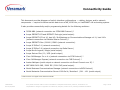
Connectivity Guide
This document provides diagrams of switch interface configurations — cabling, devices, and/or network
components — required to deliver switch data to an eCAS, eCAS Lite, or VeraSMART call accounting system.
It also provides connectivity and/or programming details for the following switches:
3COM NBX (network connection via 3COM NBX Protocol) *
Avaya DEFINITY G3 and DEFINITY ProLogix (serial output)
Avaya DEFINITY G3 rel 10, load 43 / MultiVantage or Communications Manager rel 11, load 110+
(network connection via Reliable Session Protocol) *
Avaya DEFINITY One / S8100 / IP600 (network connection)
Avaya IP Office 3.1 (network connection)
Avaya IP Office 3.0 (network connection via Delta Server)
Avaya Merlin Legend / Magix (serial output)
Avaya Partner Plus / II / ACS (serial output)
Cisco CallManager 3.x or 4.x (network connection via CCM Protocol) *
Cisco CallManager Express (network connection via CME Protocol) *
Aastra NeXspan (serial output or network connection via Direct Connect over IP) *
NEC NEAX 2400 IMS / 2000 IPS / 2000 IVS (serial output)
Nortel Business Communications Manager (network connection via BCM Protocol)
Nortel Networks Communication Server 1000 Rel 4 / Meridian 1 / SL1 - X11 (serial output)
* eCAS Lite does not support these collection methods.
70M00453D
Rev 04/12/2006
Every effort has been made to ensure information is complete and accurate; however, Veramark is not
responsible for changes in equipment or software by 3rd party vendors or for providing outdated information.
Page 1 of 29
Table of Contents
Switch Connectivity (Generic)...................................................................................................................... 3
Direct Connect ................................................................................................................................. 4
Dial-up Solutions .............................................................................................................................. 6
Network Solutions............................................................................................................................. 7
3COM NBX (Network Connection)................................................................................................................. 8
Avaya Switches ......................................................................................................................................... 9
DEFINITY G3 or DEFINITY ProLogix (Serial Output - Direct Connect) ...................................................... 10
DEFINITY G3 / MultiVantage / Communications Manager / S8300, S8500, S8700 (Reliable Session Protocol)13
DEFINITY One / S8100 / IP600 (Network Connection).......................................................................... 14
IP Office 3.1 or Greater (Network Connection) .................................................................................... 15
IP Office 3.0 (Network Connection via Delta Server) ............................................................................ 16
Merlin Legend/Magix or Partner Plus/II/ACS (Serial Output).................................................................. 18
Cisco Switches ........................................................................................................................................ 23
CallManager 3.x or 4.x (Network Connection via CCM Protocol) ............................................................. 23
CallManager Express (Network Connection via CCM Protocol) ................................................................ 24
Aastra NeXspan (Serial or Network Connection) ........................................................................................... 25
NEC NEAX 2400 IMS / 2000 IPS / 2000 IVS (Direct Connections) ................................................................... 27
Nortel Switches ....................................................................................................................................... 28
Business Communications Manager (Network Connection) .................................................................... 28
Commnication Server 1000 Rel 4 / Meridian 1 / SL1-X11 (Serial Connection) .......................................... 29
70M00453D
Rev 04/12/2006
Every effort has been made to ensure information is complete and accurate; however, Veramark is not
responsible for changes in equipment or software by 3rd party vendors or for providing outdated information.
Page 2 of 29
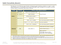
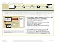
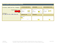
Switch Connectivity (Generic)
The diagrams in the following pages illustrate solutions for switch interfaces, whether in a single- or multiswitch environment. You can start from the type of CDR/SMDR output available from the switch, and then
consider distance and possible data transfer methods.
Output
Distance
Up to 50 ft
50 - 5000 ft
Device / Call Collection Method
None or PSU (as buffer box)
Signal boosters
Direct Connect
Remote direct connect (*)
Serial
Over 5000 ft
Dial-up PSU
eCAS / Lite + modem
PSU III — or — PSU II + MSS-100
eCAS / Lite + LAN/WAN
PollComm Remote
Call Accounting System (Modem)
PollComm Network
Call Accounting System (Network)
Collect from file (local or remote)
Network
N/A
LAN / WAN (**)
Direct Connect over IP
Other protocols:
3COM NBX, Avaya IP Office,
Nortel BCM, Cisco CallManager
70M00453D
Rev 04/12/2006
(
*)
(
**) Depends on switch tool for CDR/SMDR delivery. Supported interfaces: 3COM NBX, Avaya DEFINITY RSP, IP Office SMDR (Delta Server),
DEFINITY One/IP600/S8100; Nortel BCM; Cisco CallManager; Aastra NeXspan.
Remote direct connect is a variant of a "Direct Connect" in a multi-switch environment — where users have arranged with their Telcos
and/or facility engineers to bring all switch output to an RS-232 interface within 50 ft of the eCAS Server.
Every effort has been made to ensure information is complete and accurate; however, Veramark is not
responsible for changes in equipment or software by 3rd party vendors or for providing outdated information.
Page 3 of 29
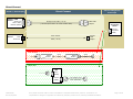
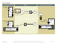
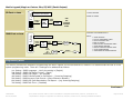
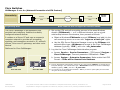
Direct Connect
Switch / CDR
Source Serial Port
DCE or DTE*
RS232C (DB25)
Call Accounting Server
Serial Input
Direct Connect
Switch w/ Serial Output
Straight serial cable (≤ 50-ft)
M
(* If serial port is DTE: use a null modem cable)
F
DB25-DB9
adapter
M-F
Call
Accounting
Server
COM port
DTE RS232
(DB9M)
Switch / CDR
Source
RJ45
Serial Port
RJ45 modular
F
cable (≤ 50-ft)
modular
-DB9
adapter
Over 50 feet:
Signal
Booster
RJ45
Signal
Booster
cable
serial
cable
F
Buffer box:
PSU
DTE in
(DB9M)
DCE out
(DB9F)
70M00453D
Rev 04/12/2006
6-ft straight serial
M
cable (DB9-DB9)
F
Every effort has been made to ensure information is complete and accurate; however, Veramark is not
responsible for changes in equipment or software by 3rd party vendors or for providing outdated information.
Page 4 of 29
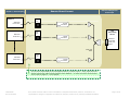
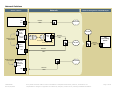
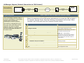
Switch 1
Wall field
house wire
Switch 2
Wall field
house wire
Call Accounting Server
Serial Input
Remote Direct Connect
Switch w/ Serial Output
Ext.
Loc.
Signal
Converter
Call
Accounting
Server
Ext.
Loc.
Signal
Converter
Softwarecontrolled
multi-port
board
multi-port
cable
Switch n
Wall field
house wire
Ext.
Loc.
Signal
Converter
It is the user's responsibility to have arranged the delivery of switch output — wiring, signal converter
devices, phone lines, cables, gender changes, and/or adapters — to within 50 ft of the call accounting
server. Refer to pages 10 - 13 for samples.
70M00453D
Rev 04/12/2006
Every effort has been made to ensure information is complete and accurate; however, Veramark is not
responsible for changes in equipment or software by 3rd party vendors or for providing outdated information.
Page 5 of 29
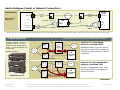
Dial-up Solutions
Dial-up
Device Connected to Switch
Direct connect
from switch
Call Accounting System Modem Input
PSU
DTE in
(DB9M)
Modem cable
from PSU kit
DCE out
(DB9F)
M
F
Phone
Modem
cord
-or-
Wall
Phone
Lines
Phone
Lines
Phone
Modem
port
cord
Wall
Direct connect
from switch
Call
Accounting
Server
Phone
cord
eCAS Lite
COM port
DTE RS232
(DB9M)
Wall
Modem /
COM port
Phone
Lines
Phone
Modem /
COM port
cord
modem
Modem
M
cable
F
modem
F
70M00453D
Rev 04/12/2006
cable
M
Modem
Every effort has been made to ensure information is complete and accurate; however, Veramark is not
responsible for changes in equipment or software by 3rd party vendors or for providing outdated information.
Page 6 of 29
Network Solutions
Network
Switch / Device
Call Accounting Server LAN/WAN Input
Switch / CDR Source
LAN
Port
Net.
network
LAN/WAN
cable
PSU II
LAN/WAN
DTE in
(DB9M)
Direct connect
from switch
DCE out
(DB9F)
PSU III
M-F
M
F
MSS
-100
Network
cable
Net.
6-ft serial cable & adapter
from MSS-100 kit
LAN/WAN
Net.
network
cable
DTE in
(DB9M)
NIC
Call
Accounting
Server
NIC
Network
cable
Direct connect
from switch
Net.
eCAS Lite
LAN/WAN
COM port
DTE RS232
(DB9M)
NIC
70M00453D
Rev 04/12/2006
Network
cable
Every effort has been made to ensure information is complete and accurate; however, Veramark is not
responsible for changes in equipment or software by 3rd party vendors or for providing outdated information.
Page 7 of 29
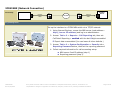
3COM NBX (Network Connection)
Connectivity
Switch
network
cable
Net.
Net.
LAN/WAN
network
Call Acc.
Server
cable
Programming Notes
Set up the interface to a 3COM NBX switch via a TCP/IP network:
1. Using Internet Explorer, access the NBX server (web address =
http://server IP address) and log in as administrator.
2. Access: Tab to it > Reports > Call Reporting tab, then set:
Call Detail Reporting = enabled with the last 0 digits scrambled
Export data unscrambled (You can leave all other defaults.)
3. Access: Tab to it > System Configuration > Security tab >
Reporting Password button, then set the reporting password.
4. Collect required information for call accounting setup:
NBX server fixed IP address (step 1)
Reporting password (step 3)
70M00453D
Rev 04/12/2006
Every effort has been made to ensure information is complete and accurate; however, Veramark is not
responsible for changes in equipment or software by 3rd party vendors or for providing outdated information.
Page 8 of 29
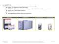
Avaya Switches
This section details connectivity and interface preparation for the following switches:
DEFINITY G3 or DEFINITY ProLogix (serial output)
DEFINITY G3 / MultiVantage / Communications Manager / S8300, S8500, S8700 (Reliable Session Protocol)
DEFINITY One / IP600 (network connection)
IP Office (network connection)
Merlin Legend/Magix or Partner Plus/II/ACS (serial output)
DEFINITY G3
70M00453D
Rev 04/12/2006
DEFINITY ProLogix
Partner Plus/II/ACS
Every effort has been made to ensure information is complete and accurate; however, Veramark is not
responsible for changes in equipment or software by 3rd party vendors or for providing outdated information.
Merlin Legend/Magix
Page 9 of 29
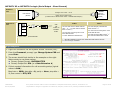
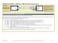
DEFINITY G3 or DEFINITY ProLogix (Serial Output - Direct Connect)
50 Feet or
Less
Switch serial port
DCE RS232C
(DB25F)
5000 Feet or
Less
D
E
F
I
N
I
T
Y
DIG I/F
2W/4W
DB25 male-to-DB9 female
(or DB25 male-to-DB25 female cable + DB25M-DB9F adapter)
2-Wire
X-H
103A
D8W
PROC
TN778
X=WALL FIELD
Call Acc.
Server
COM port
DTE RS232
(DB9M)
Straight serial cable ≤ 50-ft
DataModule
CPE
OR
COM 3-10
ROCKET
PORT
H=HOUSE WIRE
106-706-948 CP DGTL NTWK TN2181
16PT -- or -- 107-582-728 CP TN2224
DGTL LN 24PT (*)
105-164-818 Connecting Block 103A
CAT3 INFO OUTLET
113-959 MOD DATA 8400B PLUS
(
(
4-Wire
102-909 DIGITAL LINE CIRCUIT
CARD TN754C (**)
105-164-818 Connecting Block 103A
CAT3 INFO OUTLET
105-558-050 DATA MOD 7400A (**)
405-509-852 PWR SUPPLY 7400A
*) NETCON CHANNEL provided with TN798 with PPN Cabinet PE Code.
**) Item no longer orderable.
Programming Notes
1. Login into the switch via the System Access Terminal (SAT).
2. From the Command: prompt, type Change System CDR and
press Enter.
3. The screen should look similar to the example on the right.
Make certain to use these values:
Primary Output Format: UNFORMATTED
Primary Output Ext: EIA (or a Data Extension #)
4. Collect required information for call accounting setup (typical
values in bold):
Baud rate = 9600; data bits = 8; parity = None; stop bits =
1; flow control = DTR/RTS
Continued...
70M00453D
Rev 04/12/2006
Every effort has been made to ensure information is complete and accurate; however, Veramark is not
responsible for changes in equipment or software by 3rd party vendors or for providing outdated information.
Page 10 of 29
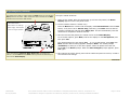
7400A Data Module
Programming Notes (continued)
The 7400A has a small p/c board which has DCE printed on one side and
DTE printed on the other. Make certain the card is inserted so the DCE
side faces the front of the data module.
7400A Data Module *
Set up the 7400A as follows:
1. Power up the 7400A. After the initial power-up self-test has passed, the Home
Display appears on the front panel screen.
2. Set the interface mode to "answer only":
Part number: 105-558-050
Power supply: 405-509-852
Press the Next button 3 times until the display reads Set Interface? Press the Yes
button, verify this is set to Answer Only (otherwise, press Next until the desired
interface is displayed) and then press Enter/Yes. This will automatically reset the
7400A and it will perform another self-test.
* Item no longer orderable.
3. After this self-test has passed, the 7400A returns to the Home Display.
To set further options, press Next, wait for the display to read Set Options?, and
then press Yes.
The 7400A prompts for each option (Set __?). To set that option, press Yes, then
Next until the desired setting appears, and press Enter. The 7400A prompts
(Continue?) to allow you to set other options. When all options have been set,
press Yes to the Done? prompt. When the Save Changes? prompt appears, press
Yes again.
Front panel buttons (Next/No, Back, Enter/Yes) are used to set
options. Use the Next and the Back buttons pressed simultaneously to
return to the Home Display.
4. After options have been saved, power off the 7400A and power it back on, so that it
can read the new settings.
Continued...
70M00453D
Rev 04/12/2006
Every effort has been made to ensure information is complete and accurate; however, Veramark is not
responsible for changes in equipment or software by 3rd party vendors or for providing outdated information.
Page 11 of 29
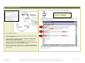
8400B Plus Data Module
Programming Notes (continued)
4. One at a time, enter the following commands (each responds OK):
8400B Plus Data Module
Part number: 113959
AT&F
ATS0=1
ATS24=1
AT&W0
AT&W1
AT&V
Alternate entry method:
AT&FS0S24=1&W0&W1&V
The data reported should look like the following window. Verify the two options you just
changed in all three profiles:
Set up the 8400B as follows:
1. Connect the 8400B to a configurator PC (COM1), as shown above. Power
up the 8400B and the PC.
2. At the PC, access HyperTerminal (Start > Programs > Accessories >
HyperTerminal > HyperTerminal).
If you had established an 8400B session before, click on its icon and
proceed to step 3; otherwise, type 8400B for a new session, connect using
Direct to Com 1, then click OK at the port settings.
3. When the HyperTerminal window appears, type AT and press Enter. The
8400B responds with OK (otherwise, check your power & data connections
and try again).
70M00453D
Rev 04/12/2006
5. Close the HyperTerminal window, confirm that you want to disconnect and exit. If this was
the first time you configured an 8400B, you will be prompted to save the session (click
Yes). Disconnect PC.
Every effort has been made to ensure information is complete and accurate; however, Veramark is not
responsible for changes in equipment or software by 3rd party vendors or for providing outdated information.
Page 12 of 29
DEFINITY G3 / MultiVantage / Communications Manager / S8300, S8500, S8700 (Reliable Session Protocol)
Connectivity
Switch
network
Net.
Net.
LAN/WAN
cable
Programming Notes
network
Call Acc.
Server
cable
NOTE: eCAS Lite does not support this collection method.
The switch software must be updated to these versions:
-
(MultiVantage or Communications Manager) release 11, load 110 or higher
(Other) release 10, load 43 or higher
Contact the Avaya Hotline at 1 (800) 242-2121 if the switch does not meet these requirements.
IP Node
Names
Add node names and IP addresses for the switch (the "local" node) and the call accounting server (the "remote" node).
IP Interfaces
Set up the IP Interface:
If type = C-LAN, add the node name for the switch, the slot where the board resides, its gateway address, and subnet mask.
If type = procr, add the node name for the switch, its IP address, and subnet mask.
IP Services
Set up IP services for service type = CDR1:
Local node = node name for the switch
Remote node = node name for the eCAS server (leave remote port = 9000 — default)
Reliable Protocol = y (leave other defaults)
CDR System
Parameters
Set up the CDR System Parameters:
Primary Output Format = unformatted
Primary Output Endpoint = CDR1 (leave other defaults)
At some point, verify network connectivity — i.e. the switch should be able to "ping" the eCAS server and vice-versa. This is done from a DOS
command prompt or Start > Run from one machine and entering ping xxx.xxx.xxx.xxx (IP address of the other machine). A response verifies
connectivity.
70M00453D
Rev 04/12/2006
Every effort has been made to ensure information is complete and accurate; however, Veramark is not
responsible for changes in equipment or software by 3rd party vendors or for providing outdated information.
Page 13 of 29
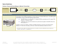
DEFINITY One / S8100 / IP600 (Network Connection)
Connectivity
Switch
network
cable
Net.
Net.
LAN/WAN
network
Call Acc.
Server
cable
Programming Notes
By default, these switches have enabled CDR output to a file named
"\LucentData\CDR\cas.in" in the switch server. Preparation
involves making it accessible to the call accounting system.
1. Set up the switch and call accounting servers in the same
Windows domain — or if in different domains, set up a trust
relationship between the domains, then proceed as follows:
a. Obtain a Windows domain account (for example, “CASusr”)
with a password (for example, “CASpsw”) that never expires.
b. At the switch server, share the folder that contains CDR data
(\LucentData\CDR) with the above user (CASusr).
For example, right-click the \LucentData\CDR folder, select
Sharing. Add "CASusr" with full rights (you can remove
"Everyone" from the list).
Avaya IP600 Server with "Softphone"
3. Collect information for call accounting setup:
Domain name & user account (from step 1a)
Collection file name & path (from step 1b — for example =
\\SwitchServerName\LucentData\CDR\cas.in)
70M00453D
Rev 04/12/2006
Every effort has been made to ensure information is complete and accurate; however, Veramark is not
responsible for changes in equipment or software by 3rd party vendors or for providing outdated information.
Page 14 of 29
IP Office 3.1 or Greater (Network Connection)
Connectivity
Switch
network
Net.
Net.
cable
LAN/WAN
network
Call Acc.
Server
cable
Programming Notes
IP Office 3.1 (or greater) includes a "CDR" feature, whereby control units can be configured to send a detailed record of each
completed call to the call accounting server. On the call accounting server side, a CDR collector tool sorts the output from
each IP Office site into its own file, which is then processed via the "collect from file (local)" call collection method.
Set up the control unit from its IP Office Manager PC:
Control
Unit
IP Office
3.1 &
greater
CDR
Call
Accounting
Server
LAN/WAN
IP Office
Manager
PC
a. Access: Programs > IP Office > Manager (password) > File > Open
> IP Office control unit (password) > system name.
b. Open the CDR tab, set these values, and then click OK:
IP Address = <call accounting server>
IP Port = 4221
Maximum CDRs to keep on communications failure = 500
Use UDP = no (leave box unchecked)
Enable CDRs = yes (check
box)
Enable intra-switch CDRs (optional, to report internal calls)
Record format = Unformatted
Date format = Month\Day
Record options = Normal
c. Open the System tab, set these values, and then click OK:
NOTE: Multiple control units from different sites can be set to output
CDR to the call accounting server in this manner. The call accounting
application includes an IP Office Configuration tool to receive and sort
out the output from each site.
70M00453D
Rev 04/12/2006
Time Server IP Address = <IP Office Manager PC>
Time Offset (hours) = ± hours from site of control unit
d. Access: File > Close and confirm saving the configuration. When
prompted, select Sending Config to = Immediately and click OK
Every effort has been made to ensure information is complete and accurate; however, Veramark is not
responsible for changes in equipment or software by 3rd party vendors or for providing outdated information.
Page 15 of 29
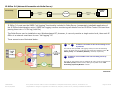
IP Office 3.0 (Network Connection via Delta Server)
Connectivity
Switch
network
cable
Net.
Net.
LAN/WAN
network
Call Acc.
Server
cable
Programming Notes
IP Office 3.0 must use the SMDR "call logging" functionality included in Delta Server (a separately installable application of
the IP Office Administration suite). SMDR call logging involves monitoring call details from an IP Office Control Unit and then
placing them into a *.CSV log (local file).
The Delta Server can be installed on any Windows-based PC; however, it can only monitor a single control unit, thus each IP
Office in a network must have its own "call logging" PC.
Three scenarios are illustrated below.
#1
and
#2
IP Office is accessible to the call accounting server
by network.
The first site sets up SMDR "call logging" locally from the call accounting
server; all others from an on-site PC. Call records are collected via the "IP
Office (Local)" and "IP Office (Remote)" methods, respectively.
#3
IP Office is not accessible to the call accounting server by
network.
Site sets up "call logging" from an eCAS/Lite PC. Call records are collected via
"IP Office (Local)" and then saved, waiting to be polled via the "Call
Accounting System by Modem" method.
Continued…
70M00453D
Rev 04/12/2006
Every effort has been made to ensure information is complete and accurate; however, Veramark is not
responsible for changes in equipment or software by 3rd party vendors or for providing outdated information.
Page 16 of 29
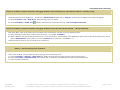
Programming Notes (Continued)
Scenario #1: IP Office is network-accessible; call logging enabled in call accounting server. Call collection method = “IP Office (Local)”
1.
Log into call accounting sever as a local administrator, then create a folder to collect output for this site — for example, C:\IPoffice.
2.
Install Delta Server from the IP Office CD — browse to its \CBC\Delta Server folder and run setup.exe. Connect to the IP Office site and enable "call logging":
a. Access: Programs > CCC > Delta Server. Select the control unit to be polled.
b. Access Event Viewer > SMDR. Mark
checkbox and then browse to the folder from step 1. Do not change the file name.
Scenario #2: IP Office is network-accessible; call logging enabled in remote PC. Call collection method = “IP Office (Remote)”
1.
Make the IP Office output in the remote PC fully accessible to the call accounting. This may involve the following actions:
a. At the remote PC, create a folder to collect output for this site — for example, C:\IPoffice.
b. Obtain a Windows user account that has these features: (a) On the remote PC: give full control to the SMDR output folder and (b) on the call accounting server: add to
the local ‘Administrators’ group (eCAS 2.5) or to the ‘VeraUsers’ group (eCAS 3.0+ / VeraSMART 2.0+).
2.
Install Delta Server and set it up in the remote PC as in scenario #1.
Scenario #3: IP Office is NOT network-accessible; eCAS and Delta Server installed in remote PC, which also has installed a call sender modem. Call collection
method = “Call Accounting System by Modem”
1.
Install eCAS at the remote IP Office site; then install and set up Delta Server as in scenario #1.
2.
At the remote eCAS PC, set up a modem for remote polling by the call accounting server:
a. Access: Processing > Switches > switch name link. Enable "Save call data for sending to another call accounting system."
b. Access: Processing > Call Sender Setup. Select modem port, its baud rate, and enable polls by another call accounting system.
c. Connect modem to a DID line.
70M00453D
Rev 04/12/2006
Every effort has been made to ensure information is complete and accurate; however, Veramark is not
responsible for changes in equipment or software by 3rd party vendors or for providing outdated information.
Page 17 of 29
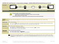
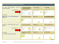
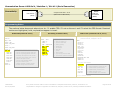
Merlin Legend/Magix or Partner Plus/II/ACS (Serial Output)
Merlin
Processor
50 Feet or Less
SMDR
1-355AF ADAPTER
Or Partner Plus/II/ACS
2-D8W-87 CORDS
SHORT
CORD
Z200A
EMI
FILTER
LONG
CORD
CPE
OR
COM 3-6
ROCKET
PORT
355AF
108404641 ADU INTERFACE KIT
Merlin
Processor
2000 Feet or Less
SMDR
PARTS:
Or Partner Plus/II/ACS
SHORT
CORD
Z200A
EMI
FILTER
LONG
CORD
CPE
COM 2
OR
COM 3-6
ROCKET PORT
355AF
ADU-F
M7U-87
D8W
ADU-F
D8AM-87
D8W
103A
103A
X-H
1-355AF ADAPTER
1-M7U-87 CROSSOVER CABLE
2-2169-004 FEMALE ADU
2-D8W-87 CORDS
1-D8AM-87 ADU CROSSOVER CABLE
1-400B2 POWER ADAPTER
1-D6AP-87 MODULAR POWER CORD
1-2012D TRANSFORMER
1-248B MODULAR POWER ADAPTER
Programming Notes
This section provides two methods of programming the Merlin Legend: the console and the PC method. It is assumed that the user is in the
system programming mode. There are 7 settings to be addressed as follows:
1st Setting:
2nd Setting:
3rd Setting:
4th Setting:
5th Setting:
6th Setting:
7th Setting:
SMDR Language – Verify the setting is (English)
SMDR Call Report Format – (Basic)
SMDR Call Length – (40 seconds)
SMDR Calls Recorded on Call Report – (Incoming Outgoing)
SMDR Account Code Format –(Home Extension Number)
SMDR UDP Calls Recorded on Call Report – (Log Incoming/Outgoing)
SMDR Talk Time – (Disabled)
Continued...
70M00453D
Rev 04/12/2006
Every effort has been made to ensure information is complete and accurate; however, Veramark is not
responsible for changes in equipment or software by 3rd party vendors or for providing outdated information.
Page 18 of 29
Merlin Legend Programming Notes (continued)
1st Setting: SMDR Language – Verify the
setting is (English)
Console Method:
PC Method:
PgUp > F6 > F3 > Select Language >
F10 > F5
1.
Go to the second screen of
the System Programming
menu and Press More
System Programming
Make a selection
System
SysRenumber
Operator
LinesTrunks
Exit
>
Extension
Options
Tables
AuxEquip
NightSrvce
4. Specify the SMDR language
SMDR Languages
Select one
English
French
Spanish
Exit
2nd Setting: SMDR Call Report Format –
(Basic)
Console Method:
1.
F7 > F8 > F1 > F10 > F5 > F5
Select Language
System Programming
Make a selection
Labeling
Data
Print
Cntr-Prg
Exit
Select the Options Menu
>
Extension
Options
Tables
AuxEquip
NightSrvce
Specify Format for SMDR
reports
3.
>
Language
5. Select Enter
Select SMDR
Language:
Make a selection
System Lang
Extensions
SMDR
Printer
Exit
6. For Merlin Legend select Exit
For Merlin Magix select Back
Enter
Enter
System Programming
Make a selection
System
SysRenumber
Operator
LinesTrunks
Exit
4.
PC Method:
2.
2. Select SMDR
Options
Make a selection
Transfer
CampOn
CallParkRtn
Delay Ring
Exit
Exit
3. Select Call Report Format
>
Callback
Ext. Status
SMDR
Inside Dial
Reminder Srv
5. Select Enter
Station Message Record
Make a selection
Format
Auth Code
Call Length
Talk Time
Call Report
UDP
New Page
Exit
6. Select Exit twice
SMDR Format
Select one
Basic SMDR
ISDN SMDR
Exit
Enter
Enter
Exit
Continued...
70M00453D
Rev 04/12/2006
Every effort has been made to ensure information is complete and accurate; however, Veramark is not
responsible for changes in equipment or software by 3rd party vendors or for providing outdated information.
Page 19 of 29
Merlin Legend Programming Notes (continued)
3rd Setting: SMDR Call Length – (40
seconds)
Console Method:
1.
System Programming
Make a selection
System
SysRenumber
Operator
LinesTrunks
Exit
4.
PC Method:
F7 > F8 > F2 > Alt + P > Verify # of
Seconds > F10 > F5 > F5
Select the Options Menu
>
Extension
Options
Tables
AuxEquip
NightSrvce
Verify setting (40)
Console Method:
PC Method:
>
Callback
Ext. Status
SMDR
Inside Dial
Reminder Srv
5. Select Enter
Station Message Record
Make a selection
Format
Auth Code
Call Length
Talk Time
Call Report
UDP
New Page
Exit
6. Select Exit twice
(0-255)
1.
Enter
Enter
Select the Options Menu
System Programming
Make a selection
System
SysRenumber
Operator
LinesTrunks
Exit
4.
F7 > F8 > F3 > F1 > F10 > F5 > F5
Options
Make a selection
Transfer
CampOn
CallParkRtn
Delay Ring
Exit
3. Select Call Report Format
SMDR minimum time
040
Backspace
Exit
4th Setting: SMDR Calls Recorded on Call
Report – (Incoming Outgoing)
2. Select SMDR
>
Extension
Options
Tables
AuxEquip
NightSrvce
Verify In/Out
2. Select SMDR
Options
Make a selection
Transfer
CampOn
CallParkRtn
Delay Ring
Exit
Exit
3. Select Call Report Format
>
Callback
Ext. Status
SMDR
Inside Dial
Reminder Srv
5. Select Enter
Station Message Record
Make a selection
Format
Auth Code
Call Length
Talk Time
Call Report
UDP
New Page
Exit
6. Select Exit twice
SMDR Call Report
Select one
In/Out
Out Only
Exit
Enter
Enter
Exit
Continued...
70M00453D
Rev 04/12/2006
Every effort has been made to ensure information is complete and accurate; however, Veramark is not
responsible for changes in equipment or software by 3rd party vendors or for providing outdated information.
Page 20 of 29
Merlin Legend Programming Notes (continued)
5th Setting: SMDR Account Code Format –
(Home Extension Number)
Console Method:
PC Method:
1.
Select the Options Menu
System Programming
Make a selection
System
SysRenumber
Operator
LinesTrunks
Exit
4.
F7 > F8 > F6 > F1 > F10 > F5 > F5
>
Extension
Options
Tables
AuxEquip
NightSrvce
Specify whether the home
ext. or the auth code is
recorded
2. Select SMDR
Options
Make a selection
Transfer
CampOn
CallParkRtn
Delay Ring
Exit
3. Select Call Report Format
>
Callback
Ext. Status
SMDR
Inside Dial
Reminder Srv
5. Select Enter
Station Message Record
Make a selection
Format
Auth Code
Call Length
Talk Time
Call Report
UDP
New Page
Exit
6. Select Exit twice
Account Code Format
Select one
Home Extension Number
Authorization Code
Exit
6th Setting: SMDR UDP Calls Recorded on
Call Report – (Log Incoming/Outgoing)
Console Method:
PC Method:
1.
4.
F7 > F8 > F8 > F1 > F10 > F5 > F5
Select the Options Menu
System Programming
Make a selection
System
SysRenumber
Operator
LinesTrunks
Exit
Enter
Enter
>
Extension
Options
Tables
AuxEquip
NightSrvce
Verify SMDR information is
recorded for both incoming
and outgoing UDP calls
2. Select SMDR
Options
Make a selection
Transfer
CampOn
CallParkRtn
Delay Ring
Exit
Exit
3. Select Call Report Format
>
Callback
Ext. Status
SMDR
Inside Dial
Reminder Srv
5. Select Enter
Station Message Record
Make a selection
Format
Auth Code
Call Length
Talk Time
Call Report
UDP
New Page
Exit
6. Select Exit twice
SMDR Report – UDP Calls
Select one
Log Incoming/Outgoing
Log None
Exit
Enter
Enter
Exit
Continued...
70M00453D
Rev 04/12/2006
Every effort has been made to ensure information is complete and accurate; however, Veramark is not
responsible for changes in equipment or software by 3rd party vendors or for providing outdated information.
Page 21 of 29
Merlin Legend Programming Notes (continued)
7th Setting: SMDR Talk Time – (Disabled)
Console Method:
PC Method:
F7 > F8 > F7 > F1 > F10 > F5 > F5
1.
Select the Options Menu
System Programming
Make a selection
System
SysRenumber
Operator
LinesTrunks
Exit
>
Extension
Options
Tables
AuxEquip
NightSrvce
4. Enable Talk Time
2. Select SMDR
Options
Make a selection
Transfer
CampOn
CallParkRtn
Delay Ring
Exit
3. Select Call Report Format
>
Callback
Ext. Status
SMDR
Inside Dial
Reminder Srv
5. Select Enter
Station Message Record
Make a selection
Format
Auth Code
Call Length
Talk Time
Call Report
UDP
New Page
Exit
6. Select Exit twice
SMDR Format
Select one
Enable
Talk Time
Exit
70M00453D
Rev 04/12/2006
Enter
Enter
Every effort has been made to ensure information is complete and accurate; however, Veramark is not
responsible for changes in equipment or software by 3rd party vendors or for providing outdated information.
Exit
Page 22 of 29
Cisco Switches
CallManager 3.x or 4.x (Network Connection via CCM Protocol)
Connectivity
Switch
network
cable
Programming Notes
Net.
Net.
LAN/WAN
network
Call Acc.
Server
cable
NOTE: eCAS Lite does not support this collection method.
The Cisco CallManager is an application that
provides basic telephony features to suitably
configured network devices.
It resides on a Server PC and uses a company's
computer network to provide call processing,
signaling, and connection services to IP- and softphones, Voice-over-IP gateways, and other voice
devices.
Platforms for Cisco CallManager:
1. Set up the CCM and call accounting servers in the same Windows
domain (CCMdomain) — or if in different domains, set up a trust
relationship between the domains, then proceed as follows: (1)
a. Obtain a Windows CCMdomain account (CCMuser) and add it in the
call accounting server as a user with "Logon as a batch job" rights.
a. Use the SQL Server Enterprise Manager to set up the CCMuser with
authentication type = Windows and access to the Cisco CallManager
database (typically, "CDR"), with role = db_datareader.
2. Log into the Cisco CallManager Administration program.
a. Access: Service > Service Parameters > [CCM server] Services >
Cisco CallManager. Then set parameter CdrEnabled = True (2)
b. Access: System > Enterprise Parameters. Make certain that CDR
Format = CDRs will be inserted into Database.
(1) If using "Mixed Mode" authentication, simply set up a user account (CCMuser) via the SQL Server
Enterprise Manager with authentication type = Mixed Mode and access to the Cisco CallManager
database (typically, "CDR"), with role = db_datareader.
Cisco ICS 7750
70M00453D
Rev 04/12/2006
Cisco MCS 7800
(2) You can also set up Call Diagnostics Enabled = True if you wish to report Quality of Service data
using the call accounting system.
Every effort has been made to ensure information is complete and accurate; however, Veramark is not
responsible for changes in equipment or software by 3rd party vendors or for providing outdated information.
Page 23 of 29
CallManager Express (Network Connection via CCM Protocol)
Connectivity
CME Router
network
Net.
Net.
LAN/WAN
cable
Programming Notes
cable
NOTE: eCAS Lite does not support this collection method.
Cisco CallManager Express (CME) is
a solution embedded in Cisco IOS®
software that provides call
processing for Cisco IP phones.
This solution is designed for up to
240 users who need data-routing
capability and want to enable
telephony features, including voice
mail and automated attendant on
the same router.
70M00453D
Rev 04/12/2006
Call Acc.
Server
network
Obtain the assistance of the CME system administrator to access the CME as 'admin' —
for example, through Telnet. Enter the following commands at each prompt. When
complete, quit Telnet and close the Command Prompt window.
#
CME Setup Commands
Purpose
1
enable
Enters EXEC mode (enter password)
2
configure terminal
Enters global configuration mode
3
aaa new-model
4
aaa accounting connection h323 start-stop group radius
Enables AAA for call collection, then exits
the gateway accounting mode
5
gw-accounting aaa
6
no suppress
7
exit
NOTE: AAA = Authentication,
authorization, and accounting. Network
security services through which access
control can be set on a Cisco router or
access server.
8
radius-server host <CME hostname or IP address> auth-port
<number> acct-port <number>
Specifies the CME name and ports used for
collecting call data
9
radius-server vsa send accounting
Enables sending call data
10
radius-server key <password>
Sets the password to connect to the CME
11
exit
Exits configuration mode
Every effort has been made to ensure information is complete and accurate; however, Veramark is not
responsible for changes in equipment or software by 3rd party vendors or for providing outdated information.
Page 24 of 29
Aastra NeXspan (Serial or Network Connection)
Connectivity
network
LAN port
Billing Node or
Main Server
Net.
Net.
LAN/WAN
cable
— or —
Call Acc.
Server
cable
LAN port
— or —
PSU
RJ45-DB9F adapter
DTE in
(DB9M)
RJ45
Printer port
(serial *)
network
COM
Port
RJ45-DB9F
adapter
cable
* Serial connection is not recommended because NeXspan does not buffer CDRs when set for serial output (any break in transmissions could result in the loss of call records).
Programming Notes
NOTE: eCAS Lite does not support the network collection method.
An Aastra telecom network of
NeXspan switches — a main
billing server & multiple billing
nodes — can be distributed over
a wide area.
NeXspan Platforms:
Node
1
PSTN
PSTN
Main
Server
CDR
CDR
Call
Accounting
Server
Node
2
Scenario #1. Distributed
network, combined CDR
Networked sites; the main server
polls each node & then outputs all
CDR via a single network or serial
connection.
LAN/WAN
Server
2
LAN/WAN
Server
1
PSTN
PSTN
Server
3
NeXspan C, S, or L
CDR
Call
Accounting
Server
Scenario #2. Non-distributed
network, individual CDR
Multiple, independent sites; each
one outputs CDR via a network or
serial connection.
Continued…
70M00453D
Rev 04/12/2006
Every effort has been made to ensure information is complete and accurate; however, Veramark is not
responsible for changes in equipment or software by 3rd party vendors or for providing outdated information.
Page 25 of 29
Aastra NeXspan Programming Notes (continued)
Obtain the assistance of the network / switch administrator for the following tasks:
1. (Scenario #1) Program the main server to poll each node for CDR.
TECHNICAL NOTE: this is done by having the 'MUFACT' service at the server contact the 'KITAXE' service at each node to collect CDR.
2. (All scenarios) Program main server and nodes for CDR output.
a. Use ADMINISTRATION PARAMETERS to set up the following:
— STEP BY STEP DEFINITION = PAD LINK for a network connection or OUTPUT CHANNEL for a serial connection
— OUTPUT FORMAT = EXTENDED FORMAT V3 or V4
(1)
(2)
— CALL TYPE = INCOM. AND OUTGO.
— DELETE RECORDS WITHOUT CHARGING = NO
b. Use TCP-X25 ADDRESS PORT TRANSL to select the CDR output port.
c. Use INTEGR. BUFFER MANAGEMENT - PARAMETER MANAGEMENT to set the buffer size & management mode to PERM.
CONNECTION.
3. (All scenarios) Make the physical connections:
(Network) Add the call accounting server to the Aastra network. Verify network connectivity by "pinging" the NeXspan unit from the
call accounting server (access: Start > Run > ping <unit IP address>).
(Serial) Plug an RJ45 cable to the NeXspan printer port; use an RJ45-DB9F adapter on the other end. If within 50 feet, plug the
adapter into the call accounting server COM port; remote connections require an on site Pollable Storage Unit (PSU), installed as per
its setup guide.
(1)
Network connections are recommended. If using a serial connection, skip steps 2b - 2c; instead, access TERMINAL MANAGEMENT to set PRINTER – SPEED = V24.9600.
(2)
These are the only call record formats supported in eCAS or VeraSMART.
70M00453D
Rev 04/12/2006
Every effort has been made to ensure information is complete and accurate; however, Veramark is not
responsible for changes in equipment or software by 3rd party vendors or for providing outdated information.
Page 26 of 29
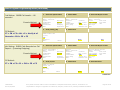
NEC NEAX 2400 IMS / 2000 IPS / 2000 IVS (Direct Connections)
Connectivity
PN-CP14
PN-CP20
via
Built-in SMDR on the
MP (Main rocessor)
RS0
-orRS1
Call Accounting
Server
RS RVS-15S CA-A (15m ~ 49.2ft)
or
RS RVS-4S CA-A (4m ~ 13.1ft)
DB25-DB9
adapter
COM port
DTE RS232
(DB9M)
Cable ends in a 25-pin female
connector and may need adapter
to fit the PC's COM port.
Distances over 50 ft require the
use of modems & an RS NORM4S CA-A cable connected to the
MP RS0 port.
Programming Notes (MP Built-in SMDR Programming)
This section outlines commands used through the CAT (Customer Administration Terminal).
It is assumed that the user is in the system-programming mode, the MP is on-line ("RUN" lamp is flashing), and all data related to the station, trunks, and
service features (such as authorization/account codes) are already programmed.
There are 7 settings to be addressed (defaults in parentheses):
1st
Setting:
CM40 - Output port & attributes (9600 baud, 8 data bits, no parity, 2 stop bits, DTR/RTS flow control)
2nd
Setting:
CM13+06 - Enable SMDR for outgoing calls to required stations (enabled, must specify stations)
3rd
Setting:
CM35+14 - Enable SMDR for outgoing calls to required trunk routes (enabled, must specify trunk routes)
4th
Setting:
CM13+05 - Enable SMDR for incoming calls to required stations (disabled)
5th
Setting:
CM35+49 - Enable SMDR for incoming calls to required trunk routes (disabled)
6th
Setting:
CM08 - If SMDR for incoming calls is enabled, specify whether it applies to all incoming calls or only to those with Account Codes
(Account Codes only)
7th
Setting:
CM08 - Include ANI/Caller ID for incoming calls (exclude)
NOTE: "Include" is required to provide SMDR for incoming calls, even if this feature is enabled by CM13+05 and CM35+49.
Consult the Feature Programming and Command manuals for the specific NEAX switch for details.
70M00453D
Rev 04/12/2006
Every effort has been made to ensure information is complete and accurate; however, Veramark is not
responsible for changes in equipment or software by 3rd party vendors or for providing outdated information.
Page 27 of 29
Nortel Switches
Business Communications Manager (Network Connection)
Connectivity
Switch
network
cable
Net.
Net.
LAN/WAN
network
Call Acc.
Server
cable
Programming Notes
The system uses a DCOM connection to collect calls from a Nortel BCM server. The BCM system
administrator must provide the following requirements:
The BCM Server is configured to (1) accept DCOM connections and (2) output CDR
reports in a Norstar format.
A Windows user account has been set up with access rights to the BCM Server for
CDR collection. (*)
BCM Server
Typically, you will not need to configure a DCOM connection in the call accounting server.
However, if it becomes necessary, the User's Guide has detailed procedures to do so.
(
70M00453D
Rev 04/12/2006
*) This account must be added on the call accounting server as a member of the local ‘Administrators’ group (eCAS 2.5) or
‘VeraUsers’ group (eCAS 3.0 / VeraSMART 2.0).
Every effort has been made to ensure information is complete and accurate; however, Veramark is not
responsible for changes in equipment or software by 3rd party vendors or for providing outdated information.
Page 28 of 29
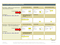
Commnication Server 1000 Rel 4 / Meridian 1 / SL1-X11 (Serial Connection)
Connectivity
Call acc.
Server
COM port
DTE RS232
(DB9M)
Switch serial port
straight serial cable ≤ 50-ft
DCE RS232C
(DB9F)
(DB9 male-to-DB9 female)
Programming Notes
The sections below document where to go to: (1) enable CDR, (2) set up the port, and (3) select the CDR format. Required
entries are highlighted, bold; explanations appear in insert.
Enable CDR (command: LD 21)
>LD 21
PT1000
>LD 22
REQ: PRT
TYPE: CDR
TYPE CDR_DATA
CUST 0
TYPE CDR_DATA
CUST 00
CDR YES
←
IMPH NO
←
OMPH NO
←
AXID YES
←
TRCR YES
←
CDPR NO
←
ECDR YES
←
PORT 2
←
CHLN 0
←
FCAF NO
←
Port Setup (command: LD 22)
enables CDR
cdr for incoming packet data call
cdr for outgoing packet data call
auxiliary ID output in cdr record
carriage return after each record
coord. dial plan record
end-to-end signaling digits
tty port used on pbx
charge account number length
forced charge account active?
ADAN
CARD
PORT
DES
BPS
BITL
STOP
PARY
FLOW
USER
XSM
TTY 2
00
2
2ND-FLOOR
1200
8
1
NONE
NO
CTY
NO
←
←
←
←
←
←
←
←
←
←
←
Port number
card it resides on
port on that card
label (option)
baud rate
bit length
stop bit
parity
flow control
type of tty port for CDR
part of the system monitor?
CDR Format (commands: LD 22; LD 17)
***** the following is part System config. for cdr
printed in LD 22; changed in LD 17.
PARM
LPIB
HPIB
500B
NCR
MGCR
CSQI
CSQO
NCPU
CFWS
PCML
ALRM
ERRM
DTRB
TMRK
125
50
200
300
NULL
020
020
1
NO
MU
YES
ERR BUG AUD
100
128
***** start CDR section
FCDR
PCDR
TPO
TSO
CLID
DUR5
NEW
NO
NO
NO
NO
NO
←
←
←
←
←
←
for use with CDR format #511
gives processor priority to cdr
enable traffic period option
enable trunk period option
calling line ID in cdr
round duration to 5 seconds
******* end cdr section
70M00453D
Rev 04/12/2006
Every effort has been made to ensure information is complete and accurate; however, Veramark is not
responsible for changes in equipment or software by 3rd party vendors or for providing outdated information.
Page 29 of 29