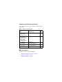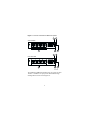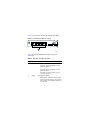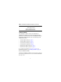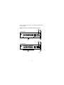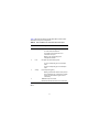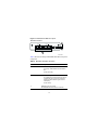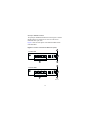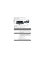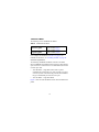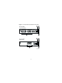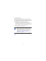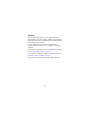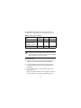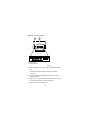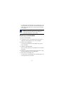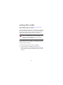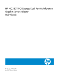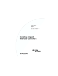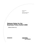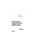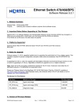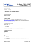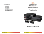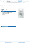
1
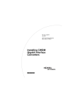
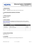
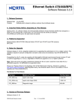
Part No. 302403-G
July 2001
4401 Great America Parkway
Santa Clara, CA 95054
Installing Media
Dependent Adapters
(MDAs)
*302403-G*
Copyright © 2001 Nortel Networks
All rights reserved. July 2001.
The information in this document is subject to change without notice. The
statements, configurations, technical data, and recommendations in this document
are believed to be accurate and reliable, but are presented without express or
implied warranty. Users must take full responsibility for their applications of any
products specified in this document. The information in this document is
proprietary to Nortel Networks Inc.
Trademarks
Nortel Networks, the Nortel Networks logo, Passport, BayStack, Business Policy
Switch 2000, and the Globemark and are trademarks of Nortel Networks.
Adobe and Acrobat Reader are trademarks of Adobe Systems Incorporated.
Statement of conditions
In the interest of improving internal design, operational function, and/or reliability,
Nortel Networks Inc. reserves the right to make changes to the products described
in this document without notice.
Nortel Networks Inc. does not assume any liability that may occur due to the use or
application of the product(s) or circuit layout(s) described herein.
EMI Compliance
Meets requirements of:
FCC Part 15, Subparts A and B, Class A
EN55022: 1998/CISPR22:1997), Class A
General License VDE 0871, Class B
(AmtsblVfg No. 243/1991, Vfg 46/1992) VCCI Class A ITE
EN55024:1998/CISPR24:1997
Caution: Use of controls or adjustments, or performance
of procedures other than those specified herein may
result in hazardous radiation exposure.
Caution: Only qualified technicians should install this
equipment.
Place all printed circuit boards on an antistatic mat until
you are ready to install them. If you do not have an
antistatic mat, wear a discharge leash to free yourself of
static before touching any of the printed circuit boards, or
free yourself of static by touching a grounded metal
object before handling a printed circuit board.
Product Safety
Meets requirements of:
CSA 22.2 No. 950-M95/UL1950, 3rd ed.
EN60950: 1992 /A1:1993 /A2:1993 /A3:1995 /A4:
199721CFR, Chapter I
EN60825-1:1994 /A11:1996
Warning: Fiber optic equipment can emit laser or
infrared light that can injure your eyes. Never look into
an optical fiber or connector port. Always assume that
fiber optic cables are connected to a light source.
Warning: Vorsicht: Glasfaserkomponenten können
Laserlicht bzw. Infrarotlicht abstrahlen, wodurch Ihre
Augen geschädigt werden können. Schauen Sie
niemals in einen Glasfaser-LWL oder ein Anschlußteil.
Gehen Sie stets davon aus, daß das Glasfaserkabel an
eine Lichtquelle angeschlossen ist.
1
Warning: Avertissement: L’équipement à fibre
optique peut émettre des rayons laser ou infrarouges
qui risquent d’entraîner des lésions oculaires. Ne
jamais regarder dans le port d’un connecteur ou d’un
câble à fibre optique. Toujours supposer que les câbles
à fibre optique sont raccordés à une source lumineuse.
Warning: Advertencia: Los equipos de fibra óptica
pueden emitir radiaciones de láser o infrarrojas que
pueden dañar los ojos. No mire nunca en el interior de
una fibra óptica ni de un puerto de conexión. Suponga
siempre que los cables de fibra óptica están conectados
a una fuente luminosa.
Warning: Avvertenza: Le apparecchiature a fibre
ottiche emettono raggi laser o infrarossi che possono
risultare dannosi per gli occhi. Non guardare mai
direttamente le fibre ottiche o le porte di collegamento.
Tenere in considerazione il fatto che i cavi a fibre
ottiche sono collegati a una sorgente luminosa.
2
Introduction
This guide describes and provides installation instructions for
Nortel Networks* media dependent adapters (MDAs). It contains
the following topics:
•
“Supported interfaces and products,” next
•
“MDA descriptions” on page 4
•
“Installing an MDA” on page 24
•
“Replacing an installed MDA” on page 27
•
“Installing a GBIC in an MDA” on page 28
•
“Removing an Installed GBIC from an MDA” on page 29
•
“1000BASE-LX Multimode Applications” on page 30
Caution: MDAs are not hot-swappable. To avoid
damage to the switch or MDA, power down the switch or
unplug the switch module from the switch backplane
before installing or removing an MDA.
3
Supported interfaces and products
Table 1 shows the interface types used with the MDAs described
in this guide.
Table 1 MDAs and interface types
MDA
Interface Type
See
page
•
•
•
400-4TX MDA
8100-4TX MDA
BPS2000-4TX MDA
10BASE-T/100BASE-TX (UTP)
5
•
•
•
•
•
•
400-2FX MDA
8100-2FX MDA
BPS2000-2FX MDA
400-4FX MDA
8100-4FX MDA
BPS2000-4FX MDA
100BASE-FX (Fiber)
9
•
•
450-1SR MDA
450-1SX MDA
1000BASE-SX
(Shortwave gigabit fiber)
16
•
•
450-1LR MDA
450-1LX MDA
1000BASE-LX
(Longwave gigabit fiber)
19
•
450-1GBIC MDA
Gigabit Interface Converter (GBIC)
22
MDA descriptions
This section describes the following MDAs:
•
“10BASE-T/100BASE-TX MDAs” on page 5
•
“100BASE-FX MDAs” on page 9
•
“1000BASE-X MDAs” on page 16
4
•
“GBIC MDA” on page 22
10BASE-T/100BASE-TX MDAs
The 10BASE-T/100BASE-TX MDAs use four RJ-45 (8-pin
modular) connectors, configured as media dependent interfacecrossover (MDI-X) connectors. These ports connect over straight
cables to the network interface controller (NIC) card in a node or
server, similar to a conventional Ethernet repeater hub.
If you connect to another Ethernet hub or Ethernet switch, you
need a crossover cable unless an MDI connection exists on the
associated port of the attached device.
The following are the 10BASE-T/100BASE-TX MDAs.
•
400-4TX MDA, page 6
•
8100-4TX MDA, page 6
•
BPS2000-4TX MDA, page 8
For a complete list of MDAs, see Table 1 on page 4. For
installation instructions, see “Installing an MDA” on page 24.
Figure 1 shows the front panels of the 400-4TX MDA and the
8100-4TX MDA.
5
Figure 1 400-4TX and 8100-4TX MDA front panels
1
2
400-4TX MDA
100
10
F Dx
Activity
400-4TX MDA
5
4
1
3
2
8100-4TX MDA
100
10
F Dx
Activity
8100-4TX MDA
5
4
3
BS45042B
The 10BASE-T/100BASE-TX MDA ports can operate at either
10 Mb/s or 100 Mb/s. The port speed is determined through
autonegotiation with its connecting device.
6
Table 2 describes the 400-4TX and 8100-4TX MDA front-panel.
Table 2 400-4TX and 8100-4TX MDA front panel
Item
Label
Description
1
100
100BASE-TX port status LEDs (green):
On: The corresponding port is set to operate at
100 Mb/s.
Off: The link connection is bad or there is no
connection to this port.
Blinking: The corresponding port is management
disabled.
2
10
10BASE-T port status LEDs (green):
On: The corresponding port is set to operate at
10 Mb/s.
Off: The link connection is bad or there is no
connection to this port.
Blinking: The corresponding port is management
disabled.
3
F Dx
Full-duplex port status LEDs (green):
On: The corresponding port is in full-duplex mode.
Off: The corresponding port is in half-duplex
mode.
4
Activity
Port activity LEDs (green):
Blinking: Indicates the network activity level for the
corresponding port. A high level of network activity
can cause LEDs to appear to be on continuously.
5
10BASE-T/100BASE-TX RJ-45 (8-pin modular) port
connectors.
7
Figure 2 shows the front panel of the BPS2000-4TX MDA.
Figure 2 BPS2000-4TX MDA front panel
1
BPS2000-4TX MDA
2
3
9792EA
Table 3 describes the BPS2000-4TX MDA front-panel
components.
Table 3 BPS2000-4TX MDA description
Item
Label
Description
1
10/100
10BASE-T/100BASE-TX port status LEDs:
On (green): The corresponding port is set to
operate at 100 Mb/s.
On (yellow): The corresponding port is set to
operate at 10 Mb/s.
Off: The link connection is bad or there is no
connection to this port.
2
Activity
Port activity LEDs (green):
Blinking (green): Indicates the network activity
level for the corresponding port. A high level of
network activity can cause LEDs to appear to be
on continuously.
8
Table 3 BPS2000-4TX MDA description (continued)
Item
Label
Description
Off: No traffic to this port.
3
10BASE-T/100BASE-TX RJ-45
(8-pin modular) port connectors.
100BASE-FX MDAs
The 100BASE-FX MDAs conform to the IEEE 802.3u
100BASE-FX standard and can attach fiber-based 100 Mb/s
connections to Fast Ethernet devices. The 100BASE-FX MDAs
do not support single-mode fiber cable. The following are the
100BASE-FX MDAs.
•
400-2FX MDA (dual-port), page 10
•
400-4FX MDA (quad-port), page 13
•
8100-2FX MDA (dual-port), page 10
•
8100-4FX MDA (quad-port), page 13
•
BPS2000-2FX MDA (dual-port), page 12
•
BPS2000-4FX MDA (quad-port), page 15
For a complete list of MDAs, see Table 1 on page 4. For
installation instructions, see “Installing an MDA” on page 24.
Dual-port 100BASE-FX MDAs
The dual-port 100BASE-FX MDAs use two longwave 1300 nm
SC connectors to attach devices over 62.5/125 micron multimode
fiber optic cable.
9
Figure 3 shows the front panels of the 400-2FX MDA and the
8100-2FX MDA.
Figure 3 400-2FX and 8100-2FX MDA front panels
1
2
400-2FX MDA
100BASE-FX
100BASE-FX
Link
F Dx
Activity
TX
RX
TX
RX
400-2FX MDA
3
4
1
2
8100-2FX MDA
100BASE-FX
100BASE-FX
Link
F Dx
Activity
TX
RX
TX
RX
8100-2FX MDA
3
4
BS45071A
10
Table 4 describes the dual-port 400-2FX MDA and the 81002FX MDA front-panel components.
Table 4 400-2FX MDA and 8100-2FX MDA description
Item
Label
Description
1
Link
Communications link LEDs (green):
On: Valid communications link.
Off: Invalid communications link or no
connection to this port.
Blinking: The corresponding port is
management disabled.
2
F Dx
Full-duplex port status LEDs (green):
On: The corresponding port is in full-duplex
mode.
Off: The corresponding port is in half-duplex
mode.
3
Activity
Port activity LEDs (green):
Blinking: Indicates the network activity level for
the corresponding port. A high level of network
activity can cause LEDs to appear to be on
continuously.
4
100BASE-FX port connectors:
Models 400-2FX and 8100-2FX use SC connectors.
Figure 4 shows the front panel of the dual-port BPS2000-2FX
MDA.
11
Figure 4 BPS2000-2FX MDA front panel
BPS2000-2FX MDA
1
BPS2000-2FX MDA
2
3
BPS20001A
Table 5 describes the dual-port BPS2000-2FX MDA front-panel
components.
Table 5 BPS2000-2FX MDA description
Item
Label
Description
1
Link
Link status LEDs (green):
On (green): Valid 100 Mb/s communications
link.
Off: No link activity.
2
Activity
Port activity LEDs (green):
On: Indicates the network activity level for the
corresponding port. A high level of network
activity can cause LEDs to appear to be on
continuously.
Off: No activity.
3
100BASE-FX port connectors:
The BPS2000-2FX MDA uses SC connectors.
12
Quad-port 100BASE-FX MDAs
The quad-port 100BASE-FX MDAs use four longwave 1300 nm
MT-RJ connectors to attach devices over 62.5/125 micron
multimode fiber optic cable.
Figure 5 shows the front panels of the 400-4FX MDA and the
8100-4FX MDA.
Figure 5 400-4FX and 8100-4FX MDA front panels
1
400-4FX MDA
Link
2
F Dx
Activity
400-4FX MDA
3
4
1
8100-4FX MDA
Link
2
F Dx
Activity
8100-4FX MDA
3
4
BS45072A
13
Table 6 describes the 400-4FX MDA and the 8100-4FX MDA
front-panel components.
Table 6 400-4FX MDA / 8100-4FX MDA description
Item
Label
Description
1
Link
Communications link LEDs (green):
On: Valid communications link.
Off: Invalid communications link or no connection
to this port.
Blinking: The corresponding port is management
disabled.
2
F Dx
Full-duplex port status LEDs (green):
On: The corresponding port is in full-duplex mode.
Off: The corresponding port is in half-duplex
mode.
3
Activity
Port activity LEDs (green):
Blinking: Indicates the network activity level for the
corresponding port. A high level of network activity
can cause LEDs to appear to be on continuously.
4
100BASE-FX port connectors:
Models 400-4FX and 8100-4FX use MT-RJ connectors.
Figure 6 shows the front panel of the BPS2000-4FX MDA.
14
Figure 6 BPS2000-4FX MDA front panel
BPS2000-4FX MDA
1
BPS2000-4FX MDA
3
2
BPS20002A
Table 7 describes the BPS2000-4FX MDA front-panel
components.
Table 7 BPS2000-4FX MDA description
Item
Label
Description
1
Link
Link status LEDs (green):
On (green): Valid 100 Mb/s communications link.
Off: No link activity.
2
Activity
Port activity LEDs (green):
On: Indicates the network activity level for
the corresponding port. A high level of
network activity can cause LEDs to appear
to be on continuously.
Off: No activity.
3
100BASE-FX port connectors:
The BPS2000-4FX MDA uses MT-RJ connectors.
15
1000BASE-X MDAs
The following are the 1000BASE-FX MDAs.
Table 8 1000BASE-FX MDAs
Shortwave gigabit
•
•
450-1SR MDA, page 17
450-1SX MDA, page 17
Longwave gigabit
•
•
450-1LR MDA, page 20
450-1LX MDA, page 20
For a complete list of MDAs, see Table 1 on page 4. For
installation instructions, see “Installing an MDA” on page 24.
Shortwave Gigabit MDAs
The following 1000BASE-SX MDAs conform to the IEEE
802.3z 1000BASE-SX standard and use shortwave 850 nm fiber
optic connectors to connect devices over multimode (550 m/1805
ft.) fiber optic cable.
•
450-1SR MDA -- single MAC MDA with a separate
redundant Phy (backup Phy port). Only one Phy port can be
active at any time. If the active Phy port fails, the redundant
Phy port automatically becomes the active port.
•
450-1SX MDA -- single PHY MDA.
Figure 7 shows the 450-1SR MDA and the 450-1SX MDA front
panels.
16
Figure 7 450-1SR and 450-1SX MDA front panels
1
450-1SR MDA
(1-port redundant)
1000BASE-SX
2
1000BASE-SX
Link
Phy Select
Activity
TX
RX
TX
RX
450-1SR MDA
3
4
1
450-1SX MDA
(single port)
2
1000BASE-SX
Link
Phy
Activity
TX
RX
450-1SX MDA
3
4
BS45044A
17
Table 9 describes the 450-1SR MDA and the 450-1SX MDA
front panel components.
Table 9 450-1SR / 450-1SX MDA description
Item
Label
Description
1
Link
Communication link LEDs (green):
On: Valid communications link.
Off: The communications link connection is
bad or there is no connection to this port.
Blinking: The corresponding port is
management disabled.
2
Phy
(or)
Phy Select
Phy status LEDs (green):
On: The corresponding Phy port is active.
Off: The corresponding Phy port is in backup
mode or there is no connection to this port.
3
Activity
Port activity LEDs (green):
Blinking: Indicates network activity level for
the corresponding port. A high level of
network activity can cause LEDs to appear to
be on continuously.
4
1000BASE-X SC port connectors.
18
Longwave Gigabit MDAs
The following 1000BASE-LX MDAs conform to the IEEE
802.3z 1000BASE-LX standard and use longwave 1300 nm fiber
optic connectors to connect devices over single mode (5 km/3.1
mi) or multimode (550 m/1805 ft) fiber optic cable.
•
450-1LR MDA -- single MAC MDA with a separate
redundant Phy (backup Phy port). Only one Phy port can be
active at any time. If the active Phy port fails, the redundant
Phy port automatically becomes the active port.
•
450-1LX MDA -- single Phy MDA.
Note: The optical performance of this transceiver
cannot be guaranteed when connected to a multimode
fiber plant without the use of the special offset
SMF/MMF mode conditioning patch cord. For more
information, see “1000BASE-LX Multimode
Applications” on page 30.
Figure 8 shows the 450-1LR MDA and the 450-1LX MDA front
panels.
19
Figure 8 450-1LR and 450-1LX MDA front panels
1
450-1LR MDA
(1-port redundant)
1000BASE-LX
2
1000BASE-LX
Link
Phy Select
Activity
TX
RX
TX
RX
450-1LR MDA
3
4
1
450-1LX MDA
(single port)
2
1000BASE-LX
Link
Phy
Activity
TX
RX
450-1LX MDA
3
4
BS45045A
20
Table 10 describes the 450-1LR MDA and the 450-1LX MDA
front-panel components.
Table 10 450-1LR and 450-1LX MDA description
Item
Label
Description
1
Link
Communication link LEDs (green):
On: Valid communications link.
Off: The communications link connection is
bad or there is no connection to this port.
Blinking: The corresponding port is
management disabled.
2
PHY
(or)
Phy Select
Phy status LEDs (green):
On: The corresponding Phy port is active.
Off: The corresponding Phy port is in backup
mode or there is no connection to this port.
3
Activity
Port activity LEDs (green):
Blinking: Indicates network activity level for
the corresponding port. A high level of
network activity can cause LEDs to appear to
be on continuously.
4
1000BASE-X SC port connectors (see
“1000BASE-LX Multimode Applications” on
page 30 for special requirements).
21
GBIC MDA
The 450-1GBIC MDA (Figure 9) has a single Host port for
Gigabit Interface Converters (GBICs). GBICs are hot-swappable
input/output enhancement components that link Gigabit Ethernet
ports with fiber optic networks.
For more information about GBICs, see the publication
Installing Gigabit Interface Converters (GBICs), part number
312865-A.
For instructions on installing the 450-1GBIC MDA in a network
device, see “Installing an MDA” on page 24.
For instructions on installing a GBIC in a 450-1GBIC MDA, see
“Installing a GBIC in an MDA” on page 28.
Figure 9 shows the 450-1GBIC MDA front panel and GBICs.
22
Figure 9 450-1GBIC MDA Front Panel
1
2
450-1GBIC MDA
GBIC
Link
Phy
Activity
450-1GBIC MDA
4
3
GBIC model with
extractor tabs
GBIC model with
extractor handle
SC connector
BS450102A
23
Table 11 describes the 450-1GBIC MDA front-panel
components.
Table 11 450-1GBIC MDA description
Item
Label
Description
1
Link
Communication link LEDs (green):
On: Valid communications link.
Off: The communications link connection is
bad or there is no connection to this port.
Blinking: The corresponding port is
management disabled.
2
Phy
Phy status LEDs (green):
On: The corresponding Phy port is active.
Off: The corresponding Phy port is in backup
mode or there is no connection to this port.
3
Activity
Port activity LEDs (green):
Blinking: Indicates network activity level for
the corresponding port. A high level of
network activity can cause LEDs to appear to
be on continuously.
4
GBIC Host port (see “MDA descriptions” on
page 4).
Installing an MDA
Before you begin installing an MDA, see “MDA descriptions”
on page 4 for specific information about your MDA.
24
The Uplink/Expansion Module slot on supported switches
accommodates a single MDA using the following connectors.
Table 12 MDA cable connectors
MDA
RJ45 UTP
10/100BASE-TX, page 5
SC fiber
MT-RJ fiber
X
100BASE-FX, page 9
X
X
1000BASE-SX, page 16
1000BASE-LX, page 16
GBIC MDA, page 22
X
Caution: MDAs are not hot-swappable. To avoid
damage to the switch or MDA, power down the switch or
disconnect the switch module from the switch backplane
before installing or removing an MDA.
To install an MDA:
1
Unplug the AC power cord from the back of the switch, or
unplug the switch module from the switch backplane.
2
Loosen the thumb screws and remove the filler panel (or
previously installed MDA) from the Uplink/Expansion
Module slot.
3
Insert the MDA into the Uplink/Expansion Module card
guides (Figure 10).
Make sure the MDA slides in on the card guides. Failure to
align the MDA to the card guides could damage the pins.
25
Figure 10 Installing an MDA
1
2
Uplink/Expansion Module
25 26 27 28
100
10
F Dx
Activity
400-4TX MDA
1 = Card guides
2 = Uplink module slot
BS45059C
4
Press the MDA firmly into the Uplink/Expansion Module
slot.
Be sure that the MDA is fully seated into the mating
connector.
5
Secure the MDA by tightening the thumb screws on the
MDA front panel.
6
Plug the AC power cord into the back of the switch, or plug
the switch module into the switch backplane.
7
Attach devices to the MDA ports.
26
For instructions on attaching devices to the MDA ports, refer
to the publication for your switch. After connecting the port
cables, follow the instructions to connect power and verify
the installation.
Note: The IEEE 802.3u specification requires that all
ports operating at 100 Mb/s use only Category 5
unshielded twisted pair (UTP) cabling.
Replacing an installed MDA
To replace an installed MDA:
1
Unplug the AC power cord from the back of the switch, or
unplug the switch module from the switch backplane.
2
Remove the installed MDA.
Loosen the two thumbscrews on the MDA front panel to
remove the MDA.
3
Install the replacement MDA.
Be sure to firmly tighten the two thumbscrews on the MDA
front panel.
4
Plug the AC power cord into the back of the switch, or plug
the switch module into the switch backplane.
5
Attach devices to the MDA ports.
For instructions on attaching devices to the MDA ports, refer
to the publication for your switch.
27
Installing a GBIC in an MDA
Before installing a GBIC, see “GBIC MDA” on page 22 for
specific information about your MDA.
The 450-1GBIC MDA Host port is covered with a spring-loaded
filler panel that rotates out of the way as you push the GBIC into
place. You can install or replace a GBIC in an operating 4501GBIC MDA without turning off power to the switch.
Caution: Although GBICs are hot-swappable, MDAs
are not. To avoid damage to the switch or MDA, power
down the switch or unplug the switch module before
installing or removing an MDA.
For more information about GBICs, see the publication Installing
Gigabit Interface Converters (GBICs), part number 312865-A.
To install a GBIC in an MDA:
1
2
Remove the GBIC from its protective packaging.
Insert the GBIC into the MDA Host port (Figure 11).
GBICs are keyed to prevent improper insertion. If the GBIC
resists pressure, do not force it. Remove it, turn it over, and
reinsert it.
28
Figure 11 Installing a GBIC
3
Press on the front of the GBIC until it snaps into place.
4
Remove the rubber plug to connect cables.
Removing an Installed GBIC from an MDA
For a description of the GBIC MDA, see “GBIC MDA” on
page 22.
To remove an installed GBIC:
Do one of the following:
•
If the GBIC has spring tabs (Figure 9 on page 23), press in
on the tabs on each side of the GBIC as you pull the GBIC
out of the MDA’s Host port (Figure 12).
29
Figure 12 Removing a GBIC with spring tabs
•
If the GBIC has an extractor handle (Figure 9 on page 23),
grasp the handle and pull firmly to remove the GBIC from
the MDA’s Host port.
1000BASE-LX Multimode Applications
For 1000BASE-LX multimode applications, the longwave
gigabit transceivers must be mode conditioned externally via a
special offset SMF/MMF patch cord. With the offset SMF/MMF
patch cord, you can use the same transceiver for both multimode
and single-mode fiber. For more information about the SMF/
MMF patch cord, see your Nortel Networks sales representative.
The 1000BASE-LX transceiver is designed to mechanically
accommodate the single-mode ferrules used on one end of the
special offset SMF/MMF patch cord. Multimode ferrules must
not be used because they can bind and cause damage to the
transceiver. Do not connect multimode cables directly into the
1000BASE-LX MDA transceiver. Instead, connect a special
offset SMF/MMF patch cord into the transceiver, and then
connect the multimode cable into the SMF/MMF patch cord.
30