1
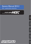
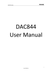
MH
Series
TM
CONTROL UNIT
Installation Manual
2544831-A
PROPRIETARY NOTICE
This document and the information disclosed herein are proprietary data of
WALTER MEIER LTD. Neither this document nor the information contained herein
shall be reproduced used, or disclosed to others without the written authorization of
WALTER MEIER LTD., except to the extent required for installation or maintenance
of recipient’s equipment. All references to the NORTEC name should be taken as
referring to WALTER MEIER LTD.
LIABILITY NOTICE
WALTER MEIER LTD. does not accept any liability for installations of humidity equipment installed
by unqualified personnel or the use of parts/components/equipment that are not authorized or
approved by WALTER MEIER LTD.
COPYRIGHT NOTICE
Copyright 2008, WALTER MEIER LTD. All rights reserved.
RECORD OF REVISIONS
For each revision, put the revised pages in your manual and discard the superseded pages. Write the
revision number and revision date, date put in manual, and the incorporator’s initials in the applicable
columns on the Record of Revisions.
Revision
Number
Revision
Date
Date Put
In Manual
By
Revision
Number
Revision
Date
Date Put
In Manual
By
TABLE OF CONTENTS
Subject
Page
10-00 INTRODUCTION
1.
INTRODUCTION . . . . . . . . . . . . . . . . . . . . . . . . . . . . . . . . . . . . . . . . . . . . . . . . . . . . . . . . . . . . . . . . . . . . . . . . 2
1.1 NOTES ON THE OPERATING INSTRUCTIONS . . . . . . . . . . . . . . . . . . . . . . . . . . . . . . . . . . . . . . . . . . . . 2
1.2 SAFETY . . . . . . . . . . . . . . . . . . . . . . . . . . . . . . . . . . . . . . . . . . . . . . . . . . . . . . . . . . . . . . . . . . . . . . . . . . . . 2
2.
OPERATING THE MH CONTROL UNIT . . . . . . . . . . . . . . . . . . . . . . . . . . . . . . . . . . . . . . . . . . . . . . . . . . . . . . 3
2.1 FUNCTION OF THE DISPLAY AND OPERATING ELEMENTS . . . . . . . . . . . . . . . . . . . . . . . . . . . . . . . . . 3
2.2 SWITCHING THE CONTROL UNIT ON AND OFF . . . . . . . . . . . . . . . . . . . . . . . . . . . . . . . . . . . . . . . . . . . 4
2.3 REMOTE OPERATING AND FAULT INDICATION . . . . . . . . . . . . . . . . . . . . . . . . . . . . . . . . . . . . . . . . . . . 4
2.4 OVERVIEW AND OPERATING OF THE MENU . . . . . . . . . . . . . . . . . . . . . . . . . . . . . . . . . . . . . . . . . . . . . 5
3.
EXPLANATION OF CONFIGURATION SETTINGS . . . . . . . . . . . . . . . . . . . . . . . . . . . . . . . . . . . . . . . . . . . . . 6
3.1 EXPLANATION OF THE STATUS INFORMATION . . . . . . . . . . . . . . . . . . . . . . . . . . . . . . . . . . . . . . . . . . . 6
3.2 EXPLANATION OF UNIT INFORMATION . . . . . . . . . . . . . . . . . . . . . . . . . . . . . . . . . . . . . . . . . . . . . . . . . . 9
3.3 EXPLANATION OF ERROR HISTORY LIST . . . . . . . . . . . . . . . . . . . . . . . . . . . . . . . . . . . . . . . . . . . . . . . 10
10-10 CONFIGURATION
1.
CONFIGURATION . . . . . . . . . . . . . . . . . . . . . . . . . . . . . . . . . . . . . . . . . . . . . . . . . . . . . . . . . . . . . . . . . . . . . . 12
1.1 UNIT SETTINGS . . . . . . . . . . . . . . . . . . . . . . . . . . . . . . . . . . . . . . . . . . . . . . . . . . . . . . . . . . . . . . . . . . . . . 12
1.2 MODBUS SETTINGS . . . . . . . . . . . . . . . . . . . . . . . . . . . . . . . . . . . . . . . . . . . . . . . . . . . . . . . . . . . . . . . . . 21
10-20 OPERATIONAL FUNCATIONS
1.
OPERATIONAL FUNCATIONS . . . . . . . . . . . . . . . . . . . . . . . . . . . . . . . . . . . . . . . . . . . . . . . . . . . . . . . . . . . . 24
1.1 CARRYING OUT MANUAL DRAINING / PIPE FLUSHING . . . . . . . . . . . . . . . . . . . . . . . . . . . . . . . . . . . . 24
1.2 RESETTING THE MAINTENANCE INDICATION . . . . . . . . . . . . . . . . . . . . . . . . . . . . . . . . . . . . . . . . . . . . 25
1.3 RESETTING THE HOURS METER OF THE UV LAMP . . . . . . . . . . . . . . . . . . . . . . . . . . . . . . . . . . . . . . . 26
10-30 TROUBLESHOOTING
1.
FAULT INDICATION . . . . . . . . . . . . . . . . . . . . . . . . . . . . . . . . . . . . . . . . . . . . . . . . . . . . . . . . . . . . . . . . . . . . 28
1.1 FAULT INDICATION
28
1.2 TROUBLESHOOTING . . . . . . . . . . . . . . . . . . . . . . . . . . . . . . . . . . . . . . . . . . . . . . . . . . . . . . . . . . . . . . . . 29
1.3 RESETTING THE ERROR INDICATION . . . . . . . . . . . . . . . . . . . . . . . . . . . . . . . . . . . . . . . . . . . . . . . . . . 34
WARRANTY
THIS PAGE INTENTIONALLY LEFT BLANK
10-00
INTRODUCTION
10-00
Page 1
2008-12-03
1. INTRODUCTION
1.1
NOTES ON THE OPERATING INSTRUCTIONS
Limitation
These operating instructions are an addendum to the installation and operating
instructions for the Nortec MH and describe the operating of the MH control unit, which
is used with the models Nortec MHTC Flow, MHB Reflow, MHTC Reflow. These
operating instructions are meant for well trained personnel being sufficiently qualified.
Safekeeping
Please safeguard these operating instructions in a safe place, where they can be
immediately accessed. If the equipment changes hands, the documentation must be
passed on to the new operator.
If the documentation gets lost, please contact your local Nortec representative.
Copyright protection
The present operating instructions are protected under the Copyright Act. Passing-on
and reproduction of the manual (or part thereof) as well as exploitation and
communication of the contents are prohibited without written permission by the
manufacturer. Violation of copyright terms is subject to legal prosecution and arises
liability for indemnification. The manufacturer reserves the right to fully exploit
commercial patent rights.
1.2
SAFETY
Every person operating the MH control unit must have read and understood the
operating instructions of the MH control unit as well as the installation and operating
instructions of the Nortec MH (specially the safety instructions).
Knowing and understanding the contents of the operating instructions of the MH
control unit and the installation and operating instructions of the Nortec MH is a basic
requirement for protecting the personnel against any kind of danger, to prevent faulty
operation, and to operate the unit safely and correctly.
10-00
Page 2
2008-12-03
2. OPERATING THE MH CONTROL UNIT
2.1
FUNCTION OF THE DISPLAY AND OPERATING ELEMENTS
Figure 1. Display
10-00
Page 3
2008-12-03
2.2
SWITCHING THE CONTROL UNIT ON AND OFF
NOTE: For putting the unit into operation and taking the unit out of operation please
follow the procedures described in the installation and operating instructions for the
Nortec MH.
Switching the MH control unit on
The control carries out a system test, during which all the
LEDs light up and the opposite display is shown. If a failure
occurs on the system test, a corresponding error message is
shown in the display.
After the system test the control is in normal operation mode.
The display shows the standard operating display. Note: The
contents of the standard operating display depends on the
type (MHTC Flow, MHTC Reflow), the actual operating
status and on the configuration of the Nortec MH and can
differ from the opposite display.
Switching the MH control unit off
The display goes out. On models MHB Reflow and MHTC Reflow the drain valve
opens and the water tub empties.
Note: The different hygiene functions (regular draining, flushing of the supply line, etc.)
remain active also in times without humidification / cooling demand, the control unit
should only be switched off for maintenance or, troubleshooting, or to disable
completely operation (as in seasonal shutdown).
2.3
REMOTE OPERATING AND FAULT INDICATION
If your control is equipped with a remote indication board (accessory) the following
operating status are shown remotely:
Activated remote
When?
Display on Unit
indication relay
A fault is present, further
Red LED lights. An error
H1 “Error”
operation is not possible
message is shown in the
display
Yellow LED lights. The
Maintenance or UV lamp
H2 “Service”
service warning message
(option) replacement is
is shown in the display
due. The unit remains
operational for a certain
time
Unit is humidifying
Green LED lights
H3 “Humidification”
Unit ready for operation
Unit switch lights
H4 “Unit on”
10-00
Page 4
2008-12-03
2.4
OVERVIEW AND OPERATING OF THE MENU
The operating and display is operated via the four
keys located just below the display. The four status
fields at the bottom of the display show the current
function of the keys.
Keys
Figure 2. Menu Overview
10-00
Page 5
2008-12-03
3. EXPLANATION OF CONFIGURATION SETTINGS
3.1
EXPLANATION OF THE STATUS INFORMATION (INDICATION STATUS)
In normal operation mode the control unit is in the status level. The status level forms a loop
that includes several pages holding operating information which can be accessed with the
arrow keys. The various displays of the status level are shown below.
Standard operating display
The appearance of the standard operating display depends on the actual operating status and
the configuration of the Nortec MH
Standard operating display with external control via the
external controller.
Standby (no humidity demand) or Demand % (humidity
demand present).
Standard operating display with internal control.
- Actual humidity in %rh.
- Configured humidity setpoint in %rh.
Info Page: Settings
- Software version.
- Selected control signal source.
- Configured control signal range.
- Configured Modbus address of the unit.
Info Page: Performance data
- Configure power limitation in % of the maximum output.
- Actual output unit A in kg/h.
- Actual total output in kg/h (the same as Capacity A unless a
second module is connected to control unit).
.
Info Page: Operating hours
- Total operating hours of the Nortec MH.
- Remaining operating hours to the next maintenance.
10-00
Page 6
2008-12-03
Info Page: Clean Trg. 1
This page shows the current settings for the time based and externally activated
forced draining/box cleaning (MHTC Reflow) or the box cleaning (MHTC Flow),
respectively.
Note: Wash = draining with simultaneous box cleaning (MHTC Reflow) or box
cleaning only (MHTC Flow), Drain = draining only.
– Time controlled draining/box cleaning (Timer).
– Actual time of day.
– Point in time of the next draining/cleaning cycle.
– Configured cleaning mode.
– Interval controlled draining/box cleaning (Periodic).
– Configured interval time in hours.
– Remaining time in hours up to the next
draining/cleaning cycle.
– Configured cleaning mode.
– Externally controlled draining/box cleaning
(Demand).
– Actual status of the draining/cleaning demand.
– Configured cleaning mode.
– Clean Trg. 1 deactivated (can appear only with
module MHTC Flow).
Info Page: Clean Trg. 2 (Note: This page is not shown with model MHTC Flow)
– Fill cycle controlled draining (Cycle).
– Number of fill cycles between cleaning/draining
cycles.
– Remaining fill cycles up to the next draining.
– Cleaning mode (Wash= Draining with simultaneous
box cleaning or box cleaning only, Drain= draining
only).
– Conductivity controlled draining/cleaning (µSensor) ->Option.
– Set conductivity limit value inn µS/cm.
– Actual conductivity value of the water in the tub in
µS/cm.
– Configured cleaning mode.
– Operation-dependent draining deactivated (Off).
10-00
Page 7
2008-12-03
Info Page: Box drying
This page shows the settings for box drying.
– Time controlled box drying (Timer)
– Actual time of day
– Point in time of the next drying cycle
– Interval controlled box drying (Periodic)
– Configured interval time in hours
– Remaining time in hours up to the next drying cycle
Info Page: Supply line flushing function/water quantity reduction function
– Indicates if the supply line flushing function.
– Indicates if the "Softstart" water conservation function
is enabled.
Info Page: UV Module (option)
Indicates if the UV water treatment option is enabled
(Note: UV treatment requires optional components be
installed).
10-00
Page 8
2008-12-03
3.2
EXPLANATION OF UNIT INFORMATION
Path: Main menu > Info > Unit Status
Press <> and <> keys, in order to select the unit information
available in the list:
– System Operation Hour:
Total operating hours of the control unit (unit on) since the initial
commissioning of the unit.
– Relay Humidity:
Actual status of the remote indication relay “Humidify”.
– Relay Service:
Actual status of the remote indication relay “Service”.
– Relay Error:
Actual status of the remote indication relay “Error”.
– Relay Unit On:
Actual status of the remote indication relay “Unit on”.
– Drain Valve:
Actual operating status of the drain valve.
– Inlet Valve:
Actual operating status of the inlet valve.
– Pump:
Actual operating status of the circulation pump.
– UV Lamp:
Actual operating status of the UV lamp
– Stage 1 Valve: Actual operating status of the step valve 1
– Stage 2 Valve: Actual operating status of the step valve 2
– Stage 3 Valve: Actual operating status of the step valve 3
– Pressure Sensor (MHTC Flow only):
Actual operating status of the minimum pressure switch
– Max Level Sensor (MHTC Reflow only):
Actual operating status of the minimum level sensor
– Thermal Contact (MHTC Reflow only):
Actual operating status of the thermal contact (pump motor
protection)
– Extension Present:
Indication, whether or not a unit extension is present.
– Wash Demand:
Actual status of the external demand triggering a wash cycle.
Press the <Esc> key several times to quit the information list
and to return to the standard operating display.
10-00
Page 9
2008-12-03
3.3
EXPLANATION OF ERROR HISTORY LIST
The last 10 faults that occurred during operation are saved in the error history list and can be
reviewed.
Path: Main menu > Info > Error History
The last error that occurred is shown with:
– Current Error being viewed / Total number of errors
recorded.
– date and time of occurrence
– error code (Warning: W..., Error: E...– error message
– additional info text regarding the error
Press <Å> and <Æ> keys, in order to select further
error messages in the list.
Press the <Esc> key several times to quit the error
history list and to return to the standard operating
display.
10-00
Page 10
2008-12-03
10-10
CONFIGURATION
10-10
Page 11
2008-12-03
1. CONFIGURATION
1.1
UNIT SETTINGS
1.1.1 Launching the unit settings menu
Path: Main menu > User > Password entry:
8808 > Settings
Press the <È> and <Ç> keys in order to
select the individual settings in the settings
menu.
Detailed information on the different settings
are found in the following chapters sections.
1.1.2 Select dialogue language
Select “Language” in the settings menu, then
press the <Set> key. In the following
modification dialogue select the desired
dialogue language.
After confirmation, the unit automatically
switches to the selected dialogue language.
Factory setting: English
Options: French, Spanish
10-10
Page 12
2008-12-03
1.1.3 Control Settings
Select “Controls” in the settings menu, then
press the <Set> key.
The control settings appear. The settings
available depend on the selected signal
source and the control type. The opposite
display shows the maximum number of
settings available.
DESCRIPTION OF THE SETTINGS
Selecting the signal source.
SignalSource
Hum.Control:
Controlsign.
Hum.Setpoint:
P-Band:
Integr.-Time:
Factory setting: Analog
Options:
Analog
Modbus
Selecting the control type.
Factory setting: External
Options: External (external continuous controller)
24VOn/Off (external On/Off humidistat)
Int. (P) (Internal P controller)
Int. (PI) (Internal PI controller)
Selecting the control signal.
NOTE: This setting is available only if control type
“External”, “Int. (P)” or “Int. (PI)” is selected.
Factory setting: 0–10V
Options: 0–5V, 1–5V, 0–10V, 2–10V, 0–16V, 3.2–
16V, 0–20mA, 4–20mA
Setting the nominal humidity value inn %rh.
NOTE: This setting is available only if the internal P
or PI controller is activated.
Factory setting: 50 %rH
Setting range: 20...99 %rH
Setting the proportional range inn % for the internal
P/PI conntroller.
NOTE: This setting is available only if the internal P
or PI controller is activated.
Factory setting: 18 %
Setting range: 1...100 %
Setting the integral time in minutes for the internal
PI controller.
NOTE: This setting is available only if the internal P
or PI controller is activated.
Factory setting: 18 Minutes
Setting range: 1...60 Minutes
10-10
Page 13
2008-12-03
.
1.1.4 Setting the capacity limitation
Select “Power Limit” in the settings menu,
then press the <Set> key. In the upcoming
modification dialogue set the desired capacity
limitation in % of the maximum capacity of the
humidifier.
Factory setting: 100 %
Setting range: 30...100 %
1.1.5 Configuring the supply pipe flushing
Select “Inlet Flush” in the settings menu, then
press the <Set> key.
Used to configure the unit to flush supply lines
even if there is no demand signal. You can;
- enable / disable inlet flush
- set length of flush
- set time between flushes
DESCRIPTION OF THE SETTINGS
Inlet Flush
Enable or disable the supply pipe flushing.
Factory setting:
Options:
Drain Time
Setting the flushing time in seconds.
Factory setting:
Setting range:
Periodic Int
Page 14
2008-12-03
60s
5...600s
Setting the time without demand after which
the supply pipe should be flushed.
Factory setting:
Setting range:
10-10
On
On (enable)
Off (disable)
12.0 h
0.5 ... 24.0 h
1.1.6 Setting the Cleaning Mode (MHTC Reflow only)
NOTE: The cleaning mode may only be set with the MHTC Reflow. With the
cleaning mode you determine whether the humidification boxes will be washed
simultaneously during a draining or operation dependent draining /cleaning
cycle. This option does not appear for other models.
Select “Clean Mode” in the settings menu, then
press the <Set> key. In the upcoming
modification dialogue select the desired
cleaning/draining mode.
Factory setting: Drain
Options:
Drain (draining only)
Wash (Draining w/box cleaning)
NOTE: During operation, the washing process of the humidification boxes can
lead to a temporary humidity increase.
10-10
Page 15
2008-12-03
1.1.7 Configuring the cleaning trigger 1 (Clean Trg. 1)
With the cleaning trigger 1 settings you determine whether the forced
draining/cleaning (MHTC Reflow) or the box cleaning (MHTC Flow) is time or
interval controlled or triggered via an external signal. The forced draining can be
deactivated, however the box cleaning can be deactivated. The forced draining
cannot be deactivated for the MHTC Reflow. The washing can be deactivated
for either the MHTC Flow or Reflow.
Note: the forced cleaning/draining serves to empty the water tub regularly and
independent of the operation time of the Nortec MH.
Select “Clean Trg. 1” in the settings menu, then
press the <Set> key. The current settings for
the forced draining/box cleaning appear. The
available settings depend on whether the
interval controlled (Periodic (factory setting),
timer controlled (Timer) or external signal
controlled (Demand) triggering of the forced
draining/box cleaning is selected.
Interval controlled draining/box cleaning
(Periodic). With Periodic Int you can determine
in which time intervals the draining/box cleaning
is performed (setting range: 0.5 ...24 .0h,
factory setting: 2.0h).
Time controlled draining/box cleaning
(Timer)With the parameters “time 1” to “time 4”
you can define up to four times of day to start
the draining/box cleaning (factory setting: no
starting times defined).
Triggering the draining/box cleaning via an
external signal (Demand). In order to trigger
the draining/box cleaning via an external signal
a potential-free contact (B4 ) must be
connected to the control board of the control
unit MH. Closing the contact results in a
draining/box cleaning cycle.
Cleaning trigger 1 deactivated (Off)Note: this
option is only available/visible for model MHTC
Flow.
10-10
Page 16
2008-12-03
1.1.8 Configuring the cleaning trigger 2 (Clean Trg. 2) (MHTC Reflow only)
Note: The cleaning trigger 2 to configure operation dependent draining appears
only with the MHTC Reflow. With the cleaning trigger 2 settings you determine
whether operation dependent draining is triggered depending on the fill cycles or
on the conductivity of the water in the water tub (option) or whether the cleaning
trigger 2 should be deactivated.
Select “Clean Trg. 2” in the settings menu, then
press the <Set> key. The current settings for
the operation dependent draining appear. The
settings available depend on whether the
operation dependent draining is deactivated
(Off, factory setting) or the fill cycle (Cycle) or
the conductivity controlled (µ Sensor) triggering
of the operation dependent draining is selected.
Operation dependent draining deactivated (Off)
Fill cycle controlled draining (Cycle). With the
parameter “Cycle” you can determine after how
many filling cycles a drain is performed (setting
range: 10...10000, factory setting: 100).
Conductivity controlled draining (µ Sensor)
(Requires optional components). With the
parameter “µS Limit” you can set a conductivity
limit value. If during operation the conductivity
value of the water in the tub reaches the set
limit, a draining is performed (setting range:
10...5 000 µS, factory setting: 1000µS).
10-10
Page 17
2008-12-03
1.1.9 Configuring the humidification box drying
An occasional drying of the humidification boxes helps prevent germs and bacteria
from developing in the humidification boxes. The drying process can be time triggered
or, interval controlled, or it can be deactivated.
Note: During operation, the drying process of the humidification boxes can lead to a
temporary humidity decrease.
Select “Box Drying” in the settings menu, then
press the <Set> key. The current settings for
the box drying function appear. The settings
available depend on whether the box drying
function is deactivated (Off, factory setting) or
whether the time controlled (Timer) or the
interval controlled (Periodic) triggering of the
drying function is selected.
Drying function deactivated (Off ---> factory
setting)
Time controlled drying (Timer)With the
parameters “time 1” to “time 4 ” you can define
up to four times of day to start a box drying
process (factory setting: no starting times
defined).
Interval controlled drying (Periodic) With the
parameter “Periodic Int” you can determine inn
which time intervals a box drying process is
performed (setting range: 0.5 ...24 .0h, factory
setting: 12.0h).
10-10
Page 18
2008-12-03
1.1.10 Configuring the Humidifier Maintenance Interval
Select “Maintenance” in the settings menu,
then press the <Set> key. In the following
dialogue set the desired maintenance interval
time in hours. After the maintenance interval
time has elapsed a maintenance message
appears in the display and the yellow LED
lights up. If the maintenance is not performed
and the maintenance indication is not reset
within a certain time (168 h) , an error
message is triggered. Factory setting: 800 h
Setting range: 100... 50000 h
Note: to determine the maintenance interval
time please refer to 1.3 in section 10-40 of the
installation and operating instructions for the
Nortec MH.
1.1.11 Activating/deactivating the softstart function
If the mats in the humidifier boxes became dry due to a operation interruption, they
need a certain time until they are again moistened with water. In order to prevent too
much water flows over the humidification boxes in this phase and water droplets are
carried in the air flow, the amount of water can be reduced for a fixed time with the
“Softstart” function.
Select “Softstart” in the settings menu, then
press the <Set> key. In the modification
dialogue you can activate or deactivate the
softstart function. Factory setting: Off Options:
Off (Softstart function deactivated)
On (Softstart function activated)
10-10
Page 19
2008-12-03
1.1.12 Performing remote relay tests
With the test functions under “Remote Test” you can check the function of the relays
“Humidification”, “Service”, “Error” and “Unit on”.
Select “Remote Test” in the settings menu,
then press the <Set> key.
Press the <Ç> and <È>
keys in order to select the relay you want to
test and press the <Set> key to
activate/deactivate the corresponding relay for
testing.
1.1.13 Setting the date
Select “Date” in the settings menu, then press
the <Set> key. In the following dialogue set the
actual date (format “tt.mm.jj”).
1.1.14 Setting the time
Select “Time” in the settings menu, then press
the <Set> key. In the following dialogue set the
actual time (format “hh.mm”).
1.1.15 Setting the display contrast
Select “Contrast” in the settings menu, then
press the <Set> key. In the following dialogue
set the desired value for the display contrast.
Factory setting: 20
Setting range: 0 (no display) ...100 (display
turns black).
10-10
Page 20
2008-12-03
1.2 Modbus Settings
Select the Modbuus menu: Path: Main menu >
User > Password entry: 8808 > Modbus
The settings for the Modbuus appear.
Description of Modbus Settings
Modbus Add.:
Setting the modbus address of the Nortec MH.
Factory setting: 1
Setting range: 1...247
Parity:
Selecting the parity bit for the data
transmission.
Factory setting: None.
Options: None1, None2, Odd, Even
Timeout:
Setting the time out time for the data
transmission.
Factory setting: 5
Seconds Setting range: 1...600 Seconds
10-10
Page 21
2008-12-03
THIS PAGE INTENTIONALLY LEFT BLANK
10-10
Page 22
2008-12-03
10-20
OPERATIONAL
FUNCTIONS
10-20
Page 23
2008-12-03
1. OPEARTIONAL FUNCTIONS
1.1
CARRYING OUT MANUAL DRAINING / PIPE FLUSHING
To carry out a manual draining (MHTC Reflow) or pipe flushing (MHTC Flow) proceed
as follows:
Drain
1. Briefly press the drain key. The drain/flush
dialogue appears in the display.
2. Press the <Start> key.
– Models MHTC Reflow: The drain valve opens
after a delay of up to 3 minutes and the water tub
empties. The yellow LED flashes.
– Model MHTC Flow: The inlet valve and the
flushing valve open and the pipe is flushed. The
yellow LED flashes.
To stop the drain/flush cycle press the <Stop> key.
Note: By pressing the <Esc> key the control unit
returns to the standard operating display. A
drain/flush cycle in progress will be stopped
automatically.
10-20
Page 24
2008-12-03
1.2
RESETTING THE MAINTENANCE INDICATION
After completing maintenance work, the maintenance indication (yellow LED lights)
must be reset on the models MHTC Flow, MHB Reflow, MHTC Reflow.
Note: If the maintenance indication is not reset within 168 hours a fault is triggered and
the unit stops operation.
Select the maintenance menu:
Path: Main menu > User > Password entry: 8808
> Maintenance
Select “Module A”, then press the <Set> key.
Select "Stage Reset”, then press the <Set> key.
The reset dialogue shows up in the display. Press
the <Yes> key to reset the maintenance hours of
the unit.
Note: Press the <Esc> or <No> key if you wish to
abort the reset procedure.
To return to the standard operating display press
the <Esc> key several times.
10-20
Page 25
2008-12-03
1.3
RESETTING THE HOURS METER OF THE UV LAMP
After replacing the UV lamp (option) the hours meter of the UV lamp must be reset.
Note: If the hours meter of the UV lamp is not reset within 168 hours the UV
maintenance warning an error message is triggered.
Select the maintenance menu:
Path: Main menu > User > Password entry: 8808
> Maintenance
Select “Module A”, then press the <Set> key.
Select "UV lamp Rst”, then press the <Set> key.
The reset dialogue shows up in the display.
Press the <Yes> key to reset the hours meter of
the UV lamp.
Note: Press the <Esc> or <No> key if you wish to
abort the reset procedure.
To return to the standard operating display press
the <Esc> key several times.
10-20
Page 26
2008-12-03
10-30
TROUBLESHOOTING
10-30
Page 27
2008-12-03
1. FAULT INDICATION
1.1
FAULT INDICATION
Malfunctions during operation are indicated by a corresponding warning or error message in
the display of the control unit:
Warning messages (additionally to the error message the red LED is on)
Further operation is still possible. If the cause of the
malfunction disappears of its own accord, the
warning message will automatically switch off. If the
cause of the malfunction does not disappear even
after a longer period of time, an error message is
triggered.
Error message (additionally to the error message the red LED is on)
Further operation is not possible. The malfunction
is stored in the error list.
By pressing the <Info> key additional information
are displayed for each warning or error message.
By pressing the <Esc> key the control unit
returns to the standard operating display.
10-30
Page 28
2008-12-03
1.2
TROUBLESHOOTING
1.2.1 System Faults
Warning
LED
Display
MH Card missing (Test run
possible)
Red
flashes
Error
LED
Display
MH Card Missing
Red lights
--
MH Card is Empty
Red lights
--
--
MH Card is defective
Red lights
--
--
MH Card is incompatible
Red lights
--
--
Unit Module B missing
Red lights
--
--
Wrong parameter settings
Red lights
--
--
--
--
--
Cause
Remedy
No MH Card
installed on the
control board.
Install MH
Card or start
test run.
No data stored on
the MH Card
Install new
MH Card.
Invalid data stored
on the MH Card
Install new
MH Card.
The MH Card is
not compatible
with the hardware
or the basic
settings on the
control board.
Install new
MH Card.
Modify basic
settings.
No response from
module B. Flat
ribbon cable
interrupted or
disconnected
120V supply cable
disconnected.
Plug in flat
ribbon cable,
plug in 120V
supply
cable.
Data of CPU and
MH Card do not
match.
Install
correct MH
Card.
Contact your
Nortec
supplier.
CPU on control
board defective.
Replace
control
board.
CPU on control
board defective.
Replace
control
board.
Hardware Fault (flash)
Hardware Fault (clock)
10-30
Page 29
2008-12-03
1.2.2 Unit Faults
Warning
LED
Display
External safety chain is
open
Red
and
green
flash
Error level sensor
Red
flashes
Error
Display
LED
--
Error level sensor
Red
lights
Cause
Remedy
Air proving interlock
open.
If applicable,
check/turn on fan.
Air flow monitor
triggered
Check fan/filter of
the fan system.
Safety humidistat
triggered.
Wait, if applicable,
check safety
humidistat
The level sensor is
blocked or defective
(broken or shortcircuited).
Check/clean or
replace level
sensor. Check level
sensor with
ohmmeter: If no
water is in the tub,
the circuit of the
level sensor must
be closed. If the
water in the tub is
on maximum level
sensor must be
open.
Maximum filling time
exceeded (30 minutes)
Red
flashes
Maximum filling time
exceeded (more than 4
hours)
Red
lights
Note: This error
message is reset
automatically as
soon as the water
supply functions
again.
10-30
Page 30
2008-12-03
Water supply
blocked/shut-off valve
closed/water pressure
too low. Water
treatment unit (fully
demineralised water)
is regenerating.
Check water supply
(filter, pipes, etc.),
Check/open shutoff valve, Check
water pressure.
Inlet valve blocked or
defective.
Check strainer in
the inlet valve,
clean if necessary.
Replace inlet valve.
Drain valve open,
blocked in open
position or not
electrically
connected. Drain
valve is open unless
powered
Check/replace
drain valve,
connect drain
valve.
Leakage in the water
drain system.
Check/seal water
drain system.
When draining the water
tub float is not open
within 8 minutes
When draining the water
tub the float is not open
within 4 hours
Red
flashes
Red
lights
Conductivity of the water in
the tub too high
Red
flashes
Conductivity of the water
in the tub too high
Red
lights
Drain valve
blocked/defective or
clogged.
Check/clean or
replace drain valve.
Siphon clogged.
Clean siphon.
Relay defective
(weld-shut).
Replace control
board.
Level sensor stucked
or short circuited.
Clean/Replace
level sensor.
Backpressure in the
siphon.
Install special
siphon.
Conductivity after
draining, restart or
cleaning
cycle during 10
minutes higher than
the set nominal value.
Increase the
nominal value or
enhance water
quality.
Conductivity sensor
defective.
Replace
conductivity sensor.
Conductivity
transmitter defective.
Replace
conductivity
transmitter.
10-30
Page 31
2008-12-03
Warning
LED
Display
Maintenance due
Error
LED
Display
Maintenance not performed
and/or maintenance
indication not reset
Red
flashes
and
yellow
lights
red and
yellow
lights
Maximum lifespan of the
UV lamp reached
Maximum lifespan of the
UV lamp reached
red
flashes
and
yellow
lights
red and
yellow
light
No signal from humidity
sensor
No signal from humidity
sensor
Red
flashes
Red
lights
10-30
Page 32
2008-12-03
Cause
Remedy
Maintenance due.
Perform
maintenance
according to
section 10-40 of
the installation
and operating
instructions
for the Nortec MH.
Then, reset the
maintenance
indication.
Maintenance not
performed and/or
maintenance
indication not reset
within 168 h (1
week).
Perform
maintenance
according to
section 10-40 of
the installation
and operating
instructions
for the Nortec MH.
Then, reset the
maintenance
indication.
Maximum lifespan
of the UV lamp
reached.
Replace UV lamp
and clean glass
tube
UV lamp not
replaced or hours
counter of the UV
lamp not reset after
replacement of the
UV lamp. Unit
switches off after
168 hours.
Replace UV lamp
and clean glass
tube (see 1.4.2 in
section 10-40),
then reset hours
counter of the UV
lamp.
Wrong UV lamp
installed.
Install correct UV
lamp.
Sensor cable not
connected or
sensor cable
interrupted.
Connect/replace
sensor cable.
Humidity sensor
defective.
Replace humidity
sensor.
No signal from
conductivity sensor
No signal from
conductivity sensor
Red
flashes
Red
lights
Nortec SH2 deactivated
via Modbus
Modbus system failed
Red
flashes
Red
lights
Sensor cable not
connected or
sensor cable
interrupted.
Connect/replace
sensor cable.
Conductivity
transmitter
defective or wrong
version
(conductivity
constant).
Replace
conductivity
transmitter.
Conductivity
transmitter not
configured
correctly.
Contact your
Nortec supplier.
Conductivity sensor
defective.
Replace
conductivity
sensor.
Nortec MH
deactivated via
Modbus.
None or activate
Nortec MH via
Modbus.
Modbus system
failed.
Check/activate
Modbus system.
Timeout. No
activity from
Modbus
Activate Modbus
system
Timeout Modbus
Red
flashes
--
Red
lights
Cleaning of humidification
boxes in progress
--
--
--
Cleaning of
humidification
boxes in progress.
None (wait).
--
--
Draining of water
tub in progress.
None (wait).
Draining of water tub in
progress
--
10-30
Page 33
2008-12-03
Water pressure too low
(flow only)
Water pressure for more than
4 hours too low (flow only)
Red
flashes
Red
Lights
Water supply
blocked/shut-off
valve closed/water
pressure too low.
Water treatment
unit (fully
demineralised
water) is
regenerating.
Check water
supply (filter,
pipes, etc.),
Inlet valve blocked
or defective.
Check strainer in
the inlet valve,
clean if necessary.
Replace inlet
valve.
Replace flushing
valve.
Flushing valve
leaking.
1.3
Check/open
shut-off valve.
Check water
pressure.
RESETTING THE ERROR INDICATION
To reset the error indication: Investigate and correct cause of error. Turn control panel
ON/OFF switch to OFF.
Wait approx. 5 seconds, then turn control panel ON/OFF switch to On position.
Note: If the fault has not been eliminated, the error indication reappears after a short
while.
10-30
Page 34
2008-12-03
WARRANTY
(1) WALTER MEIER INC. and/or WALTER MEIER LTD. (hereinafter collectively referred
to as THE COMPANY), warrant for a period of two years after installation or 30 months
from manufacturer’s ship date, whichever date is earlier, that THE COMPANY’s
manufactured and assembled products, not otherwise expressly warranted (with the
exception of the cylinder), are free from defects in material and workmanship. No
warranty is made against corrosion, deterioration, or suitability of substituted materials
used as a result of compliance with government regulations.
(2) THE COMPANY’s obligations and liabilities under this warranty are limited to furnishing
replacement parts to the customer, F.O.B. THE COMPANY’s factory, providing the
defective part(s) is returned freight prepaid by the customer. Parts used for repairs are
warranted for the balance of the term of the warranty on the original humidifier or
90 days, whichever is longer.
(3) The warranties set forth herein are in lieu of all other warranties expressed or implied
by law. No liability whatsoever shall be attached to THE COMPANY until said products
have been paid for in full and then said liability shall be limited to the original purchase
price for the product. Any further warranty must be in writing, signed by an officer of
THE COMPANY.
(4) THE COMPANY’s limited warranty on accessories, not of the companies manufacture,
such as controls, humidistats, pumps, etc. is limited to the warranty of the original
equipment manufacturer from date of original shipment of humidifier.
(5) THE COMPANY makes no warranty and assumes no liability unless the equipment is
installed in strict accordance with a copy of the catalog and installation manual in effect
at the date of purchase and by a contractor approved by THE COMPANY to install
such equipment.
(6) THE COMPANY makes no warranty and assumes no liability whatsoever for
consequential damage or damage resulting directly from misapplication, incorrect
sizing or lack of proper maintenance of the equipment.
(7) THE COMPANY retains the right to change the design, specification and performance
criteria of its products without notice or obligation.
U.S.A.
Walter Meier (Climate USA) Inc.
CANADA
Walter Meier (Climate Canada) Ltd.
826 Proctor Avenue
Ogdensburg, NY 13669
TEL: 1-866-NORTEC-1
EMAIL: [email protected]
WEBSITE: www.humidity.com
2740 Fenton Road
Ottawa, ON K1T 3T7
TEL: 1-866-NORTEC-1
FAX: (613) 822-7964
Authorized Agent: