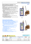
1
MiniCuret
Customer Product Manual
Part 7119745C
Issued 08/07
global UV solutions
NORDSON UV LTD • SLOUGH, BERKSHIRE • UK
Nordson Corporation welcomes requests for information, comments, and inquiries about its products. General information
about Nordson can be found on the Internet using the following address: http://www.nordson.com.
Address all correspondence to:
Nordson UV Limited
Attn: Customer Service
816 Leigh Road
Slough, Berkshire SL1 4BD
Notice
This is a Nordson Corporation publication which is protected by copyright. Original copyright date 2006.
No part of this document may be photocopied, reproduced, or translated to another language without the prior written
consent of Nordson Corporation. The information contained in this publication is subject to change without notice.
© 2007 All rights reserved.
Trademarks
AccuJet, AeroCharge, AquaGuard, Asymtek, Automove, Autotech, Baitgun, Blue Box, CF, CanWorks, Century,
Clean Coat, CleanSleeve, CleanSpray, Control Coat, Cross-Cut, Cyclo-Kinetic, Dispensejet, DispenseMate, Durafiber,
Durasystem, Easy Coat, Easymove Plus, Econo-Coat, EFD, ETI, Excel 2000, Flex-O-Coat, FlexiCoat, Flexi-Spray,
Flow Sentry, Fluidmove, FoamMelt, FoamMix, Helix, Horizon, Hot Shot, Isocoil, Isocore, Iso-Flo, JR, KB30, Kinetix,
Little Squirt, Magnastatic, MEG, Meltex, Microcoat, MicroSet, Millennium, Mini Squirt, Moist-Cure, Mountaingate,
MultiScan, Nordson, OmniScan, OptiMix, Package of Values, Patternview, PluraFoam, Porous Coat, PowderGrid,
Powderware, Prism, Pro-Flo, ProLink, Pro-Meter, Pro-Stream, PRX, RBX, Rhino, S. design stylized, Saturn, SC5,
Seal Sentry, Select Charge, Select Coat, Select Cure, Slautterback, Smart-Coat, Solder Plus, Spectrum, Spray Squirt,
Spraymelt, Super Squirt, Sure Coat, Tela-Therm, Trends, Tribomatic, UniScan, UpTime, Veritec, Versa-Coat,
Versa-Screen, Versa-Spray, Walcom, Watermark, and When you expect more.
are registered trademarks of Nordson Corporation.
ATS, Auto-Flo, AutoScan, BetterBook, Chameleon, CanNeck, Check Mate, Colormax, Control Weave,
Controlled Fiberization, CoolWave, CPX, Dura-Coat, Dry Cure, E-Nordson, EasyClean, Eclipse, Equi=Bead, Fill Sentry,
Fillmaster, Gluie, Heli-flow, Ink-Dot, Iso-Flex, Lacquer Cure, Maxima, MicroFin, MicroMax, Minimeter, Multifil, Origin,
PermaFlo, PluraMix, Powder Pilot, Powercure, Primarc, Process Sentry, PurTech, Pulse Spray, Ready Coat, Select Series,
Sensomatic, Shaftshield, SheetAire, Spectral, Spectronic, Speedking, Spray Works, Summit, Sure Brand, Sure Clean,
Sure Max, Swirl Coat, Tempus, Tracking Plus, Trade Plus, Universal, Vista, Web Cure, and 2 Rings (Design)
are trademarks of Nordson Corporation.
Part 7119745C
MiniCure 08-07
E 2007 Nordson Corporation
Introduction
O-1
Congratulations on the Purchase of
Your Nordson Product
Nordson equipment is engineered and manufactured in accordance with
strict specifications, using high quality components and state-of-the-art
technologies that assure reliable, long-term performance. Your product was
thoroughly tested for proper operation prior to shipment.
Before unpacking and installing your new equipment, please read this
manual. It is your guide to safe installation, productive operation and
effective maintenance. We recommend that you keep the manual available
for future reference.
Your Safety is Important to Nordson
Carefully read the Safety section. Your product is designed for safe
operation when used according to the published instructions. Potential
hazards exist when operating instructions are not followed.
Manufacturer of Equipment
Nordson UV Ltd.
816 Leigh Road,
Slough,
Berkshire
United Kingdom
SL1 4BD
Telephone:
Fax:
0044 (0) 1753--558--000
0044 (0) 1753--558--100
For a list of local Nordson organisations, see Nordson International.
E 2002 Nordson Corporation
UV_CONG_EN_B-- 0802
O-2
Introduction
UV_CONG_EN_B-- 0802
E 2002 Nordson Corporation
Introduction
O-1
Nordson International
http://www.nordson.com/Directory
Country
Phone
Fax
Austria
43-1-707 5521
43-1-707 5517
Belgium
31-13-511 8700
31-13-511 3995
Czech Republic
4205-4159 2411
4205-4124 4971
Hot Melt
45-43-66 0123
45-43-64 1101
Finishing
45-43-200 300
45-43-430 359
Finland
358-9-530 8080
358-9-530 80850
France
33-1-6412 1400
33-1-6412 1401
Erkrath
49-211-92050
49-211-254 658
Lüneburg
49-4131-8940
49-4131-894 149
Nordson UV
49-211-9205528
49-211-9252148
EFD
49-6238 920972
49-6238 920973
Italy
39-02-904 691
39-02-9078 2485
Netherlands
31-13-511 8700
31-13-511 3995
47-23 03 6160
47-23 68 3636
Poland
48-22-836 4495
48-22-836 7042
Portugal
351-22-961 9400
351-22-961 9409
Russia
7-812-718 62 63
7-812-718 62 63
Slovak Republic
4205-4159 2411
4205-4124 4971
Spain
34-96-313 2090
34-96-313 2244
Sweden
46-40--680 1700
46-40-932 882
Switzerland
41-61-411 3838
41-61-411 3818
Hot Melt
44-1844-26 4500
44-1844-21 5358
Finishing
44-161-495 4200
44-161-428 6716
Nordson UV
44-1753-558 000
44-1753-558 100
49-211-92050
49-211-254 658
Europe
Denmark
Germany
Norway
United
Kingdom
Hot Melt
Distributors in Eastern & Southern Europe
DED, Germany
E 2007 Nordson Corporation
All rights reserved
NI_EN_M-0307
O-2
Introduction
Outside Europe / Hors d’Europe / Fuera de Europa
S For your nearest Nordson office outside Europe, contact the Nordson
offices below for detailed information.
S Pour toutes informations sur représentations de Nordson dans votre
pays, veuillez contacter l’un de bureaux ci-dessous.
S Para obtener la dirección de la oficina correspondiente, por favor
diríjase a unas de las oficinas principales que siguen abajo.
Contact Nordson
Phone
Fax
DED, Germany
49-211-92050
49-211-254 658
Pacific South Division,
USA
1-440-685-4797
--
Japan
81-3-5762 2700
81-3-5762 2701
Canada
1-905-475 6730
1-905-475 8821
Hot Melt
1-770-497 3400
1-770-497 3500
Finishing
1-880-433 9319
1-888-229 4580
Nordson UV
1-440-985 4592
1-440-985 4593
Africa / Middle East
Asia / Australia / Latin America
Japan
North America
USA
NI_EN_M-0307
E 2007 Nordson Corporation
All rights reserved
Product Disposal Instructions
The symbol shown below and on the product means that the product is
classed as Electrical or Electronic Equipment and should not be disposed with
other commercial waste at the end of its working life.
The Waste of Electrical and Electronic Equipment (WEEE) Directive
(2002/96/EC) has been put in place to recycle products using best available
recovery and recycling techniques to minimise the impact on the environment,
treat any hazardous substances and avoid the increasing landfill.
Please contact Nordson UV at the end of the working life of this product for
advice on disposal. This product does contain non-RoHS compliant
components and should not be mixed with other commercial waste.
This page intentionally let blank
Table of Contents
i
Table of Contents
E 2007 Nordson Corporation
Safety . . . . . . . . . . . . . . . . . . . . . . . . . . . . . . . . . . . . . . . . . . . . . . . . . .
Introduction . . . . . . . . . . . . . . . . . . . . . . . . . . . . . . . . . . . . . . . . . . . . .
Qualified Personnel . . . . . . . . . . . . . . . . . . . . . . . . . . . . . . . . . . . . . .
Intended Use . . . . . . . . . . . . . . . . . . . . . . . . . . . . . . . . . . . . . . . . . . . .
Regulations and Approvals . . . . . . . . . . . . . . . . . . . . . . . . . . . . . . . .
Personal Safety . . . . . . . . . . . . . . . . . . . . . . . . . . . . . . . . . . . . . . . . .
Fire Safety . . . . . . . . . . . . . . . . . . . . . . . . . . . . . . . . . . . . . . . . . . . . . .
Label Definitions . . . . . . . . . . . . . . . . . . . . . . . . . . . . . . . . . . . . . . . . .
Refer to Manual . . . . . . . . . . . . . . . . . . . . . . . . . . . . . . . . . . . . . .
Warning! UV Radiation . . . . . . . . . . . . . . . . . . . . . . . . . . . . . . . . .
Safety Glasses . . . . . . . . . . . . . . . . . . . . . . . . . . . . . . . . . . . . . . .
Gloves . . . . . . . . . . . . . . . . . . . . . . . . . . . . . . . . . . . . . . . . . . . . . .
Capacitor . . . . . . . . . . . . . . . . . . . . . . . . . . . . . . . . . . . . . . . . . . . .
High Voltage . . . . . . . . . . . . . . . . . . . . . . . . . . . . . . . . . . . . . . . . .
Hot Surfaces . . . . . . . . . . . . . . . . . . . . . . . . . . . . . . . . . . . . . . . . .
Handle with Care . . . . . . . . . . . . . . . . . . . . . . . . . . . . . . . . . . . . .
Equipment safety . . . . . . . . . . . . . . . . . . . . . . . . . . . . . . . . . . . . . . . .
Introduction . . . . . . . . . . . . . . . . . . . . . . . . . . . . . . . . . . . . . . . . . .
High temperatures . . . . . . . . . . . . . . . . . . . . . . . . . . . . . . . . . . . .
High voltage . . . . . . . . . . . . . . . . . . . . . . . . . . . . . . . . . . . . . . . . . .
Fire risk . . . . . . . . . . . . . . . . . . . . . . . . . . . . . . . . . . . . . . . . . . . . .
Safety precautions while servicing . . . . . . . . . . . . . . . . . . . . . . .
Important Information . . . . . . . . . . . . . . . . . . . . . . . . . . . . . . .
Control System Cleaning . . . . . . . . . . . . . . . . . . . . . . . . . . . .
High Voltage Connections . . . . . . . . . . . . . . . . . . . . . . . . . . .
Lamphead Cleaning . . . . . . . . . . . . . . . . . . . . . . . . . . . . . . . . .
High Temperatures . . . . . . . . . . . . . . . . . . . . . . . . . . . . . . . . .
Safety UV curing . . . . . . . . . . . . . . . . . . . . . . . . . . . . . . . . . . . . . .
U.V. Radiation . . . . . . . . . . . . . . . . . . . . . . . . . . . . . . . . . . . . . .
Ozone Gas . . . . . . . . . . . . . . . . . . . . . . . . . . . . . . . . . . . . . . . .
Mercury . . . . . . . . . . . . . . . . . . . . . . . . . . . . . . . . . . . . . . . . . . .
U.V. Ink and Generated Products . . . . . . . . . . . . . . . . . . . . . .
System Checks . . . . . . . . . . . . . . . . . . . . . . . . . . . . . . . . . . . .
U.V. Permissible Exposure Levels . . . . . . . . . . . . . . . . . . . . . . .
Action in the Event of a Malfunction . . . . . . . . . . . . . . . . . . . . . . . .
Disposal . . . . . . . . . . . . . . . . . . . . . . . . . . . . . . . . . . . . . . . . . . . . . . . .
1-1
1-1
1-1
1-1
1-2
1-3
1-4
1-5
1-5
1-5
1-5
1-6
1-6
1-6
1-7
1-7
1-8
1-8
1-8
1-8
1-9
1-9
1-9
1-9
1-10
1-10
1-10
1-11
1-11
1-12
1-13
1-14
1-14
1-15
1-15
1-15
Description . . . . . . . . . . . . . . . . . . . . . . . . . . . . . . . . . . . . . . . . . . . . .
2-1
Transport & Handling . . . . . . . . . . . . . . . . . . . . . . . . . . . . . . . . . . .
Weights & Dimensions . . . . . . . . . . . . . . . . . . . . . . . . . . . . . . . . . . . .
Weight . . . . . . . . . . . . . . . . . . . . . . . . . . . . . . . . . . . . . . . . . . . . . .
Dimensions . . . . . . . . . . . . . . . . . . . . . . . . . . . . . . . . . . . . . . . . . .
Lifting . . . . . . . . . . . . . . . . . . . . . . . . . . . . . . . . . . . . . . . . . . . . . . . . . .
3-1
3-1
3-1
3-1
3-1
MiniCure 08-07
Part 7119745C
ii
Table of Contents
Part 7119745C
Installation . . . . . . . . . . . . . . . . . . . . . . . . . . . . . . . . . . . . . . . . . . . . .
4-1
Operation . . . . . . . . . . . . . . . . . . . . . . . . . . . . . . . . . . . . . . . . . . . . . .
Turning on the system power . . . . . . . . . . . . . . . . . . . . . . . . . . . . .
Starting the conveyor . . . . . . . . . . . . . . . . . . . . . . . . . . . . . . . . . . . .
Operation . . . . . . . . . . . . . . . . . . . . . . . . . . . . . . . . . . . . . . . . . . . . . .
Stopping conveyor & system shutdown . . . . . . . . . . . . . . . . . . . . .
Emergency stop . . . . . . . . . . . . . . . . . . . . . . . . . . . . . . . . . . . . . . . . .
5-1
5-1
5-2
5-3
5-3
5-4
Maintenance . . . . . . . . . . . . . . . . . . . . . . . . . . . . . . . . . . . . . . . . . . .
Ultra--violet lamps . . . . . . . . . . . . . . . . . . . . . . . . . . . . . . . . . . . . . . .
Lamp installation & removal . . . . . . . . . . . . . . . . . . . . . . . . . . . . . . .
Conveyor belt replacement & adjustment . . . . . . . . . . . . . . . . . . .
Fuses & electrical equipment . . . . . . . . . . . . . . . . . . . . . . . . . . . . .
Panel lamp replacement . . . . . . . . . . . . . . . . . . . . . . . . . . . . . . . . . .
Other service operations . . . . . . . . . . . . . . . . . . . . . . . . . . . . . . . . .
6-1
6-1
6-2
6-3
6-5
6-7
6-7
Parts . . . . . . . . . . . . . . . . . . . . . . . . . . . . . . . . . . . . . . . . . . . . . . . . . . .
Introduction . . . . . . . . . . . . . . . . . . . . . . . . . . . . . . . . . . . . . . . . . . . . .
Using the Illustrated Parts List . . . . . . . . . . . . . . . . . . . . . . . . . .
7-1
7-1
7-1
Specifications . . . . . . . . . . . . . . . . . . . . . . . . . . . . . . . . . . . . . . . . . .
Introduction . . . . . . . . . . . . . . . . . . . . . . . . . . . . . . . . . . . . . . . . . . . . .
Declaration of Conformity . . . . . . . . . . . . . . . . . . . . . . . . . . . . . . .
System Specification . . . . . . . . . . . . . . . . . . . . . . . . . . . . . . . . . . . . .
Input Voltages . . . . . . . . . . . . . . . . . . . . . . . . . . . . . . . . . . . . . . . .
Current Consumption . . . . . . . . . . . . . . . . . . . . . . . . . . . . . . . . . .
Max. Working Temp. . . . . . . . . . . . . . . . . . . . . . . . . . . . . . . . . . .
Max. Working Humidity . . . . . . . . . . . . . . . . . . . . . . . . . . . . . . . .
Ultraviolet Light Source . . . . . . . . . . . . . . . . . . . . . . . . . . . . . . . .
Effective Curing Width . . . . . . . . . . . . . . . . . . . . . . . . . . . . . . . . .
Reflector . . . . . . . . . . . . . . . . . . . . . . . . . . . . . . . . . . . . . . . . . . . . .
Conveyor . . . . . . . . . . . . . . . . . . . . . . . . . . . . . . . . . . . . . . . . . . . .
Cooling . . . . . . . . . . . . . . . . . . . . . . . . . . . . . . . . . . . . . . . . . . . . . .
Additional Features . . . . . . . . . . . . . . . . . . . . . . . . . . . . . . . . . . .
8-1
8-1
8-3
8-5
8-5
8-5
8-5
8-5
8-5
8-5
8-5
8-5
8-5
8-6
Drawings . . . . . . . . . . . . . . . . . . . . . . . . . . . . . . . . . . . . . . . . . . . . . . .
Circuit Diagrams (50Hz) . . . . . . . . . . . . . . . . . . . . . . . . . . . . . . . . . .
Circuit Diagrams (60Hz) . . . . . . . . . . . . . . . . . . . . . . . . . . . . . . . . . .
9-1
9-1
9-2
MiniCure 08-07
E 2007 Nordson Corporation
Safety
1-1
Section 1
Safety
Introduction
Read and follow these safety instructions. Task- and equipment-specific
warnings, cautions, and instructions are included in equipment
documentation where appropriate.
Make sure all equipment documentation, including these instructions, is
accessible to all persons operating or servicing equipment.
Qualified Personnel
Equipment owners are responsible for making sure that Nordson equipment
is installed, operated, and serviced by qualified personnel. Qualified
personnel are those employees or contractors who are trained to safely
perform their assigned tasks. They are familiar with all relevant safety rules
and regulations and are physically capable of performing their assigned
tasks. Work on electrical parts and assemblies is only to be executed by a
qualified competent electrical engineer.
Intended Use
Use of Nordson equipment in ways other than those described in the
documentation supplied with the equipment may result in injury to persons
or damage to property.
Some examples of unintended use of equipment include, but not limited to:
S
S
S
S
S
S
E 2007 Nordson Corporation
using incompatible materials
making unauthorized modifications
removing or bypassing safety guards or interlocks
using incompatible or damaged parts
using unapproved auxiliary equipment
operating equipment in excess of maximum ratings
MiniCure 08-07
Part 7119745C
1-2
Safety
Regulations and Approvals
Make sure all equipment is rated and approved for the environment in which
it is used. Any approvals obtained for Nordson equipment will be voided if
instructions for installation, operation, and service are not followed.
All phases of equipment installation must comply with all federal, state, and
local codes.
The MiniCure has been designed and manufactured using the following
transposed harmonized European standards:
S EN12100 Parts 1&2:2003 Safety of machinery -- Basic concepts,
general principles for design
S EN60950 Part 1:2002 Information Technology Equipment -- Safety -Part 1: General requirements
S EN61000--6--2:2005 Electromagnetic compatibility (EMC) -- Generic
standards -- Immunity standard for industrial environments
S EN61000--6--4:2001 Electromagnetic compatibility (EMC) -- Generic
standards -- Emission standard for industrial environments
Part 7119745C
MiniCure 08-07
E 2007 Nordson Corporation
Safety
1-3
Personal Safety
To prevent injury follow these instructions.
S On a daily basis the Earth Leakage Circuit Breaker and the combined
Isolator (at the connection box) should be tested.
S This is carried out by pressing the ’Test’
button while the
system is switched on -- the Isolator should switch off instantly.
WARNING: If the isolator or any indicator remains on, then it could indicate
that a SERIOUS fault is present on your system. Inform your electrician or
contact Nordson UV for advice immediately.
NOTE: To protect the Earth Leakage Sensor, this test function will only
work while the lamps are switched off.
WARNING: NEVER LOOK AT A LIGHTED LAMP
S ULTRA--VIOLET RADIATION IS HARMFUL TO EYES AND CAN
BE HARMFUL TO SKIN. ALWAYS WEAR SUITABLE
PROTECTION WHEN USING THIS SYSTEM.
S THIS SYSTEM IS DESIGNED TO BE USED FOR HAND FED
OPERATION, SPECIAL UV SAFETY GLASSES & GLOVES MUST
BE WORN.
Suitable glasses (Part No. 7350033) and gloves (Part No. 7350657) are
supplied with the unit, additional pairs are available from Nordson UV.
S Do not operate or service equipment unless you are qualified.
S Do not operate equipment unless safety guards, doors, or covers are
intact and automatic interlocks are operating properly. Do not bypass or
disarm any safety devices.
S Keep clear of moving equipment. Before adjusting or servicing any
moving equipment, shut off the power supply and wait until the
equipment comes to a complete stop. Lock out power and secure the
equipment to prevent unexpected movement. Wait 2 mins for the lamp
to cool down.
S If you receive even a slight electrical shock, shut down all electrical
equipment immediately. Do not restart the equipment until the problem
has been identified and corrected.
S Obtain and read Material Safety Data Sheets (MSDS) for all materials
used. Follow the manufacturer’s instructions for safe handling and use
of materials, and use recommended personal protection devices.
S To prevent injury, be aware of less-obvious dangers in the workplace
that often cannot be completely eliminated, such as hot surfaces, sharp
edges, energized electrical circuits, and moving parts that cannot be
enclosed or otherwise guarded for practical reasons.
E 2007 Nordson Corporation
MiniCure 08-07
Part 7119745C
1-4
Safety
Fire Safety
To avoid a fire or explosion, follow these instructions.
S Use only those inks and varnishes that cannot form explosive
atmospheres when heated by the lamp head (i.e. inks and varnishes
whose safety data sheets specify a flammable limit must not be used).
S Do not smoke, weld, grind, or use open flames where flammable
materials are being used or stored.
S Provide adequate ventilation to prevent dangerous concentrations of
volatile materials or vapors. Refer to local codes or your material MSDS
for guidance.
S Do not disconnect live electrical circuits while working with flammable
materials. Shut off power at a disconnect switch first to prevent
sparking.
S Shut down all equipment immediately if you notice sparking or arcing.
Do not restart the equipment until the cause has been identified and
corrected.
S Know where emergency stop buttons, shutoff valves, and fire
extinguishers are located. If a fire starts, immediately shut off the
system and exhaust fan.
S Clean, maintain, test, and repair equipment according to the instructions
in your equipment documentation.
S Only use replacement parts that are designed for use with original
equipment. Contact your Nordson representative for parts information
and advice or refer to the spares list in this manual.
Part 7119745C
MiniCure 08-07
E 2007 Nordson Corporation
Safety
1-5
Label Definitions
Refer to Manual
Refer to the operating manual for further information.
Warning! UV Radiation
Protective measures are necessary. Unprotected exposure to the UV light is
likely to have adverse effects on health. Gloves and eye protection must be
worn. Personnel in the vicinity of the device must be protected from
exposure by the use of suitable guarding.
Safety Glasses
UV protection safety glasses must be worn when operating this equipment.
Unprotected exposure to the UV light is likely to have adverse effects on
health.
E 2007 Nordson Corporation
MiniCure 08-07
Part 7119745C
1-6
Safety
Gloves
UV protection gloves must be worn when operating this equipment.
Unprotected exposure to the UV light is likely to have adverse effects on
health.
Capacitor
WARNING: Capacitor must be discharged to avoid electric shock.
High Voltage
WARNING: High voltage connections exposed on removal of cover.
Part 7119745C
MiniCure 08-07
E 2007 Nordson Corporation
Safety
1-7
Hot Surfaces
WARNING: Potentially hot surafces. Allow to cool before touching.
Handle with Care
WARNING: Handle with care. Do not break the quartz lamp; mercury
contained within.
E 2007 Nordson Corporation
MiniCure 08-07
Part 7119745C
1-8
Safety
Equipment safety
Introduction
All equipment is designed and manufactured to Internationally Recognized
Safety Standards to ensure that the health and safety of the operator is
protected at all times. This is conditional to equipment being installed
correctly by qualified personnel and operating instructions are strictly
adhered to.
Everyone who is required to work with the drying equipment in any way, i.e.
Installers, Operators, Service Engineers etc., must be made familiar with
these safety instructions.
The equipment is designed for the accelerated drying of UV inks and
coatings. No attempt should be made to dry alternative materials unless
these have been cleared by the supplier for this drying technique.
This equipment is not designed for use in hazardous areas or hazardous
environments (i.e. it is not flameproof).
High temperatures
UV reflector systems generally run at extremely high temperatures. It is
therefore necessary to check that any exposed parts which may be touched
by an operator or personnel are kept below a temperature of 60° C,
dependent on the material type.
If you find that any surface is above 60° C please contact the Nordson UV
service department.
High voltage
The UV curing equipment works at high voltages. It is therefore essential
that should any fault develop, the operator is made aware that he should:
Switch the equipment off immediately, make no attempt to service the
equipment himself, but call a qualified electrician, trained to service this type
of equipment.
NOTE: This applies to the changing of lamps, where a possible lamp fault
has occurred.
Part 7119745C
MiniCure 08-07
E 2007 Nordson Corporation
Safety
1-9
Fire risk
With lamps running at up to 800 degrees Centigrade, there is always a risk
of fire should any paper or materials get jammed under or in the lamp
vicinity, or in the event of build-up of fluff, dirt or powder within the lamp
housing.
Should such a situation occur, the operator must:
WARNING: Switch off the equipment immediately. If a fire extinguisher is
to be used, make sure it is of a type which is suitable for use with electrical
equipment.
A suitable fire extinguisher should be available near the unit.
This equipment is fitted with high temperature lamps. It is not designed to
operate close to low flash point materials (solvents, etc.).
Safety precautions while servicing
Important Information
All electrical maintenance and servicing must be carried out by a qualified
engineer. It is preferable to call in Nordson UV for this servicing facility.
WARNING: This equipment operates at high voltage and is therefore
potentially dangerous. All precautions must be taken by the qualified
engineer in servicing this equipment. The equipment must be isolated at
the mains before opening any of the access covers.
In the event of your qualified engineer being unable to find fault with the
equipment, then Nordson UV Service should be called in.
Control System Cleaning
It is essential that all contactors and relays are kept clean and free from dirt
and dust ingression. These should be checked regularly, particularly in
extremely dusty or powder-charged working rooms.
E 2007 Nordson Corporation
MiniCure 08-07
Part 7119745C
1-10 Safety
High Voltage Connections
Careful checks should be kept on the lamp connections and high voltage
connections within the equipment to make sure that these do not become
dirty or coated with powder or other possible conducting material. They
should be cleaned regularly, at least whenever the lamp is changed,
possibly more often where a particularly heavily polluted atmosphere
occurs. Also, while changing the lamps, a careful check should be made of
the high voltage leads to make sure that no deterioration has occurred.
Dirty contacts may cause a potential hazard.
Lamphead Cleaning
The air inlets in the reflector head should be regularly checked, so that it is
ensured that they have not become blocked with dust or powder and that
the air passages are clear.
High Temperatures
It should be noted that the reflector head runs at very high temperatures
and the inside components become very hot during operation of the
machine and the equipment. Therefore, when maintaining the equipment, a
reasonable time should be allowed before access is attempted.
Alternatively, precautions should be taken.
Part 7119745C
MiniCure 08-07
E 2007 Nordson Corporation
Safety 1-11
Safety UV curing
NOTE: The subtrate collection tray on the outfeed of the unit forms part of
the UV shielding. If this tray is not fitted alternative shielding methods must
be provided for operator and bystander safety.
UV measurements in the infeed chamber at belt level are
20 Micro Watts/cm2. If gloves and glasses are not used, then exposure to
the UV should be limited to no more than 4 mins per day.
UV measurements in the delivery tray are between
0.8--1.0 Micro Watts/cm2.
U.V. Radiation
UV radiation is generated from UV lamps and can be harmful if operator
exposure exceeds recommended levels, (see U.V. Permissible Exposure
Levels in this section).
Radiation is in the wavelength bands A B and C. Exposure to UV radiation
can result in:
S Reddening of skin.
S Headaches
S Sore eyes
If any symptoms appear, investigations should be carried out.
Nordson UV can, on request, supply UV safety glasses -- Part No. 7350033
and gloves -- Part No. 7350657.
First Aid
On skin no treatment can immediately be made, however, soothing cream
can be applied to the affected area.
For exposure to eyes medical attention should be sought immediately.
E 2007 Nordson Corporation
MiniCure 08-07
Part 7119745C
1-12 Safety
Ozone Gas
Ozone is generated by reaction of short-wave UV radiation on air and is a
gas which readily reverts to oxygen when mixed with atmospheric air as it is
removed from the source of UV radiation. Quantity of ozone produced
equates to 0.001 cu.ft/kWHr.
NOTE: Ozone should be ducted via a sealed duct to atmosphere and
discharged according to local regulations. (Height and clearance from
pedestrian walkways and opening windows, etc.).
Ozone checks using a Draeger measuring device should be carried out
every 6 months, or immediately, if an operator can smell ozone. Please
contact your local service department for availability and cost.
Outlet duct concentration is 0.3 PPM in a typical system. Threshold limit
value (TVL) is 0.1 PPM in a working atmosphere.
Precautions
Symptoms of ozone present in the working environment.
Ozone has an irritant action on the mouth and throat and the Factory
Inspectorate recommendation is that the level of ozone in the atmosphere of
a factory should not exceed 0.1 PPM (TLV). Most people can smell ozone
at about one third of the TLV. If there is any doubt as to whether the TLV is
being exceeded, the company should take measurements to check whether
the extraction system is adequate to keep the atmosphere well below 0.1
PPM.
If detected:
a. Shutdown system.
b. Check ducting for leaks.
c. Before starting check working area with ozone meter.
First Aid
If a person is overcome by ozone, the following precautions should be
adopted:
a. Remove the patient to a warm uncontaminated atmosphere and loosen
tight clothing at the neck and waist.
b. Keep the patient at rest.
c. If the patient has difficulty in breathing, oxygen may be administered
provided that suitable apparatus and a trained operator are available.
d. If breathing is weak or has ceased, artificial respiration should be
started. The mouth-to-mouth or mouth-to-nose methods are
recommended.
e. Seek medical aid.
Part 7119745C
MiniCure 08-07
E 2007 Nordson Corporation
Safety 1-13
Ozone poisoning should be treated symptomatically. This may include bed
rest, analgesics to relieve pain, and antibiotics as may be prescribed by a
medical practitioner.
Further details can be found on Guidance Note EH 38 from the Health and
Safety Executive.
Mercury
Mercury is a silver colored liquid which is contained in medium pressure
mercury arc lamps. In the case of Primarc lamps this is typically 0.5 -- 2g.
Under normal operating conditions mercury presents no hazard as it is
contained in the quartz tube of the lamp.
Mercury is toxic and must not be consumed or handled directly on the skin.
It is recommended that protective gloves and eye protection is worn when
handling U.V. lamps.
In the event of spillage:
a. Use personal protective equipment to protect against eye and skin
contact, ingestion and inhalation.
b. Contain the spill with wet sand and recover by vacuum suction. Do not
use a vacuum cleaner as it will become contaminated and be a source
of mercury vapor.
c. Spread a 50/50 mix of calcium hydroxide and flowers of sulphur over the
affected area and allow to dry. Repeat until there is no visible trace of
mercury. Special attention should be given to cracks and imperfections
in the affected surface.
Spill kits are available from Primarc Ltd.
Lamp Disposal
Sensible precautions should be followed when disposing of Mercury Arc
Lamps.
a. Wrap lamp in a plastic bag, seal and repack in the box provided.
b. Dispose of the lamp using an approved waste management company or
refer to your local authority, alternatively
Contact one of the companies below for details of a disposal service for old
lamps:
Primarc Limited
816 Leigh Road
Slough
Berkshire SL1 4BD
Tel: +44 (0)1753 558001
E 2007 Nordson Corporation
MiniCure 08-07
Horizon Lamps Inc.
2 Danforth Drive
Easton, PA 18045 USA
Tel: +1 610--829--4240
Free--phone: 877--422--8462
Part 7119745C
1-14 Safety
First Aid
Eyes -- Flush with plenty of water for 15 minutes, occasionally lifting the
eyelids. OBTAIN MEDICAL ATTENTION.
Skin -- Flush with plenty of soap and water for 15 minutes. Remove
contaminated clothes and shoes. OBTAIN MEDICAL ATTENTION.
Ingestion -- OBTAIN MEDICAL ATTENTION.
Inhalation -- OBTAIN MEDICAL ATTENTION.
Further details can be found on Guidance note EH 17 from the Health and
Safety Executive.
U.V. Ink and Generated Products
The relevant safety data sheets from the ink manufacturer must be followed
when handling UV inks.
With some solvent based inks and varnishes there is a potential for the
release of flammable substances during the printing process. These are not
suitable for use with a UV drying system. Always consult the manufacturer
and the manufactuter’s data sheets before use with the UV drying system.
The materials used in UV inks and varnishes are of a toxic nature. Before
handling, it is essential all operators are conversant with the instructions
provided by the supplier of these materials as to their safe use and disposal.
During operation, there is a possibility that odor (a smell) may be generated.
This is taken away by the air cooling extraction system.
System Checks
Nordson UV will undertake to check an installation for ozone and UV
radiation.
Please contact our Service Department for availability and costs.
Part 7119745C
MiniCure 08-07
E 2007 Nordson Corporation
Safety 1-15
U.V. Permissible Exposure Levels
Permissible Ultra Violet Exposures As Recommended By The
American Conference Of Government And Industrial Hygienists
Duration of Exposure
(per day)
Effective Irradiance
E Micro Watts/cm sq.
8 hours
0.1
4 hours
0.2
2 hours
0.4
1 hour
0.8
30 minutes
1.7
15 minutes
3.3
10 minutes
5.0
5 minutes
10
1 minute
50
30 seconds
100
10 seconds
300
1 second
3000
0.5 seconds
6000
0.1 seconds
30000
Permissible exposure time in seconds for exposure to actinic ultra-violet
radiation incident upon the unprotected skin or eye may be determined with
reference to table above, which provides exposure times corresponding to
effective irradiance in micro watts/cm sq.
Action in the Event of a Malfunction
If a system or any equipment in a system malfunctions, shut off the system
immediately and perform the following steps:
S Disconnect and lock out electrical power.
S Identify the reason for the malfunction and correct it before restarting the
equipment.
Disposal
Dispose of equipment and materials used in operation and servicing
according to local codes.
E 2007 Nordson Corporation
MiniCure 08-07
Part 7119745C
1-16 Safety
This page intentionally left blank.
Part 7119745C
MiniCure 08-07
E 2007 Nordson Corporation
2-1
Description
Section 2
Description
The conveyor unit features a full length open--ended belt which is speed
adjustable and can be set to run between 5 and 75 metres per minute. The
belt is made from PTFE coated glass fibre to ensure smooth and quiet
operation.
The lamp housing is air--cooled and has a high power “pull--down” facility to
allow substrate down to the equivalent of 85gsm paper to be used. The
built--in high power fan has an air flow sensor which ensures that the
hold--down system is effective and that the system remains cool.
The lamp reflector housing is easily accessible and is provided with an
interlocked electrical circuit. This permits the lamp reflectors to be cleaned
or changed with ease.
Entry and exit light shields allow only the minimum of UV light to escape.
A lamp power percentage meter and a lamp power switch down facility is
provided, thereby allowing switching between 200 and 300 Wpi
(80/120 W/cm) lamp power.
There is an hour timer to show how many hours the lamp has run.
Each conveyor comes complete with a high--quality Primarc manufactured
ultra violet lamp.
For the utmost user protection an earth--leakage circuit breaker system is
fitted.
All units CE approved.
E 2007 Nordson Corporation
MiniCure 08-07
Part 7119745C
2-2
Description
This page intentionally left blank.
Part 7119745C
MiniCure 08-07
E 2007 Nordson Corporation
Transport & Handling
3-1
Section 3
Transport & Handling
Weights & Dimensions
Weight
90kg (200lb) Net
110kg (245lb) Gross
Dimensions
Height 480mm
Width 1360mm
Depth 520mm
Lifting
The machine can be lifted by 4 fit persons or lifting straps can be used.
Avoid lifting the unit by the conveyor roller end covers. Care should be taken
when lifting and positioning the unit.
90kg
1
Fig. NUV 1A
Figure 3-1
1. End Covers
E 2007 Nordson Corporation
MiniCure 08-07
Part 7119745C
3-2
Transport & Handling
This page intentionally left blank.
Part 7119745C
MiniCure 08-07
E 2007 Nordson Corporation
Installation
4-1
Section 4
Installation
WARNING: Allow only qualified personnel to perform the following tasks.
Follow the safety instructions in this document and all other related
documentation.
1
2
3
4
Fig NUV2A
Figure 4-1
1. Emergency Stop
2. Outlet Shield
3. System Isolator
4. Substrate Collection Tray
In certain circumstances the lamp may be packed separately for transit.
Please see the maintenance section ’Lamp Installation and Removal’ for
directions on how to fit the lamp.
The MiniCure must be professionally connected into a 3--phase + Neutral
supply. This must be capable of supplying the Voltage, Frequency and
Amperage specified on the rating plate of the unit (this is located on the
front of the unit).
The electrical supply to the machine needs to be connected to the 1.5m
connection cable that exits at the right hand side, next to the ’System
Isolator’.
Connect the live supply cables (L1, L2, L3,) and the Neutral cable (N) into a
suitable fixed wall supply box.
The earth cable (PE) must also be connected.
E 2007 Nordson Corporation
MiniCure 08-07
Part 7119745C
4-2
Installation
The air outlet port should be connected to 100mm diameter extraction
ducting that must vent to atmosphere. This must be a maximum of 2
metres long. Larger diameter extraction tubing, and external balanced fan
assistance are required if you have to make a longer run than 2m. It is
advisable that this is not vented into any air--conditioning ducting or any
existing extraction system without extreme caution. Please contact
Nordson UV for advice if required.
NOTE: The air temperature flowing through this ducting can reach up to 80
degrees Centigrade, so adequate physical protection must be provided to
ensure that accidental contact is avoided.
Fit the substrate collection tray to the outlet shield.
NOTE: The subtrate collection tray on the outfeed of the unit forms part of
the UV shielding. If this tray is not fitted alternative shielding methods must
be provided for operator and bystander safety.
Part 7119745C
MiniCure 08-07
E 2007 Nordson Corporation
Operation
5-1
Section 5
Operation
WARNING: Allow only qualified personnel to perform the following tasks.
Follow the safety instructions in this document and all other related
documentation.
Turning on the system power
Check:
S The Emergency Stop Button is in the off (out) position. (To check twist
clockwise).
S The lamp hood assembly is correctly in place.
S The ’lamp switch’
is in the off (out) position.
The main ’System Isolator’ switch can now be turned on.
S Press and hold the ’mains on’
indicator on the control panel.
S Turn the isolator handle in a clockwise direction to the on position.
S Release the ’Mains On’ indicator.
The following indicators should now be illuminated:
E 2007 Nordson Corporation
Mains On
Main Control Panel
Test
Next to System Isolator
No Airflow
Main Control Panel
Conveyor Stop
Main Control Panel
MiniCure 08-07
Part 7119745C
5-2
Operation
NOTE: If any of the above Indicators are NOT illuminated, it could indicate
a fault is present on your system. Inform your electrician or contact
Nordson UV for advice.
WARNING: If this is the first time the unit has been switched on after
installation or the Earth Leakage has not been tested within the previous 24
NOW. The isolator
hours, press the Earth Leakage Test Button
should immediately switch off cutting all power. If the isolator or any
indicators remain on, then it could indicate a SERIOUS fault is present on
your system. Inform your electrician or contact Nordson UV for advice
immediately.
Starting the conveyor
Check:
S The ’lamp’
switch is in the OFF position (out).
S The ’high power’
switch is in the ON position (pressed in).
switch and hold in until the ’No Airflow’
Press the ’conveyor start’
indicator goes out. The main cooling fan and the conveyor should start to
work.
CAUTION: Confirm visually that the conveyor belt is running.
Set the conveyor speed using the 10 turn dial on the control panel. Once
set the position can be locked using the small lever on the edge of the dial.
WARNING: Caution when operating the conveyor belt continuously at very
low speed with the lamp on High Power. Where possible, adjust speed to a
minimum of 2 on the dial. This will prevent the possibility of the belt
overheating. It is recommended that the operator is present at all times
during operation.
switch and the UV lamp will ignite. The power
Press the ’lamp on’
% indicator meter will show a high power reading (approximately 150%).
When the lamp has ’burnt--in’ the power % meter will show approximately
100%. This will take approximately 90 secs.
When the lamp has ’burnt--in’ it can be switched to the lower power setting
by releasing the ’high power’
switch. The power meter should be
registering a reduced reading (approximately 65%).
Part 7119745C
MiniCure 08-07
E 2007 Nordson Corporation
Operation
5-3
NOTE: The lamp can be started on the low power setting, but may take
longer to burn--in.
If the lamp does not start, the Lamp Power % meter will not register a
reading. Please note, a lamp will not restart after operation until it has
cooled. This can take up to 5 minutes after switching off.
Operation
Once the lamp has burnt in, the unit is now ready to accept samples to cure.
Samples should not exceed a maximum height of 10mm and lightweight
samples should be affixed to a secure non--flammable plate to prevent them
being drawn into the lamp under the forced ventilation of the lamp.
Wearing the appropriate PPE (gloves and glasses), lift the guarding to the
infeed (Left Hand Side) and place the sample on the belt. Close the
guarding. The sample should now pass under the UV lamp and drop into
the receiving tray (Right Hand Side). The speed of the belt can be increased
or decreased depending on the level of cure achieved.
CAUTION: The sample may be hot after passing under the UV lamp.
WARNING: IT IS RECOMMENDED THAT FLAMABLE SUBSTRATES
(E.G. PAPER) PASSING UNDER THE UV LAMP ARE MONITORED TO
ENSURE THEY EXIT THE HOUSING AND DO NOT RECEIVE
EXCESSIVE UV RADIATION AS THIS COULD CAUSE A FIRE.
NOTE: This unit is not intended for use in a production environment.
Stopping conveyor & system shutdown
Switch the lamp off by releasing the ’lamp’
switch.
Under normal conditions, wait 1--2 minutes before switching off the
conveyor by pressing the ’conveyor stop’
switch. (This is so that
the conveyor belt is not stopped immediately under hot lamps).
NOTE: The main fan will continue to run for approximately 10 minutes.
This will remove any latent heat from the system.
When the main fan has stopped, the system can be shut off from the
’System Isolator’. The ’System Isolator’ should be shut off at the end of the
working day or shift.
E 2007 Nordson Corporation
MiniCure 08-07
Part 7119745C
5-4
Operation
Emergency stop
An Emergency Stop Button is provided. This is located on the side of the
control panel.
NOTE: Pressing the Emergency Stop Button will immediately shut off all
power. For this reason it should only be pressed when there is a real
emergency, and not used for shutting off the machine under normal
circumstances.
WARNING: IT SHOULD ALSO BE NOTED THAT WHEN PASSING
FLAMMABLE SUBSTRATES (E.G. PAPER) THROUGH THE MACHINE
THAT PRESSING THE EMERGENCY STOP BUTTON WHILE THE LAMPS
ARE ON COULD CAUSE A FIRE. FOR THIS REASON IT IS ADVISABLE
TO HAVE A FIRE EXTINGUISHER SUITABLE FOR ELECTRICAL FIRES
NEAR TO THE UNIT AND FOR THE OPERATOR TO BE PRESENT AT
ALL TIMES DURING OPERATION.
Part 7119745C
MiniCure 08-07
E 2007 Nordson Corporation
Maintenance
6-1
Section 6
Maintenance
WARNING: Allow only qualified personnel to perform the following tasks.
Follow the safety instructions in this document and all other related
documentation.
Ultra--violet lamps
The MiniCure has Primarc manufactured Ultra--Violet Lamps which may
need inspection and cleaning occasionally to ensure optimum performance.
The lamp UV output will fall with ’normal’ use as the special quartz glass
that they are made out of unavoidably degrades. They will then need
replacing with new Primarc lamps.
E 2007 Nordson Corporation
MiniCure 08-07
Part 7119745C
6-2
Maintenance
Lamp installation & removal
Ensure the system is completely cool, this takes typically about 2 mins with
the fan running.
Ensure the ’System Isolator’ is in the OFF position.
Remove the hood assembly by lifting evenly from the front and back.
Remove the black reflector box assembly to expose the lamp brackets.
1
5
6
2
3
4
FIG. NUV3A
Figure 6-2
1. Hood
2. Reflector Box
3. Lamp Bracket
4. Connector Lamp Lead
5. 4 x Cross Head Screws
6. Retaining Clip
Release the two lamp retaining clips from the lamp brackets by undoing the
four steel crosshead screws.
Fit the lamp into the lamp brackets avoiding touching the lamp’s glass
surface. If the lamp’s surface does get contaminated, it should be cleaned
with an alcohol based solvent that does not contain oils (e.g. isopropanol
alcohol).
Part 7119745C
MiniCure 08-07
E 2007 Nordson Corporation
Maintenance
6-3
NOTE: Any external contamination will burn onto the lamp’s surface and
cannot be removed.
The lamp leads can now be connected into the terminal blocks.
Carefully refit the Reflector Box ensuring the Reflectors are clean.
Finally, refit the Hood, noting that the UV Interlock Switch actuator is at the
back of the unit. If the earth wire on the hood was disconnected ensure that
it is re--connected before the hood is replaced.
Removal of the lamps is the reverse of this sequence.
Do not attempt to use other lamps.
Conveyor belt replacement & adjustment
Remove the conveyor ’End Covers’ on the end opposite the ’System
Isolator’ by removing the 4 retaining screws.
1
fig. NUV4A
Figure 6-3
1. Retaining Screws
Release the belt tension by slackening the tension adjusters using a 10mm
spanner.
Find the belt joiner and remove the pin that connects it together. You may
need to cut the wire with wire cutters.
Pull out the old conveyor belt.
E 2007 Nordson Corporation
MiniCure 08-07
Part 7119745C
6-4
Maintenance
Feed in the new conveyor belt making sure that it passes through the
underside of the conveyor correctly and through the ’Tracker Rollers’ as
shown below.
1
3
2
FIG. NUV5A
Figure 6-4
1. Horizontal Tracker Roller
2. Angled Tracker Roller
3. Belt
Join the new belt together using the new joiner pin supplied with the belt.
Bend over the wire end to stop the pin from coming out. Cut the bent over
end down to 3mm.
CONVEYOR
DIRECTION
3mm
FIG. NUV6A
Figure 6-5
Tension the belt by re--tightening the ’Tension Adjusters’. Avoid over
tightening the belt, only add enough tension to obtain an effective drive.
Carefully run the conveyor, slowly at first, adjusting the tension adjusters to
ensure that the new belt runs centrally over the idle roller (entry end).
Observe the ’Tracker Rollers’ which are below the entry end of the conveyor
to see if the belt is running correctly. Note: the belt may not track centrally
over the drive roller (exit end), this is normal, and may change as the belt
’settles in’. Check occasionally that the belt is running correctly.
Part 7119745C
MiniCure 08-07
E 2007 Nordson Corporation
Maintenance
6-5
Fuses & electrical equipment
The main electrical equipment on the MiniCure can be found in the lower
cabinet. This is where the circuit fuses and relays are. The fuses can be
accessed by removing the control panel, but if other maintenance is
required the conveyor assembly can be removed from the lower cabinet.
WARNING: Only qualified personnel should access the electrical
equipment of the MiniCure.
Ensure the ’System Isolator’ is in the OFF position.
Remove the Hood assembly.
Release the two Lamp supply cables and feed them down through the
rubber grommets into the lower cabinet.
Remove the control panel by removing the 4 x M8 hexagon key bolts.
1
FIG. NUV7A
2
Figure 6-6
1. Control Panel Screws
E 2007 Nordson Corporation
MiniCure 08-07
2. 4 x M8 Hexagon Key Bolts
Part 7119745C
6-6
Maintenance
Disconnect the conveyor motor supply cable by unplugging the orange
connector, reach in through the control panel aperture.
2
1
Figure 6-7
FIG. NUV8A
Control Panel Aperture
1. Fuses
2. Motor Connector
(Orange Color)
Remove the 4 x M8 hexagon key bolts that secure the conveyor top in
place.
With assistance, the complete conveyor assembly can now be removed
from the lower cabinet to reveal the electrical components.
When replacing the conveyor, extra assistance may be required to feed the
lamp supply cables back through the grommets. Also, ensure that the fan
duct locates correctly into the fan before replacing the M8 bolts.
Part 7119745C
MiniCure 08-07
E 2007 Nordson Corporation
Maintenance
6-7
Panel lamp replacement
The Panel lamps (indicators) contain low voltage bulbs that must be
replaced for safety reasons when they become faulty. The colored front of
each indicator can be carefully prised off with a small screwdriver, and the
bulb replaced. Spare bulbs can be obtained from Nordson UV (Part
No.7350652).
FIG. NUV9A
Figure 6-8
Other service operations
Due to the specialist nature of this equipment, we do not recommend that
any other service operations are carried out by the end--user. Please
contact Nordson UV to arrange for the equipment to be returned for
inspection.
E 2007 Nordson Corporation
MiniCure 08-07
Part 7119745C
6-8
Maintenance
This page intentionally left blank.
Part 7119745C
MiniCure 08-07
E 2007 Nordson Corporation
Parts
7-1
Section 7
Parts
Introduction
To order parts, call the Nordson Customer Service Center or your local
Nordson representative. Use this five-column parts list, and the
accompanying illustration, to describe and locate parts correctly.
Using the Illustrated Parts List
Numbers in the Item column correspond to numbers that identify parts in
illustrations following each parts list. The code NS (not shown) indicates
that a listed part is not illustrated. A dash (—) is used when the part number
applies to all parts in the illustration.
The number in the Part column is the Nordson Corporation part number. A
series of dashes in this column (- - - - - -) means the part cannot be ordered
separately.
The Description column gives the part name, as well as its dimensions and
other characteristics when appropriate. Indentions show the relationships
between assemblies, subassemblies, and parts.
S If you order the assembly, items 1 and 2 will be included.
S If you order item 1, item 2 will be included.
S If you order item 2, you will receive item 2 only.
The number in the Quantity column is the quantity required per unit,
assembly, or subassembly. The code AR (As Required) is used if the part
number is a bulk item ordered in quantities or if the quantity per assembly
depends on the product version or model.
Letters in the Note column refer to notes at the end of each parts list. Notes
contain important information about usage and ordering. Special attention
should be given to notes.
Part
Item
—
1
2
0000000
000000
000000
E 2007 Nordson Corporation
Description
Assembly
S Subassembly
S S Part
Quantity
1
2
1
MiniCure 08-07
Note
A
Part 7119745C
7-2
Parts
Item
Part
1
2
3
4
5
6
7
8
NOTE A:
Description
7350860
7350481
7350480
7350861
7350862
7350863
7350864
7350865
Quantity
Light shield infeed
Handle -- cover
Perspex cover -- infeed
Label UV cat 2
Label high voltage
Top Lid
Hood
Label UV Protective Equipment
Note
1
2
1
2
2
1
1
1
B:
X:
AR: As Required
NS: Not Shown
1
2
Part 7119745C
3
4
5
6
7
MiniCure 08-07
8
FIG. NUV55A
E 2007 Nordson Corporation
Parts
Item
1
2
3
4
NOTE A:
Part
7350867
7350866
7350682
7350868
Description
Quantity
Lamp housing
Label -- hot surface/Hg
Perspex cover -- outfeed
Light shield -- outfeed
7-3
Note
1
1
1
1
B:
X:
AR: As Required
NS: Not Shown
FIG. NUV56A
1
E 2007 Nordson Corporation
2
3
MiniCure 08-07
4
Part 7119745C
7-4
Parts
Item
Part
1
1
2
2
7350399
1056913
7350487
7350486
3
3
NOTE A:
7350495
7350494
Description
Quantity
Switch -- emergency stop (S1.2)
Contact -- emergency stop switch (S1.2)
Knob -- potentiometer
Potentiometer 10 turn -- conveyor motor controller
(PT1)
Counter -- lamp hours (50Hz) (P11)
Counter -- lamp hours (60Hz) (P11)
Note
1
1
1
1
1
1
B:
X:
AR: As Required
NS: Not Shown
1
Part 7119745C
3
2
MiniCure 08-07
FIG. NUV57A
E 2007 Nordson Corporation
Parts
7-5
This page intentionally left blank.
E 2007 Nordson Corporation
MiniCure 08-07
Part 7119745C
7-6
Parts
Item
Part
1
2
3
7350471
7350493
7350469
3
7350577
4
5
6
8
9
10
10
10
10
11
12
13
13
14
15
16
18
18
18
19
NOTE A:
7350476
7350613
7350477
7350489
7350488
7350472
7350576
7350473
7350475
7350485
7350099
7350654
7350571
7350496
7350497
7350491
7350470
7350656
7350572
7350614
Description
Ignitor -- choke unit -- (A1)
Switch -- hood safety (S9.1)
Capacitor -- power factor correction -(C11/C12/C13) -- (50Hz)
Capacitor -- power factor correction -(C11/C12/C13) -- (60Hz)
Contactor -- choke (K11/K12.1)
Contactor -- conveyor motor (K6.1)
Relay 4 pole (K1.1/K2.2)
Fan (M1)
Flow Switch Assy -- Fan (S2.1)
Shaft handle -- circuit breaker (Q0)
Extension shaft -- circuit breaker (Q0)
Shunt release unit (50Hz) -- circuit breaker (Q0)
Circuit breaker unit (Q0)
Controller -- conveyor motor (A6.1)
Earth Leakage Sensor -- (A0)
Transformer -- control (T0) -- (50Hz)
Transformer -- control (T0) -- (60Hz)
Timer -- Fan control (K10.1)
Timer -- ignitor control (K14)
Fuse 25A -- aM-- 10 x 38 (F11.1/F11.2)
Choke unit -- (L11/L12/L13) -- (50Hz)
Choke unit -- (L11) -- (60Hz)
Choke unit -- (L13) -- (60Hz)
D.C. Motor choke -- (L6)
Quantity
Note
1
1
3
3
2
1
2
1
1
1
1
1
1
1
1
1
1
1
1
2
3
1
1
1
B:
X:
AR: As Required
NS: Not Shown
Part 7119745C
MiniCure 08-07
E 2007 Nordson Corporation
Parts
1
19
2
18
3
16
4
5
6
15 14 13
8
7-7
9
12 11
10
FIG. NUV 58A
E 2007 Nordson Corporation
MiniCure 08-07
Part 7119745C
7-8
Parts
Item
Part
Description
Quantity
1
7350853
Hood light shield seal
2
7350479
Belt -- conveyor 230mm wide
3
7350674
UV lamp -- Mercury
NS
7350755
UV lamp -- Halide/Gallium Indium
NS
7350756
UV lamp -- Halide/Iron
NS
7350757
UV lamp -- Halide/Gallium
NS
7350758
UV lamp -- Mercury -- Ozone Free
4
7350855
Terminal block
5
7350856
Lamp support angle
6
7350854
Hood light shield seal
7
7350857
Light shield
NOTE A: Not supplied with standard unit. Available as option.
2
1
1
1
1
1
1
2
2
2
2
Note
A
A
A
A
B:
X:
AR: As Required
NS: Not Shown
1
Part 7119745C
2
3
4
5
6
MiniCure 08-07
7
FIG. NUV 59A
E 2007 Nordson Corporation
Parts
Item
Part
--NS
NS
NS
NS
NS
NS
NS
NS
7350574
7350575
7350680
7350482
7350483
7350484
7350466
7350467
7350468
7350492
NS
7350578
NS
NS
1056877
7350652
NS
NS
NS
NOTE A:
7350655
7350033
7350657
Description
MiniCure 380/400/415V 50Hz
MiniCure 440/460/480V 60Hz
S Reflector
S Motor + gearbox -- conveyor drive (M6.1)
S Belt -- conveyor drive
S Sprocket -- drive motor/roller
S Bearing -- belt tracker roller
S Bearing -- conveyor drive roller
S Bearing -- conveyor idler roller
S Fuse 1A -- 250V -- Anti--Surge-- 5 x 20
(F0.3/0.4/F6.1)
S Fuse 2A --250V -- Anti--Surge-- 5 x 20
(F1.0/F2.1)
S PCB -- lamp power indicator trimmer (TM1)
S Bulb -- panel switch
(H0/H1.1/H2.2/H6.1/H6.2/H11/H12.1)
S Mains Cable
S UV safety glasses
S Gloves
Quantity
7-9
Note
1
1
1
1
1
2
4
2
2
3
2
1
7
1.5m
1 Pair
1 Pair
B:
X:
AR: As Required
NS: Not Shown
E 2007 Nordson Corporation
MiniCure 08-07
Part 7119745C
This page intentionally let blank
Specifications
8-1
Section 8
Specifications
Introduction
The following documents are included in this section:
Declaration of Conformity
System Specification
E 2007 Nordson Corporation
MiniCure 08-07
Part 7119745C
8-2
Specifications
This page intentionally left blank.
Part 7119745C
MiniCure 08-07
E 2007 Nordson Corporation
Specifications
8-5
System Specification
Input Voltages
Model 1
50Hz
380V
400V
415V
Model 2
60Hz
440V
460V
480V
3 phase + neutral. Refer to rating label.
Current Consumption
Start--up: 25 amps (@400V)
Running: 10 amps (@400V)
Max. Working Temp.
40° C
Max. Working Humidity
85%
Ultraviolet Light Source
Primarc medium pressure mercury vapor lamp rated 120W/cm (300W/in)
Effective Curing Width
230mm (9”)
Reflector
Highly polished anodized aluminium
Conveyor
Full--length PTFE--coated belt with high--power vacuum hold--down
Cooling
Air cooled by integral fan
E 2007 Nordson Corporation
MiniCure 08-07
Part 7119745C
8-6
Specifications
Additional Features
S
S
S
S
S
Part 7119745C
Power switching 80W/cm, 120W/cm
Lamp hour counter
Earth leakage and hood interlock offering extra user safety protection
Emergency stop button
Durable powder--coated finish
MiniCure 08-07
E 2007 Nordson Corporation
Drawings
9-1
Section 9
Drawings
Circuit Diagrams (50Hz)
E 2007 Nordson Corporation
MiniCure 08-07
Part 7119745C
This page intentionally let blank
9-2
Drawings
Circuit Diagrams (60Hz)
Part 7119745C
MiniCure 08-07
E 2007 Nordson Corporation