1
INSTALLATION
&
OPERATION
GUIDE
M O D E L S
CM5PR
PERFORMANCE
CM6PR
PERFORMANCE
www.nilesaudio.com
Niles Audio
Corporation
12331 S.W. 130 Street
Miami, Florida 33186
Tel: (305) 238-4373
Fax: (305) 238-0185
Printed in Taiwan
®
© 2001 Niles Audio Corporation. All Rights Reserved. Niles, the Niles logo, and Blending
High Fidelity and Architecture are registered trademarks of Niles Audio Corporation.
MicroPerf is a trademark of Niles Audio Corporation. Kaladex is a registered trademark of
DuPont Teijin Films. All other trademarks are the property of their respective owners.
Because we constantly strive to improve our products, Niles reserves the right to change
product specifications without notice. The technical and other information contained herein
is not intended to set forth all technical and other specifications of Niles products. Additional
information can be obtained on-line. Printed in Taiwan. DS00290ATW
B
L E N D I N G
A N D
A
H
I G H
F
I D E L I T Y
RC H I T E C T U R E
®
Limited Warranty
Thank you for choosing a Performance Ceiling Mount Loudspeaker from Niles.
With proper installation and operation, you'll enjoy years of trouble-free use.
Niles Audio Corporation ("NILES") warrants its loudspeaker products to the original purchaser
to be free of manufacturing defects in material and workmanship for a period of five years
from date of purchase.
Niles manufactures the industry's most complete line of custom installation components and accessories for audio/video systems. For a free full line catalog write:
Niles, Catalog Request, P.O. Box 160818, Miami, Florida 33116-0818
This Warranty is subject to the following additional conditions and limitations. The Warranty
is void and inapplicable if NILES deems that the product has been used or handled other than
in accordance with the instructions provided by the manufacturer, including but not limited to
damage caused by accident, mishandling, improper installation, abuse, negligence, or normal
wear and tear, or any defect caused by repair to the product by anyone other than NILES or an
authorized NILES dealer.
TABLE OF CONTENTS
INTRODUCTION
2
FEATURES AND BENEFITS
2
INSTALLATION CONSIDERATIONS
4
SPEAKER PLACEMENT
6
INSTALLATION FUNDAMENTALS
9
Limited Warranty
Congratulations!
To obtain warranty service, take the unit to the nearest authorized NILES dealer, who will test
the product and if necessary, forward it to NILES for service. If there are no authorized NILES
dealers in your area, you must write to NILES and include your name, address, model and
serial number of your unit, along with a brief description of the problem. A factory Return
Authorization Number will be sent to you. DO NOT RETURN ANY UNIT WITHOUT FIRST
RECEIVING WRITTEN AUTHORIZATION AND SHIPPING INSTRUCTIONS FROM NILES.
If the above conditions are met, the purchaser's sole remedy shall be to return the product to
NILES, in which case NILES will repair or replace, at its sole option, the defective product
without charge for parts or labor. NILES will return a unit repaired or replaced under warranty
by shipping same by its usual shipping method from the factory (only) at its expense within the
United States of America. THERE ARE NO OTHER WARRANTIES, INCLUDING WITHOUT
LIMITATION, EITHER EXPRESS OR IMPLIED WARRANTIES OF MERCHANTABILITY OR FITNESS FOR A PARTICULAR PURPOSE, WITH RESPECT TO THE PRODUCT.
REPAIR OR REPLACEMENT AS PROVIDED UNDER THIS WARRANTY IS THE EXCLUSIVE
REMEDY OF THE CONSUMER/PURCHASER. NILES SHALL NOT BE RESPONSIBLE FOR
ANY INCIDENTAL OR CONSEQUENTIAL DAMAGES EXCEPT TO THE EXTENT PROVIDED
(OR PROHIBITED) BY APPLICABLE LAW.
INSTALLATION IN NEW CONSTRUCTION
13
INSTALLATION IN EXISTING CONSTRUCTION
14
FINAL INSTALLATION IN NEW OR EXISTING CONSTRUCTION
15
Some states do not allow the exclusion or limitation of incidental or consequential damages,
so the above limitation may not apply to you. This warranty gives you specific legal rights, and
you may also have other rights which vary from state to state.
OPERATION
17
For the name of your nearest authorized NILES dealer contact:
SPECIFICATIONS
18
NILES AUDIO CORPORATION
P.O. BOX 160818, Miami, Florida 33116-0818.
WARRANTY REGISTRATION CARD
21
Please fill in your product information and retain for your records.
LIMITED WARRANTY
22
Model_________
___________________________________________________________________________
Serial No._____
____________________________________________________________________________
Purchase Date____
_________________________________________________________________________
22
Introduction
Model Purchased___________________________________
_________________________________________________
The PR or Performance group of
ceiling mount loudspeakers offers speakers expressly designed for an optimum
balance of performance and value. They
employ high performance components
and materials that make them perfectly
Serial Number____________________________________________________________________________________
Dealer Name and Location________________________________________________________________________
__________________________________________________________________________________________________
❑ Dr.
❑ Miss
❑ Mr.
❑ Mrs.
❑ Ms.
Name______
______________________________________________________________________________________
Address_________________________________________________________________________________________
__________________________________________________________________________________________________
City_________________________________________________________State______
__________Zip______________
Telephone (___________)___________________________________________________________________________
Please take a moment to fill out our warranty registration card. The information helps us to
get to know you better and develop the products you want
Age:
❏ Under 25
❏ 25-34
❏ 35-44
❏ 45-54
❏ 55 & over
Income:
❏ Under $24,999
❏ $25,000-$34,999
❏ $35,000-$44,999
❏ $45,000-$59,999
❏ $60,000-$74,999
❏ $75,000-$99,999
❏ Over $99,999
Occupation:
❏ Arts/Entertainment
❏ Business Owner
❏ Engineer
❏ Finance/Accounting
❏ General Office
❏ Management
❏ Professional
❏ Sales/Marketing
❏ Student
❏ Tradesperson
Musical tastes:
(Please check all that
apply)
❏ Alternative
❏ Classical
❏ Country
❏ Jazz
❏ New Age
❏ Popular
❏ R&B
❏ Rock
❏ Other__________
____
How did you hear
about Niles?
❏ Architect/Developer
❏ Custom Installer
❏ Direct Mail
❏ Friend/Family
❏ In-Store Display
❏ Interior Designer
❏ Magazine Ad
❏ Mail-Order Catalog
❏ Newspaper Ad
❏ Product Brochure
❏ Product Review
❏ Retail Salesperson
What magazines do
you read?
1. ____
__ _____________
___
2. ___________________
3. ___________________
Who will install the
product?
❏ Custom Installer
❏ Electrician
❏ Friend
❏ Myself
Which factor(s) influenced the purchase of
your Niles product?
(Please check all that
apply)
❏ Ease of Use
❏ Price/Value
❏ Product Features
❏ Quality/Durability
❏ Reputation
❏ Style/Appearance
❏ Warranty
Do you . . . ?
❏ Own a House. If yes,
how many square feet?
__________________
❏ Own a Town House/
Condominium/Co-op
❏ Rent an Apartment
❏ Rent a House
Are you interested in
receiving literature on
other Niles products?
❏ Yes
❏ No
Are there products/
capabilities that you
would like to see
introduced?
____________________
____________________
____________________
____________________
____________________
____________________
DETACH HERE AND RETURN TO: Niles Audio Corporation Warranty Registration Dept. P.O. Box 160818 Miami, Florida 33116-0818
Date Purchased (month/day/year)__________________________________________________________________
suited as primary speakers in bedrooms,
dens or living rooms, as main or surround
speakers in home theaters. Each model
features Niles’ patented two-piece nostrip speaker wire terminal which reduces
installation time.
Features and Benefits
WARRANTY REGISTRATION CARD
Features and Benefits
Talc-Filled Polyproylene Woofer with
Butyl Rubber Surround
The CMPR Performance series loudspeakers employ a high performance woofer
made of vacuum formed polypropylene
with talc added for stiffening. The resulting
cone offers low mass, good damping and
superb musicality. Additionally, the
woofer employs a Butyl Rubber Surround
for improved midrange clarity as well as
moisture resistance.
3/4" Fluid-Cooled Ultra-Wide
Dispersion Kaladex® Tweeter in
Custom Pivoting Coaxial Enclosure
The PR Performance series Kaladex ®
Tweeter employs DuPont’s latest material
technology to produce a dome tweeter
with exceptional frequency response and
low distortion. Highs are crystal clear and
extended without the harshness often
associated with polycarbonate designs.
The Kaladex® tweeter can pivot up to 20°
within its mount. This allows for perfect
alignment of the high frequencies and optimum performance without the diffraction
distortion endemic to other speaker brands
utilizing traditional pivoting tweeters.
No-Strip Speaker Terminal
Niles patented No-Strip terminal enables
speakers to be connected without stripping
the speaker wire. No-Strip terminals eliminate fumbling with wire strippers and input
terminals. They are color coded and sim-
ply plug into the crossover circuit boards
on the back of Niles speakers, resulting in
positive in-phase connections every time.
Moisture, UV Resistant Construction
The CM5PR and CM6PR loudspeakers are
suitable for use in high moisture environments. The drivers are resistant to moisture
and UV exposure; the grille is made of
powder-coated aluminum. However, the
speakers are not waterproof and direct
contact with water should be avoided.
Engineered for Ceiling Placement
The CM5PR and CM6PR have been
specifically designed and tuned for optimum performance when mounted in a
ceiling. The custom designed low diffraction tweeter housing is mounted coaxially
to avoid the “venetian blind” effect common with ceiling speakers that employ
sub-baffles as tweeter mounts. The 20°
tweeter pivot angle ensures optimum
high-frequency coverage.
Installer Selectable Acoustic
Fine Tuning
Installers can select to de-emphasize the
bass or treble by 2dB to accommodate
reflective surfaces and corner loading.
This selection is accomplished via bafflemounted controls that are accessible after
the speaker has been installed.
contined on next page
2
Easy Installation
The CM5PR and CM6PR employ a bracketless mounting system in existing ceilings.
Simply cut a hole in the mounting surface,
remove the grille from the speaker, connect the wires and place the speaker in the
hole. Then tighten the four mounting
“dogs” via the front panel screws. The
dogs first swivel 90°, then clamp the
speaker frame to the drywall as you tighten the screws.
4 or 8 ohm Selectable Impedance
The dual voice coil feature of the CM5PR
and CM6PR gives the installer flexibility to
select the speaker’s impedance — 4 ohms
for systems where maximum current transfer and output level is desired; 8 ohms for
systems utilizing multiple speaker pairs
where amplifier loading is a consideration.
PLEASE FILL OUT THE
WARRANTY REGISTRATION
CARD ON THE REVERSE SIDE,
DETACH, AND MAIL TO:
Niles Audio Corporation
Warranty Registration Dept.
P.O. Box 160818
Miami, Florida 33116-0818
Hole Saving Bracket
Available as an optional accessory, CM5
Series and CM6 Series New Construction
Brackets can be installed as a “hole-saver”
before the drywall goes up. The drywall
contractor cuts the holes as the drywall is
installed, reducing installation time and
minimizing the chance for lost wires.
DETACH HERE
Features and Benefits
MicroPerf™ Grilles
The CM5PR and CM6PR employ Niles
exclusive MicroPerf grille construction.
The exceptionally tight hole pattern provides acoustic transparency at all audio
frequencies and enables the speaker elements to remain invisible. MicroPerf
grilles can also be painted to blend seemlessly with the surrounding decor.
3
Recommended Amplifier Power
For satisfactory performance, we recommend an amplifier with a power rating of
10 to 100 watts for the CM5PR and 10 to
125 watts for the CM6PR. Curiously, most
speakers are not damaged by large amplifiers but by small amplifiers. If your system
is playing loudly, a small amplifier will
run out of power very quickly. When an
amplifier runs out of power it creates damaging “clipping” distortion. A large amplifier will play at the same volume without
distorting. See the section on operating the
speakers for more information about clipping distortion.
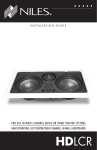
Figure 1
The illustration shows how a
typical CM loudspeaker
mounts into a ceiling.
Installation Considerations
Installation Considerations
New Construction Bracket serves as a
“hole saver” when drywall has not
been applied. It is not necessary when
retrofitting to existing ceilings.
Knockout wire tie allows the wire to be
secured to the bracket throughout the
new construction process. It knocks
out cleanly when the speaker is
installed.
New construction wings
instantly snap into the
bracket without screws.
Dogs swivel 90°, then
clamp the speaker
frame to the drywall.
Frames are molded with a
slight texture to assure
good paint adhesion.
Wings are scored for
easy size trimming.
Mounting screws tighten the
“dogs”, clamping the speaker
to the drywall.
Brackets and wings
attach to the ceiling joists
with nails or screws.
Rust-proof aluminum grilles make the CM
series perfect for moist environments.
Figure 2
The CM5PR and
CM6PR include
easy access, baffle
mounted tone
controls that enable
you to accommodate varying room
acoustics
19
Figure 3
20°
The CM5PR and
CM6PR tweeter is
housed in a custom
designed, low
diffraction enclosure,
pivots up to 20° to
provide optimum
high frequency
coverage
4
Plan to wire the system so that each pair
of speakers has its own volume control
built into the wall (think of a volume control as a dimmer switch for sound).
Niles makes a wide range of high performance indoor and outdoor volume controls. They are available in Standard or
Decora® style cover plates (just like your
light switches and dimmers). Volume controls are connected in line with the speaker, so you must connect the wire from the
amplifier to the volume control and then
from the volume control to the speaker.
Speaker Wire
Use 2-conductor speaker wire when connecting CM5PR and CM6PR speakers to
your receiver or amplifier. For most applications, we recommend you use 16 or 18
gauge stranded wire. For wiring runs
longer than 80 feet we recommend 14
gauge stranded wire. The no-strip terminals of the PR speakers will accommodate
12 to 18 gauge wire.
When you run wire inside walls, special
jacketing (CL-2 or CL-3) is required to
both protect the wire and for fire prevention. In some areas conduit is required.
For a trouble-free installation, low voltage
wire such as speaker wire must be run in
accordance with the National Electrical
Code and any applicable provisions of the
local building code. If you are unsure of
the correct installation techniques, wire
jacket or type of conduit to use, consult a
TECH TIP
Wire size is expressed by
its AWG (American Wire
Gauge) number. The lower
the number, the larger the
wire, i.e. 12 AWG is physically larger than 14 AWG.
5
professional audio/video installer, your
building contractor, or the local building
and inspection department.
Incorporating Remote Control
If your stereo system operates with a wireless Infrared (IR) remote control, consider
the advantages of installing a Niles Infrared
Extender System. Niles manufactures a
number of concealable IR sensors and wall
mounted keypads which send a copy of
your hand-held remote command via a
wire to your main equipment location,
where it is repeated to your stereo system.
The wire is typically installed with the
speaker wire, since the speaker signal and
the IR signal will not interfere with each
other. This makes almost no difference to
the installation time, and the cost of the
recommended IR control cable (West Penn
D291 or equivalent) is reasonable.
The correct routing for IR control cable is
to home run an IR control cable from the
main equipment location beside the
speaker wire to the planned volume control location; and then on to the proposed
sensor location. The combination of IR
control cable and speaker wire enables a
programmable Niles IntelliPad ® to be
installed at a later date (the IntelliPad has a
convenient speaker mute feature in addition to automating and controlling your
stereo system). An IR sensor is best placed
where it is convenient for you to point the
hand-held remote. Both an IntelliPad and
an IR sensor can be connected in one
room with one home run IR control cable.
Insulation Behind The Speaker
For best performance from your speakers
lay a batten of fiberglass insulation
(example: R-19 un-batted insulation) on
top of the speaker. Try to keep the same
amount of insulation for each speaker,
particularly in the same room, for consistent bass response.
Specifications
CM5PR
CM6PR
Driver Compliment
Driver Compliment
5-1/4" talc-filled polypropylene woofer
with butyl-rubber surround
6-1/2" talc-filled polypropylene woofer
with butyl-rubber surround
3/4" fluid-cooled ultra-wide dispersion
Kaladex® tweeter in a custom pivoting
coaxial enclosure
3/4” fluid-cooled ultra-wide dispersion
Kaladex® tweeter in a custom pivoting
coaxial enclosure
Recommended Amplifier Power
Recommended Amplifier Power
10 to 100 watts per channel
10 to 125 watts per channel
Nominal Impedance
Nominal Impedance
4 or 8 ohm selectable
4 or 8 ohm selectable
Frequency Response
Frequency Response
65Hz to 20kHz, +/- 3dB (on axis)
60Hz to 20kHz, +/- 3dB (on axis)
Tweeter Adjustment
Tweeter Adjustment
Up to 20° pivot angle
Up to 20° pivot angle
Sensitivity
Sensitivity
88dB for 2.83 volts of Pink Noise
89dB for 2.83 volts of Pink Noise
Overall Exterior Frame Dimensions
Overall Exterior Frame Dimensions
8-1/8" diameter
9-1/4" diameter
Depth Behind Wall
Depth Behind Wall
3-3/8" deep (based on 1/2" drywall)
3-3/4" deep (based on 1/2" drywall)
Wall Cut-Out Dimensions
Wall Cut-Out Dimensions
6-7/8" diameter
8" diameter
Wiring Requirements
Wiring Requirements
We recommend 16 to 18 gauge stranded
wire for up to 80 feet, 14 gauge stranded
wire for up to two hundred feet.
We recommend 16 to 18 gauge stranded
wire for up to 80 feet, 14 gauge stranded
wire for up to two hundred feet.
Connectors accommodate 12 to 18 gauge
stranded wire.
Connectors accommodate 12 to 18 gauge
stranded wire.
Specifications
Installation Considerations
Incorporating a Local Volume Control
In a multiroom system there is one indispensible device for true convenience—a
local volume control. It enables you to
adjust the volume of the speakers without
leaving the room.
18
Speaker Placement
Listening at Higher Volumes
It requires more power to achieve a reasonable volume of sound in a large room than
it does in a small room. It is possible (even if
you are not a teenager) to turn the volume
so high that the amplifier runs out of power.
This creates “clipping” distortion.
Introduction
Although the CM5PR and CM6PR have
extensive ability to compensate for unusual placements with their unique pivoting
tweeters and acoustic fine-tuning switches; placement is still the primary tool for
satisfying your particular listening needs.
In the following section, we discuss how
speakers should be placed and how tweeters should be directed and how the
acoustic fine-tuning switches should be set
for different purposes.
Clipping distortion makes treble sound
very harsh and unmusical. When you hear
harsh sounding treble from any good
speaker, turn the volume down immediately! Those harsh sounds are masking
some much more powerful ultra-high-frequency sound spikes which will quickly
damage any fine loudspeaker. You are
much less likely to damage a speaker with
a large amplifier because it will be very
loud indeed before it produces any clipping distortion.
Cleaning
You can clean the speaker with a dampened soft cloth or paper towel. If the
speaker is mounted high up on a wall or
ceiling, use a broom to gently brush it off.
Placement for Critical Listening
If you like to imagine that the band or
orchestra is playing in front of you as you
listen to music, or you are very conscious
of clarity, detail and the textures of the
individual instruments, or you listen critically to movie soundtracks or music
videos in your home theater, you will
need your speakers placed so that they are
optimized for critical listening. Here are
some guidelines to make the process of
placement quick and easy.
Make sure the sound will not be blocked
or reflected off of furniture or other
objects. You should have a direct line of
sight with the front of the speaker. To
determine the best position, measure the
“listening” distance between the ideal listening position (your favorite chair or
couch) and the location in which you plan
to install the speakers. Try to place the
speakers so that they are equally distant
from your listening spot and at least one
half of the listening distance apart (this
maintains a large pleasant stereo “image”).
In home theater applications where there
is a center channel you may choose to
space the left and right main speakers farther apart for a “bigger than life” sound
with Dolby ® encoded movies and TV
shows. However, for combined music and
movie usage stay within the good placement zone for music. For example; if you
are ten feet back from the speakers, the
speakers should be between five and ten
feet apart (See Figure 4).
Speaker Placement
Operations
Operation
Tweeters should be directed at the listening position.
Figure 4
In this example,
the speakers
could be
placed from
five to 10 feet
apart, since the
listener is 10
feet back from
the speakers
Direct tweeter
towards listener
Critical
Listening
Position
10'
5'
10'
Direct tweeter
towards listener
17
6
ent or “all around you” effect). The speakers can be placed near corners to create
more reflected sound. By directing the
tweeters to point away from the listener,
so they create as much reflected sound as
possible, you emphasize the ambient
effect. The more reflected sound there is
in the room the stronger the ambient
effect at low volumes. You should use
moderation, however, otherwise the compromise becomes too one sided and at
high volumes, the sound will be blurred
and less distinct.
The rule of thumb is to add one pair of
speakers for every 100 to 200 square feet
of listening area. Curiously, this is not so
that you can play the music louder, but so
that you can play it softer! When you
have only one pair of speakers in a large
room you will notice that when the sound
is perfect in one part of the room, it is too
loud near the speakers. By placing more
than one pair in the room you will avoid
these “hot spots” of loud sound and you
will create more sonic ambiance while
maintaining clarity and a rich sound
everywhere (See Figure 5).
Placement for Home Theater
Rear Applications
In a home theater, the goal is to reproduce
the experience of a great movie theater in
our homes. The biggest difference
between the two is the rear or surround
speaker array in a commercial theater.
Here, it is not uncommon to see twenty or
thirty speakers around the audience. This
huge array of speakers assures that you
will feel completely surrounded by the
ambient soundtrack of the movie. Film
makers try to use the “surround” soundtrack to envelope you in the environment
on screen. They will place background
music, rain sounds, traffic noise, etc. on
the “surround” soundtrack. In a home
with a single pair of speakers it is easy for
the jungle sounds to sound like they are
“in the middle of your head” just like
headphones!
You can make listener position still less
critical by using mono rather than stereo.
This can be difficult to achieve with normal stereo amplifiers. However, Niles
manufactures Systems Integration
Amplifiers® which enable one room to be
wired in stereo while other rooms are
wired in mono! Consult your local Niles
dealer for more information.
In smaller rooms or rooms that are infrequently used, you typically can’t justify
the expense of more than two speakers.
Try to bracket the room with the two
speakers. Diagonal placement is a very
effective way to stretch the coverage pattern of two speakers. You can also compromise between direct sound (for detail
and clarity) and reflected sound (the ambi-
7
A single pair of CM5PR or CM6PR
Loudspeakers, properly placed, can create
a very convincing simulation of an array
of speakers. If you place them near a hard
reflecting surface you can make one pair
of speakers sound like several. Create as
many reflections as possible by placing
the speakers near a corner so that the
adjoining walls will act as a powerful
reflector. Direct the tweeters so that sound
is pointed away form the listener creating
results will be obtained by using a spray
gun or airless sprayer, thinning the paint
(prevents clogging of the grille holes), and
by applying several light coats instead of
one heavy one.
Figure 17
Tightening the
mounting “dogs”
9. Setting the Bass and Treble cut switches. Listen to a well-recorded piece of
music at the user’s favorite listening
position. a) Listen for bass boominess,
particularly when the speaker is placed
near a corner. Use the -2dB Bass cut to
correct. b) Listen for treble harshness or
ringing, particularly when the speakers are
placed in a room without carpet/ Use the
-2dB Treble cut switch to correct.
10.Install the grille into the speaker. The
grilles should fit snugly. If you have difficulty fitting them in, try loosening the
mounting dog screws (excessive tightening can distort the shape of the frame
holding the grille in place).
Painting the Speakers
All models may be painted. The plastic
will readily accept most paints.
The speakers must be masked prior to
painting them. The inside circular portion
of the hole template can be used as a
paint mask. Remove the outside portion of
the template by gently pulling along the
perforation. Affix the mask to the front of
the speaker using a piece of tape. Fold the
tape onto itself to form a double-sided
loop. Affix the tape to the tweeter and
place the mask onto the speaker.
The grilles should be painted before they
are installed. For all models, the best
Speaker Phase
Speaker wire has two conductors. One
conductor is attached to the negative (-)
terminals and one conductor is attached
to the positive (+) terminals of both your
speaker and your amplifier. Usually, the
wire is marked for your convenience.
There are different ways wires are marked:
a stripe on one wire, a ribbed area of one
conductor you can only feel, different colors of metal wire on each conductor, or
there might be a fabric strand or string
wound into one of the conductors. Of
course, there are some wires which
appear completely identical. Be careful, or
you might make a mistake.
If you make a mistake, one speaker will be
playing “out-of-phase” with the other
speaker. An out-of-phase pair of speakers
work against each other and the sound of
the two speakers playing together will be
lacking in bass and be “phasey” sounding.
If you suspect the sound is not right and
you cannot see any markings on the wire,
try this simple test:
Final Installation in New or Existing Construction
Speaker Placement
Placement for Varying
Listening Positions
If you want the freedom to sit anywhere in
a room facing any direction, and/or find
that you prefer the “all around you” sound
of some car stereos to a conventional
“sound stage” facing you, consider the
speaker placement techniques professional installers use in restaurants and bars.
They place speakers in an array around
the listening area, so that the music is
always surrounding you, regardless of the
direction you face.
1. Stand half way between the speakers.
2. Play some music with the amplifier
or radio set to Mono.
3. Listen to the richness of the bass and
the loudness of the sound.
4. Turn off the amplifier and reverse the
connections on one amplifier channel only.
5. Repeat the listening test with the
same setting of the volume control.
When the sound has a richer bass
and is slightly louder the speakers are
working together or “in-phase”.
16
1. If it is possible to lay a batt of insulation
into the ceiling cavity do so. Remember
to use equal amounts of insulation for
each speaker.
2. Check the position of the Impedance
Jumper on the crossover PC board.
Choose the 4 ohm position if you are
using an amplifier capable of drawing a
4 ohm load and you have only one pair
of speakers connected. Otherwise, use
the 8 ohm position (See Figure 15).
3. Separate the speaker wire so that at least
two inches of each conductor are free.
7. On both models, there are four clamps
or mounting “dogs” which hold each
speaker in place. The dogs are tightened via four front-baffle screws. To
install the speaker, first rotate the dogs
inward. Insert the speaker into the
cutout and tighten the dogs by turning
the screws clockwise. DO NOT OVERTIGHTEN THESE SCREWS. Over-tightening the clamps may make the grille
difficult to install. (See Figure 17).
4. Open the no-strip terminal by applying
pressure to the red and black levers until
an audible “click” is heard.
NOTE: The screws will be easier to turn if
you “prime” them first. Before installing each
speaker, turn the screws in and then turn
them back out to their original positions.
5. Insert one unstripped wire fully into the
black and one into the red terminal. Pay
attention to the markings on the wire.
Each speaker must be connected to the
amplifier in the same way. If unsure,
see “Speaker Phase” located on the following page. Squeeze the red and black
levers until they click signifying that
they have locked into the wire. Check
to make sure that the knife assembly
inside the no strip connector has properly pierced the wire (See Figure 16).
8. Direct the Tweeter. The tweeter is
directed by gently pushing on the edge
of the tweeter grille. It will move 20° in
any direction. For critical listening point
the tweeter to the user’s favorite listening position minimizing reflections from
the side walls. For surround sound or
low volume background listening create more reflections and thus more
ambience by directing the tweeter
towards the side walls. See Speaker
Placement on Page 6.
Figure 15 Setting the Impedance Jumper.
15
6. Insert the no strip terminal into the
corresponding socket on the rear of
the speaker. Push it down until it locks
in place. The terminal will only fit in
the socket in one direction. If the terminal does not properly seat, reverse
the terminal
still more reflections and thus more “surround sound” effect. However, as you
move the speaker farther away from the
listener, both the reflected and the direct
sound will dissipate, requiring more
power from your surround sound amplifier
channels. If the surround sound system
you are using has a small five or ten watt
amplifier for the rear speakers, stay within
five to eight feet of the listening location. If
you are using a 25 to 50 watt amplifier
you can mount the speakers 10 to 15 feet
away from the listening location and still
achieve reasonably high volume levels.
In large or unusually shaped rooms, using
multiple speakers might be the only way to
achieve a good effect. In large or unusually shaped rooms this might be the only
way to achieve a good effect. If you like
to listen to music surround modes which
emulate concert hall acoustics, more than
two surround speakers will prove extraordinarily effective (See Figure 6). With
Niles CM5PR and CM6PR loudspeakers it
is easy to add another pair without affecting the decor of the room. However, you
will need to use a much more powerful
amplifier than that which is built into a
typical surround sound receiver or amplifier. Niles makes a number of Systems
Integration Amplifiers with proprietary
features that make them uniquely suited
to enhance a good surround sound system. Consult your local Niles dealer for
more information.
The Boundary Effect
Corners can affect the bass response of the
speaker powerfully! This is called the
boundary effect. You will emphasize particular bass frequencies and cancel out
other bass frequencies when you place
speakers close to the wall/ceiling boundary or a corner wall boundary. This can
make the speaker sound excessively
boomy and inaccurate to some listeners,
while to others it just seems like more bass
sound. A good rule of thumb is if you
always listen to your current pair of speakers with the bass turned up, you’ll enjoy
corner placement. If you keep your tone
controls at neutral, try to keep the speakers at least two or three feet from the
boundaries of the room.
Figure 5
Figure 6
Varying Listening Position
Surround Sound
Speaker Placement
Final Installation in New or Existing Construction
Final Installation in New
or Existing Construction
Figure 16 No-Strip Speaker Wire Terminal.
8
Running the Speaker Wire in New
Construction
If you have doubts about whether you are
capable of installing a Niles ceiling mount
loudspeakers, consult a Niles dealer or
professional installer. They have special
tools, techniques, and experience to make
the impossible possible. The installer can
provide you with an estimate before any
work is done.
Scheduling and Preparation
Plan to schedule the speaker wiring after
the electrical wiring is finished. That way
you can avoid wire routes which could
potentially induce hum over the speaker
wire. The basic rules are:
• Never run speaker wire through the
same hole as an electrical cable.
• Never run speaker wire into the same
J-box as electrical cable.
• Avoid running the speaker wire beside
the electrical cable. Keep your speaker
cable at a distance of at least 18"-22"
from any electrical power cable.
Figure 7
Side-by-side wiring is unavoidable in particular spots in every house, just move the
speaker wire route away as soon as possible. If construction forces a side by side
run for more than ten feet, install metal
conduit or shielded speaker wire. Lowvoltage wires such as doorbells, intercoms, telephone, security, or television
cannot cause interference or hum on your
speaker wires, so you can safely run all of
them at the same time, through the same
holes, side-by-side.
Before you drill any holes, mount the
speaker brackets in the desired speaker
locations and mount p-rings or open
backed J-boxes where the in-wall volume
controls and stereo equipment will be.
Safety First!
Wear gloves, safety goggles and head protection when drilling. Avoid nails, they ruin
bits and they can create injury. Pay particular care when using “hole-hogs” and other
powerful electric drills; the torque of the
drill when suddenly stopped by a nail can
break the wrist of a strong man.
Drilling
Use a bit that is large enough for the wires
you plan to run. An auger bit is the preferred bit for rough-in wiring. It will actually pull itself through the wood, so that
the drill motor, not you, does most of the
work. You may be drilling a lot of holes,
so this is an important consideration.
Always drill the holes in the center of the
stud. If you have to notch the stud or drill
the hole closer than one inch from the
edge of the stud, protect the wire with a
nail plate (See Figure 7).
When drilling holes in ceiling joists drill
in the center of the joists and try to locate
the hole near the end of the joist. DO
NOT drill through a “gluelam” or any
load bearing beam without the direction
of your contractor.
9
Installation in
Existing Construction
Figure 14
IMPORTANT: Before you cut into any
wall, review the sections on running
wire and speaker placement.
1. When determining the location of the
speaker cutout keep in mind that the
mounting dogs will extend 3/4" beyond
the cutout. make sure that you do not
place the edge of the cutout directly
next to a ceiling joist. Locate the joists
using a stud sensor or hand-knocking.
2. Once you have determined a possible
position for the cutout, drill a 1/8” pilot
hole just barely through the ceiling
(1/2” to 5/8” deep in most homes)
about an inch below the center of your
proposed speaker location. BE VERY
CAREFUL NOT TO DRILL THROUGH
EXISTING WIRES, PIPES, OR STRUCTURE. IF YOU FEEL ANY EXTRA RESISTANCE AS YOU ARE DRILLING, STOP.
3. Cut a foot-long piece of coat hanger.
Bend the wire (creating a right angle)
leaving 4-1/8" at one end for the
CM5PR and 4/3/4" for the CM6PR (this
allows for the extra width of the mounting dogs). Poke the “L-shaped” wire
into the pilot hole and turn it in a complete circle and move it into the ceiling
cavity to make sure you have approximately 3-3/4" of depth. If the wires
movement is obstructed by anything, fill
the hole(s) with spackle and try another
location. (See Figure 14)
4. If the coat hanger moves freely in a complete circle, hold the supplied template
up to the ceiling surface. Outline the circular cutout on the ceiling surface with a
pencil. Drill starting point with a 1/4" bit.
5. If you are cutting drywall use a
sheetrock or keyhole saw. Cut the hole
with the saw at a 45° angle. That way,
the drywall section can be replaced
cleanly if there is an unseen obstruction
behind the wall. BE VERY CAREFUL
NOT TO SAW THROUGH EXISTING
WIRES, PIPES, OR STRUCTURE. IF
YOU FEEL EXTRA RESISTANCE AS
YOU ARE CUTTING, STOP.
Installation in Existing Construction
Installation Fundamentals
Installation
Fundamentals
6. If you are cutting into a plaster ceiling,
use masking tape to outline your penciled circle and use a razor to score the
plaster down to the lath beneath. Then
use a chisel to remove all of the plaster
within the taped outline. To actually cut
the lathe, two methods are used professionally; sawing with a metal cutting
blade on a sabre saw is the quickest
and the riskiest. Sawing a lathe with a
sabre saw can easily vibrate plaster off
the ceiling in a completely distant location creating more patchwork. If you
have the patience, use a pair of tin snips
to slowly nip away at the lath instead.
There is little risk with this method, it is
just time consuming.
14
Insulating the Wall Cavity
If feasible, fill the wall cavity with insulation at this point.
Mounting The New Construction
Bracket
The hole saving bracket enables a faster
and cleaner final installation of the speaker. It forces the drywall installer to cut out
the speaker hole for you and provides
wire ties for the speaker wire, reducing the
risks of accidental loss or movement of the
wire. In addition, it enables you to align
your speakers with other ceiling fixtures
with great accuracy since you can really
see exactly where the speaker will be.
To install the bracket, first attach the
QuickSnap™ new construction wings to
the bracket by snapping them into the
sides of the bracket. The wings can be
shortened by breaking them along the
scored lines if the length will interfere with
corner or eaves.
Figure 12
The optional hole saving brackets are installed
and the speaker wire is attached to the bracket.
13
The wings and brackets have centering
lines to simplify placement of the speakers.
Screw one side of the assembled bracket
with wings to the joist using one of the
supplied screws. Level the bracket. Screw
the other side of the bracket/wing assembly to the joist. Two screws on each side
make for a very secure installation. Secure
the wire to the bracket using bracket’s
wire tie. The drywall installers will cut the
drywall to the exact size of the bracket.
(See Figure 12)
Concealing Speaker Wire for a
Future Installation
Attach the speaker wire in a loop between
the ceiling joists and carefully mark the
exact location of the wire on a set of
plans. Ask the general contractor to inform
the drywall installers that the speaker wire
loops are concealed for future installations. (See Figure13)
Figure 13
The speaker wire is looped and hung on two
nail attached to the joists securing it for
future use. Make sure the location is noted
on house plans.
Try to line the holes up perfectly, because
it makes pulling the wire much easier. A
good technique is to snap a chalk line
across the face of the studs or against the
bottom of the ceiling joists. Then work
backward so that you can always see the
holes you have already drilled. Paying
careful attention to this will save you a lot
of time later on!
Pulling the Cable
Pull the cable in sections (from the stereo
to the volume control, from the volume
control to the speaker). Start with the
longest sections and use left over wire to
complete the short sections. If you plan to
pull many rooms at the same time through
a central route, walk off the distance to
each destination, add a generous fudge
factor for turns and other obstacles, then
cut off each section so that you have a
bundle of wires you can pull at once.
Whenever you run the wire further than
four and one half feet from a hole in a stud
or joist (open attic space, going up walls,
etc.), fasten the wire to the joists or studs
using cable clamps or appropriately sized
wire staples. The wire should not have
large sags in it, nor should it be too tight.
Try to protect the wire from being stepped
on in attics or other unfinished crawl
spaces. There are guard strips, raceways
and conduits which can be used to protect
the cable. Consult the local building code
for special requirements in your area.
Concealing Speaker Wire
in Existing Walls
This is actually a fairly simple task if you
restrict your choice of speaker locations
and wire routes to the interior walls or
ceilings of your home. Interior walls in
almost all North American residences are
hollow, so that it is easy to flush mount
speakers into them and route new speaker
cable around the house. What you see
when you look at the painted wall board,
plaster, or paneling is only the skin of the
wall. Behind the skin is the skeleton; twoby-four wood or metal “studs” running
vertically from the floor to the ceiling in
walls and two-by-six or larger “joists” running horizontally in the ceilings and
floors. In between the studs and the joists
is the space for the wiring and plumbing
of your home.
Exterior walls are different. They must
insulate the house from the heat and cold
outside, so they are stuffed with insulation.
The national building code requires that
the hollow wall space in exterior walls be
broken by a horizontal stud placed
between the vertical studs. This “fire
blocking” makes it very difficult to retrofit
long lengths of wire. In some areas of the
country the exterior walls are constructed
of solid masonry, and have no hollow
space for speakers or wires.
Installation Fundamentals
Installation in New Construction
Installation in New
Construction
Start by examining all the possible routes
you might take to run the speaker wire
from the speaker to the volume control
and back to the stereo. Use a stud sensor
or other device to locate the internal structure of the wall. You want to avoid all
studs or joists. A typical route would be:
from the speaker location in the ceiling,
across the attic, then down through a top
plate (the horizontal 2x4 or 2x6 laid
across the vertical studs) to the volume
control location, back up to the attic,
across the attic, and finally down another
wall plate to a J-Box in the wall behind the
stereo system itself (See Figure 8).
Identify where all of your electrical,
phone, and TV wiring is likely to be and
plan to route around it all. You can accidentally induce 60Hz hum on your speakers if you run your speaker wire right
beside electrical wire for more than a few
feet. Try to keep speaker wire running par-
10
Volume
Control
Location
Stereo
Location
Figure 8
allel to power cables at least three feet
away. To find exactly where an electrical
cable is routed, try inspecting the inside of
the wall by turning off the breaker for a
particular power outlet or switch, removing the cover plate and switch or receptacle, and shining a penlight into the wall. If
you have access to an attic or basement
space you can quickly see which part of
the wall space is free of obstructions (See
Figure 9).
If your house is built on a
slab or you are wiring
between two finished floors,
look for baseboards which
could be removed and
replaced with the wire
behind them. Doorjambs can
be removed and often have
enough space for speaker wire all the way
around the door (See Figure10).
In traditional wood stud/drywall construction you should first cut the hole for the
speaker and utilize the large hole to auger
across the (through the ceiling joists) for as
far as your drill bit will take you.
Sometimes, you will need to use the
“notching” technique to reach areas your
drill bit won’t reach or to turn corners (e.g.
to go down the wall when there is not an
accessible attic). Don’t make an irregular
hole in the drywall. If you carefully cut a
rectangular hatch in the drywall you will
make your patch at the same time you cut
your hole. Notch the bottom of the joists
and run the wire through the notches.
Protect the wire with nail plates. Once
you’ve run your wire replace the hatch you
cut using standard drywall “joint tape” and
“joint compound” to hold the patch in
place, let dry, sand surface and touch-up
the wall with paint. (See Figure 11).
Figure 10
Installation Fundamentals
Installation Fundamentals
Speaker
Location
When you don’t have access
above or below the wall, try
to estimate the existing wire
and pipe locations from the
positions of electrical outlets
and plumbed fixtures on both
sides of the wall. Take a look
at the outside of your house
too, sometimes conduit,
vents or drain pipe will be
visible that give useful information. Choose the route
with the fewest potential
obstacles.
The door jamb has been removed and the
speaker wire concealed between the wall and
the jamb. Nail plates are installed to protect
the wire and the door jamb is replaced
Sometimes, an under-the-carpet run is
possible (there are special flat speaker
wires made for under-the-rug wire runs).
As a last resort, heating and air conditioning vents can be used as wire raceways for
plenum rated wire (check your local
building codes, some municipalities
require conduit).
Unobstructed space
for speaker wiring
Figure 9
Figure 11 Diagram of ceiling speaker cut-out with ceiling joists notched for wire run.
11
12