1
NTI
NETWORK
Tel:330-562-7070
TECHNOLOGIES 1275 Danner Dr
Fax:330-562-1999
Aurora,
OH
44202
INCORPORATED
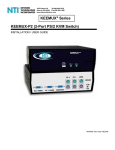
KEEMUX-P2 (2-Port PS/2 KVM Switch)
INSTALLATION / USER GUIDE
MAN049 Rev 8-28-01
PS/2
NTI
NETWORK
TECHNOLOGIES
INCORPORATED
KEEMUX-P2
PS/2
CPU
SELECT
1
CPU 1 CPU 2
TABLE OF CONTENTS
I n t r o d u c t i o n ......................................................................................... 2
Materials
Materials Supplied............................................................................ 2
Materials NOT supplied but required................................................ 2
I n s t a l l a t i o n ........................................................................................... 2
Using the NTI Switch
Front Panel Control........................................................................... 2
Keyboard Control.............................................................................. 2
S C A N M O D E ........................................................................................ 2
B R O A D C A S T M O D E ........................................................................... 2
K e y b o a r d F e a t u r e s .............................................................................. 3
K E E M U X - P 2 R e m o t e S p e c i f i c a t i o n s ..........................................
3
T r o u b l e s h o o t i n g .................................................................................. 3
W a r r a n t y I n f o r m a t i o n .......................................................................... 3
2
INTRODUCTION
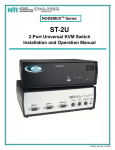
The KEEMUX-P2 switch allows one user to access two PS/2 computers with only one keyboard, monitor and mouse. Internal
auto-boot circuitry allows both computers to boot simultaneously and error-free without the need for a keyboard, monitor and
mouse on each computer.
MATERIALS
Materials Supplied with this kit:
1.
NTI PS/2 KVM Switch
Materials Not Supplied, BUT REQUIRED:
1.
A set of 2 cables for each computer being connected to the switch must be used:
1.
VEXT-x x - M M ( h i g h res) or VINT-x x - M M ( l o w res) for video interface
PS/2 computer to switch
2.
(1) VVKINT-xx-MM for keyboard and mouse interface.
OR
(2) VKINT-xx-MM for keyboard or mouse interface
Materials Not Supplied,
VKINT-1K-1
BUT MAY BE REQUIRED:
Booster Cable for keyboard or mouse interface with Compaq Proliant 2000 and non-Intel
architecture Unix machines with PS/2 ports (such as HP-9000). Two VKINT-1K-1 cables are needed for
each applicable computer.
INSTALLATION
1.
Turn OFF power to all computers that will be connected to the NTI Switch before connecting or disconnecting any cables
WARNING! YO U M A Y D A M A G E Y O U R C O M P U T E R I F Y O U D O N O T T U R N T H E P O W E R OFF BEFORE CONNECTING OR DISCONNECTING CABLES.
2.
3.
4.
5.
Connect PS/2 keyboard to “USER KEYBD” port on rear panel of switch.
Connect PS/2 Mouse to “USER MOUSE” port on rear of switch.
Connect monitor to “MONITOR” port on rear of switch.
Using (1) VVKINT-x x - M M o r ( 2 ) V K I N T - x x - M M o r V K E X T - xx-MM cables (required, not supplied), connect keyboard and
mouse ports of PS/2 computer to “CPU-1 KEYBD” and “CPU-1 MOUSE” ports on rear of switch.
NOTE:
If installing a Compaq Proliant 2000 or a non-Intel architecture Unix machine with PS/2 ports (such as HP-9000), booster cables
may be needed (VKINT-1K-1).
If booster cables are used, they must first be directly connected to both the keyboard and mouse
CPU ports on the switch.
6.
7.
Using VINT-x x - M M o r V E X T - xx-MM (required, not supplied), connect video port of PS/2 computer to “CPU-1 VIDEO” port on
rear of switch.
Repeat steps 5 & 6 for CPU-2.
POWER-UP SEQUENCE
POWER-DOWN SEQUENCE
1. The KEEMUX-P2 is powered by the computers it is connected to.
2. Turn on power to monitor.
3. Turn on power to either or both computer(s).
1.
Power down computers.
USING THE NTI SWITCH
The switch can be operated by the front control panel or by keyboard control.
Front Panel Control
1.
2.
Pressing the touch switch on the front panel will toggle between CPU 1 and CPU 2 and connect the selected computer to the
keyboard, monitor and mouse.
H o l d i n g d o w n t h e " C P U S E L E C T " b u t t o n f o r m o r e t h a n 2 s e c o n d s will cause the switch to cycle through 3 extended modes of
operation: SCAN, BROADCAST, and COMMAND (see Keyboard Control, Scan and Broadcast sections). Release the button
when the desired mode has been selected.
Keyboard Control
To control switch from keyboard, “COMMAND” Mode must be enabled.
To enable "COMMAND" Mode:
“ C T R L ” + “ `” (accent key)
To disable "COMMAND" Mode:
“ESC” or “CTRL” + “`”
"I" or à
To increment port:
"D" or ß
To decrement port:
To select a specific port:
“P01” or “P02”
To enable / disable "BROADCAST" Mode:
"B"
To enable / disable "SCAN" Mode:
"S"
To set the scan dwell time (time in seconds before switching to other port):
" Txxx" (xxx from 002 to 255)
*NOTE: You must exit "COMMAND" Mode in order to type to a computer.
3
SCAN
SCAN Mode is indicated by a flashing CPU port LED. The switch scans to either port with a CPU powered ON. That port remains
active for the configured dwell time (default time is 5 seconds) before switching to the other powered ON CPU port. See Keyboard
Control Section for configuring the scan dwell time.
NOTE: The keyboard and mouse must remain idle for the full SCAN dwell time before the switch selects the other port.
B R O A D C A S T (use with extreme caution)
BROADCAST Mode is indicated when both CPU LED’s are illuminated. This mode allows the operator to send keystrokes to both
active computers simultaneously. However, BROADCAST Mode has some critical requirements:
1.
BROADCAST Mode must be off when booting and attached computer.
2.
C O M M A N D M o d e m u s t b e O F F f o r keystrokes to reach attached computer when in BROADCAST.
KEYBOARD FEATURES
The keyboard configuration of each computer is saved in the NTI Switch. For example, if the computer attached to Port 2 had
CAPS LOCK and NUM LOCK selected the last time that computer was accessed, then they will automatically be set when that
computer is accessed again.
KEEMUX-P2 REMOTE SPECIFICATON (RMT-2-ST)
5 DIN
SIGNAL
1
LED1
2
LED2
3
SWT
4
GND
5
PWR
Low= < .4 volts High=>
DESCRIPTION
TTL output, low = port 1 selected
TTL output, low = port 2 selected
TTL of contact closure input (10K pullup)
Ground
+5V for LED’’s, limited to 20ma
2.4 volts
Control: When pin 3 (SWT) is brought low for a minimum of 10 MS, and then returned high, the switch will select the other port
(toggle).
TROUBLESHOOTING
1.
2.
3.
4.
Verify all cables are securely connected and that installation procedure was carefully followed.
Verify that power-up sequence was observed.
If a computer seems to be locked up, p r e s s t h e " C P U S E L E C T " b u t t o n a c o u p l e o f t i m e s .
If the problem still persists, unplug the keyboard and mouse cables (not the CPU keyboard and mouse) from KEEMUX-P2
and reconnect them.
5.
If a Compaq Proliant 2000 or non-Intel architecture Unix machine with PS/2 ports (such as HP-9000) does not detect a keyboard or
mouse attached when booting, booster cables (VKINT-1K-1) may be needed for both the keyboard and mouse CPU ports.
See
note under "INSTALLATION" on page 3 for proper installation instruction.
WARRANTY INFORMATION
The warranty period on this product (parts and labor) is one (1) year from the date of purchase. Please contact Network
Technologies Inc at (800) 742-8324 ( 8 0 0 - R G B - T E C H ) o r (330) 562-7070 or visit our website at http://www.nti1.com for information
regarding repairs and/or returns. A return authorization number is required for all repairs/returns.
COPYRIGHT
Copyright© 2001 by Network Technologies Inc. All rights reserved. No part of this publication may be reproduced, stored in a
retrieval system, or transmitted, in any form or by any means, electronic, mechanical, photocopying, recording, or otherwise,
without the prior written consent of Network Technologies Inc, 1275 Danner Drive, Aurora, OH 44202
CHANGES
The material in this guide is for information only and is subject to change without notice. Network Technologies Inc reserves the
right to make changes in the product design without reservation and without notification to its users.
SERIAL NO.:
DATE:
INSPECTED BY:
o
KEEMUX-P2
4