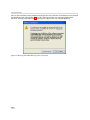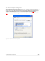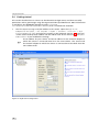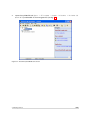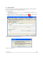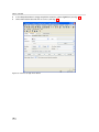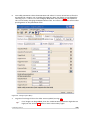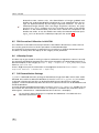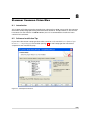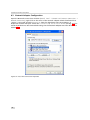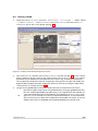
1
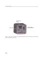
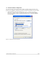
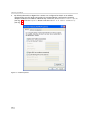
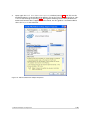
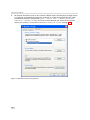
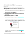
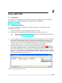
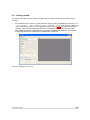
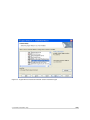
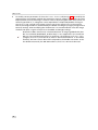
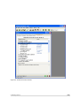
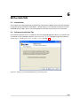
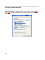
User Manual
Gigabit Ethernet Vision
Quick Start Guide
MAN051 11/2011 V1.0
All information provided in this manual is believed to be accurate and reliable. No
responsibility is assumed by Photonfocus AG for its use. Photonfocus AG reserves the right to
make changes to this information without notice.
Reproduction of this manual in whole or in part, by any means, is prohibited without prior
permission having been obtained from Photonfocus AG.
1
2
Contents
1 How to get started
1.1 Introduction . . . . . . . . . . . . . . . . . . . . . .
1.2 Hardware Installation . . . . . . . . . . . . . . . . .
1.3 Network Adapter Configuration . . . . . . . . . .
1.4 Software for Photonfocus GigE Cameras . . . . . .
1.5 Additional Software Installation for DR1 Cameras
.
.
.
.
.
.
.
.
.
.
.
.
.
.
.
.
.
.
.
.
.
.
.
.
.
.
.
.
.
.
.
.
.
.
.
.
.
.
.
.
.
.
.
.
.
.
.
.
.
.
.
.
.
.
.
.
.
.
.
.
.
.
.
.
.
.
.
.
.
.
.
.
.
.
.
.
.
.
.
.
.
.
.
.
.
.
.
.
.
.
5
. 5
. 5
. 7
. 11
. 11
2 Pleora eBUS SDK
2.1 Introduction . . . . . . . . . . . . . . . . . . . . . . . .
2.2 Software Installation . . . . . . . . . . . . . . . . . . .
2.3 Network Adapter Configuration for Pleora eBUS SDK
2.4 Getting started . . . . . . . . . . . . . . . . . . . . . .
2.5 Width setting in DR1-D1312(IE) cameras . . . . . . . .
.
.
.
.
.
.
.
.
.
.
.
.
.
.
.
.
.
.
.
.
.
.
.
.
.
.
.
.
.
.
.
.
.
.
.
.
.
.
.
.
.
.
.
.
.
.
.
.
.
.
.
.
.
.
.
.
.
.
.
.
.
.
.
.
.
.
.
.
.
.
.
.
.
.
.
.
.
.
.
.
.
.
.
.
.
.
.
.
.
.
13
13
13
14
15
19
3 Cognex VisionPro
3.1 Introduction . . . . . . . . . . . . . . . . . . . . . . . . . . . .
3.2 Software Installation Tips . . . . . . . . . . . . . . . . . . . .
3.3 Network Adapter Configuration . . . . . . . . . . . . . . . .
3.4 Getting started . . . . . . . . . . . . . . . . . . . . . . . . . .
3.5 Modifying Basic Parameters in VisionPro QuickBuild . . . . .
3.6 Modifying All Camera Parameters in VisionPro QuickBuild .
3.7 Modifying Camera Parameters in Custom Properties Dialog
.
.
.
.
.
.
.
.
.
.
.
.
.
.
.
.
.
.
.
.
.
.
.
.
.
.
.
.
.
.
.
.
.
.
.
.
.
.
.
.
.
.
.
.
.
.
.
.
.
.
.
.
.
.
.
.
.
.
.
.
.
.
.
.
.
.
.
.
.
.
.
.
.
.
.
.
.
.
.
.
.
.
.
.
.
.
.
.
.
.
.
.
.
.
.
.
.
.
21
21
21
25
26
29
30
31
4 Mathworks Matlab
4.1 Introduction . . . . . . . . . . . .
4.2 Software Installation Tips . . . .
4.3 Network Adapter Configuration
4.4 Getting started . . . . . . . . . .
.
.
.
.
.
.
.
.
.
.
.
.
.
.
.
.
.
.
.
.
.
.
.
.
.
.
.
.
.
.
.
.
.
.
.
.
.
.
.
.
.
.
.
.
.
.
.
.
.
.
.
.
.
.
.
.
.
.
.
.
.
.
.
.
.
.
.
.
.
.
.
.
.
.
.
.
.
.
.
.
.
.
.
.
.
.
.
.
.
.
.
.
.
.
.
.
.
.
.
.
.
.
.
.
.
.
.
.
.
.
.
.
.
.
.
.
.
.
.
.
33
33
33
34
35
5 Matrox MIL
5.1 Introduction . . . . . . . . . . . .
5.2 Software Installation Tips . . . .
5.3 Network Adapter Configuration
5.4 Getting started . . . . . . . . . .
.
.
.
.
.
.
.
.
.
.
.
.
.
.
.
.
.
.
.
.
.
.
.
.
.
.
.
.
.
.
.
.
.
.
.
.
.
.
.
.
.
.
.
.
.
.
.
.
.
.
.
.
.
.
.
.
.
.
.
.
.
.
.
.
.
.
.
.
.
.
.
.
.
.
.
.
.
.
.
.
.
.
.
.
.
.
.
.
.
.
.
.
.
.
.
.
.
.
.
.
.
.
.
.
.
.
.
.
.
.
.
.
.
.
.
.
.
.
.
.
37
37
37
38
39
6 MVTec HALCON
6.1 Introduction . . . . . . . . . . . . . . .
6.2 Software Installation Tips . . . . . . .
6.3 Network Adapter Configuration . . .
6.4 Getting started . . . . . . . . . . . . .
6.5 FPN Correction Calibration in HALCON
6.6 HDevelop Scripts . . . . . . . . . . . . .
6.7 DR1 Demodulation Package . . . . . .
.
.
.
.
.
.
.
.
.
.
.
.
.
.
.
.
.
.
.
.
.
.
.
.
.
.
.
.
.
.
.
.
.
.
.
.
.
.
.
.
.
.
.
.
.
.
.
.
.
.
.
.
.
.
.
.
.
.
.
.
.
.
.
.
.
.
.
.
.
.
.
.
.
.
.
.
.
.
.
.
.
.
.
.
.
.
.
.
.
.
.
.
.
.
.
.
.
.
.
.
.
.
.
.
.
.
.
.
.
.
.
.
.
.
.
.
.
.
.
.
.
.
.
.
.
.
.
.
.
.
.
.
.
.
.
.
.
.
.
.
.
.
.
.
.
.
.
.
.
.
.
.
.
.
.
.
.
.
.
.
.
.
.
.
.
.
.
.
.
.
.
.
.
.
.
.
.
.
.
.
.
.
.
.
.
.
.
.
.
45
45
45
46
47
50
50
50
CONTENTS
.
.
.
.
.
3
CONTENTS
7 National Instruments Measurement & Automation
7.1 Introduction . . . . . . . . . . . . . . . . . . . .
7.2 Software Installation Tips . . . . . . . . . . . .
7.3 Network Adapter Configuration . . . . . . . .
7.4 Getting started . . . . . . . . . . . . . . . . . .
.
.
.
.
.
.
.
.
.
.
.
.
.
.
.
.
.
.
.
.
.
.
.
.
.
.
.
.
.
.
.
.
.
.
.
.
.
.
.
.
.
.
.
.
.
.
.
.
.
.
.
.
.
.
.
.
.
.
.
.
.
.
.
.
.
.
.
.
.
.
.
.
.
.
.
.
.
.
.
.
.
.
.
.
.
.
.
.
51
51
51
52
53
8 Stemmer Common Vision Blox
8.1 Introduction . . . . . . . . . . . .
8.2 Software Installation Tips . . . .
8.3 Network Adapter Configuration
8.4 Getting started . . . . . . . . . .
.
.
.
.
.
.
.
.
.
.
.
.
.
.
.
.
.
.
.
.
.
.
.
.
.
.
.
.
.
.
.
.
.
.
.
.
.
.
.
.
.
.
.
.
.
.
.
.
.
.
.
.
.
.
.
.
.
.
.
.
.
.
.
.
.
.
.
.
.
.
.
.
.
.
.
.
.
.
.
.
.
.
.
.
.
.
.
.
55
55
55
56
57
A Revision History
4
.
.
.
.
.
.
.
.
.
.
.
.
.
.
.
.
.
.
.
.
.
.
.
.
.
.
.
.
.
.
.
.
59
1
How to get started
1.1
Introduction
Photonfocus GigE cameras are fully GigE Vision and GenICam compliant. The cameras can be
run with the Pleora eBUS SDK that can be downloaded from the Photonfocus webpage or with
any other tool that supports GigE Vision and GenICam. This document will help you to get
started with your Photonfocus GigE camera and to grab the first images with different image
acquisition tools.
1.2
Hardware Installation
The hardware installation that is required for this guide is described in this section.
The following hardware is required:
•
PC with Microsoft Windows OS (XP, Vista, Windows 7)
•
A Gigabit Ethernet networking card must be installed in the PC. To ensure maximum
performance of the GigE camera it is mandatory to have an interface card with the Intel
PRO/1000 PT installed in your PC. The descriptions in the following chapters assume that
such a network interface card (NIC) is installed. The latest drivers for this NIC should be
installed.
•
Photonfocus GigE camera.
•
Suitable power supply for the camera (see in the camera manual for specification) which
can be ordered from your Photonfocus dealership.
•
GigE cable of Cat 5E or 6
The following list describes the connection of the camera to the PC (see in the camera manual
for more information):
1.
Remove the Photonfocus GigE camera from its packaging. Please make sure the following
items are included with your camera:
•
Power supply connector
•
Camera body cap
If any items are missing or damaged, please contact your dealership.
2.
Connect the camera to the GigE interface of your PC with a GigE cable of Cat 5E or 6.
3.
Connect a suitable power supply to the power plug. The pin out of the connector is
shown in the camera manual.
Check the correct supply voltage and polarity! Do not exceed the operating
voltage range of the camera.
A suitable power supply can be ordered from your Photonfocus dealership.
4.
Connect the power supply to the camera (see Fig. 1.1).
.
5
1 How to get started
E t h e r n e t J a c k
( R J 4 5 )
S t a t u s L E D
P o w e r S u p p ly
a n d I / O C o n n e c t o r
Figure 1.1: Rear view of the GigE camera MV1-D1312(IE)-40-G2 with power supply and I/O connector,
Ethernet jack (RJ45) and status LED
6
1.3
Network Adapter Configuration
This section describes recommended network adapter card (NIC) settings that enhance the
performance for GigEVision. Additional tool-specific settings are described in the tool chapter.
1.
Open the Network Connections window (Control Panel -> Network and Internet
Connections -> Network Connections), right click on the name of the network adapter
where the Photonfocus camera is connected and select Properties from the drop down
menu that appears.
Figure 1.2: Local Area Connection Properties
.
1.3 Network Adapter Configuration
7
1 How to get started
2.
By default, Photonfocus GigE Vision cameras are configured to obtain an IP address
automatically. For this quick start guide it is recommended to configure the network
adapter to obtain an IP address automatically. To do this, select Internet Protocol (TCP/IP)
(see Fig. 1.2), click the Properties button and select Obtain an IP address automatically
(see Fig. 1.3).
Figure 1.3: TCP/IP Properties
.
8
3.
Open again the Local Area Connection Properties window (see Fig. 1.2) and click on the
Configure button. In the window that appears click on the Advanced tab and click on Jumbo
Frames in the Settings list (see Fig. 1.4). The highest number gives the best performance.
Some tools however don’t support the value 16128. For this guide it is recommended to
select 9014 Bytes in the Value list.
Figure 1.4: Advanced Network Adapter Properties
.
1.3 Network Adapter Configuration
9
1 How to get started
4.
No firewall should be active on the network adapter where the Photonfocus GigE camera
is connected. If the Windows Firewall is used then it can be switched off like this: Open
the Windows Firewall configuration (Start -> Control Panel -> Network and Internet
Connections -> Windows Firewall) and click on the Advanced tab. Uncheck the network
where your camera is connected in the Network Connection Settings (see Fig. 1.5).
Figure 1.5: Windows Firewall Configuration
.
10
1.4
Software for Photonfocus GigE Cameras
Various software packages for Photonfocus GigE (G2) cameras are available on the
Photonfocus website:
eBUS SDK Contains the GEVPlayer GUI program, the Pleora SDK and the Pleora GigE filter
drivers. Many examples of the SDK are included.
GigE software package Contains a property list for every GigE camera and documents that are
missing in the Pleora eBUS SDK installer.
DR1 software package (DR1 cameras only) Contains the DR1_GEVPlayer (using Pleora eBUS
SDK) for DR1 cameras and the DR1 Evaluator tool. The purpose of the DR1 Evaluator tool
is to evaluate the image quality of the DR1 modulation without a camera.
PFInstaller (required for DR1 cameras only) Contains the DR1 demodulation DLL for
application development and for the DR1 GEVPlayer.
DR1 HALCON extension package pf_demod (DR1 cameras only) Extension package that adds
DR1 demodulation to the HALCON image processing library. It is included in the DR1
software package.
1.5
Additional Software Installation for DR1 Cameras
Additional software is required for Photonfocus DR1 cameras to demodulate the images.
1.
Download the PFInstaller software from the support page at www.photonfocus.com to
your computer.
2.
Run the PFInstaller installer by double-clicking on the file. Please follow the instructions of
the PFRemote setup wizard. This step is required to install the DLL for demodulation of
the camera image. The pfDoubleRate.dll is located in the PFRemote directory (e.g.
C:\Program Files\Photonfocus\PFRemote). The lib and h files are located in the SDK directory
(e.g. C:\Program Files\Photonfocus\PFRemote\SDK).
Figure 1.6: Screen shot PFRemote setup wizard
3.
Download the DR1 software package from the support page at www.photonfocus.com to
your computer. It contains the DR1_GEVPlayer that is a replacement of the GEVPlayer for
DR1 cameras. Note, that the Pleora eBUS SDK must be installed (see Chapter 2) before the
DR1_GEVPlayer can be used.
1.4 Software for Photonfocus GigE Cameras
11
1 How to get started
12
2
Pleora eBUS SDK
2.1
Introduction
This chapter will help you getting started using a Photonfocus GigE camera with the Pleora
GEVPlayer which can be downloaded from the Photonfocus webpage at
www.photonfocus.com.
2.2
Software Installation
This section describes the installation of the required software to accomplish the tasks
described in this chapter.
1.
Install the latest drivers for your GigE network interface card.
2.
Download the latest eBUS SDK installation file from the Photonfocus server.
You can find the latest version of the eBUS SDK on the support (Software Download) page at www.photonfocus.com.
3.
Install the eBUS SDK software by double-clicking on the installation file. Please follow the
instructions of the installation wizard. A window might be displayed warning that the
software has not passed Windows Logo testing. You can safely ignore this warning and
click on Continue Anyway. If at the end of the installation you are asked to restart the
computer, please click on Yes to restart the computer before proceeding.
4.
After the computer has been restarted, open the eBUS Driver Installation tool (Start ->
All Programs -> eBUS SDK -> Tools -> Driver Installation Tool) (see Fig. 2.1). If there is
more than one Ethernet network card installed then select the network card where your
Photonfocus GigE camera is connected. In the Action drop-down list select Install eBUS
Universal Pro Driver and start the installation by clicking on the Install button. Close the
eBUS Driver Installation Tool after the installation has been completed. Please restart the
computer if the program asks you to do so.
Figure 2.1: eBUS Driver Installation Tool
.
13
2 Pleora eBUS SDK
2.3
Network Adapter Configuration for Pleora eBUS SDK
Open the Network Connections window (Control Panel -> Network and Internet Connections ->
Network Connections), right click on the name of the network adapter where the Photonfocus
camera is connected and select Properties from the drop down menu that appears. A
Properties window will open. Check the eBUS Universal Pro Driver (see Fig. 2.2) for maximal
performance. Recommended settings for the Network Adapter Card are described in Section
1.3.
Figure 2.2: Local Area Connection Properties
.
14
2.4
Getting started
This section describes how to acquire images from the camera and how to modify camera
settings.
1.
For all Photonfocus cameras, except the DR1 cameras: open the GEVPlayer software (Start
-> All Programs -> Pleora Technologies Inc -> eBUS SDK -> GEVPlayer) which is a GUI to set
camera parameters and to see the grabbed images (see Fig. 2.3). For DR1-D1312(IE)-G2
cameras: open the DR1_GEVPlayer software contained in the DR1 software package.
DR1_GEVPlayer adds the demodulation of images grabbed in DoubleRate_Enable=True
mode while all the functionality of the GEVPlayer is retained.
Figure 2.3: GEVPlayer start screen
.
2.4 Getting started
15
2 Pleora eBUS SDK
2.
Click on the Select / Connect button in the GEVPlayer. A window with all detected devices
appears (see Fig. 2.4). If your camera is not listed then select the box Show unreachable GigE
Vision Devices.
Figure 2.4: GEV Device Selection Procedure displaying the selected camera
3.
Select camera model to configure and click on Set IP Address... (see Fig. 2.5).
Figure 2.5: GEV Device Selection Procedure displaying GigE Vision Device Information
.
16
4.
Select a valid IP address for selected camera (see Fig. 2.6). There should be no exclamation
mark on the right side of the IP address. Click on Ok in the Set IP Address dialog. Select the
camera in the GEV Device Selection dialog and click on Ok.
The IP address for your camera and the IP address for the network adapter to
which the camera is connected must be in the same subnet. The camera and
the network adapter to which the camera is connected must also both have the
same subnet mask.
Figure 2.6: Setting IP address
5.
Finish the configuration process and connect the camera to eBUS PURE GEV Player.
Figure 2.7: GEV Player is readily configured
6.
The camera is now connected to the GEVPlayer. Click on the Play button to grab images.
2.4 Getting started
17
2 Pleora eBUS SDK
An additional check box DR1 appears for DR1-D1312(IE) cameras. The camera is in
double rate mode if this check box is checked. The demodulation is done in the
GEV Player software. If the check box is not checked, then the camera outputs
an unmodulated image and the frame rate will be lower than in double rate
mode.
If no images can be grabbed, close the GEVPlayer and adjust the Jumbo Frame
parameter (see Section 1.3) to a lower value and try again.
Figure 2.8: GEV Player displaying live image stream
7.
Check the status LED on the rear of the camera.
✎
.
18
The status LED light is green when an image is being acquired, and it is red when
serial communication is active. For more information see the camera manual.
8.
Camera parameters can be modified by clicking on GEV Device control (see Fig. 2.9). The
visibility option Beginner shows the basic parameters and hides the more advanced
parameters. If you don’t have previous experience with Photonfocus GigE cameras, it is
recommended to use Beginner level.
Figure 2.9: Control settings on the camera
9.
2.5
To modify the exposure time scroll down to the AcquisitionControl control category (bold
title) and modify the value of the ExposureTime property. The handling of the GEVPlayer is
described in more detail in the camera manual.
Width setting in DR1-D1312(IE) cameras
To set the width in DR1-D1312(IE) camera, please follow this procedure:
1.
Set property Window_W to target width.
2.
Read value of property WidthInterface.
3.
Set property Width to the value of property WidthInterface.
When double rate is enabled (property DoubleRate_Enable=True), WidthInterface shows the
width of the modulated image. When double rate is disabled (property
DoubleRate_Enable=False), WidthInterface has the same value as Window_W.
2.5 Width setting in DR1-D1312(IE) cameras
19
2 Pleora eBUS SDK
20
3
Cognex VisionPro
3.1
Introduction
This chapter will help you getting started using a Photonfocus GigE camera with the VisionPro
image processing framework from Cognex. The procedures in this manual have been run with
VisionPro Version 7.1, but it is recommended to install the latest version of the software.
3.2
Software Installation Tips
To ensure installation of the Cognex Drivers, the Launch Cognex Driver Installer box must be
checked during the installation of the Cognex VisionPro software package (see Fig. 3.1).
Figure 3.1: Cognex VisionPro Installation Wizard
.
21
3 Cognex VisionPro
If you select Custom in the Cognex Drivers Wizard (see Fig. 3.2), then make sure that Cognex
GigE Interface for Cameras is checked (see Fig. 3.3). In the complete installation this is
automatically checked.
Figure 3.2: Cognex Drivers Installation Wizard: installation type
.
22
Figure 3.3: Cognex Drivers Installation Wizard: Custom installation type
3.2 Software Installation Tips
23
3 Cognex VisionPro
Later in the installation there might be messages that the software or hardware has not passed
the Windows Logo Test (see Fig. 3.4). In this case the warning can safely be ignored and
Continue Anyway should be clicked, otherwise the drivers are not installed properly.
Figure 3.4: Warning about Windows Logo Test not passed
.
24
3.3
Network Adapter Configuration
Open the Network Connections window (Control Panel -> Network and Internet Connections ->
Network Connections), right click on the name of the network adapter where the Photonfocus
camera is connected and select Properties from the drop down menu that appears. A
Properties window will open. Check the eBUS Universal Pro Driver (see Fig. 3.5) for maximal
performance. Recommended settings for the Network Adapter Card are described in Section
1.3.
Figure 3.5: Local Area Connection Properties
.
3.3 Network Adapter Configuration
25
3 Cognex VisionPro
3.4
Getting started
This section describes how to connect to the Photonfocus GigE camera and how to modify
parameters and to grab images using the Cognex VisionPro QuickBuild tool. More information
is available in the GigEGuide (possible location: C:\Program
Files\Cognex\VisionPro\Doc\en\Hardware Manuals) that is installed with VisionPro.
1.
The first step is to assign a valid IP address to the camera. Open the GigE Vision
Configuration Tool (Start -> All Programs -> Cognex -> VisionPro -> Utilities -> GigE
Vision Configuration Tool) and select the camera on the left panel (see Fig. 3.6). This tool
can be used to modify the IP address and the subnet mask of the camera. Click on Update
Camera Address if you modified the settings.
The IP address for your camera and the IP address for the network adapter to
which the camera is connected must be in the same subnet. The camera and
the network adapter to which the camera is connected must also both have the
same subnet mask.
Figure 3.6: GigE Vision Configuration
.
26
2.
Open the QuickBuild tool (Start -> All Programs -> Cognex -> VisionPro -> VisionPro (R)
Quick Build) and double-click on ImageSource (see Fig. 3.7).
Figure 3.7: VisionPro QuickBuild start screen
.
3.4 Getting started
27
3 Cognex VisionPro
3.
In the Image Source window select the Camera radio button, select the camera in the in
the Image Acquisition Device/Frame Grabber drop-down list and select the Video Format
(e.g. Mono) (see Fig. 3.8). Click on Initialize Acquisition.
Figure 3.8: VisionPro Image Source selection
.
28
4.
Camera parameter can be modified in the Camera Settings window (see Fig. 3.9). Basic
properties can be modified in the tabs Settings, Strobe & Trigger and Image Properties.
Figure 3.9: VisionPro Camera Settings dialog
5.
To grab images click on the camera icon at upper left corner in the Camera Settings Dialog
(see Fig. 3.9).
Photonfocus DR1 cameras only: The demodulation of images grabbed with double rate enabled (DoubleRate_Enable=True) is not supported in the QuickBuild
GUI. To view unmodulated images in QuickBuild, the property DoubleRate_Enable
(category DoubleRate) must be set to False in the GigE tab (see Section 3.6) or in
the Custom Properties dialog (see Section 3.6). In this mode however, the frame
rate is about half compared to the double rate mode. To use the double rate
mode, the VisionPro SDK and the pfDoubleRate DLL must be used.
3.5
Modifying Basic Parameters in VisionPro QuickBuild
Camera parameter can be modified in the Camera Settings window (see Fig. 3.9). Basic
properties can be modified in the tabs Settings, Strobe & Trigger and Image Properties.
.
3.5 Modifying Basic Parameters in VisionPro QuickBuild
29
3 Cognex VisionPro
3.6
Modifying All Camera Parameters in VisionPro QuickBuild
All available camera parameters can be read or written in the GigE tab of Image Source
window (see Fig. 3.10). The name of the property can be retrieved from the properties list of
your camera that is included in the Photonfocus GigE software package.
The basic settings shown in Settings, Strobe & Trigger and Image Properties tabs
should not be modified in the GigE tab as these are overwritten whenever a
basic setting is modified.
Figure 3.10: VisionPro QuickBuild GigE tab
.
30
3.7
Modifying Camera Parameters in Custom Properties Dialog
A custom camera properties GUI can be build in the Custom Properties tab by adding items (see
Fig. 3.11).
A command must not be included in the Custom Properties tab: a command
is first executed when it is included in the Custom Properties tab. After that
it is executed every time a parameter is modified. This behaviour will lead to
unexpected and undesired results.
The basic settings shown in Settings, Strobe & Trigger and Image Properties tabs
should not be modified in the GigE tab as these are overwritten whenever a basic
setting is modified. These parameters are displayed in red in the parameters list.
Figure 3.11: VisionPro QuickBuild Custom Properties
3.7 Modifying Camera Parameters in Custom Properties Dialog
31
3 Cognex VisionPro
32
4
Mathworks Matlab
4.1
Introduction
This chapter will help you getting started using a Photonfocus GigE camera with the Matlab
framework from Mathworks. The procedures in this manual have been run with version
R2011A, but it is recommended to install the latest version of the software.
4.2
1.
Software Installation Tips
To grab images from the Photonfocus GigE camera and to modify its parameters it is
required that you have a license for the Image Acquisition Toolbox. If you select the
Custom setup type then make sure that at least Image Acquisition Toolbox is installed (see
Fig. 4.1). In Typical setup type the mentioned components are installed anyway.
Figure 4.1: Matlab required toolbox
2.
The following step describes the installation of additional software for GigE Vision
support. This is described in more detail in the MATLAB help of the Image Acquisition Box
(path in MATLAB help: Image Acquisition Box -> User’s Guide -> Configuring GigE Vision
Devices).
33
4 Mathworks Matlab
3.
This step describes the installation of GenICam support. Run MATLAB. From within
MATLAB, issue the following commands:
cd([matlabroot ’\toolbox\imaq\imaqextern’]);
installgenicam;
When the installation is finished the following text should appear: The GenICam software
has been successfully installed. Please restart MATLAB for the changes to take effect. Exit
MATLAB and start it again.
4.3
Network Adapter Configuration
Open the Network Connections window (Control Panel -> Network and Internet Connections ->
Network Connections), right click on the name of the network adapter where the Photonfocus
camera is connected and select Properties from the drop down menu that appears. A
Properties window will open. Make sure that any vendor drivers are unchecked (see Fig. 4.2).
Recommended settings for the Network Adapter Card are described in Section 1.3.
Figure 4.2: Local Area Connection Properties
.
34
4.4
1.
Getting started
Start the Image Acquisition tool by clicking inside MATLAB on Start -> Toolboxes -> Image
Acquisition -> Image Acquisition Tool (imaqtool). Your Photonfocus camera should now
appear in the left pane (see Fig. 4.3). Click on Mono8 in the left pane.
If your camera doesn’t appear then a correct IP must be configured. MATLAB
provides only limited access to GigE Vision configuration and unreachable cameras can not be configured by MATLAB. To do this, the Pleora eBUS SDK must be
installed (see Chapter 2) and the IP must be set in the GEVPlayer.
Figure 4.3: Matlab Image Acquisition Toolbox
2.
To modify camera properties, click on the Device Properties tab in the Acquisition
Parameters pane (see Fig. 4.3). The properties are listed in alphabetical order. E.g. to
modify the exposure time, scroll down to ExposureTime, modify the numerical value and
press Enter. Time values are normally specified in µs.
3.
To preview images click on the Start Preview button (see Fig. 4.3). A live camera preview
should appear in the Preview window.
4.4 Getting started
35
4 Mathworks Matlab
Prior to modifying device properties stop all grabbing, e.g. by clicking on the
Stop Preview or Stop Acquisition button. Parameters must not be modified during a grabbing process.
Photonfocus DR1 cameras only: The demodulation of images grabbed with double rate enabled (DoubleRate_Enable=True) is not supported in the Image Acquisition Tool GUI. To view unmodulated images in the Image Acquisition Tool GUI,
the property DoubleRate_Enable (category DoubleRate) must be set to False in the
Acquisition Parameters pane. In this mode however, the frame rate is about half
compared to the double rate mode. To use the double rate mode in MATLAB
scripts, use the pfDoubleRate DLL with the loadlibrary function.
36
5
Matrox MIL
5.1
Introduction
This chapter will help you getting started using a Photonfocus GigE camera with the MIL image
processing framework from Matrox. The procedures in this manual have been run with MIL
Version 9 R2 with the patches M900U09B11 and M900U34B50, but it is recommended to install
the latest version of the software.
5.2
Software Installation Tips
In the installation of the MIL software it is important to include support for GigEVision. Check
GigE Vision (Concord G-series) in the Matrox Imaging Setup (see Fig. 5.1).
Figure 5.1: MIL Matrox Imaging Setup
After the installation of MIL at least the following patches should be applied (MIL 9):
M900U09B11 and M900U34B50.
.
37
5 Matrox MIL
5.3
Network Adapter Configuration
Open the Network Connections window (Control Panel -> Network and Internet Connections ->
Network Connections), right click on the name of the network adapter where the Photonfocus
camera is connected and select Properties from the drop down menu that appears. A
Properties window will open. Check the siFilterIP GigE Vision Filter Driver (see Fig. 5.2) for
maximal performance. Recommended settings for the Network Adapter Card are described in
Section 1.3.
Figure 5.2: Local Area Connection Properties
.
38
5.4
1.
Getting started
Open MilConfig (Start -> All Programs -> Matrox Imaging -> Tools -> MilConfig) and click
on Boards -> GigE (see Fig. 5.3). For maximum performance it is recommended to uncheck
Use Camera Discovery Service. Click on Launch Matrox GigE Vision Discovery and
Configuration Assistant.
Figure 5.3: MilConfig
.
5.4 Getting started
39
5 Matrox MIL
2.
The Photonfocus camera should appear in the camera list (see Fig. 5.4). If it doesn’t
appear then click on the Perform Discovery button. Changes in the IP configuration can
made in this tool.
Figure 5.4: Matrox GigE Vision Discovery and Configuration Assistant
.
40
3.
Close the previously opened windows and run Intellicam (Start -> All Programs -> Matrox
Imaging -> Tools -> Intellicam). Click on File .> New.... In the new window select
GigEVision (see Fig. 5.5). Click on Ok button.
Figure 5.5: Intellicam New Document
.
5.4 Getting started
41
5 Matrox MIL
4.
To modify camera parameters click on the Feature Browser tab (see Fig. 5.6). To modify the
exposure time for example, expand the Acquisition Control category and modify the value
ExposureTime value by entering a numerical value or by moving the slider. Time values are
normally specified in µs. Categories can be expanded or collapsed by double-clicking on
the (+) or (-) sign. To grab a live image click on one of the camera icons in the tool bar.
Size of the image window is determined by the Width and Height (category Image Format
Control) settings. After modifying the window size it is recommended to close the image
window and open it again to adjust it to the Width and Height settings.
Photonfocus DR1 cameras only: The demodulation of images grabbed with double rate enabled (DoubleRate_Enable=True) is not supported in the Intellicam
GUI. To view unmodulated images in Intellicam, the property DoubleRate_Enable
(category DoubleRate) must be set to False in the Feature Browser. In this mode
however, the frame rate is about half compared to the double rate mode. To use
the double rate mode, the MIL SDK and the pfDoubleRate DLL must be used.
42
Figure 5.6: Intellicam Feature Browser
5.4 Getting started
43
5 Matrox MIL
44
6
MVTec HALCON
6.1
Introduction
This chapter will help you getting started using a Photonfocus GigE camera with the HALCON
image processing framework from MVTec. The procedures in this manual have been run with
HALCON Version 10.0.1, but it is recommended to install the latest version of the software.
6.2
Software Installation Tips
For maximum performance it is important that the HALCON GigE filter driver is installed in the
installation of the HALCON software. In the Additional Drivers dialog during the installation
check Install HALCON GigE Vision Streaming Filter (see Fig. 6.1).
Figure 6.1: Dialog to install HALCON GigE Vision Streaming filter
.
45
6 MVTec HALCON
6.3
Network Adapter Configuration
Open the Network Connections window (Control Panel -> Network and Internet Connections ->
Network Connections), right click on the name of the network adapter where the Photonfocus
camera is connected and select Properties from the drop down menu that appears. A
Properties window will open. Check the HALCON GigE Vision Streaming Filter (see Fig. 6.2) for
maximal performance. Recommended settings for the Network Adapter Card are described in
Section 1.3.
Figure 6.2: Local Area Connection Properties
.
46
6.4
Getting started
This section describes how to connect to the Photonfocus GigE camera and how to modify
parameters and to grab images using the HDevelop tool.
1.
Open HDevelop.
2.
In HDevelop open the Image Acquisition Assistant by selecting the menu item Assistants
-> Open New Image Acquisition.
3.
Select Image Acquisition Interface and click on Detect (see Fig. 6.3). A window might be
displayed that asks you to assign a fixed IP, click on Yes (see Fig. 6.4).
Figure 6.3: Detection of Image Acquisition Interface
Figure 6.4: Force IP window
.
6.4 Getting started
47
6 MVTec HALCON
4.
In the drop-down box in Image Acquisition Interface, select GigEVision (see Fig. 6.3).
5.
Select Connection tab and click on Connect (see Fig. 6.5).
Figure 6.5: Connect to GigE Vision device
.
48
6.
To modify parameters select the Parameters tab. Often it is more convenient to filter the
parameters by category. E.g. to modify the Exposure Time, the display can be filtered by
selecting AcquisitionControl in the Category drop-down list (see Fig. 6.6). The exposure
time can be set by changing the ExposureTime value. The value is sent to the camera after
pressing Enter on the parameter value.
G r a b liv e im a g e
Figure 6.6: Storage Layout (bits)
7.
To grab a live image click on the video camera symbol (see Fig. 6.6).
If no images can be grabbed, then the Jumbo Frames parameter might be too
high (see also Section 6.3). Select a lower value and try again.
6.4 Getting started
49
6 MVTec HALCON
Photonfocus DR1 cameras only: The demodulation of images grabbed with
double rate enabled (DoubleRate_Enable=True) is not supported when the images are displayed directly by the Image Acquisition Assistant. To view unmodulated images directly from the Image Acquisition Assistant, the property DoubleRate_Enable (category DoubleRate) must be set to False in the Feature
Browser. In this mode however, the frame rate is about half compared to the
double rate mode. To use the double rate mode, the HALCON extension package pf_demod can be used in a HDevelop script (see also Section 6.7).
6.5
FPN Correction Calibration in HALCON
The calibration of the FPN correction parameters is described in Photonfocus camera manual.
This section gives hints how to do this procedure in HALCON HDevelop.
The ordering of the parameters in HALCON is not convenient to calibrate the FPN Correction.
The best is to always filter the display to the category of the parameter.
6.6
HDevelop Scripts
The best way to get started in writing a script for a Photonfocus GigE Vision camera is to study
the examples provided by HALCON. There are various example in the Example Browser (File ->
Browse Examples) in the category Operator -> Image -> Acquisition -> open_framegrabber; scroll
down to gigevision*.hdev.
There is GigE Vision specific information in the GigEVision manual (Reference Manuals -> Image
Acquisition Interfaces -> Windows x64 -> GigEVision).
6.7
DR1 Demodulation Package
pf_demod is a HALCON extension package to demodulate images from DR1 camera from within
HALCON. An installer for Microsoft Windows (PFDemodHalconInstaller_V_Winxx.exe) is included
in the DR1 software package that can be downloaded from the Photonfocus web page
(Support -> Software Download). Note that there are separate versions for 32-bit Windows and
for 64-bit Windows.
To install the DR1 Demodulation package (PFDemodHalconInstaller_V_Winxx.exe), double-click on
the installer file and follow the instructions. An example is included in the installation (Start ->
All Programs -> Photonfocus -> PFDemod Extension for Halcon -> Examples).
To use the pf_demod package it is required that PFRemote is installed with the
PFInstaller (see Section 1.5).
50
7
National Instruments Measurement & Automation
7.1
Introduction
This chapter will help you getting started using a Photonfocus GigE camera with the
Measurement & Automation (M&A) tool from National Instrument . The procedures in this
manual have been run with M&A Version 2011.09, but it is recommended to install the latest
version of the software..
7.2
Software Installation Tips
For maximum performance it is important that the High-Performance GigE Vision Driver from NI
is installed in the installation of the NI software. Installation options dialog during the
installation check that High-Performance GigE Vision Driver is selected (see Fig. 7.1).
Figure 7.1: Dialog to install NI High-Performance GigE Vision Driver
.
51
7 National Instruments Measurement & Automation
7.3
Network Adapter Configuration
Open the Network Connections window (Control Panel -> Network and Internet Connections ->
Network Connections), right click on the name of the network adapter where the Photonfocus
camera is connected and select Properties from the drop down menu that appears. A
Properties window will open. Check the eBUS Universal Pro Driver (see Fig. 7.2) for maximal
performance. Recommended settings for the Network Adapter Card are described in Section
1.3. Note that Jumbo Frames size setting is not available in the National Instruments Network
Adapter Driver. The driver takes care of an optimal setting of this setting.
Figure 7.2: Local Area Connection Properties
.
52
7.4
Getting started
This section describes how to connect to the Photonfocus GigE camera and how to modify
parameters and to grab images using the Measurement & Automation tool.
1.
Open the Measurement & Automation tool (Start -> National Instruments -> Measurement &
Automation).
2.
If the camera has a valid IP it should be listed in the list of NI-IMAQdx Devices (see Fig.
7.3). The GUI tools from NI provide only limited access to the camera’s IP properties. The
M&A tool will not find the camera if the camera’s IP does not match the IP range of the
network card. If the camera doesn’t appear in the list, then it is recommended to install
the Pleora eBUS package that can be downloaded from Photonfocus (see also the
Photonfocus GigE Manual MAN049). In the GEVPlayer included in the eBUS package, a
valid IP address can be given for unreachable cameras.
The IP address for your camera and the IP address for the network adapter to
which the camera is connected must be in the same subnet. The camera and
the network adapter to which the camera is connected must also both have the
same subnet mask.
Figure 7.3: M&A GigEVision device list
3.
Clicking on the camera icon (cam0 in Fig. 7.3) opens the dialog to modify parameters and
grab images (see Fig. 7.4). All camera parameters can be modified in the Camera Attributes
tab. The parameter display can be configured in View Options. To modify the exposure
time for example, expand the AcquistionControl category and modify the ExposureTime
value. Click on Save button to apply setting to camera.
Parameters are applied to the camera only after clicking on the Save button.
.
7.4 Getting started
53
7 National Instruments Measurement & Automation
Figure 7.4: M&A camera dialog
4.
Click on the Grab button to grab images.
Photonfocus DR1 cameras only: The demodulation of images grabbed with double rate enabled (DoubleRate_Enable=True) is not supported in the M&A GUI.
To view unmodulated images in M&A, the property DoubleRate_Enable (category
DoubleRate) must be set to False in the Feature Browser. In this mode however,
the frame rate is about half compared to the double rate mode. To use the double rate mode, the National Instrument SDK and the pfDoubleRate DLL must be
used.
54
8
Stemmer Common Vision Blox
8.1
Introduction
This chapter will help you getting started using a Photonfocus GigE camera with the Common
Vision Blox (CVB) image processing framework from Stemmer. The procedures in this manual
have been run with version 11.000.001-Win32, but it is recommended to install the latest
version of the software.
8.2
Software Installation Tips
If you select the Custom setup type then make sure that GenICam and GEVServer (in Developer
Resources -> Image Manager) are installed (see Fig. 8.1). In Full setup type the mentioned
components are installed anyway.
Figure 8.1: CVB required features
.
55
8 Stemmer Common Vision Blox
8.3
Network Adapter Configuration
Open the Network Connections window (Control Panel -> Network and Internet Connections ->
Network Connections), right click on the name of the network adapter where the Photonfocus
camera is connected and select Properties from the drop down menu that appears. A
Properties window will open. Check the siFilterIP GigE Vision Filter Driver (see Fig. 8.2) for
maximal performance. Recommended settings for the Network Adapter Card are described in
Section 1.3.
Figure 8.2: Local Area Connection Properties
.
56
8.4
1.
Getting started
Open the Common Vision Blox Management Console (Start -> All Programs -> STEMMER IMAGING
-> Common Vision Blox -> Common Vision Blox Management Console) and select the Device
Configurator task in the GenICam group (see Fig. 8.3).
C lic k fo r s lid e r
Figure 8.3: Common Vision Blox Management Console
2.
Click on the Discover button in the Configured Devices tool bar (see Fig. 8.3) if your camera
doesn’t appear in the list. Click on the camera name in the Configured Devices list. Camera
properties can be modified in the Properties tool section. E.g. To modify the exposure
time, expand the Acquisition Control category by clicking on the (+) sign and modify the
ExposureTime property by either entering a numerical value or by using the slider when
clicking on the (...) button (see Fig. 8.3).
3.
Images can be grabbed by checking the Grab check box in the Preview tool section.
Photonfocus DR1 cameras only: The demodulation of images grabbed with double rate enabled (DoubleRate_Enable=True) is not supported in the CVB GUI. To
view unmodulated images in the CVB GUI, the property DoubleRate_Enable (category DoubleRate) must be set to False in the Feature Browser. In this mode however, the frame rate is about half compared to the double rate mode. To use the
double rate mode, the CVB SDK and the pfDoubleRate DLL must be used.
8.4 Getting started
57
8 Stemmer Common Vision Blox
58
A
Revision History
Revision
Date
Changes
1.0
November 2011
First version
59