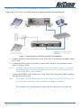
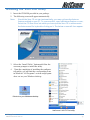
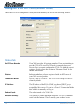
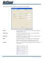
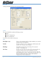
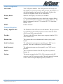
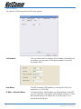
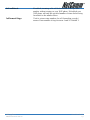
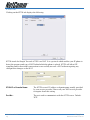
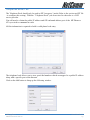
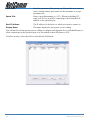
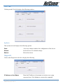
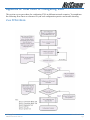
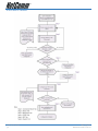
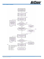
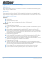
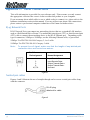
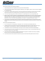
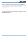
1
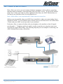
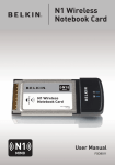
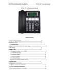
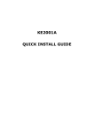
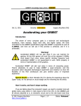
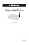
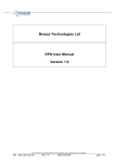
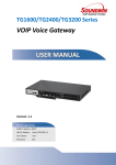
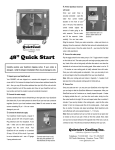
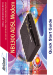
Contents
Introduction ................................................................................................................................ 4
Understanding VoIP .................................................................................................................... 5
Minimum System Requirements ................................................................................................. 6
Do I need a Micro filter? .............................................................................................................. 7
Package Contents ....................................................................................................................... 8
V100 ATA Overview ..................................................................................................................... 9
Front Indicators ..................................................................................................................... 9
Back Panel ........................................................................................................................... 10
V100 Start Up ....................................................................................................................... 11
Resetting the V100 ATA to its factory default settings: ........................................................ 11
Installing the V100 ATA .............................................................................................................. 12
Before continuing ... ............................................................................................................ 12
Option A - Ethernet ADSL Internet Connection ..................................................................... 13
Option B - Optus/Telstra Cable Internet Connection .......................................................... 14
Installing the V100 ATA Utility .................................................................................................... 15
Using the V100 ATA Configuration Utility ................................................................................... 16
Status Tab ........................................................................................................................... 16
Connection Mode Tab .......................................................................................................... 18
SIP Tab ............................................................................................................................... 20
Local ............................................................................................................................. 20
Host ........................................................................................................................ 20
Phone Configuration ................................................................................................ 21
Proxy and Registrar .................................................................................................. 21
Call Forward ................................................................................................................. 22
STUN Tab ...................................................................................................................... 24
Telephone Book Tab ........................................................................................................... 25
Tool Tab .............................................................................................................................. 27
System .......................................................................................................................... 27
Diagnostic ..................................................................................................................... 27
Upgrading the V100's Firmware .................................................................................... 28
V100 User Guide
2
YML749Rev1
www.netcomm.com.au
Appendix A: Flow Chart of Configuring V100 ............................................................................. 29
V100 PPPoE Mode ............................................................................................................... 29
V100 DHCP Mode ................................................................................................................ 30
V100 Fixed IP Mode ............................................................................................................. 31
Appendix B: Troubleshooting ................................................................................................... 32
WAN LED is off ........................................................................................................ 32
No dial tone ............................................................................................................ 32
Fail to register on a SIP server ................................................................................ 32
Cannot get bi-directional conversation ................................................................... 33
Cannot receive any incoming calls .......................................................................... 33
No DTMF tone at remote site .................................................................................. 33
Appendix C: Cable Connections ............................................................................................... 34
RJ-45 Network Ports ...................................................................................................... 34
Twisted pair cables ....................................................................................................... 34
Straight and crossover cable configuration ................................................................... 35
RJ11 connector and cable .............................................................................................. 35
605 to RJ-11 adapter ...................................................................................................... 35
Appendix D: Registering your NetComm Product .................................................................... 36
NetComm Contact Information ............................................................................................ 36
Appendix E: Legal & Regulatory Information ........................................................................... 37
Customer Information ......................................................................................................... 37
Product Warranty ............................................................................................................... 38
Limitations of Warranty ....................................................................................................... 39
IMPORTANT: UNDER NO CIRCUMSTANCES SHOULD THE ANALOGUE
PHONE PORT ON THE V100 ATA BE DIRECTLY
CONNECTED TO YOUR TELEPHONE LINE. IT SHOULD
ONLY BE USED TO CONNECT A TELEPHONE.
IMPORTANT: TO USE A VOIP PRODUCT YOU MUST ENSURE THAT
YOUR BROADBAND SERVICE PROVIDER AND
BROADBAND HARDWARE (MODEM/ROUTER) HAVE
BEEN DESIGNED TO HANDLE VOIP TRAFFIC. PLEASE
CHECK, IN BOTH CASES, BEFORE PROCEEDING WITH
THE INSTALLATION AND SET UP OF THIS PRODUCT.
YML749Rev1
www.netcomm.com.au
V100 User Guide
3
Introduction
Thank you for your purchase of NetComm's V100 VoIP ATA (Analogue Telephone Adapter).
The V100 ATA is a standards-based communication device that delivers true, next-generation voiceover-IP (VoIP) telephony to residences worldwide. The V100 ATA addresses the needs of smalloffice and home environments and emerging VoIP services by turning your analog phone into an IP
device. It supports a variety of protocols, including Real-time Transport Protocol (RTP) for transport
of multimedia data, Session Initiation Protocol (SIP) and Session Description Protocol (SDP) for call
signalling and control. It also supports STUN to allow your ATA to easily traverse firewalls/NAT
without requiring any configuration changes in your broadband router/modem. It can be easily
installed in many typical network topologies and allow other network devices to access the Internet
at the same time.
This guide covers installation of the V100 in various scenarios and with various broadband
connection types (ADSL or Cable).
V100 User Guide
4
YML749Rev1
www.netcomm.com.au
Understanding VoIP
You will be able to use your V100 ATA to make and receive calls depending on the type of VoIP plan
you subscribe to. In the below examples you have connected the V100 ATA to your standard
telephone handset and Broadband Internet Connection, i.e. Cable or DSL service.
1. VoIP Subscriber to VoIP subscriber on the same VoIP network.
In a basic VoIP plan you are issued with a virtual VoIP (telephone) number which allows you to
make and receive VoIP calls to other subscribers on the same VoIP service normally free of
charge.
2. VoIP Subscriber to VoIP subscriber on a different VoIP network.
With most VoIP plans you are not able to make VoIP to VoIP calls between different VoIP
networks unless your VoIP provider has setup a special provision for this to occur (i.e. VoIP
Gateway between networks).
However, some ATA’s such as the V100 can be configured manually to operate in a Peer-to-Peer
mode where the user sets up a series of quick dial numbers on their ATA to correspond to the IP
address of the VoIP user they wish to call on the alternate network. The other VoIP user must
also configure their ATA to operate in the same mode to accept your VoIP call. For further
configuration information please refer to ‘Telephone Book Tab’ section in this guide.
3. VoIP Subscriber to PSTN Telephone.
In this example you are able to make the same calls as described in 1 & 2.
You are also able to make calls to real world telephone subscribers - local, Interstate and
International. However, you are not able to receive calls from real world telephone subscribers as
you only have a Virtual VoIP (telephone) number.
4. PSTN Telephone to VoIP Subscriber.
In this example you have subscribed to a VoIP service plan that also provides you with a real
world telephone number instead of a virtual VoIP (telephone) number. Normally this type of
VoIP service plan has a monthly subscription fee.
With this plan you are able to make and receive calls to and from other VoIP subscribers on the
same VoIP service. You are not able to make VoIP to VoIP calls between different VoIP networks
unless your VoIP provider has setup a special provision for this to occur (i.e. VoIP Gateway
between networks).
You are also able to make and receive calls to and from real world telephone subscribers, local,
Interstate and International.
YML749Rev1
www.netcomm.com.au
V100 User Guide
5
Minimum System Requirements
■ A spare Ethernet port on the router or switch attached to your modem, if you wish to
access to the Internet..
■ A working broadband Internet connection. Consult an ISP if you do not have a broadband
connection.
■ A valid SIP VoIP account. There are generally two types available.
One type that only provides a VoIP number allows the V100 user to send and recieve calls
to and from other VoIP users. This service also allows the V100 user to call regular
telephone numbers, but not recieve calles from regular telephones.
The second type has an additional charge and provides the V100 user with a real world
telephone number that allows the V100 user to recieve calls from normal telephones. It
also provides all of the services of the first type.
Please contact a VoIP service provider and check the features in detail that their plans
offer.
■ You do not need a valid SIP VoIP account if you only want to make peer-to-peer calls.
(Refer to the section on Telephone Book Tab for instructions.)
■ Analogue telephone (e.g. Telstra phone or a DECT (cordless telephone) base station) to be
connected to the telephone (RJ11) port on the V100.
■ A microfilter is required if you have an ADSL connection and wish to connect another
telephone or facsimile directly to the line.
Note:
V100 User Guide
6
If you wish to use the caller ID feature, you will need a telephone with an LCD
screen. Additionally you will need a VoIP Service that supports these features.
Please check with your VoIP provider to acertain if they support features such as
Caller ID and Call Forwarding on their networks.
YML749Rev1
www.netcomm.com.au
Do I need a Micro filter?
Micro filters are used to prevent common telephone equipment, such as phones, answering
machines and fax machines, from interfering with your ADSL service. If your ADSL enabled
phone line is being used with any other equipment other than your ADSL Modem then you
will need to use one Micro filter for each phone device.
Note: A Microfilter is not required with a Cable Internet connection.
Splitters may be installed when your ADSL line is installed or when your current phone line is
upgraded to ADSL. If your telephone line is already split you will not need to use a Microfilter
- check with your ADSL service provider if you are unsure.
Each micro filter is connected in-line with your telephone or fax machine so that all signals
pass through it. Telephones and/or facsimiles in other rooms that are using the same extension will also require Microfilters. The following diagram gives an example of connecting your
ADSL Modem/Router using a Microfilter.
YML749Rev1
www.netcomm.com.au
V100 User Guide
7
Package Contents
The following items should be contained in your V100 Package:
■ V100 ATA
■ CD-ROM containing the Configuration Utility
and this Manual
■
RJ45 Ethernet Cable (CAT5 UTP Straight-Through)
■ RJ11 ADSL Cable (Standard telephone cable)
■ Power Adapter
■ This Installation Guide
Check the contents of your package and, if any parts are missing or damaged, please contact
your Dealer.
V100 User Guide
8
YML749Rev1
www.netcomm.com.au
V100 ATA Overview
Front Indicators
NUMBER
LABEL
DESCRIPTION
WAN
Lights up when WAN link and activity is
detected.
PHONE
Lights up when analog phone handset is
picked up; Or flashing at boot up period.
POWER
Lights up when device is powered on.
YML749Rev1
www.netcomm.com.au
V100 User Guide
9
Back Panel
NUMBER
LABEL
DESCRIPTION
Phone
Telephone jack (RJ-11) for connecting to an
analogue phone; also known as an FXS port.
Power
For connecting to the power adapter that
comes with the package.
Reset
To reset your V100 to its factory default
settings. (All customised settings that you
have saved will be lost!)
WAN
10/100 Base-T Ethernet Jack (RJ-45) for
connecting to your Broadband Modem,
Router or Switch.
NOTE:
V100 User Guide
10
Telstra and Optus Cable users must connect a DHCP enabled Router or Switch.
YML749Rev1
www.netcomm.com.au
V100 Start Up
1. Ensure that your V100 is powered on, as indicated by the Power LED.
2. WAN LED will light up if an ethernet cable is connected to the WAN port.
3. The Phone LED will begin flashing, indicating that the V100 is booting up.
4. When the phone LED stops flashing, the boot up process has finished.
Resetting the V100 ATA to its factory default settings:
1. Ensure that your V100 has completed booting up.
2. Use a paper clip or a pencil tip to depress the reset button for at lest 5 seconds and then
release the button.
3. At this point, the Phone LED light will flash a few times then stop. The reset process is
now in progress.
4. The Phone LED will continue flashing for a few seconds. Now the V100 has rebooted.
5. When the phone LED stops flashing, the reboot has finished.
YML749Rev1
www.netcomm.com.au
V100 User Guide
11
Installing the V100 ATA
This section covers the installation of the V100 ATA on your network.
Before continuing ...
Please ensure you have checked the following requirements:
■ A spare Ethernet port on the router or switch attached to your modem, if you wish to
access to the Internet..
■ A working broadband Internet connection; either Cable or ADSL. Consult an ISP if you do
not have a broadband connection.
■ A valid SIP VoIP account. There are generally two types available.
One type that only provides a VoIP number allows the V100 user to send and recieve calls
to and from other VoIP users. This service also allows the V100 user to call regular
telephone numbers, but not recieve calles from regular telephones.
The second type has an additional charge and provides the V100 user with a real world
telephone number that allows the V100 user to recieve calls from normal telephones. It
also provides all of the services of the first type.
Please contact a VoIP service provider and check the features in detail that their plans
offer.
■ You do not need a valid SIP VoIP account if you only want to make peer-to-peer calls.
(Refer to the section on Telephone Book Tab for instructions.)
■ Analogue telephone (e.g. Telstra phone or a DECT (cordless telephone) base station) to be
connected to the telephone (RJ11) port on the V100.
■ A microfilter is required if you have an ADSL connection and wish to connect another
telephone or facsimile directly to the line.
Note:
If you wish to use the caller ID feature, you will need a telephone with an LCD
screen. Additionally you will need a VoIP Service that supports these features.
Please check with your VoIP provider to acertain if they support features such as
Caller ID and Call Forwarding on their networks.
Once you have the above checklist completed, you can go to the section that relates to your
broadband Internet connection type to commence the setup of the V100 ATA on your network:
■ Option A - Ethernet ADSL Internet connection
■ Option B - Cable Internet connection
V100 User Guide
12
YML749Rev1
www.netcomm.com.au
Option A - Ethernet ADSL Internet Connection
Connect the V100 ATA to your ADSL modem as illustrated in the following diagram:
Figure 1 - Connecting the V100 ATA to an ADSL Router/Modem
1. Connect the Phone socket on the rear of your V100 ATA to an analogue telephone using a
RJ-11 cable.
2. Connect the WAN socket on your ATA to one of the LAN ports of your router/switch
using a Category 5 cable.
Note:
If you do not have any spare Ethernet ports on your ADSL modem / router and
you would like to connect to the Internet with your PC, you will need to add a
switch to the ADSL router/modem.
3. Connect the POWER socket on the rear of your V100 ATA to the power adaptor supplied
and plug into a wall socket.
Note:
If you have a Telstra telephone line you are still able to receive PSTN calls, but
you will need a microfilter and an additional analogue telephone.
Do not under any circumstanced connect the V100 directly to a phone line.
YML749Rev1
www.netcomm.com.au
V100 User Guide
13
Option B - Optus/Telstra Cable Internet Connection
Connect the V100 ATA to your Cable modem as illustrated in the following diagram:
Figure 2 - Connecting the V100 ATA to a Cable Modem
Note:
You also can connect the V100ATA directly to your cable modem. However, in
this connection other network devices, such as your PC, cannot share cable
modem Internet access.
1. Connect the Phone socket on the rear of your V100 ATA to an analogue telephone using a
RJ-11 cable.
2. Connect the WAN socket on the rear of your V100 ATA to the Ethernet port of your
router/switch using a Category 5 cable.
3. Connect the POWER socket on the rear of your V100 ATA to the power adaptor supplied
and plug into a wall socket.
V100 User Guide
14
YML749Rev1
www.netcomm.com.au
Installing the V100 ATA Utility
1. Insert the CD-ROM provided in your package.
2. The following screen will appear automatically.
Note:
Should the V100 CD not start automatically, you may not have the Autorun
feature enabled on your PC. To overcome this, open a Windows Explorer screen,
Select the CD-Rom drive into which you have put the V100 CD in and excecute
the Autorun.exe file by double clicking on it. The below screen will then appear.
3. Select the “Install Utility” button and follow the
onscreen prompts to install the utility.
4.
Upon the completion of installing the configuration utility, you will find the corresponding icons
in Windows "All Programs" section and program
short cut on your Windows desktop.
Shortcut on your Windows desktop
NetComm V100 PCTool utility
YML749Rev1
www.netcomm.com.au
V100 User Guide
15
Using the V100 ATA Configuration Utility
Once the V100 ATA Configuration Utility has been installed you will see the following window:
Status Tab
VoIP Phone Number:
Your VoIP provider will assign a number. If you are intending to
use the V100 ATA in an IP to IP mode (commonly known as
Peer-to-Peer) you must configure the V100 ATA with the correct
settings. Please refer to the section on Telephone Book Tab for
further instructions.
Status:
Indicates whether you have registered with the SIP server of
your VoIP service provider.
Connection Mode:
PPPoE / DHCP / Fixed IP - The V100 ATA is setup as a DHCP
client by default.
IP Address:
The IP address of the V100 ATA. If you have a DHCP server
running on your modem/router, the address indicated has been
assigned by this service. If you use a Fixed IP Connection Mode
this address is manually set by you.
Subnet Mask:
The subnet mask of the V100 ATA.
Default Gateway:
The gateway's address through which the V100 ATA communicates with the Internet. This is usually your modem / router.
V100 User Guide
16
YML749Rev1
www.netcomm.com.au
DNS 1:
The Domain Name Service that the V100 ATA uses to resolve
domain names to IP addresses. This is usually your modem /
router.
DNS 2:
The Domain Name Service that the V100 ATA uses to resolve
domain names to IP addresses. This is usually your modem /
router. DNS 2 can be a different address to DNS 1 to provide a
backup DNS server if DNS 1 fails.
MAC Address:
The unique hexadecimal hardware address of the V100 ATA's
NIC (Network Interface Card). This cannot be modified.
Status:
Indicates whether the ATA has correct communication with
DHCP server or PPPoE server when DHCP and PPPoE mode is
used respectively.
YML749Rev1
www.netcomm.com.au
V100 User Guide
17
Connection Mode Tab
Clicking on the Connection Mode tab brings up the following window:
PPPoE:
Select this option if your V100 ATA uses PPPoE to authenticate
with the modem / router.
User name:
The PPPoE account username. This is not your VoIP number.
This username is issued by your ISP.
Password:
The PPPoE account password. This is not your VoIP password.
This password is issued by your ISP.
DHCP:
Specifies that the V100 ATA must request its TCP/IP address
details from a DHCP service running on your network. This
service is usually available on your ADSL modem / router.
Fixed IP:
Allows you to specify the addressing details of the V100 ATA on
your network:
V100 User Guide
18
YML749Rev1
www.netcomm.com.au
IP Address:
The unique address of the V100 ATA on your network.
Subnet Mask:
The subnet mask of your network.
Default Gateway:
The gateway's address through which the V100 ATA communicates with the Internet. This is usually your modem / router.
DNS 1:
The Domain Name Service that the V100 ATA uses to resolve
domain names to IP addresses. This is usually your modem /
router.
DNS 2:
The Domain Name Service that the V100 ATA uses to resolve
domain names to IP addresses. This is usually your modem /
router. DNS 2 can be a different address to DNS 1 to provide a
backup DNS server if DNS 1 fails.
Once making any changes to the settings click the Apply button.
YML749Rev1
www.netcomm.com.au
V100 User Guide
19
SIP Tab
Clicking on the SIP tab brings up the following window:
Local
The sub-tab labelled Local has the following sections:
■ Host
■ Phone Configuration
■ Proxy and Registrar
Let us take a look at these sections now.
Host
Max Digits (1-24):
Indicates the maximum number of digits (numbers) you can dial
using the V100 ATA. Default: 24.
Port No.:
The port on the host used to communicate with the remote end.
Default: 5060. This port can be changed.
MaxRings:
The number of rings before an incoming call is answered.
Default: 15. Maximum is 50.
Use Proxy:
In order to use the V100 ATA with a VoIP service provider you
will need to specify a Proxy server which the V100 ATA
communicates with. Choose Yes and enter the details under the
Proxy and Registrar section. Choose No if you only want to use
the V100 in Peer-to-Peer mode. (Refer to the section on
Telephone Book Tab for instructions.)
V100 User Guide
20
YML749Rev1
www.netcomm.com.au
Phone Configuration
User Name:
Your VoIP phone number. Your VoIP provider will assign you
this number. If you are not with a VoIP provider, this number is a
self-defined number in Peer-to-Peer call mode. (Refer to the
section on Telephone Book Tab for instructions. )
Display Name:
What the called party sees when you call them.
Codec:
G.729 is a high compression codec which only occupies 8kbits/
sec, whereas G.711 alaw and G.711 ulaw require 64kbits/sec. We
highly recommend you use G.729 instead of G.711 alaw/ulaw.
Default: G.729.
DTMF:
Default: In-band.
Proxy and Registrar
Proxy / Registrar Info:
The IP address of the SIP server on the Internet. The proxy server
is responsible for forwarding requests received from the V100
ATA to your VoIP service provider.
Port No.:
The port on the SIP server that receives requests from the V100
ATA. Default: 5060.
Domain Info:
The registrar that saves information of where a party can be
found.
Auth User Name:
The authentication username assigned by your VoIP service
provider. This can be different to your VoIP number.
Auth Password:
The authentication password assigned by your VoIP service
provider.
Expire:
This is a duration of interval for SIP keep alive registration.
Default: 60.
Qvalue:
The priority assigned to the V100 ATA to register on the SIP
server of your VoIP service provider. The value must be between
0 and 1 with 1 having the highest priority. Default: 0.8.
YML749Rev1
www.netcomm.com.au
V100 User Guide
21
Call Forward
The sub-tab Call-Forward has the following options:
CallForward:
You can either enable or disable call forwarding. If enabling call
forwarding you can enter a VoIP phone number to forward
incoming calls to:
User Name:
The SIP username (VoIP number) to which calls will be forwarded to (e.g. 09100308).
IP Addr. or Domain Name:
Or Domain Name: The IP address or Domain Name of the SIP
server to which the User Name (VoIP number) belongs to (Note:
this domain name or IP address has to be the same as you
specified on the SIP tab).
V100 User Guide
22
YML749Rev1
www.netcomm.com.au
UnConditional:
If enabled, incoming calls will be forwarded to the specified
number without ringing on your VoIP phone. If disabled your
VoIP phone will ring the specified number of times before being
forwarded to the number above.
CallForward Rings:
Used to set max ring numbers for call forwarding on reply/
answer. Enter number of rings between 1 and 20. Default: 5.
YML749Rev1
www.netcomm.com.au
V100 User Guide
23
STUN Tab
Clicking on the STUN tab displays the following:
STUN stands for Simple Traveral of UDP over NAT. It is a protocol which enables your IP phone to
detect the presence and type of NAT behind which the phone is placed. STUN will allow SIP
signalling and bi-directional conversation to successfully traverse a NAT without requiring any
configuration changes on the NAT.
STUN IP or Domain Name:
The STUN server's IP address or domain name usually provided
by your service provider. Please call your VoIP service provider
to enquire about this setting.
Port No.:
The port used to communicate with the STUN server. Default:
3478.
V100 User Guide
24
YML749Rev1
www.netcomm.com.au
Telephone Book Tab
The Telephone Book should only be used in SIP "non-proxy" mode (Refer to the section on SIP Tab
- to configure this setting). With the "Telephone Book" you do not need to subscribe to a VoIP
service provider.
You will need to obtain the public IP address and SIP outbound address port of the SIP Phone or
ATA you wish to communicate with.
All this information is required to build a valid phone book entry.
The telephone book allows you to store speed dial numbers which are mapped to a public IP address
along with a specific port on the Internet.
Click on the Add button to bring up the following window:
YML749Rev1
www.netcomm.com.au
V100 User Guide
25
User Name:
Enter the username of the person (e.g. Kirstin) that you want to
reach. And the remote party must use this username to accept
incoming calls.
Speed Dial:
Enter a speed dial number (e.g. 123). Whenever dialling 123
using your V100 you will be connecting to the Destination IP
address on the specified port.
Dest IP Address:
The IP address of the device to which you want to connect to.
Display Name:
The name displayed to the person you are calling.
You will need to ask the person you are calling to configure their Internet device (Modem/Router) to
allow connections on the specified port to be forwarded to their SIP phone or ATA.
To delete an entry, select the tick box and click the Del button:
V100 User Guide
26
YML749Rev1
www.netcomm.com.au
Tool Tab
Clicking on the Tool tab displays the following window:
System
The System sub-tab displays the following options:
Save:
Saves any changes made to the configuration of the device.
Default:
Set the device to its default settings.
Reboot:
Reboot the device.
Diagnostic
Click on the Diagnostic sub-tab to display the following:
IP Address or Host Name:
YML749Rev1
www.netcomm.com.au
Enter the IP address or host name you wish to test a ping
response from. Click Submit to execute the command.
V100 User Guide
27
Upgrading the V100's Firmware
To upgrade the V100's firmware please download the latest version from the NetComm website. See
www.netcomm.com.au.
1. Create a folder on you PC and copy the downloaded file to this folder.
2. Next run your V100 ATA Utility. Select the Upgrade tab.
3. Next type in the location of the firmware upgrade file and its name in 'The Image File' field.
Alternativly, you can click on the button with the 3 dots located next to this field and
browse your PC for the file’s location.
4. Click the “Upgrade” button once you have located the file.
5. A popup screen will be displayed with a message indicating that the firmware is being
upgraded.
6. The V100 will automatically reboot itself once the firmware upgrade has finished.
Warning: Do not unplug the power from the V100 while the firmware upgrade is in
progress. Unplugging the device will cause serious damage to your V100.
V100 User Guide
28
YML749Rev1
www.netcomm.com.au
Appendix A: Flow Chart of Configuring V100
This section covers procedures for configuring V100 in different network scenarios. You might use
the following flow charts as reference for your real configuration practice and trouble shooting.
V100 PPPoE Mode
YML749Rev1
www.netcomm.com.au
V100 User Guide
29
V100 DHCP Mode
V100 User Guide
30
YML749Rev1
www.netcomm.com.au
V100 Fixed IP Mode
YML749Rev1
www.netcomm.com.au
V100 User Guide
31
Appendix B: Troubleshooting
WAN LED is off
Please check whether your V100 is connected to a switch or a broadband router/modem properly
using a category 5 Ethernet cable.
No dial tone
If you cannot hear a dial tone after the V100 has completely booted up, please see Appendix A and
follow the steps to diagnose problems based on the connection type you are using (Cable or DSL).
Fail to register on a SIP server
Symptoms:
■ No dial tone;
■ Unable to make/receive calls;
■ The “Status” page of configuration utility shows “Not Registered”.
Checkpoints:
1) Diagnosing Internet connection
■ If you are using xDSL broadband, check whether your xDSL router/modem has got line
sync.
■ Check whether your router/modem has established PPP connection with your ISP.
■ If your V100 uses PPPoE mode, your xDSL router/modem has to work in bridge mode.
Check whether your V100 can establish PPP connection (refer to the section on Connection Mode Tab for more information).
2) Diagnosing V100 connection
■ If you choose DHCP, please make sure your V100 has been assigned a valid IP address
from your DHCP server (refer to the section on Status Tab for more information)
■ If you choose FixedIP, please check whether you inputted an unused IP address, correct
subnet mask, default gateway and DNS server IP address.
3) Diagnosing your SIP account
■ You have to make sure all SIP account information is correct including SIP username,
Auth. ID, Auth. Password, SIP server domain name/IP address and SIP server registration
port (refer to the section on SIP Tab for details for more information).
■ Do not change SIP server registration port unless you know what you are doing.
■ If you are unsure about these parameters please call your VoIP service provider.
V100 User Guide
32
YML749Rev1
www.netcomm.com.au
Cannot get bi-directional conversation
Symptoms:
Register to a VoIP provider’s SIP server is successful.
You can make and receive calls. However, you cannot hear remote party’s voice or in some
situations both sides cannot hear each other.
Checkpoints:
■ If your V100 is behind a NAT/Firewall, call your VoIP provider to see whether you need
STUN support to traverse a NAT/Firewall.
■ Configure your STUN client using correct STUN server information (refer to the section on
STUN Tab for more information). Your VoIP provider might provide you this information.
Cannot receive any incoming calls
If you cannot receive any incoming calls, please make sure “UnConditional” call forwarding is
disabled. This function blocks all incoming calls and forwards them to the phone number you
specified in configuration.
No DTMF tone at remote site
If the remote site cannot properly get DTMF tones that are generated from your side, please try
different DTMF relay mode (in band or RFC 2833).
YML749Rev1
www.netcomm.com.au
V100 User Guide
33
Appendix C: Cable Connections
This cable information is provided for your reference only. Please ensure you only connect
the appropriate cable into the correct socket on either this product or your computer.
If you are unsure about which cable to use or which socket to connect it to, please refer to the
hardware installation section in this manual. If you are still not sure about cable connections,
please contact a professional computer technician or NetComm for further advice.
RJ-45 Network Ports
RJ-45 Network Ports can connect any networking devices that use a standard LAN interface,
such as a Hub/Switch Hub or Router. Use unshielded twisted-pair (UTP) or shield twisted-pair
(STP) cable to connect the networking device to the RJ-45 Ethernet port. Depending on the
type of connection, 10Mbps or 100Mbps, use the following Ethernet cable, as prescribed.
10Mbps: Use EIA/TIA-568-100-Category 3, 4 or 5 cable.
100Mbps: Use EIA/TIA-568-100-Category 5 cable.
Note:
To prevent loss of signal, make sure that the length of any twisted-pair
connection does not exceed 100 metres.
RJ-45 Connector
Pin Assignment
1
2
3
6
4,5,7,8
Normal Assignment
Input Receive Data +
Input Receive Data Output Transmit Data +
Output Transmit Data Not used
Figure 1
Twisted pair cables
Figures 1 and 2 illustrate the use of straight-through and crossover twisted pair cables along
with the connector.
RJ-45 plug
attached to cable
Figure 2
V100 User Guide
34
YML749Rev1
www.netcomm.com.au
Straight and crossover cable configuration
Figure 3
Figure 4
RJ11 connector and cable
An RJ-11 connector is the small, modular plug used for most analog telephones. It has six pin
slots in the head, but usually only two or four of them are used.
RJ-11 Connector
Pin Assignment
1
2
3
4
5
6
Normal Assignment
Not Connected
Not connected
Line
Line
Not Connected
Not Connected
Figure 5
605 to RJ-11 adapter
The 605 to RJ-11 adaptor is provided to comply with the older 610 Telstra wall socket. The 605
to RJ-11 adapter may be used to convert the supplied RJ-11 cable, if the older connection is
required.
YML749Rev1
www.netcomm.com.au
V100 User Guide
35
Appendix D: Registering your NetComm Product
All NetComm Limited (“NetComm”) products have a standard 12 month warranty from date
of purchase against defects in manufacturing and that the products will operate in accordance
with the specifications outlined in the User Guide. However some products have an extended
warranty option (please refer to packaging). To be eligible for the extended warranty you must
supply the requested warranty information to NetComm within 30 days of the original
purchase by registering on-line via the NetComm web site at:
www.netcomm.com.au
NetComm Contact Information
If you have any technical difficulties with your product, please do not hesitate to contact
NetComm’s Customer Support Department.
Email:
[email protected]
Fax:
(+612) 9424-2010
Web:
www.netcomm.com.au
V100 User Guide
36
YML749Rev1
www.netcomm.com.au
Appendix E: Legal & Regulatory Information
This manual is copyright. Apart from any fair dealing for the purposes of private study, research, criticism or review, as
permitted under the Copyright Act, no part may be reproduced, stored in a retrieval system or transmitted in any form, by
any means, be it electronic, mechanical, recording or otherwise, without the prior written permission of NetComm
Limited. NetComm Limited accepts no liability or responsibility, for consequences arising from the use of this product.
NetComm Limited reserves the right to change the specifications and operating details of this product without notice.
NetComm is a registered trademark of NetComm Limited.
All other trademarks are acknowledged the property of their respective owners.
Customer Information
ACA (Australian Communications Authority) requires you to be aware of the following information and warnings:
(1) This unit shall be connected to the Telecommunication Network through a line cord which meets the requirements of
the ACA TS008 Standard.
(2) This equipment has been tested and found to comply with the Standards for C-Tick and or A-Tick as set by the ACA
. These standards are designed to provide reasonable protection against harmful interference in a residential
installation. This equipment generates, uses, and can radiate radio noise and, if not installed and used in
accordance with the instructions detailed within this manual, may cause interference to radio communications.
However, there is no guarantee that interference will not occur with the installation of this product in your home or
office. If this equipment does cause some degree of interference to radio or television reception, which can be
determined by turning the equipment off and on, we encourage the user to try to correct the interference by one or
more of the following measures:
•
Change the direction or relocate the receiving antenna.
•
Increase the separation between this equipment and the receiver.
•
Connect the equipment to an alternate power outlet on a different power circuit from that to which the receiver/TV is
connected.
•
Consult an experienced radio/TV technician for help.
(3) The power supply that is provided with this unit is only intended for use with this product. Do not use this power
supply with any other product or do not use any other power supply that is not approved for use with this product by
NetComm. Failure to do so may cause damage to this product, fire or result in personal injury.
YML749Rev1
www.netcomm.com.au
V100 User Guide
37
Product Warranty
The warranty is granted on the following conditions:
1.
This warranty extends to the original purchaser (you) and is not transferable;
2.
This warranty shall not apply to software programs, batteries, power supplies, cables or other accessories supplied
in or with the product;
3.
The customer complies with all of the terms of any relevant agreement with NetComm and any other reasonable
requirements of NetComm including producing such evidence of purchase as NetComm may require;
4.
The cost of transporting product to and from NetComm's nominated premises is your responsibility; and,
5.
NetComm does not have any liability or responsibility under this warranty where any cost, loss, injury or damage of
any kind, whether direct, indirect, consequential, incidental or otherwise arises out of events beyond NetComm's
reasonable control. This includes but is not limited to: acts of God, war, riot, embargoes, acts of civil or military
authorities, fire, floods, electricity outages, lightning, power surges, or shortages of materials or labour.
6.
The customer is responsible for the security of their computer and network at all times. Security features may be
disabled within the factory default settings. NetComm recommends that you enable these features to enhance your
security.
The warranty is automatically voided if:
1.
You, or someone else, use the product, or attempts to use it, other than as specified by NetComm;
2.
The fault or defect in your product is the result of a voltage surge subjected to the product either by the way of
power supply or communication line, whether caused by thunderstorm activity or any other cause(s);
3.
The fault is the result of accidental damage or damage in transit, including but not limited to liquid spillage;
4.
Your product has been used for any purposes other than that for which it is sold, or in any way other than in strict
accordance with the user manual supplied;
5.
Your product has been repaired or modified or attempted to be repaired or modified, other than by a qualified
person at a service centre authorised by NetComm; and,
6.
The serial number has been defaced or altered in any way or if the serial number plate has been removed.
V100 User Guide
38
YML749Rev1
www.netcomm.com.au
Limitations of Warranty
The Trade Practices Act 1974 and corresponding State and Territory Fair Trading Acts or legalisation of another
Government ("the relevant acts") in certain circumstances imply mandatory conditions and warranties which cannot be
excluded. This warranty is in addition to and not in replacement for such conditions and warranties.
To the extent permitted by the Relevant Acts, in relation to your product and any other materials provided with the product
("the Goods") the liability of NetComm under the Relevant Acts is limited at the option of NetComm to:
■
Replacement of the Goods; or
■
Repair of the Goods; or
■
Payment of the cost of replacing the Goods; or
■
Payment of the cost of having the Goods repaired.
All NetComm ACN 002 490 486 products have a standard 12 months warranty from date of purchase. However some
products have an extended warranty option (refer to packaging). To be eligible for the extended warranty you must supply
the requested warranty information to NetComm within 30 days of the original purchase by registering on-line via the
NetComm web site at www.netcomm.com.au.
YML749Rev1
www.netcomm.com.au
V100 User Guide
39