1
N8405-024F
Blade Enclosure (SIGMABLADE-H)
User's Guide
855-900677-A
PN# 456-01750-000
2008 Apr. 2nd Edition
Note
Read this guide carefully before using this product.
Always keep this guide at hand so that you can see it when necessary.
1
FCC COMPLIANCE
This product has been tested and found to comply with the limits for a Class A digital device,
pursuant to Part 15 of the FCC rules. These limits are designed to provide reasonable protection
against harmful interface when the device is operated in a commercial environment. This
device generates, uses and can radiate radio frequency energy and if not installed and used in
accordance with the instruction manual, may cause harmful interference to radio
communications. Operation of this device in a residential area is likely to cause harmful
interface in which case the user will be required to correct the interference at his own expense.
Warning
To meet FCC rule, use the following rack with front and rear doors in place and closed.
Never operate without doors and under doors are opened.
APC “NetShelter® VX 42U Enclosure w/Sides Black” [AR2100BLK]
CE and C-Tick STATEMENTS
Warning
This is Class A product. In a domestic environment this product may cause radio interference in
which case the user may be required to take adequate measures.
Trademarks
NEC EXPRESSBUILDER and NEC ESMPRO, NEC DianaScope, EXPRESSSCOPE, NEC ExpressCluster,
SigmaSystemCenter, WebSAM, DeploymentManager and VALMOware Network Manager are trademarks or registered
trademarks of NEC Corporation.
Microsoft, Windows, Windows Server, Internet Explorer, .NET Framework are trademarks or registered trademarks of Microsoft
Corporation in the United States and other countries.
Intel and Pentium are registered trademarks of Intel Corporation.
HP-UX is a registered trade mark of Hewlett-Packard Company.
Wake on LAN is a trade mark or registered trademark of International Business Machines Corporation.
Java and all logos related to Java are trademarks or registered trademarks of Sun Microsystems, Inc.
Tomcat is a trademark or registered trademark of Apache Software Foundation.
Linux is a trademark or registered trademark of LinusTorvalds in the United States and other countries.
All other product, brand or trade names mentioned in this publication are the trademarks or registered trademarks of their
respective companies.
Microsoft® Windows ServerTM 2003, Standard Edition, Microsoft® Windows ServerTM 2003, Enterprise Edition, Microsoft®
Windows ServerTM 2003, Datacenter Edition, Windows ServerTM 2003, Standard x64 Edition, Windows ServerTM 2003, and
Enterprise x64 Edition are called Windows Server 2003 in short.
Microsoft® Windows ServerTM 2003 R2, Standard Edition, Microsoft® Windows ServerTM 2003 R2, Enterprise Edition,
Microsoft® Windows ServerTM 2003 R2, Datacenter Edition, Microsoft® Windows ServerTM 2003 R2, Standard x64 Edition,
Microsoft® Windows ServerTM 2003 R2, Enterprise x64 Edition, Microsoft® Windows ServerTM 2003 R2, and Datacenter x64
Edition are called Windows Server 2003 R2 in short.
Microsoft® Windows® 2000 Server operating system, Microsoft® Windows® 2000 Advanced Server operating system,
Microsoft® Windows® 2000 Professional operating system are called Windows 2000 in shot.
Microsoft® Internet Explorer is called Internet Explorer for short.
Java Runtime Environment is called JRE for short.
Names used with sample applications are all fictitious. They are unrelated to any existing product names, names of organizations,
or individual names.
Notes
(1)
(2)
(3)
(4)
No part of this manual may be reproduced in any form without prior written permission of NEC Corporation
The contents of this manual are subject to change without prior notice.
The contents of this manual shall not be copied or altered without prior written permission of NEC Corporation
All efforts have been made to ensure the accuracy of all information in this manual. If you find any part unclear,
incorrect, or omitted in this manual, contact the sales representative where you purchased this product.
(5) NEC assumes no liability arising from the use of this product, nor any liability for incidental or consequential
damage arising from the use of this manual regardless of (4) above.
2
Note
Keep this User's Guide handy for quick reference when necessary.
Make sure to read "Notes for safe handling." When you relocate the product, make sure to take this
guide with the product.
Notes for safe handling
This section provides information for using the product safely.
SAFETY INIDICATIONS
To use this product safely, follow the instructions in this User's Guide.
This guide explains components that pose a danger, types of dangers caused by failing to follow the
instructions, and actions taken to prevent them; such components are labeled warning.
This guide and warning labels use "WARNING" and "CAUTION" to indicate a danger depending
on the degree. These terms are defined as follows:
WARNING
Indicates there is a risk of death or serious injury.
CAUTION
Indicates there is a risk of burn or injury.
This guide uses the following three types of symbols to give indications and precautions against a
danger. They are defined as follows:
Attention
Prohibited
actions
Mandatory
actions
This symbol indicates the presence of a hazard.
An image in the symbol illustrates the hazard
type.
This symbol indicates prohibited actions. An
image in the symbol illustrates a particular
prohibited action.
This symbol indicates mandatory actions. An
image in the symbol illustrates a mandatory action
to avoid a particular hazard.
(Example)
(Electric
shock)
(Example)
(Do not
disassemble)
(Example)
(Unplug)
Example of indications in this guide
Symbol indicating attention Description of a danger Term indicating degree of danger
CAUTION
Do not plug the cord into a nonconforming outlet.
Use wall outlets with specified voltage and power type. Failure to observe this
caution could result in a fire or current leakage.
3
Symbols and their descriptions used in this User's Guide
and warning labels are as follows:
Attention
Indicates the risk of electric
shock.
Indicates the risk of explosion.
Indicates the risk of injury due to
a caught hand or finger.
Indicates the risk of smoke emission
or fire outbreak.
Indicates the risk of burn due to
hot surface.
Indicates the risk of injury due to
rotation of objects.
Indicates a general notice or
warning that cannot be
specifically identified.
Prohibited actions
Indicates prohibition of
disassembling or reconfiguring
the unit.
Avoid using water or liquid nearby.
If it spills on the card, there is a risk
of electric shock or fire.
Do not touch with wet hands.
There is a risk of electric shock.
Indicates notice of general
prohibition.
Mandatory actions
Indicates instructions to pull
power plug from outlet and to
turn off main circuit breaker.
Indicates required general actions for
operators.
4
Precautions for safety
Observe the precautions for safety described in this section. The blade enclosure
(SIGMABLADE-H) on which this card is installed has power units. Carefully use them to avoid
any electric shock.
.
General precautions
WARNING
Do not use this product for services where critical high availability may
directly affect human lives.
This product is not intended to be used with or control facilities or devices
concerning human lives, including medical devices, nuclear facilities and
devices, aeronautics and space devices, transportation facilities and devices; and
facilities and devices requiring high reliability. NEC assumes no liability for any
accident resulting in personal injury, death, or property damage if this product
has been used in the above conditions.
Do not disassemble, repair, or alter this product.
Never disassemble, repair, or alter this product on any occasion other than
described in this manual, otherwise it may cause an electric shock or fire as well
as malfunctions of this product.
Do not use this product if any smoke, odor, or noise is present.
If smoke, odor, or noise is present, immediately turn off the POWER of the CPU
blades and disconnect the power plug from the outlet, then contact your sales
representative. Using this product in such conditions may cause a fire.
Do not insert a wire or metal object.
Do not insert a wire or metal objects into a vent or a slot. There is a risk of
electric shock.
Do not install or remove multiple CPU blades at the same time.
Install or remove CPU blades one at a time. If you install or remove two or more
CPU blades, or install a CPU blade while the cover of another slot is removed, there
is a risk of electric shock.
5
CAUTION
Prevent water or foreign objects from the product.
Do not allow water or foreign objects (e.g., pins or paper clips) to enter into the
product. There is a risk of fire, electric shock, and breakdown. When such things
accidentally enter the server, immediately turn off the power and unplug the cords.
Contact your sales representative instead of trying to disassemble it yourself.
Connect firmly.
Connect interface cables, option boards, and modules to the CPU blade securely.
Install the card securely on the blade enclosure. Failure to connect or install securely
may result in poor contact that can cause a fire or smoke.
Do not use any unauthorized interface cable.
Use only the interface cable that comes with this product. Use of an unauthorized
interface cable may cause a fire when the electric current exceeds the rated flow.
Also, observe the following to prevent an electric shock or fire caused by a
damaged cord.
Do not touch the fan blades when moving.
Keep your hands or hair away from the cooling fans on the rear of the blade
enclosure; otherwise they may get caught in the fan, resulting in injury. Do not
insert an object in the fan. Doing so may cause personal injury as well as the
malfunction of the device.
Do not touch the heated objects.
Immediately after the blade enclosure is powered off, components in the blade
enclosure and CPU blades are very hot. Leave the blade enclosure until those
components fully cool down before installing/removing any component. In
addition, hot air is exhausted from the power supply fan. Keep your face and
hands away from the air outlet.
Avoid contact with the blade enclosure during thunderstorms.
Disconnect the power plug from the outlet when a thunderstorm is approaching.
If it starts thundering before you disconnect the power plug, do not touch any
part of the blade enclosure including the cables, otherwise it may cause a fire or
an electric shock.
Keep animals away.
Keep animals away from the product. Animal waste or hair may get inside the
product, causing a fire or electric shock.
Do not use a cellular phone or pager near the product.
Turn off your cellular phone or pager when you use the product. Their radio waves
may cause the server to malfunction.
6
Power Supply and Power Cord
WARNING
Do not hold the power plug with wet hands.
Do not disconnect/connect the plug while your hands are wet, otherwise it may cause
an electric shock.
Do not connect the protective earthing conductor to a gas pipe.
Never connect the protective earthing conductor to a gas pipe; otherwise it may
cause a gas explosion.
CAUTION
Plug into a proper power source.
Use a proper wall outlet. Use of an improper power source may cause a fire or a
leak. Do not install the blade enclosure where you need an extension cord.
Use of a cord that does not meet the power specifications of the blade enclosure may
heat up the cord and cause a fire. The maximum power consumption per power unit
is 3000 VA. Note the capacity of a power unit when it is connected to CPU blades.
Do not connect many loads on one electrical outlet.
The electric current exceeding the rated flow overheats the outlet, which may cause a
fire.
Place the power supply tap in a place where it is noticeable and easy to
access.
Place the power supply tap in a place where it is noticeable and easy to access so that
power can be shut off in emergency.
Insert the power plug completely.
Heat generation resulting from a halfway inserted power plug (imperfect contact)
may cause a fire. Heat will also be generated if condensation is formed on dusty
blades of the halfway inserted plug, increasing the possibility of fire.
Use the proper power cord only
Use of an improper power cord may cause a fire when the electric current exceeds
the rated flow. Also, observe the following to prevent an electric shock or fire caused
by a damaged cord.
Do not stretch the cord harness.
Do not pinch the power cord.
Do not bend the power cord.
Keep chemicals away from the power cord.
Do not twist the power cord.
Do not place any object on the power cord.
Do not bundle power cords.
Do not alter, modify, or repair the power cord.
Do not secure the power cord with staples or equivalents.
Do not use any damaged power cord. (Replace a damaged power cord with a new
one of the same specifications. Ask your sales representative for detailed information
on power code.)
7
Installation and handling of the rack
WARNING
Install the server rack ONLY in a specified or designated environment
Do not install the rack on which the blade enclosure is installed in an unsuitable
place.
Other devices installed on the blade enclosure or the rack may be affected, a fire may
occur, or the rack may fall, causing injury. For details about installation environment
and quake-resistant engineering, see the manual attached to the rack or contact your
maintenance service agent.
Do not install the blade enclosure in a non-conforming rack
Install the blade enclosure in a 19-inch rack conforming to the EIA standard. Do not
install the blade enclosure in a nonconforming rack, otherwise devices on the blade
enclosure may not function properly, and there is a risk of injuries or damage to
physical assets. For more information about suitable racks on which the blade
enclosure can be installed, contact your sales representative.
Set up noise treatment
The blade enclosure may emit loud noises from fans when it is operating. It is
recommended to install the blade enclosure in a dedicated room that is distant from
people. Arrange acoustic noise treatment such as partitions if you work near the
operating blade enclosure for a long period of time.
8
CAUTION
Do not carry or install alone.
Carry or install a rack with two or more people. If the rack is carried by one person,
the rack may fall and cause injury or damage to physical assets. A tall rack such as a
44 U rack, in particular, is unstable if it is not fixed by stabilizers. Make sure to
support the rack with two or more people to carry and/or fix it.
Do not install the rack in such a manner that weight is imposed on a single
spot.
Avoid concentration of weight loads of the rack and units installed on a single spot.
Use stabilizers or connect two or more racks to balance loads. If not, the rack may
fall over and cause injury.
Do not carry or remove parts alone.
Do not work alone to install or remove a part such as a rack door and tray. The part
may fall and be damaged, and there is a risk of injury.
Use a lifter to install a unit.
Use a lifter to install/remove a unit. Otherwise, the unit may fall and be damaged,
and there is a risk of injury especially when you are working with a tall rack (such as
44U rack).
Do not pull out a unit when the rack is not stabilized.
When you pull out a unit from the device, make sure that the rack is fixed (by using
stabilizers or quake-resistant engineering).
Do not pull out two or more units from the rack at the same time.
When two or more units are pulled out from the rack, the rack may fall over. Pull out
one unit at a time.
Do not install excessive wiring beyond the rated power supply.
To prevent burns, fires, and damage to the rack, make sure that the rated load of the
power branch circuit is not exceeded. For more information on installation and
wiring of power-related facilities, contact your electrician or local power company.
9
Installation, relocation and storage of the blade enclosure
WARNING
Separate the blade enclosure into two components and carry each
component with two or more people.
When you want to carry the blade enclosure, separate the rear cage from the module
to make the blade enclosure into two components. With no modules such as a CPU
blade or power unit installed, the enclosure and the rear cage weigh 35.5kg and
31.5kg respectively. Carrying the enclosure or rear cage alone may result in injury.
Carry the enclosure/rear cage with two or more people and firmly hold the handles
of the enclosure or any designated areas. Do not carry the blade enclosure if any
module, such as a CPU blade or power unit, is installed.
Do not install the blade enclosure in a place other than specified.
Do not install the blade enclosure in a place other than specified in this guide. Avoid
the following locations. There is a risk of fire.
● a dusty place
● a humid place located near a boiler, etc.
● a place exposed to direct sunlight
● an unstable place
● a non-restricted access place
Do not use or store the blade enclosure in a corrosive environment.
Avoid using or storing the blade enclosure in an environment which may be exposed
to corrosive gases, such as those including but not limited to: sulfur dioxide,
hydrogen sulfide, nitrogen dioxide, chlorine, ammonia and/or ozone. Avoid
installing the blade enclosure in a dusty environment or a place that may be exposed
to corrosive materials such as sodium chloride and/or sulfur.
Avoid installing the blade enclosure in an environment that may have excessive
metal flakes or conductive particles in the air.
Such environments may cause corrosion or short circuits within the blade enclosure,
resulting in damage to the blade enclosure and possibly a fire hazard.
If there are any concerns regarding the environment at the planned site of installation
or storage, please contact your sales representative.
Do not use the blade enclosure with its covers and fan units removed.
Do not use the blade enclosure with its covers and fans removed. If you use the
blade enclosure without them, the cooling efficiency inside the blade enclosure
degrades, causing malfunction. Also, dust may get in and cause a fire or electric
shock.
Be careful not to hurt your fingers.
Take precautions to avoid pinching your fingers when installing or removing the
blade server on or from the rack.
Be careful not to drop the blade enclosure.
Firmly hold the handles on both sides of the blade enclosure to install or remove it
on the rack. Since brackets on the rack have no mechanism to prevent the device
from falling off, such as a stopper or lock, pulling a device fully out of the rack can
result in the device falling and causing injury. When you install or remove the blade
enclosure, hold the handles on both sides firmly or use a lifter.
10
WARNING
Do not impose loads on the blade enclosure while it is pulled out of the rack.
Do not impose loads on the top of the blade enclosure while it is pulled out from the
rack. The frame may be damaged, and you may not be able to install the blade
enclosure on the rack. There is a risk of the blade enclosure falling and causing
injury as well.
Do not cover ventilation openings.
Do not cover ventilation openings of the blade enclosure. Additionally, do not cover
rack openings. If they are covered, the temperature of devices on the blade enclosure
may rise, which may result in a fire.
CAUTION
Do not leave the blade enclosure pulled out of the rack.
Do not operate or perform maintenance with the blade enclosure pulled out. Since
the brackets on the rack have no mechanism to prevent the blade enclosure from
falling off, such as a stopper or lock, pulling the blade enclosure fully out of the rack
can result in the blade enclosure falling and causing injury.
Do not hold any installed module or power unit cover.
When you carry the blade enclosure, do not hold any installed module or power
unit cover. Because they are movable, you might drop the blade enclosure if you
hold them.
Wear a wrist strap to eliminate static electricity.
Installed modules and peripheral devices contain parts that are sensitive to
electrostatic discharge. Wear a wrist strap to eliminate static electricity when you
install or remove the modules or peripheral devices or connect interface cables.
11
Failure action
WARNING
Failure action.
When the device fails, shut off the branch circuit breaker of the power distribution
board, unplug the device, and contact your sales maintenance personnel.
Disposal
CAUTION
Lithium battery.
The EM card installed on the blade enclosure uses a lithium battery (the battery is
not replaceable). Contact your NEC sales representative before disposing the EM
card.
Disposal and recycling.
Contact your NEC sales representative before disposal, collection, or recycling of
the device.
12
Maintenance, cleaning and handling of internal devices
WARNING
Do not place your hands inside the blade enclosure.
Do not place your hands inside the blade enclosure when you install or remove it.
There is a risk of electric shock. Do not remove the cover attached to the blade
enclosure except when necessary, such as when installing a device.
Installation/removal of a device should be done one by one.
CAUTION
Unplug power cords before maintenance.
Before maintenance, power off all devices installed on the blade enclosure and
unplug the power cords. Even if devices are powered off, there is a risk of electric
shock or fire as well as malfunction when maintenance is performed on the devices
on the blade enclosure with their power cords plugged in.
Disconnect the power plugs from the outlet occasionally and clean the plugs with a
dry cloth. Heat will be generated if condensation is formed on a dusty plug, which
may cause a fire.
During operation
CAUTION
Do not touch when it thunders.
Unplug the power plugs when a thunderstorm is approaching. If it starts to thunder
before you unplug them, do not touch the blade enclosure and cables. There is a risk
of fire or electric shock.
Keep animals away.
Keep animals away from the blade enclosure. Animal waste or hair may get inside
the blade enclosure and cause a fire or electric shock.
Do not pull out the blade enclosure from the rack while it is running.
Do not pull out or remove the blade enclosure from the rack while a device on the
blade enclosure is running. The device may malfunction, and there is a risk of injury.
Do not place any unfixed equipment on the top of the blade enclosure.
To avoid the risk of personal injury or damage to the equipment, never place unfixed
equipment on top of the blade enclosure.
13
Disposing of your used NEC product
In the European Union
EU-wide legislation as implemented in each Member State requires that used
electrical and electronic products carrying the mark (left) must be disposed of
separately from normal household waste. When disposing of used NEC
products, you should comply with applicable legislation or such terms which
may have been agreed between NEC and your company regarding used
products. The mark on the electrical and electronic products only applies to the
current European Union Member States.
Outside the European Union
If you wish to dispose of used electrical and electronic products outside the
European Union, please contact your local authority and ask for the correct
method of disposal.
Warning labels
Warning labels are placed in certain parts of the blade enclosure so that the user stays alert to
possible risks that may arise.
(Do not remove or damage these labels).
If a label is missing, peeling off, or illegible, contact your sales representative.
For information on symbols in the labels, see "Safety indications" at the top of this document.
14
Handling precautions to use the device correctly
Observe the following precautions to use the blade enclosure device correctly. Failure to observe
the precautions can result in malfunction or mechanical error.
About maintenance services
Hint
Diagnostic and maintenance services by personnel with expertise on maintenance of
the blade enclosure are available.
● Blade enclosure
- Use a rack that allows installation of the blade enclosure.
- This product must be installed in a restricted access location.
- Make sure to install or remove parts, such as fan units, correctly when a module is installed
or removed.
- Remove the dust on the exterior and fans located at the front and rear of the blade enclosure
regularly. Regular cleaning prevents various failures from occurring.
- The voltage may drop momentarily due to lightning. It is recommended to use a device such
as an uninterruptible power supply system to prevent this problem.
● Adding optional power supplies and other electronic parts
- These products are made of very static-sensitive parts. Eliminate static electricity before
handling the products. Do not touch plug terminals or parts with your hands. Do not place
the products directly on a desk.
- Do no use any optional devices other than those shipped with the blade enclosure or
specified by NEC. Even if such optional devices can be installed on or connected to the
blade enclosure, they may not work properly or can damage the blade enclosure.
-
It is recommended to use genuine NEC products for optional devices. Some optional
devices from other manufacturers are supported in the blade enclosure. However, services
for repairing malfunctions or damage caused by them are provided at your expense, even in
the warranty period.
15
Contents
Notes for safety handling ........................................... 3
Installing a switch module or
SAFETY INIDICATIONS .................................. 3
pass-through card .............................. 38
Symbols and their descriptions used in
Removing a switch module or
this User's Guide and warning labels ar
pass-through card .............................. 40
as follows: ........................................................ 4
Installing a CPU blade .................................. 41
Precautions for safety ..................................... 5
Installable CPU blades ...................... 45
General precautions ............................. 5
Installing a CPU blade ...................... 46
Power Supply and Power Cord.......... 7
Removing a CPU blade .................... 48
Installation and handling of the
Assembling a full-height CPU
rack ....................................................... 8
blade slot cover ................................. 49
Installation, relocation and storag
Disassembling a full-height CPU
of the blade enclosure ...................... 10
blade slot cover ................................. 53
Failure action ..................................... 12
Installing the EM card ................................... 54
Disposal .............................................. 12
Installing an EM card ........................ 55
Maintenance, cleaning and
Removing an EM card ...................... 56
handling of internal devices .............. 13
Installing a fan unit ....................................... 57
During operation ................................ 13
Installing a fan unit ........................... 61
Disposing of your used NEC product .......... 14
Removing a fan unit ......................... 62
Warning labels ............................................... 14
Installing the front bezel ............................... 63
Handling precautions to use the device corre
Filter cleaning..................................... 63
ctly .................................................................. 15
Opening the front bezel .................... 64
Preface ....................................................................... 21
Closing the front bezel ...................... 65
Overview .................................................................... 21
Connecting cables ..................................................... 66
Accessories ................................................................ 21
Front ............................................................... 66
Components ............................................................... 22
Local console ..................................... 66
Front view ...................................................... 22
Rear ................................................................ 68
Rear view ....................................................... 23
EM serial console .............................. 68
Installation .................................................................. 24
EM console ........................................ 69
Checking components ................................... 24
LAN console....................................... 70
Installing the blade enclosure on a
SFP connector (switch module)........ 71
rack ................................................................. 24
SFP connector (pass-through card) . 71
Check components to install............. 24
Power connector ................................ 72
Required Tools................................... 25
Installing cable clamps ...................... 74
Installation Procedure ........................ 25
Removing a power cord form
Removing the blade enclosure
a cable clamp .................................... 77
from the rack ..................................... 29
Emergency power off (EPO) .................................... 79
Installing a switch module or
Power supply tap............................... 79
pass-through card .......................................... 31
Emergency power off switch............. 80
Installable switch modules and
Power unit .................................................................. 81
pass-through cards ............................ 32
Installing a power unit ....................... 84
16
Removing a power unit ..................... 85
an user (EM card)........................... 108
Power unit cover ........................................... 86
Power unit settings (EM card)........ 109
Opening the power unit cover .......... 86
Verifying, backing up, and
Closing the power unit cover ........... 87
restoring the EM card
Moving the key box .......................... 87
configuration ..................................... 110
Power on and off ...................................................... 88
DianaScope settings (EM card) ...... 112
Powering on and off the blade
Other settings (CPU blade) ............ 112
enclosure ........................................................ 88
Console connection to switch
Powering on and off the blade
module/pass-through card ............... 112
enclosure without uninterruptible
Other settings
power supply system (UPS). ............ 88
(switch module/through card) .......... 113
Powering on and off the blade
Checking operational status ........................ 114
enclosure with uninterruptible
Blade enclosure ............................... 114
power supply system (UPS). ............ 89
Fan unit ............................................ 114
Powering on and off a CPU blade .............. 90
Power unit ........................................ 115
Powering on and off a CPU
Updating the enclosure manager
blade by its power switch ................. 91
firmware ........................................................ 116
Powering on a CPU blade
Setting EM firmware image ............ 117
by the blade enclosure ..................... 91
Updating the EM firmware .............. 118
Powering on a CPU blade via a
Password recovery ...................................... 120
network (switch module/pass-
Replacing modules .................................................. 121
through card)/serial connector
Switch module/pass-through card ............... 121
(CPU blade) ....................................... 91
CPU blade ................................................... 122
Powering on a CPU blade by the net
EM card ....................................................... 123
work serial (COM) port of an EM card
Fan unit ........................................................ 125
............................................................ 92
Power unit .................................................... 126
Command-line interface (CLI) (EM card) ................. 97
Command input Specifications................................ 131
Connecting a cable to a console ................. 97
How to start a CLI ...................................... 131
Starting a console ......................................... 97
How to start ..................................... 131
EM serial console (serial
Via the EM serial console .............. 131
connection) ......................................... 97
Telnet/SSH ....................................... 132
EM console (Telnet connection) ....... 98
How to enter a command .......................... 133
EM console (SSH connection).......... 98
Basics ............................................... 133
Initial settings ................................................. 99
How to enter a command .............. 133
Date and time settings
Prompt .............................................. 134
(EM card) ........................................... 99
Key operation for entering a
User settings (EM card) .................. 100
command .......................................... 134
Rack settings (EM card) ................. 101
User account management ......................... 136
Blade enclosure settings
Overview ........................................... 136
(EM card) ......................................... 101
Default user...................................... 136
Network settings (EM card) ............ 103
User account .................................... 136
SNMP settings (EM card) ............... 106
Access right ..................................... 136
Setting module access right for
Administrator..................................... 136
17
CLI additional user .......................... 137
62
Commands ............................................................... 138
PING ................................................. 162
Commands ................................................... 138
Initializing the configuration data
Command specification ........................................... 147
(restoring default values) ............... 163
Description.................................................... 147
Enclosure network commands .................... 165
General commands...................................... 148
Registering DNS servers ................. 165
Clearing the CLI terminal
Registering addresses to allow IP acc
screen ............................................. 148
ess .................................................... 165
Terminating CLI ............................... 148
Registering SNMP trap
Displaying a help message............. 148
destinations ..................................... 165
Displaying command entry
Disabling the IP-based access
history ............................................. 149
control function ............................... 166
Rack management commands ................... 151
Disabling the NTP functions ........... 166
Naming a rack ................................. 151
Disabling the functions for the
Displaying a rack name .................. 151
SSH connection ............................... 166
Configuring the unique ID for the rack
Disabling the SNMP functions ........ 167
.......................................................... 152
Disabling the SNMP TrapAck
Displaying the rack unique ID ........ 152
functions ........................................... 167
Displaying connection status of
Disabling the functions for
blade enclosures in the same
Telnet connection............................. 167
rack ................................................. 152
Enabling the IP-based access
User management commands .................... 154
control function................................. 168
Adding a user .................................. 154
Enabling the NTP functions ............ 168
Assigning a user (for CPU blades/swit
Enabling the functions for the
ch modules) ..................................... 154
SSH connection ............................... 168
Assigning a user (for EM card) ..... 155
Enabling the SNMP functions ......... 169
Disabling a registered user ............. 156
Enabling the SNMP TrapAck
Enabling a disabled user ................ 156
functions ........................................... 169
Deleting users .................................. 156
Enabling the functions for Telnet
Configuring a password .................. 157
connection ........................................ 169
Registering a user contact
Deleting a registered DNS
information ...................................... 157
server................................................ 170
Configuring a full user name .......... 158
Deleting a registered IP
Configuring a password .................. 159
address ............................................. 170
Configuring the access right ........... 159
Deleting a registered SNMP trap desti
Displaying registered users ............. 160
nation ................................................ 170
Cancelling user assignment
Configuring IP addresses ................ 171
(for CPU blade/switch module) ..... 160
Configuring a domain name ........... 172
Cancelling user assignment
Configuring the default gateway ..... 172
(for EM card) ................................. 161
Configuring NTP refresh
System management commands ................ 162
intervals ............................................ 172
Forcefully disconnecting access to the
Configuring the IP address of the pri
EM serial console of switch module 1
mary NTP server ............................. 173
18
Configuring the IP address of the sec
Configuring a time zone ................. 187
ondary NTP server .......................... 173
Displaying all information about
Configuring the name of an
configuration of the blade
SNMP community allowing the
enclosure. ......................................... 187
Get operation ................................... 173
Displaying the configuration of the CLI
Configuring the name of an
auto termination function ............... 188
SNMP community allowing the
Displaying the configuration
Get/Set operation ............................. 174
information in the CLI command
Configuring the name of an
format ............................................... 188
SNMP community allowing the
Displaying date and time ................ 190
Trap operation.................................. 174
Displaying the configuration of the fun
Configuring a SNMP contact .......... 175
ction to display events .................... 190
Configuring an SNMP location ....... 175
Displaying the fan information ........ 190
Configuring the blade enclosure
Displaying the blade enclosure
location in the rack ......................... 176
information ........................................ 193
Configuring the rack height............. 176
Displaying the power unit
Configuring a SNMP TrapAck
information ........................................ 194
port number...................................... 177
Displaying the blade enclosure
Displaying the network settings ...... 177
status ................................................ 196
Displaying the SNMP settings ........ 178
Displays the blade enclosure
SNMP Trap test............................... 179
temperature ...................................... 197
Enclosure management command ............. 180
Displaying the settings on the
Downloading the configuration
power management function ........... 197
settings (restoration) ........................ 180
Displaying the EM card /EM
Switching active EM ........................ 181
firmware version............................... 198
Restarting the EM firmware ............ 182
Updating EM firmware ..................... 198
Configuring the function to
Uploading (backing up) the
automatically terminate CLI ............. 182
configuration information .................. 199
Configuring date and time .............. 182
Configuring the power saving
Configuring the function to display
mode................................................. 200
events ............................................... 183
Configuring the maximum
Configuring the asset tag of the blade
consumable power setting .............. 200
enclosure ........................................ 184
CPU blade management commands.......... 202
Configuring the machine serial
Power off CPU blades .................... 202
number of the blade enclosure ...... 184
Power on CPU blades .................... 202
Configuring the blade enclosure
Resetting CPU blades ..................... 203
name................................................. 185
Controlling the CPU blade ID LED 203
Configuring the ID LED of the
Displaying CPU blade
blade enclosure................................ 185
information ........................................ 203
Configuring the power control
Listing the CPU blade information in a
policy ................................................ 186
list ................................................... 206
Configuring the power redundancy mo
Displaying the CPU blade port
de...................................................... 186
map information
19
(E-Keying information) ..................... 207
Configuring the language type for EM
Displaying CPU blade status .......... 207
cards ............................................... 223
Configuring the power-on delay
NEC Diana Scope control commands ....... 225
time of the CPU blade ................... 208
Configuring an NEC DianaScope user
Displaying the power-on delay
password ........................................ 225
time of the CPU blade ................... 209
Command name .............................. 225
Switch module management
Argument .......................................... 225
command ...................................................... 211
Default value .................................... 225
Connecting to the EM serial
Supplementary information .............. 225
console of the switch module......... 211
Displaying an NEC DianaScope
Powering off switch modules .......... 213
user password.................................. 225
Powering on switch modules .......... 214
Configuring the DSG status ........................ 226
Restarting a switch module ............ 214
Default value .................................... 226
Configuring a User Assigned
Supplementary information .............. 226
Name of a switch module .............. 215
Displaying the DSG status ......................... 226
Controlling the ID LED of a switch m
Default value .................................... 227
odule ................................................. 215
Supplementary information .............. 227
Displaying information on switch
Configuration management .......................... 228
modules ............................................ 216
Overview ........................................... 228
Displaying the list of switch
Backing up configuration ................. 228
modules ............................................ 216
Restoring configuration .................... 228
Displaying the switch module map info
Appendix....................................................... 229
rmation (E-Keying information)........ 217
Time zone ........................................ 229
Displaying the status of switch
NEC ESMPRO Manager and Agent ...................... 230
modules ............................................ 218
NEC DianaScope Manager, Agent ......................... 231
EM management commands ...................... 221
Troubleshooting ........................................................ 232
Configuring the unique name of
Power supply ............................................... 232
an EM card ...................................... 221
Input/output................................................... 233
Controlling the EM card LED ......... 221
Disposal .................................................................... 238
Displaying information about the
Transfer to third party ............................................. 238
EM card(s) ....................................... 222
Specification ............................................................. 238
Displaying EM card status .............. 222
20
Preface
Thank you for purchasing the N8405-024F Blade Enclosure (SIGMABLADE-H).
The blade enclosure houses modules such as CPU blades, switch modules, pass-through cards, EM
cards, power units, and fan units to integrate their functions and to allow CPU blades to function as
servers.
Read this guide before you start using the blade enclosure. Also, refer to the "User's Guide" and
"Startup Guide" that come with the SIGMABLADE series.
* This guide can be used for the Slot Cover (Power Unit) N8405-036, Slot Cover (Fan) N8405-037 and the Slot Cover (Switch
Module) N8405-038 as well.
Overview
This blade enclosure can integrate a maximum of 16 servers' functions into one blade enclosure by
housing a maximum of 16 CPU blades and 8 pass-through cards or switch modules in a case of 10U
(about 445mm).
N8405-025F Power Unit (option) can be optionally added to the power units that are equipped as
standard. A maximum of six power units can be mounted. The power units support the N+1
redundant mode or the N+N redundant mode. These modes allow for continuous operation even if
one power unit or one power unit system fails. The EM card on the blade enclosure allows for
management of fan units, power units, and CPU blades.
You can use remote KVM of CPU blades by connecting the LAN connecter on an EM card to an
external console (such as a PC).
Accessories
This product is shipped with various accessories. See the attached components list to check that
everything is included and not damaged. If any accessory is missing or damaged, contact your sales
representative.
Important
Keep the accessories in a safe place. You may need them when an optional device is
added or when the blade enclosure experiences a failure.
21
Components
The following illustrationdepicts the blade enclosure components. The illustration depicts optional
modules attached to the blade enclosure that are not included as standard.
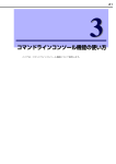
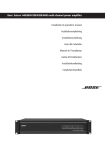
Front view
(When the front bezel and the power unit cover are opened)
1
10
2
3
5
6
4
1. Blade slot
10. Separator
From the upper left: Slot 1 – Slot 8
From the lower left: Slot 9 – Slot 16
7
8
9
A plate to separate the blade slot into the upper and
lower tier (when installing a full-height blade,
remove this plate)
2. CPU blade slot cover
A plate to cover a slot where no optional CPU
blade is installed
3. Power unit
From the left: Power unit 1 - Power unit 6
4. Power unit slot cover
A cover for a slot where no optional power unit is
installed
5. Power unit ejector
Turn this ejector and pull the handle to remove a
power unit.
6. Power unit lock
Pull this lock forward to release the lock of a
power unit ejector.
7. Power LED (green)
This LED is green when AC power is supplied.
8. Power STATUS LED (amber)
This LED is amber when an error occurs.
9. Key box
A box to fix and lock the power unit cover (can be
slid toward left and right)
22
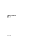
Rear view
23
2
1
3
4
5
Close-up of the EM card
7
17
11
8
8
ID
M
MNG LAN
RST
Active
9
6
10
18
12
11
12 13 14
⑬
⑥
15 16 17 18 19 20
21
13
14
15
16
22
1. Fan unit
11. Dedicated Management LAN connector (EM
card)
From the upper left: Fan unit 1 – Fan unit 5
From the lower left: Fan unit 6 – Fan unit 10
Connected to a network system that supports
10BASE-T/100BASE-TX (auto-negotiation only)
2. Fan LED
(green/amber)
12. SPEED LED (green) (EM card)
This LED is green when the status is normal. When an
error occurs, it is amber.
3. Fan unit ejector
Green when the management LAN is operating in
100BASE-TX
13.LINK/ACT LED (green) (EM card)
Pull this ejector to remove a fan unit.
Green when the management LAN connector is
connected to a network. When there is access, it
flashes green.
4. Switch module slot
From the top left: Slot 1, Slot 2
From the second tier left: Slot 3, Slot 4
From the third tier left: Slot 5, Slot 6
From the bottom left: Slot 7, Slot 8
14. RESET switch (EM card)
A switch to reboot the EM card
15. STATUS LED (green/amber) (EM card)
5. Switch module cover
A cover for a slot where no optional switch module is
installed.
6. EM card
Green when the status is normal. When an error
occurs, it is amber.
16.ACTIVE LED (green) (EM card)
Green on the active EM card. Off on the standby EM
card
From the left: EM card1, EM card 2
7. EM card slot cover
17.ID LED (blue) (EM Card)
A cover for a slot where no optional additional EM
card is installed.
8. EM card release lever
Used to identify EM card
18.Serial (COM) port (EM card)
A port to connect the EM serial console
Pull this lever forward to remove the EM card.
19. ID LED (blue) (the blade enclosure)
9. EM tray release lever
Used to identify blade enclosure
Pull this lever forward to remove the EM tray.
*This module should not be removed by anyone
except maintenance staff.
20. Power fan vent
Ejects exhaust air from a power fan
21. Power retention tie
10. AC inlet
A socket to which a power cord is connected
AC inlets correspond to the power units 1 – 6 on the
front side from right
A tie to fix a power cord
* These parts may not be installed.
22. Connector for maintenance
* These ports are for maintenance only.
23. Support stay
A plate to separate the switch module slot into the
left and right side.
23
Installation
Checking components
See the attached list to check that you have all the accessories and components.
Installing the blade enclosure on a rack
Install the blade enclosure on a rack. This section also describes how to remove the blade enclosure
as well.
WARNING
Make sure to follow the instructions and notes to use the blade enclosure and other
devices safely. There is a risk of death or serious injury. For more information, see
the descriptions on page 3.
●Do not install the blade enclosure on a nonstandard rack.
●Do not use the blade enclosure in a place other than specified.
CAUTION
Make sure to follow the instructions and notes to use the blade enclosure and other
devices safely. There are risks of a burn, injury, or damage to physical assets. For
more information, see the descriptions on page 3.
●Separate the blade enclosure into two components and carry each component with
two or more people.
●Do not install the blade enclosure in a place other than specified
●Do not use the blade enclosure with its covers and fan units removed.
●Be careful not to hurt your fingers.
●Do not impose loads on the blade enclosure while it is pulled out of the rack.
●Do not cover air vents.
Check components to install
You need the following components:
- Rail bracket (L) (1) (Shipped with the blade enclosure)
- Rail bracket (R) (1) (Shipped with the blade enclosure)
- Core nut (square hole) or clip nut (circular hole) (4) (Shipped with the blade enclosure)
Check
The shapes of rail brackets (L) and (R) are not the same. See the illustrations on the
following pages to check the locations and directions they should be installed. The
rail brackets (L) and (R) can be distinguished from each other by their marks.
24
Required Tools
A torx driver (T25) is necessary to install the blade enclosure on a rack.
Installation Procedure
Complete the following steps to install the blade enclosure on a rack. See the instructions that come
with the rack as well.
Check
Before you install the blade enclosure on a rack, remove the doors at the front
and rear of the rack. For information on removing the rack doors, see the
instructions that come with the rack.
● Check where the blade enclosure will be installed.
Attach core nuts or clip nuts as shown in the illustration below and attach the rail brackets
(L)/(R) to the rack to install the blade enclosure. Check where the blade enclosure, rail
brackets, and core nuts/clip nuts will be attached and installed.
Rack front view
Attach core nuts or clip nuts
here (four total on right and
left).
(U)
10
9
No core nuts/clip nuts
are attached on the
rear of the rack.
8
7
6
5
Attach the rail brack
et (R) here.
Blade enclosure is installed here.
4
3
2
Attach the rail brack
et (L) here.
1
0
Attach rail brackets (R)
and (L) on the rear of
the rack like the front
side.
Next to the rack holes, there are marks that are spaced by 1U (a unit to represent rack height).
Because the height of the blade enclosure is 10U (approximately 445mm), install the blade
enclosure in a space with a 10U height.
Check
Holes on the rack frame are not spaced evenly. Check that the four projections on
each rail bracket's end match with holes on the rack frame where the rail bracket is
attached before installing the blade enclosure.
25
● Attach core nuts/clip nuts.
Attach core nuts or clip nuts inlcuded with the blade enclosure at the positions determined in
"Check where the blade enclosure is installed." Attach a total of four core nuts or clip nuts on
the rack front (two each on the right and left side).
Check
Check that the core nuts/clip nuts are attached on the same height on the right and
left side of the rack.
● Attach rail brackets.
Attach rail brackets to the rack.
When you attach a rail bracket, make sure that the four projections at its bent end are inserted
into the holes on the rear frame of the rack from the outside . Slide the rail according to the
rack depth and insert the four projections on the other end into the holes on the front frame of
the rack as well. The illustration below shows how the rail bracket (R) is attached. Attach the
rail bracket (L) in the same way.
Check
Check that the rails are installed on the same level at the front and rear of the rack.
Check that the right and left rails are installed in parallel.
Rack rear
Rack front
(2)
(1)
Insert 4
projections into
the rack frame
holes.
Insert 4 projections
into the rack frame
holes.
(3)
Attaching the rail bracket (R)
● Separate the blade enclosure into two components.
Remove the rear cage from the
enclosure.
1. If any modules such as CPU blades
or power units are installed on the
blade enclosure, remove them. For
information on removing installed
modules, see their instructions for
removal.
(1)
(3)
(2)
(3)
26
2. Use a torx driver (T25) to remove
the screws at the rear of the blade
enclosure (two each on the right
and left side for a total of four),
and then bend the hinges outward
so that the rear cage will not hit
them when it is removed.
Stop lever
One each on
the right and
left side
3. Firmly hold the handles of the
blade enclosure, which are located
at its rear, on the right and left side
and slowly slide the enclosure out
approximately 10 cm. This step
should be done by two or more
people.
4. Firmly hold the handles of the rear
cage and the holding points at the
bottom (one each on the right and
left side) as shown in the right
illustration with two or more
people and pull out the rear cage
slowly until the tips of the stop
levers located at the side of the
rear cage are shown.
Holding point
(One each on the right
and left side)
5. Keep pressing the two stop levers
on both the right and left sides and
hold the handles of the rear cage
and slowly pull out the rear cage
until the stop levers are fully
shown.
6. Firmly hold the handles of the rear
cage and the holding points at the
bottom with two or more people
and slowly remove the rear cage
from the enclosure.
Important
● When you carry the rear cage, hold the two handles at the rear of the enclosure (one each on both
the right and left side) and the holding points at the bottom (one each on the right and left side).
● When you remove the rear cage, make sure not to bump or bend the connectors and pins of the
rear cage that are located at the section connecting to the enclosure (midplane) against the
enclosure or rack frame. The midplane is the board to connect the CPU blades to switch modules
or pass-through cards inside the blade enclosure.
● Do not touch any connectors and pins of the rear cage.
Hint
The rear cage is heavy, especially the side of the section connecting to the enclosure
of the blade enclosure (midplane).When you hold the holding points at the bottom to
carry the rear cage, hold the midplane side as much as possible.
27
● Install the blade enclosure on the rack.
Hold the blade enclosure with its front facing front with 2 or more people. Slowly put the
L-shaped frames on both the right and left side of the blade enclosure on the L-shaped frames
of the rail brackets that have been attached to the rack.
Important
● When you carry the enclosure, hold the four handles at both sides of the enclosure (two each
on the right and left side).
● When you install the enclosure, stow the four handles at both sides of the enclosure (two
each on the right and left side) to prevent them from bumping against the rack frames.
Check
Check that the enclosure is correctly mounted on the L-shaped frames of the rail
brackets during the installation.
Push the enclosure into the rack until it stops. Use a torx driver (T25) to tighten the front
screws of the blade enclosure (four screws, two each on the right and left) and secure the blade
enclosure to the rack.
● Install the rear cage.
Check
Before installing the rear cage, bend the hinges to the outward direction to prevent
the screws at the rear of the blade enclosure (four screws, two each on the right and
left side) from hitting the rear cage.
1. Firmly hold the handles at both
sides of the rear cage (one each on
the right and left side) and slowly
put the rear cage on the rails of the
enclosure. This step should be
done by two or more people.
Check
(1)
Check that the rear cage
is correctly mounted on
the rails of the enclosure
during the installation.
2. Push the rear cage into the
enclosure with two or more people
until it stops.
(2)
3. Bend the hinges to the inward
direction. Then, use a torx driver
(T25) to tighten the rear screws of
the blade enclosure (four screws,
two each on right and left side) and
secure the rear cage to the
enclosure.
28
Removing the blade enclosure from the rack
Follow the steps below to remove the blade enclosure from the rack.
CAUTION
Make sure to follow the instructions and notes to use the blade enclosure and other
devices safely. There are risks of a burn, injury, or damage to physical assets. For
more information, see the descriptions on page 3
● Separate the blade enclosure into two components and carry them with two or
more people.
● Be careful not to hurt your fingers.
● Do not impose loads on the top of equipment that is pulled out.
● Do not pull out equipment when the rack is not stabilized.
● Do not pull out two or more modules from the rack at the same time.
● Do not pull out the equipment from the rack while it is running.
Check
Before you remove the blade enclosure from its rack, remove the doors at the front
and rear of the rack. For information on removing the rack doors, see the instructions
that come with the rack.
1. Shut down all devices installed on the blade enclosure to power them off.
2. Disconnect the power cords of the blade enclosure and then disconnect all the interface cables.
3. Remove all modules, such as CPU blades and power units, installed on the blade enclosure. For
information on removing installed modules, see their instructions for removal.
4. Use a torx driver (T25) to remove four screws (two each on the right and left) at the rear of the
blade enclosure.
5. Slowly pull out the rear cage from the enclosure.
44
6. Firmly hold the rear cage and remove it from the enclosure.
Important
● Do not impose loads on the top of equipment that is pulled out. There is a risk of equipment
falling off.
● When you pull out the rear cage from the enclosure or carry it, firmly hold the holding points
located at the bottom (one each on the right and left) and the two rear handles (one each on
the right and left) so that you will not drop the rear cage.
7. Use a torx driver (T25) to remove four screws (two each on the right and left) on the front of the
blade enclosure.
8. Slowly pull the blade enclosure out of the rack.
Important
● Do not impose loads on the top of equipment that is pulled out. There is a risk of equipment
falling off.
● The blade enclosure has no stopper or lock mechanism that prevents it from being pulled out
of the rack. Firmly hold the handles at the bottom and sides of the blade enclosure when
removing it so you will not drop it.
29
● Hold the four handles at both sides of the enclosure (two each on the right and left) for
carrying.
9. Firmly hold the blade enclosure and remove it from the rack.
To remove any parts attached to the rack, see the description in "Installing the blade enclosure." To
install the rear cage on the enclosure, see "Installing the blade enclosure."
30
Installing a switch module or pass-through card
The following illustration shows slots where switch modules and pass-through cards can be
installed:
Slot
Slot
Slot
Slot
1
3
5
7
Slot 2
Slot 4
Slot 6
Slot 8
Install switch modules and pass-through cards according to the specifications described on the
following pages. Slots without switch modules or pass-through cards should have slot covers
installed.
31
Installable switch modules and pass-through cards
A maximum of eight switch modules and pass-through cards can be installed on this blade
enclosure (a maximum of six 4G FC switch modules (12 ports/24 ports) and FC pass-through cards
can be installed). The number and combination of switch module slots that can be used depends on
the types and combination of switch modules, pass-through cards, and mezzanine cards. For
information on communication between switch slots, standard CPU blade slots, and mezzanine
slots, see the following pages.
If there is no description for your product, contact your NEC sales representative to obtain the latest
User's Guide.
● N8406-022 1Gb Intelligent L2 Switch
● N8406-023 1Gb Intelligent L3 Switch
● N8406-016 1Gb Pass-Through Card
● N8406-019 4G FC Switch (12 ports)
● N8406-020 4G FC Switch (24 ports)
● N8406-017 FC Pass-Through Card
32
Internal connection between CPU blades and switch modules
If there is no description for the products that support your CPU blades, contact your NEC sales representative to obtain
the latest User's Guide.
CPU blade
(NEC Express5800/120Bb-6, 120Bb-d6)
Switch module slot 8
(1)
Switch module slot 7
(1)
Expansion slot 2
(For both type 1 and 2)
(4)
(3)
(2)
(1)
Switch module slot 6
(1)
Switch module slot 5
(1)
Switch module slot 4
(1)
Standard interface
(Dedicated to LAN)
1
2
Expansion slot1
(Dedicated to
Type 1)
(2)
Switch module slot 3
(1)
(1)
Switch module slot 2
(1)
Switch module slot 1
(1)
The numbers with parentheses in the figure represent port numbers of mezzanine cards or switch
modules.
(Switch module port numbers are an example when a CPU blade is installed on the slot 1.
When you install a CPU blade on the other slots, you need to replace the port number of the swi
tch modules.
Examples:
When you install a CPU blade on the slot 2, you need to replace the port number '(1)' of the
switch modules with '(2)'.
When you install a CPU blade on the slot 16, you need to replace the port number '(1)' of th
e switch modules with '(16)'.)
Because switch modules installed on the blade enclosure are shared among CPU blades, any mezzanine card with a different
interface cannot be installed on corresponding CPU blade mezzanine slots. For example, if 4G FC switches are installed on
the switch modules 3 and 4, 1000BASE-T Adapter (2ch) cannot be installed on their corresponding mezzanine slot (for
120Bb-6 and 120Bb-d6, the mezzanine slot 1).
33
When a
mezzanine
card with 4
ports is
installed.
CPU blade
(NEC Express5800/120Bb-m6)
Expansion slot 2
(For both type 1 and 2)
(4)
(3)
(2)
(1)
Expansion slot 4
(For both type 1 and 2)
(4)
(2)
(1)
(2)
(1)
Switch module
slot 8
Switch module
slot 7
(2)
(3)
(1)
(2)
(2)
(1)
(1)
Switch module
slot 6
Switch module
slot 5
(2)
Expansion slot 1
(Dedicated to type 1)
(2)
(1)
Standard interface
(Dedicated to LAN)
(1)
(2)
(3)
(4)
(1)
Switch module
slot 4
(2)
Expansion slot 3
(Dedicated to type 1)
(2)
(1)
Switch module
slot 3
(1)
(2)
Switch module
slot 2
(1)
(2)
Switch module
slot 1
(1)
The numbers with parentheses in the figure represent port numbers of mezzanine cards or switch modules.
(Switch module port numbers are examples when a CPU blade is installed on the slot 1 and 2.
When you install a CPU blade on the other slots, you need to replace the port number of the swi
tch modules.
Examples:
When you install a CPU blade on the slot 3 and 4, you need to replace the port number '(1)'
of the switch modules with '(3)', and '(2)' with '(4)'.
When you install a CPU blade on the slot 15 and 16, you need to replace the port number '(1)' of the
switch modules with '(15)', and '(2)' with '(16)'.)
Because switch modules installed on the blade enclosure are shared among CPU blades, any mezzanine card with a different
interface cannot be installed on corresponding CPU blade mezzanine slots. For example, if 4G FC switches are installed on
the switch modules 3 and 4, 1000BASE-T Adapter (2ch) cannot be installed on their corresponding mezzanine slots (for
120Bb-m6, mezzanine slot 1 and 3).
Mezzanine cards with different types (interface) cannot occupy mezzanine slots 1 and 3.
Mezzanine cards with different types (interface) cannot occupy mezzanine slots 2 and 4.
34
When
a
mezzanine
card with 4
ports
is
installed.
CPU blade
(NEC Express5800/140Ba-10)
Expansion slot 4
(For both type 1 and 2)
(4)
(3)
(2)
(1)
Expansion slot 2
(For both type 1 and 2)
(4)
(9)
(1)
(9)
(1)
Switch module
slot 8
Switch module
slot 7
(9)
(3)
(1)
(2)
(9)
(1)
(1)
Switch module
slot 6
Switch module
slot 5
(9)
Expansion slot 3
(Dedicated to type 1)
(2)
(1)
Standard interface
(Dedicated to LAN)
(1)
(2)
(3)
(4)
(1)
Switch module
slot 4
(9)
Expansion slot 1
(Dedicated to type 1)
(2)
(1)
Switch module
slot 3
(1)
(9)
Switch module
slot 2
(1)
(9)
Switch module
slot 1
(1)
The numbers with parentheses in the figure represent port numbers of mezzanine cards or switch modules.
(Switch module port numbers are examples when a CPU blade is installed on the slot 1 and 9.
When you install a CPU blade on the other slots, you need to replace the port number of the swi
tch modules.
Examples:
When you install a CPU blade on the slot 2 and 10, you need to replace the port number '
(1)' of the switch modules with '(2)', and '(9)' with '(10)'.
When you install a CPU blade on the slot 8 and 16, you need to replace the port number '(1)' of the
siwtch modules with '(8)', and '(9)' with '(16)'.)
Because switch modules installed on the blade enclosure are shared among CPU blades, any mezzanine card with a different
interface cannot be installed on corresponding CPU blade mezzanine slots. For example, if 4G FC switches are installed on
the switch modules 3 and 4, 1000BASE-T Adapter (2ch) cannot be installed on their corresponding mezzanine slots (for
140Ba-10, mezzanine slot 1 and 3).
Only when other CPU blades in the same blade enclosure have no 1000BASE-T Adapters (4ch), can you install a
mezzanine card with a different interface on the mezzanine slot 4 of the 140Ba-10.
Mezzanine cards with different types (interface) cannot occupy mezzanine slots 1 and 3.
Mezzanine cards with different types (interface) can occupy mezzanine slots 2 and 4.
(Only the combination of a 1000BASE-T Adapter (2ch) and a Fibre Channel Controller is available.)
When you use a N8406-019 4G FC Switch (12ports), a mezzanine card with 2 ports on the slot 2 or 4 of the N
EC Express5800/140Ba-10 cannot connect to the switch.
35
The following table lists mezzanine cards and their supported modules. Find your mezzanine card on the
table and check its supported module to see appropriate combinations. Before you install a mezzanine card,
check its type and number of ports to mount it on an appropriate slot.
Mezzanine card
1000BASE-T Adapter
(2ch)
(N8403-017)
1000BASE-T Adapter
(4ch)
(N8403-020)
Fibre
Channel
controller
(N8403-018)
Y: Supported
N: Not supported
Type
Number
of ports
Supported switch
module/
pass-through card
1Gb*1
FC*2
Supported CPU blade
NEC Express5800
120Bb-6
120Bb-d6
120Bb-m6
140Ba-10
1
2
Y
N
Y
Y
Y
Y
2
4
Y
N
Y
Y
Y
Y
1
2
N
Y
Y
Y
Y
Y
*1 Corresponds to 1Gb Intelligent L2 Switch (N8406-022), 1Gb Intelligent L3 Switch (N8406-023) and 1Gb Pass-Through
Card (N8406-016).
*2 Corresponds to 4G FC Switch (12ports)(N8406-019), 4G FC Switch (24ports)(N8406-020) and FC Pass-Through Card
(N8406-017).
(When a 4G FC Switch (12ports)(N8406-019) is installed, there may be restrictions in CPU blade slots which can be
connected and corresponding mezzanine slots. For information on restrictions in CPU blade slots which can be connected,
see "Installing a CPU blade." For information on restrictions in supported mezzanine slots, see the illustrations shown on
previous pages to find information on correspondence to your CPU blades.)
If there is no description for your product, contact your NEC sales representative to obtain the latest User's
Guide. Mezzanine cards that have no connection with a switch module are not listed above. In principle,
such mezzanine cards can be installed without considering the interface with other mezzanine cards. For
details, see the User's Guides and manuals of the mezzanine cards and CPU blades to be installed.
36
Alignment of switch module slots
Blade enclosure (SIGMABLADE-H)
Switch module
slot 1
Switch module
slot 2
Switch module
slot 3
Switch module
slot 4
Switch module
slot 5
Switch module
slot 6
Switch module
slot 7
Switch module
slot 8
Single-wide
Double-wide
・
・
・
・
Since a standard LAN of CPU blades is connected to slots 1 and 2, select and install 1Gb intelligent L2 switch, 1Gb intelligent
L3 switch, or 1Gb pass-through card. Other switch modules and pass-through cards, such as 4G FC switch module (12
ports/24ports) and FC pass-through card, cannot be connected.
If you use 2 switch modules or pass-through cards in the neighboring slots (slot 1 and 2, 3 and 4, 5 and 6, or 7 and 8), install
the same product.
Connection from NEC Express5800/120Bb-6, 120Bb-d6, or 120Bb-m6 to switch modules 7 and 8 can be established only
when a mezzanine card with 4 ports is installed on the mezzanine slot corresponding to the switch module.
A double-wide switch module occupies neighboring slots (slot 1 and 2, 3 and 4, 5 and 6, or 7 and 8).
37
Installing a switch module or pass-through card
Follow the steps below to install a switch module or pass-through card. A switch module or
pass-through card can be installed or removed even if the blade enclosure is powered on (switch
modules/pass-through cards in other slots are working). This section provides an example of
installation. Follow the same steps for installation on other slots.
Depending on the switch module/pass-through card type, a different operation may be required
and/or different steps may be taken. In this case, descriptions in the User's Guide of the switch
module/pass-through card should be used instead.
WARNING
Make sure to follow the instructions and notes to use the blade enclosure and other
devices safely. There is a risk of death or serious injury. For more information, see
the descriptions on page 3.
●Do not install/remove two or more switch modules/pass-through cards at the same
time.
●Do not place your hands inside the blade enclosure.
Do not remove the blade enclosure from the rack to install a CPU blade, switch
module, pass-through card, or other optional device.
Important
1. See "Installing a switch module or pass-through card" on page 31 to check the slot where the
switch module/pass-through card will be installed.
2. If the slot where you wish to install the switch module/pass-through card has a slot cover, pull
the ejector located at the upper part of the slot cover and remove the cover. In addition, when you
install a double-wide switch module / pass-through card, remove the support stay.
For safety reasons, removal of the support stay should be done only by sales maintenance
personnel. Contact your sales maintenance personnel for the removal of the support stay.
Important
● Keep the slot cover that has been removed in a safe place.
● Do not remove any slot covers and support stays other than the ones attached to
the slot where you wish to install the switch module/pass-through card.
(1)
(2)
38
3. Place the switch module/pass-through
card carefully on a clean, flat table
and open (release) the ejector. When
you open the ejector, press the stopper
locking the ejector rightward.
The illustration depicts a device with a
stopper. If there is no stopper, the
action indicated by (1) is not
necessary.
(2)
(1)
4.
Hold both sides of the switch
module/pass-through card with its ejector
side facing the top and slowly insert the
switch module/pass-through card halfway
into the blade enclosure (about 20 cm).
(2)
Important
Do not hold the ejector. Otherwise, the
ejector and the switch
module/pass-through card may be
damaged.
(1)
5. Press the frame of the module front with your thumbs with the ejector fully opened slowly into
the blade enclosure.
Push the front side of the switch module/pass-through card carefully until it is
inserted into the blade enclosure and the ejector closes slightly.
Hint
6. Close the ejector slowly.
The midplane connector of the switch module/pass-through card is connected to the midplane of
the blade enclosure.
If you cannot close the ejector successfully, check the stopper.
If you close the ejector while it is not correctly locked, the ejector or the blade enclosure may
be damaged.
39
Removing a switch module or pass-through card
Follow the steps below to remove a switch module/pass-through card.
Depending on the switch module/pass-through card type, a different procedure may be required. In
this case, follow the instructions in the User's Guide of the switch module/pass-through card
instead.
1. If any interface cables are connected to the switch module/pass-through card, remove them.
2. Open the ejector. When you open the ejector,
press the stopper locking the ejector
rightward.
The illustration depicts a switch
module/pass-through card with a stopper. If
there is no stopper the action indicated by
(1) is not necessary.
(1)
(2)
Fully open the ejector until it stops.
Check
3. Hold the ejector and pull the switch
module/pass-through card out of the blade
enclosure until you can hold its frame with
both of your hands (approximately 10 cm).
重
Important
Do not hold the ejector to remove the
switch module/pass-through card.
Otherwise, the ejector and the switch
module/pass-through card may be
damaged.
4. Firmly grip both sides of the frame of the switch module/pass-through card to remove it from the
blade enclosure.
If you want to run the system with the switch module/pass-through card removed, attach a slot
cover.
In addition, if you do not use a double-wide switch module/pass-through card for this slot, attach
a support stay.
For safety reasons, installation of the support stay should be done only by sales maintenance
personnel. Contact your sales maintenance personnel for the installation of the support stay.
5. Close the ejector of the switch module/pass-through card.
40
Installing a CPU blade
The following illustration shows slots where CPU blades can be installed:
Slot 1
Slot 9
Slot 2
Slot 4
Slot 6
Slot 8
Slot 7
Slot 3
Slot 5
Slot 10
Slot 12 Slot 14
Slot 16
Slot 15
Slot 11
Slot 13
Install CPU blades sequentially in the slots (1 to 16) in the following illustration. Install slot covers
on slots with no CPU blades. Note the following for the installation:
When you install a half-height double-wide blade, it should be installed on slots that are
neighboring horizontally with the left slot having an odd number (e.g., Slot 1 and Slot 2). Start from
a left slot with a smaller number in the following illustration. You cannot install it on horizontally
neighboring slots with the left slot having an even number (e.g., Slot 2 and Slot 3).
When you install a full-height single-wide blade, it should be installed on slots that are neighboring
vertically (e.g., Slot 1 and Slot 9). Start from an upper slot with a smaller number in the following
illustration. Blade slots are separated into blocks that are full-height and double-wide (Slots 1, 2, 9,
and 10; Slots 3, 4, 11, and 12; Slots 5, 6, 13, and 14; and Slots 7, 8, 15, and 16). You cannot have
blades of different heights in a single block. However, you can have blades with different widths in
a single block.
For information on blade sizes, see "Installable CPU blades" on page 45.
The installation procedure shown above may not apply to some module types. In this case, follow
the instructions in the User's Guides of the modules should be instead.
Slot 1
Slot 2
Slot 4
Slot 6
Slot 8
Slot 7
Slot 3
Slot 5
(1) (3) (5) (7) (9) (11) (13) (15)
(2) (4) (6) (8) (10) (12) (14) (16)
Slot 9
Slot 10
Slot 12
Slot 14
Slot 16
Slot 15
Slot 11 Slot 13
41
Important
● The CPU blade blank cover that can be installed on the blade enclosure is N8405-030.
● To install a full-height blade, remove the separator dividing the target blade slots. For safety
reasons, removal of the separator should be done only by sales maintenance personnel.
Contact your sales maintenance personnel to remove the separator.
●To install a half-height blade, a separator should be installed on the target blade slots. The
blade enclosure is shipped with separators installed.
●If one full-height blade is installed on a full-height double-wide block (Slots 1, 2, 9 and 10;
Slots 3, 4, 11, and 12; Slots 5, 6, 13, and 14; or Slots 7, 8, 15, and 16), combine 2 CPU blade
slot covers with screws (screws are shipped with CPU blade slot covers) and attach them to
the blank space of the slots. For information on the blocks, see the illustrations on the
following pages. For information on combining CPU blade slot covers to make a full-height
CPU blade slot cover, see "Assembling a full-height CPU blade slot cover."
● A half-height blade and a full-height blade cannot occupy the same block (Slots 1, 2, 9, and
10; Slots 3, 4, 11, and 12; Slots 5, 6, 13, and 14; and Slots 7, 8, 15, and 16)
● If more than one 4G FC switch (12 ports) N8406-019 is installed on the blade enclosure,
install CPU blades connected to 4G FC switch modules (12ports) according to the order
(1 3 5 . . . 13 15) shown on the previous page on the upper level of the blade
enclosure. Then, install CPU blades that are not connected to 4G FC switch modules
(12ports) according to the instructions on the previous page. 4G FC switch modules (12
ports) are connected only to the upper level of the blade enclosure.
42
Notes for installation of a half-height double-wide blade:
Slot 1
Slot 2
Slot 4
Slot 6
Slot 8
Slot 7
Slot 3
Slot 5
A
half-height
double-wide
blade can be
installed.
A half-height double-wide
blade cannot be installed
on slots starting with an
even slot number.
Slot 9
Slot 10
Slot 12 Slot 14
Slot 16
Slot 15
Slot 11 Slot 13
43
Notes for installation of a full-height and single-wide blade:
Slot 1
Slot 2
Slot 4
Slot 6
Slot 8
Slot 7
Slot 3
Slot 5
Blade slot "block"
Blocks are separated by a
non-removable frameand
are full-height and double
wide.
A half-height blade and a
full-height blade cannot
occupy the same block.
Slot 9
Slot 1
Slot 10
Slot 12 Slot 14
Slot 16
Slot 15
Slot 11 Slot 13
Slot 2
Slot 4
Slot 6
Slot 8
Slot 7
Slot 3
Slot 5
A half-height blade
can
be
installed
because it is in a
block
where
a
full-height blade is not
installed.
A
full-height
single-wide blade
can be installed.
When a full-height blade is
installed in slots 5 and 13,
a half-height blade cannot
be installed in slots 6 and
14, which are in the same
block.
Slot 9
Slot 1
Slot 10
Slot 12 Slot 14
Slot 16
Slot 15
Slot 11 Slot 13
A half-height blade
can
be
installed
because it is in a
block
where
a
full-height blade is not
installed.
Slot 2
Slot 4
Slot 6
Slot 8
Slot 7
Slot 3
Slot 5
A
full-height
single-wide blade
can be installed.
When a full-height blade is
installed in slots 5 and 13,
half-height CPU blade slot
covers cannot be installed
in slots 6 and 14, which
are in the same block.
When
a
full-height blade
is installed in
slots 3 and 11, a
full-height blade
slot cover can be
installed in slots
Slot 10
Slot 12 Slot 14
Slot 16
4 and 12, which Slot 9
Slot 15
Slot 11 Slot 13
are in the same
block.
44
Installable CPU blades
A maximum of 16 CPU blades shown below can be installed in this blade enclosure. CPU blades of
different types can be installed in one blade enclosure.
If there is no description for your product, contact your NEC sales representative to obtain the latest
User's Guide.
The following are half-height single-wide blades:
● NEC Express5800/120Bb-6
● NEC Express5800/120Bb-d6
The following is a half-height double-wide blade:
● NEC Express5800/120Bb-m6
The following is a full-height single-wide blade:
● NEC Express5800/140Ba-10
45
Installing a CPU blade
Follow the steps below to install a CPU blade. A CPU blade can be installed or removed even if the
blade enclosure is powered on (CPU blades in other slots are working).
An example of installation is provided. Follow the same steps for installation on other slots.
Depending on the CPU blade type, a different procedure may be required. In this case, follow the
instructions in the User's Guide of the CPU blade instead.
WARNING
Make sure to follow the instructions and notes to use the blade enclosure and other
devices safely. There is a risk of death or serious injury. For more information, see
the descriptions on page 3.
●
●
Important
Check
Do not install or remove two or more CPU blades at the same time.
Do not place your hands inside the blade enclosure.
Do not remove the blade enclosure from the rack to install a CPU blade, switch
module, pass-through card, or other optional module.
Before installing a CPU blade, check whether any required optional devices, such
as mezzanine cards or memory modules, are installed on the CPU blade. For
information on how to check and install optional devices, see the User's Guide of
the CPU blade.
1. See "Installing a CPU blade" on page 41 to check the slot where the CPU blade is to be
installed.
2. If the slot where you wish to install the CPU blade has a
slot cover, remove it. To remove a slot cover from the blade
enclosure, pull the upper hook and the lower stopper
forward while pressing the lower stopper from the right and
left. If a full-height CPU blade slot cover is attached, press
the upper hook on the upper level (blank slots from 1 to 8)
and the lower stopper on the lower level (blank slots from 9
to 16) forward while pressing the lower stopper on the
lower level (blank slots from 9 to 16) from the right and left
to remove it from the blade enclosure.
Important
● Keep the slot cover that has been removed in a safe
place.
● Do not remove any slot covers other than the one
attached to the slot where you wish to install the CPU
blade.
46
Remove the slot cover
while pressing the
stopper from the right
and left.
The illustration depicts a half-h
eight CPU blade.
3. If the CPU blade has any covers on the connectors on the
side that is inserted into the blade enclosure, remove them.
4. Open the CPU blade ejector. If the ejector is secured by a
screw, loosen it.
5. Hold the CPU blade with its midplane connector facing the
blade enclosure and the ejector facing down.
6. Put the end of CPU blade board on the guide rails located at
the upper and lower sides of the blade enclosure and slowly
push the CPU blade into the blade enclosure.
Check
Hint
When you insert the CPU blade into the
blade enclosure, make sure the pins on the
blade enclosure frame and the ejector of the
CPU blade fit correctly.
The ejector
down
facing
If the pins on the blade enclosure frame and the ejector of the CPU blade do not fit
correctly, move the CPU blade right and left to adjust the position.
When you install a half-height blade, a separator should be installed. When you
install a full-height blade, remove the separator if it is installed.
7. Press the ejector firmly to lock it. Tighten the screws to secure the CPU blade.
8. Write down the information of the installed CPU blade on the blade management sheet that
comes with the blade enclosure.
If a sticker is attached, write down the information on the sticker and affix it to the management
sheet. Keep the management sheet in a safe place.
47
Removing a CPU blade
Follow the steps below to remove a CPU blade.
Depending on the CPU blade type, a different procedure may be required. In this case, follow the
instructions in the User’s Guide of the CPU blade instead.
1. Shut down the OS of the CPU blade and turn the power off. For information on how to shut
down the OS of a CPU blade and how to turn the power off, see “Powering on and off a CPU
blade” and the User’s Guide of the CPU blade.
2. Loosen the screws securing the CPU blade.
3. Open the ejector to remove the CPU blade from the blade enclosure.
If you want to run the system with the CPU blade removed, attach a slot cover. When a
full-height CPU blade is removed, a full-height CPU slot cover may need to be installed on a
blank slot. For details, see “Notes for installation of a full-height and single-wide blade” in
“Installing a CPU blade.” For information on a full-height CPU blade slot cover, see
“Assembling a full-height CPU blade slot cover.”
(1)
48
(2)
Assembling a full-height CPU blade slot cover
When a full-height CPU blade is installed on a blade slot block, one full-height CPU blade slot
cover should be installed on the blank slot in the same block. By combining two half-height CPU
blade slot covers, a full-height CPU blade slot cover can be assembled. See the following
instructions to assemble a full-height CPU blade slot cover.
Important
Keep all screws.
To avoid screws and parts falling into the cabinet, device, or module,
do not assemble a full-height CPU blade slot cover near any cabinet,
device, or module.
Use one of the two CPU blade slot covers for the upper level and the other for the lower level.
Start with the CPU blade slot cover for the upper level.
1. Remove 4 screws from the right side
and 2 screws from the left side.
Right side
Left side
2. Separate the slot cover into two
components (hereafter referred to as
Part A and Part B).
Part A
Part B
The CPU blade slot cover for the upper level is now ready to be combined.
49
Move on to the CPU blade slot cover for the lower level.
3. Remove the top 2 screws from the right side.
Right side
4. Loosen the lower 2 screws on the right side
and the 2 screws on the left side.
Right side
Left side
5. Extend the CPU blade slot cover until the 2
screws on the right side line up with the
center of the elongated hole. Tighten the 4
screws to secure the blade slot cover.
To the center of
the elongated
hole
The CPU blade slot cover for the lower level is now ready to be combined.
50
6. Use the screws removed in Step 1 to connect Part B of
the CPU blade slot cover for the upper blade
(described in Step 2) to the CPU blade slot cover for
the lower level.
Part B of the CPU blade slot
cover for the upper level
CPU blade slot cover for the
lower level
7. Connect Part A of the CPU blade slot cover for the
upper level to the blade slot cover assembled in Step 6.
Part A of the CPU
blade slot cover for
the upper level
CPU blade slot cover for the
lower level
(includes Part B of the CPU
blade slot cover for the upper
level)
51
8. Use the 4 screws removed in Step 1
and 3 to fasten 4 places in the right
and left (2 each in the right and left)
to secure the blade slot covers. The
screws should be tightened at the
bottom of the elongated holes (the
position where a CPU blade slot
cover is extended most) as shown in
the figure.
Right side
Left side
Screw at the bottom of the
elongated hole
52
Disassembling a full-height CPU blade slot cover
To disassemble a full-height CPU blade slot cover into the original two CPU blade slot covers, see
the "Assembling a full-height CPU blade slot cover" and reverse the steps.
Important
Keep all screws.
To avoid screws and parts falling into the cabinet, device, or module,
do not disassemble a full-height CPU blade slot cover near any cabinet,
device, or module.
When you disassemble a full-height CPU blade slot cover into the original CPU blade slot covers,
note the following.
・ To restore the original CPU blade slot
covers, both of the blade slot covers
should be secured by screws at the top
of the elongated holes (the position
where a CPU blade slot cover is
shrunk most) as shown in the figure.
Right side
Screw at the
elongated hole
53
top
Left side
of
the
Installing the EM card
The EM card that can be installed on the blade enclosure is N8405-027.
Important
The following illustration shows where EM cards can be installed:
Slot 1
Slot 2
The EM card that is included as standard should be installed on (1) in the illustration below. If you
add another EM card, it should be installed on (2). Attach a slot cover to a slot where no EM card is
installed.
Slot 1
Slot 2
(2)
(1)
Hint
Installing another EM card on the blade enclosure in addition to the EM card
included as standard on the blade enclosure allows for auto switching between the
active and the standby EM card for redundancy functions. For details, see
"Replacing modules."
54
Installing an EM card
Follow the steps below to install an EM card. An EM card can be installed or removed even if the
blade enclosure is powered on. An example of installation is provided. Follow the same steps for
installation on another slot.
WARNING
Make sure to follow the instructions and notes to use the blade enclosure and other
devices safely. There is a risk of death or serious injury. For more information, see
the descriptions on page 3.
● Do not place your hands inside the blade enclosure.
● Do not install or remove two or more EM cards at the same time.
1. When the slot where you wish to install an EM card has a slot cover, pull the release lever
located at the top to remove the slot cover.
Important
Keep the removed slot cover in a safe place.
2. Hold the left and right sides of the EM card with the release lever side facing up and slowly
insert it into the blade enclosure.
Important
Do not hold the release lever to install the EM card. If you hold the release lever, it may
be damaged.
3. Press the frame of the EM card front with your thumbs while the release lever is fully opened to
slowly insert the EM card into the end of the blade enclosure.
Push the front side of the EM card carefully until it is inserted into the end of the
blade enclosure and the release lever closes slightly.
Hint
4. Close the release lever slowly while carefully pressing the front of the EM card. The midplane
connector of the EM card is connected to the midplane connector of the blade enclosure.
55
Removing an EM card
Follow the steps below to remove an EM card.
1. If any cables are connected to the EM card, remove them.
2. Open the release lever. When you open the
release lever, press the stopper securing the
release lever rightward.
(2)
(1)
Fully open the release lever until it stops.
Check
3. Hold the release lever and pull the EM card
out of the blade enclosure until you can
hold its frame with both of your hands
(approximately 10cm).
Important
Do not hold the release lever to remove
the EM card. If you hold the release
lever, it may be damaged.
4. Firmly grip the right and left sides of the EM card to remove it from the blade enclosure.
If you want to use the blade enclosure with the EM card removed, attach a slot cover.
5. Close the release lever of the EM card.
56
Installing a fan unit
Additional fan units are options that can be installed when more fans are needed according to the
number of CPU blades or other modules installed on the blade enclosure. See "Components"
described earlier.
Important
The fan unit that can be installed on the blade enclosure is N8405-026.
The fan unit N8405-026 is a set of two fan units.
The number of fan units required depends on the number of modules, such as CPU blades.
See "Fan unit installation guide" to add fan units as necessary. The blade enclosure is
equipped with four fan units as standard.
The following illustration shows slots where fan units can be installed:
Slot 1
Slot 6
Slot 2
Slot 7
57
Slot 3
Slot 8
Slot 4
Slot 9
Slot 5
Slot 10
Slots on which fan units are installed depend on the total number of fan units installed on the blade
enclosure. Install fan units on the slots with the "○" mark in the following illustrations according to
the number of fan units you are installing. Attach slot covers to slots with no fan units. The total
number of fan units that should be installed is determined by the number and types of modules that
are installed. For information on the number of fan units that should be installed, see "Fan unit
installation guide."
Important
Slot covers that can be installed on fan unit slots of the blade enclosure are fan slot
covers N8405-037.
When four fan units (factory default) are installed
Slot 2
Slot 4
Slot 1
Slot 3
4
Slot 5
Slot 7
Slot 9
Slot 6
Slot 8
Slot 10
When six fan units are installed (four units as factory default plus
two additional units)
Slot 2
Slot 4
Slot 1
Slot 3
Slot 5
Slot 6
Slot 7
58
Slot 8
Slot 9
Slot 10
When eight fan units are installed (four units as factory def
ault plus four additional units)
Slot 1
Slot 2
Slot 3
Slot 4
Slot 5
Slot 6
Slot 7
59
Slot 8
Slot 9
Slot 10
Fan unit installation guide
In principle, blades are installed on slots starting from the far-left slot, although there are exceptions depending
on the number and types of blades. See the User's Guides of the blades.
With four fan units (factory default), blades in section A in the following illustration (blade slots 1 and 9) can
be cooled; with six fan units, blades in sections A and B (blade slots 1 to 4 and 9 to 12) can be cooled; with
eight fan units, blades in sections A, B, and C (all blade slots) can be cooled.
When a N8406-019 4G FC switch (12 ports) is installed, up to eight CPU blades can be connected to the FC
switch (12 ports). These CPU blades are installed on the blade slots 1 to 8. CPU blades on the blade slots 9 to 16
cannot connect to a FC switch (12 ports).
When a N8406-019 4G FC switch (12 ports) is installed, full-height blades can connect to the FC switch (12
port). However, there are restrictions of mezzanine slots to which the blades can connect and slot ports. For
details, see "Internal connection between CPU blades and switch modules" on page 32.
When a CPU blade is installed on any of blade slots 5 to 8 or 13 to 16, eight fan units are required whether or
not there is CPU blade in the blade slots 1 to 4 and 9 to 12.
When the blade enclosure has a N8406-019 4G FC switch (12 ports), four blades with Fibre channel mezzanines
on the blade slots 1 to 4, and four blades without Fibre channel mezzanines on the blade slots 9 to 12, six fan
units are required for cooling.
When an even number of fan units are installed, the redundancy mode is N+1. For example, eight fans are
installed for 16 blades. If one of the fans fails (i.e., seven fans are working) successful operation can continue.
If two of the fans fail (i.e., six fans are working), operation may stop due to a temperature abnormality detected
by a server or switch module.
If only one NEC Express5800/120Bb-m6 is installed, it will use the blade slots 1 and 2 with nothing on the blade slot 9. However,
six fan units are required because the blade slot 2 is used.
When you add a fan unit, you may have to relocate fan units that are already installed. Install fan units in the correct slots by
referring to the instructions described on previous pages.
For information on the number of slots used by blade products, see "Installable CPU blades" and the User's Guides of the blades.
Slot 1
Slot 2
Slot 4
Slot 6
Slot 8
Slot 7
Slot 3
Slot 5
Slot 9
A
B
B
B
C
C
C
C
A
B
B
B
C
C
C
C
Slot 10
Slot 12 Slot 14
Slot 16
Slot 15
Slot 11 Slot 13
60
Installing a fan unit
A fan unit can be installed/removed even if the blade enclosure is powered on. The following
section is an example of installing a fan unit. Use the same method to install fan units to other slots.
WARNING
Make sure to follow the instructions and notes to use the blade enclosure and other
devices safely. There is a risk of death or serious injury. For more information, see
the descriptions on page 3.
● Do not place your hands inside the blade enclosure.
● Do not install or remove two or more fan units at the same time.
Important
The upside and downside of a fan unit are inverted on the upper level (fan unit slots 1 to 5)
and the lower level (fan unit slots 6 to 10) of the blade enclosure. Even if you attempt to
install a fan unit in the wrong direction, you cannot install it, and the connector may be
damaged.
1. If there is a slot cover on the slot where you
wish to install the fan unit, remove the slot
cover. If the slot cover is on a slot on the
upper level of the blade enclosure (fan unit
slots 1 to 5), push the slot cover ejector
upward. If the slot cover is on the lower
level (fan unit slots 6 to 10), push the
ejector downward. The illustration on the
right depicts removal from the upper level.
Push the ejector downward if you remove a
slot cover from the lower level.
Important
Keep the removed slot cover in a safe
place.
61
(2)
(1)
2. To install a fan unit on the upper level of the blade
enclosure, hold the fan unit handle and the bottom
of the unit firmly with the handle facing down and
insert the fan unit slowly into the blade enclosure
halfway (approximately 10 cm). To install a fan
unit on the lower level of the blade enclosure, hold
the fan unit handle and the bottom of the unit
firmly with the handle facing up and insert the fan
unit slowly into the blade enclosure halfway
(approximately 10 cm). The illustration on the
right depicts installing a fan unit on the upper
level. For installation on the lower level, the
fan unit is turned upside down.
Fan unit lever
Handle
Important
Do not hold the fan unit lever to install the fan unit. If you hold the fan unit lever, it may be
damaged.
3. Slowly push the fan unit handle to insert the fan unit into the blade enclosure.
Removing a fan unit
Follow the steps below to remove a fan unit:
1.
Check which fan unit you wish to remove.
2.
Hold the fan unit handle to pull the fan unit Fan unit lever
out of the blade enclosure approximately 10
cm while turning the fan unit lever leftward.
The illustration on the right depicts pulling
out a fan unit from the upper level. For
removal from the lower level, the fan unit is
(2)
turned upside down.
3.
Hold the bottom of the fan unit firmly and
remove it from the blade enclosure. If you
want to use the blade enclosure without
installing a new fan unit on the fan unit slot,
attach a slot cover.
Pull the fan
unit.
Turning the fan unit
(1)
lever leftward
Important
● Do not hold the fan unit lever to remove the fan unit. If you hold the fan unit lever, it may be
damaged.
● Turn the fan unit lever toward the indicated direction. If you turn the fan lever toward the
wrong direction, the fan lever may be damaged.
62
Installing the front bezel
The front bezel is a recommended option to protect the CPU blades installed on the blade
enclosure.
Installation and removal of the front bezel and its filter should be done only by sales maintenance
personnel. Contact your sales maintenance personnel to install or remove the front bezel and its
filter.
Important
● The front bezel that can be installed on the blade enclosure is N8405-028.
● When the front bezel is attached to the blade enclosure, a front door cannot be attached to the
rack on which the blade enclosure is installed.
Filter cleaning
The front bezel has a filter on its backside. Frequency of filter cleaning depends on how the blade
enclosure is used and the environment where the blade enclosure is installed. It is recommended to
clean the filter at least once every three months. Check the filter and clean it as necessary. Open the
front bezel and clean the filter by using a vacuum cleaner. For information on how to open the front
bezel, see "How to open the front bezel."
63
Opening the front bezel
The front bezel can be opened even if the blade enclosure is powered on. To remove a CPU blade
installed on the blade enclosure, keep the front bezel open (the front bezel is a recommended
option).
For information on how to remove a CPU blade, see "Installing a CPU blade" on page 41.
CAUTION
Make sure to follow the instructions and notes to use the blade enclosure and other
devices safely. There are risks of a burn, injury, or damage to physical assets. For
more information, see the descriptions on page 3.
Be careful not to hurt your fingers.
The following description assumes the front bezel is already attached to the blade enclosure.
1. If the front bezel is locked, insert the included key into the key slot of the front bezel and push
it lightly to unlock.
2.
Open the front bezel.
Key slot
64
Closing the front bezel
Follow the steps below to close the front bezel. The front bezel can be closed even if the blade
enclosure is powered on. Close the front bezel after installing CPU blades.
For information on installing a CPU blade, see "Installing a CPU blade" on page 41.
The following description assumes the front bezel is already attached to the blade enclosure.
1.
Close the front bezel.
Key slot
2.
If you want to lock the front bezel, insert the included key into the key slot of the front bezel
and push it lightly to lock.
65
Connecting cables
Connect cables according to the requirements of your environment. For information on connecting cables,
see the manuals of the installed devices.
Front
Use a K410-150(00) SUV cable, which is sold separately, to connect the SUV connector located
on the front side of a CPU blade to the local console.
* The SUV connector and the local console are not supported by some CPU blades. For details, see
the User's Guide of the CPU blade. Even if there is an SUV connector present, the local console
may not be supported.
The SUV cable that can be connected to a CPU blade is K410-150(00).
Important
Local console
Connect a USB keyboard to the keyboard/mouse connector of the SUV cable, and then connect a
USB mouse to the USB connector of the keyboard. The cable of the display device should be
connected to the monitor connector of the SUV cable. See the User's Guide of the CPU blade as
well.
It is assumed that the local console is used for installation of an OS and for emergency operation.
For general operation, do not use CPU blades with a SUV cable connected. Some CPU blades do
not support installation of an OS through the SUV cable. For details, see the User's Guide of the
CPU blade.
Important
● For general operation, do not use CPU blades with a SUV cable connected. If you always use
CPU blades with a SUV cable, there is a risk of damage to the SUV cable or connector.
● Make sure not to snag or pinch the SUV cable. There is a risk of damage to the SUV cable,
CPU blades and the blade enclosure, and other modules.
66
Monitor connector
SUV cable
USB connector
FDD
USB connector
(Not connected)
Serial connector
Blade enclosure
These input and output devices are collectively called "local console." CPU blades on the blade
enclosure can be directly operated when they are connected to a keyboard, video monitor, and
mouse via the SUV cable attached to the blade enclosure.
The following devices are recommended for the local console:
Note:Some CPU blades may require a local console different from the one described in this guide.
In this case, follow the instructions in the User's Guide of the CPU blade instead.
Recommended models
- 104-key Keyboard (USB) (N8870-002AF)
- Mouse (USB) (N8870-010A)
- External Floppy Disk Drive Unit (N8160-74)
67
Rear
Connect network cables (RJ-45), interface cables to be connected to switch modules, and power
cords to the rear of the blade enclosure.
EM serial console
When the serial (COM) port of an EM card is connected to a PC by a serial cable (D-Sub 9-pin
connector, crossover cable), you can operate the CPU blades and check their status.
PC
CLI
Blade enclosure
These input and output devices are called "EM serial console." You can operate and check the
status of CPU blades and other modules on the blade enclosure on a PC via the serial (COM) port.
Use a crossover cable for serial cable connection.
Use a device satisfying the following recommended specifications for the EM serial console (the
EM serial console, EM console, and LAN console can share one PC).
Recommended specifications
CPU
: Pentium processor (600MHz) or faster
Memory
: 1GB or larger
Hard disk drive : 400MB or larger
LAN
: 1 port (100Mbps or faster)
Serial
: 1 port
Recommended OS
: Windows Server 2003 Standard Edition SP1 or Enterprise Edition R2
Windows 2000 Server, Advanced Server, or Professional (SP4 or later
required)
Java Runtime Environment: JRE 1.4.2_03 recommended (contained in NEC
EXPRESSBUIDER)
Web server/servlet container: TOMCAT 4.1.29 recommended (contained in
NEC EXPRESSBUIDER)
Browser
: Internet Explorer 6.0 or later
68
EM console
When the LAN connector (management LAN connector) of an EM card is connected to a PC by a
network cable (RJ-45), you can remotely control the CPU blades. You can virtually allocate
modules, such as DVD, CD, and floppy disk drives on the PC to the CPU blades (i.e., remote
media), and operate and check the status of the CPU blades.
PC
Example of connection
ESMPRO Mg
CLI
DianaScopeMg
tftp
(Network hub)
Blade enclosure
(NTP server)
These input and output devices are collectively called "EM console" and the network is called
"management LAN." You can operate and check the status of CPU blades and other modules on
the blade enclosure on a PC via a LAN network.
Important
●The default IP address of the EM card is 192.168.1.8 ~11 (subnet mask: 255.255.255.0).
Connect to a network with a subnet mask that allows this IP address and configure the
initial settings of the network from the EM console on the same network. Then, connect to
the network you intend to use. For information on how to configure, see Initial settings in
Command-line interface (CLI) (EM card)." Make sure that there is no network device
with the same IP address as the EM card on the network.
● All EM cards have the same default IP address. Configure the IP addresses before allowing
multiple EM cards to access the same network.
● The management LAN connecter of the EM card only supports auto negotiation mode.
For the EM console, use a device whose specifications are equivalent to the device used for the EM
serial console (the EM serial console, EM console, and LAN console can share one PC).
69
LAN console
When the LAN connector of a switch module or pass-through card is connected to a PC by a
network cable (RJ-45), you can remotely control and operate CPU blades.
PC
Network Mg
ESMPRO Mg
DianaScopeMg
(Network hub)
Blade enclosure
These input and output devices are collectively called "LAN console" and the network is called
"user LAN." You can operate CPU blades and switch modules on the blade enclosure on a PC via a
LAN network.
Important
● Make sure the IP addresses have subnet masks available on the network.
● Check that the IP addresses you are configuring do not conflict with any network devices on
the network.
For the LAN console use a device whose specifications are equivalent to the device used for the
EM serial console (the EM serial console, EM console, and LAN console can share one PC).
For details on connection and how to use the LAN console, see the User's Guides and manuals of
the GbE intelligent switch (L2)(N8406-022), GbE intelligent switch (L3)(N8406-023), GbE
pass-through card (N8406-016), and CPU blades.
70
SFP connector (switch module)
See the User's Guides of the 4G FC switch (12 ports) (N8406-019), 4G FC switch (24 ports)
(N8406-020), and GbE intelligent switch (L3)(N8406-023).
SFP connector (pass-through card)
See the User's Guide of the 4G FC pass-through card (N8406-017).
71
Power connector
Connect the power cords to the AC inlets of the power units installed on the power unit slots 1 and
4 at the rear of the blade enclosure (these units are standard equipment). If any optional power units
are installed on the power unit slots 2, 3, 5, and 6, connect the power cords to the AC inlets of the
optional power units as well.
If the N+N redundant mode is set as the power redundancy mode, power units in the slots 1 to 3
form power system 1 while power units in the slots 4 to 6 form power system 2. Note this when
you connect a device such as a power supply tap or uninterruptible power supply system.
When you connect the power cords to the blade enclosure, use the cable ties that are shipped with
the blade enclosure to fix the power cords to the rack. All power cords should be fixed to the blade
enclosure by cable clamps or to power supply retention ties located near the AC inlets. Cable
clamps or cable ties are shipped with the blade enclosure. For details about installing/removing
power cords with cable clamps, see "Installing cable clamps" and "Removing a power cord form a
cable clamp". Power cords connected to the AC inlets of the power unit slots 1 to 3 should be
routed rightward horizontally and fixed to the rack by cable ties at the rear. Power cords connected
to the AC inlets of the power unit slots 4 to 6 should be routed leftward horizontally and fixed to
the rack by cable ties at the rear. Excessive force should not be applied to a spot where an AC inlet
touches a power cord.
For information on installing an optional power unit, see "Power unit" on page 81.
When AC power is supplied to a power unit, its power LED is green.
Overhead view
The illustration depicts four additional power supply units installed.
Blade enclosure
Rack frame
Rack frame
Fix to the rack frame.
Fix to the rack frame.
Fix to the blade enclosure.
72
Rear view
The illustration depicts fouraddition
al power supply units installed.
Blade enclosure
Rack frame
Rack frame
Fix to the rack frame.
Fix to the rack frame.
Fix to a blade enclosure.
Fix a power cord to a power supply retention tie
by a cable tie
Power supply
Cable tie
Draw the cable tie tip
through the cable tie hole
and then through a retention
tie hole by referring to this
illustration.
* When cable clamps are
provided as standard, use
them instead.
retention tie
Power cord
73
Installing cable clamps
Follow the steps below to install cable clamps.
1. Remove cable ties. When cable ties
are not fixed, skip this step.
When power cords are fixed to po
wer supply retention ties, remove t
he cable ties.
Power supply
retention tie
Cable tie
Power cord
2. Remove the power supply retention ties. When the blade enclosure has no power supply retenti
on ties, skip this step.
When the blade enclosure has power supply retention ties, remove them with pliers.
74
3. See the following illustrations to check where the cable clamp should be installed.
Check
The shapes of cable clamps (L) and (R) are not the same. See the following
illustrations to check the locations of the tabs on the cable clamps and the
direction in which they should be installed.
Blade enclosure (rear view)
Tab of cable clamp
Cable clamp (L)
Cable clamp (R)
For Power unit 4 - Power unit 6
For Power unit 1 - Power unit 3
75
4. Attach a cable clamp (L) to the blade encl
osure.
Clip
Place the cable clamp (L) under the power
cord and adjust the power cable to the
clip of the cable clamp.
Open the clip of the cable clamp and inser
t the power cord into the clip. Do this for
each power cord (up to three cords).
②
Bring the cable clamp to the blade enclosu
re and carefully insert the tabs of the cabl
e clamp into the slots on the blade enclos
ure.
①
You will hear a click sound when you attach the cable clamp to the blade
Check
enclosure.
Clip
5. Secure the power cords to the cable clam
p (L).
Slide the clip of the cable clamp to the en
d of the plug cap of the power cord. The
n, close both sides of the clip firmly to s
ecure the power cord. Do this for each po
wer cord (up to three cords).
6. Attach a cable clamp (R) to the blade enclosure and secure the power cords (up to three cord
s) to the cable clamp in the same way (see Steps 4 and 5).
76
Removing a power cord form a cable clamp
Follow the steps below to remove a power cord from a cable clamp.
Firmly hold the clip of the cable clamp with pliers and twist it to release the clip.
Remove the power cord.
77
Important
● Note that a maximum of 2250W/2273VA power is supplied from each power unit.
● Fix power cords firmly to the blade enclosure. If power cords are not fixed, they may be
removed while the devices are running, which can result in data loss or malfunction of the
device.
● Contact NEC's sales representative if you use an uninterruptible power supply system.
78
Emergency power off (EPO)
In of the event of an environmental disaster or problem (e.g., fire, earthquake, etc.), the emergency
power off (EPO) procedure can be performed to shut down computers, uninterruptible power
supply systems (UPS), and air conditioners to prevent further damage.
Because there is a risk of data corruption when EPO is performed, clearly define scenarios to
perform EPO in advance. Operate your system with an understanding of these scenarios and the
procedure to perform EPO.
CAUTION
Make sure to follow the instructions and notes to use the blade enclosure and other
devices safely. There is a risk of death or serious injury. For more information, see
the descriptions on page 3.
● In case of emergency, EPO should be performed quickly. Clearly define scenarios
to perform EPO in advance. Operate your system with an understanding of these
scenarios and the procedure to perform EPO.
● Place the power supply tap in a place where it is noticeable and easy to access so
that power can be shut down in an emergency.
Data may be corrupted when emergency power off is performed.
Important
Power supply tap
In case of emergency, disconnect the power cords attached to the AC inlets of the blade enclosure
from the power supply tap.
Place the power supply tap in a place where it is noticeable and easy to access so that the power
cords can be disconnected quickly.
Example: How to disconnect L6-20P power cord.
Blade Enclosure
(SIGMABLADE-H)
Power cord
(1)
Power supply tap
Power unit
(2)
Closeup
(1)
Turn the power cord plug left.
Power cord
Power supply tap
(2) Disconnect
Disconnect all power cords connected to the blade enclosure according to the illustration above.
79
Emergency power off switch
For the safety of the entire computer room, install an emergency power off switch that allows
shutdown of power supplied to all devices in the computer room in case of emergency.
This emergency power off switch should be installed near the main doorway so that an operator
can use it when he/she evacuates the room. The emergency switch should not require technical
skill or expertise to use.
80
Power unit
Additional power units are options that are installed when CPU blades and other modules on the
blade enclosure require more power units or when you want to enable power redundancy functions.
WARNING
Make sure to follow the instructions and notes to use the blade enclosure and other
devices safely. There is a risk of death or serious injury. For more information, see
the descriptions on page 3.
● Air exhausted from power fans may get hot.
Important
● The power unit that can be installed on the blade enclosure is N8405-025F.
● The number of power units required depends on the number of modules, such as CPU blades,
and the power redundancy mode selected. See "Power unit installation guide" and add power
units as necessary. The blade enclosure is equipped with two power units as standard.
The following illustration shows slots where power units can be installed:
Slot 2
Slot 4
Slot 6
Slot 3
Slot 5
Slot 1
81
The power units that are equipped as standard should be installed on (1) (there are two slots shown
as (1)). When additional power units are installed, install them in the order of (2) to (5) as shown in
the illustration below. Slots with no additional power unit installed should have slot covers attached.
For information on the number of power units required, see "Power unit installation guide."
Important
Slot covers that can be installed on power unit slots of the blade enclosure are power
slot covers N8405-036.
(1)
(2)
(4)
(1)
(3)
(5)
Slot 2
Slot 4
Slot 6
Slot 5
Slot 1
Slot 3
82
Power unit installation guide
The number of power units required is determined by the total power consumption of blades. See
the following to determine the number of power units required for your system.
*If you need more detailed information, please contact your sales agent.
1. Calculate the total power consumption according to the following formula:
Total power consumption (watt) = total power consumption of blades (watt) + 1340 (watt) (power
consumption of the blade enclosure*)
*The power consumption of the blade enclosure includes power consumption of switch modules, fan units, etc.
To find the total power consumption of the blades, add up the power consumption of all the blades installed on the
blade enclosure. The amount of power consumption varies according to the blade type. For information on the power
consumption of blades, see the User's Guides or Configuration Guides of the blades.
2. Determine the number of power units required by using the value for total power consumption
quoted by the formula above.
Number of power
units required
Total power
consumption (watt) (N+1 redundancy
mode)
Number of power
units required
(N+N redundancy
mode)
2250 or smaller
2
2
4500 or smaller
6750 or smaller
9000 or smaller
3
4
5
4
6
Not available
Remarks
The number of power units required
include the two power units that are
installed as standard.
As of 2008 April
Important
The N+N redundant mode cannot be used if the total amount of power consumption
is over 6750 watts. Use the N+1 redundant mode instead.
83
Installing a power unit
Follow the steps below to install a power unit. A power unit can be installed or removed even if the
blade enclosure is powered on. Power units can be removed only in a redundancy configuration. If
you want to remove a power unit in a non-redundancy configuration, power off all devices on the
blade enclosure. Installation can be done in both redundancy and non-redundancy configurations.
An example of installation is provided below. Follow the same steps for installation on other slots.
WARNING
Make sure to follow the instructions and notes to use the blade enclosure and other
devices safely. There is a risk of death or serious injury. For more information, see
the descriptions on page 3.
Do not place your hands inside the blade enclosure.
Do not insert a wire or metal object.
1. Check that the AC inlet corresponding to the slot on where you to install a power unit has a
power cord connected. If not, connect a power cord.
2. If the power unit is installed on the slot 3 or 4, slide the key box so that it will not impair the
installation. For information on moving the key box, see "Moving the key box."
3. If the slot on which you are installing
the power unit has a slot cover,
remove it.
Pull the slot cover hook forward.
Important
● Keep the slot cover that has been removed in a safe place.
● Do not remove any slot covers other than the one attached to the slot where you
wish to install the power unit.
4. Put the power unit on a clean, flat
table and open the power unit ejector.
When you open the power unit ejector,
push the power unit stopper securing
the power unit ejector downward.
(2)
(1)
84
5. Hold the power unit frame with the power unit stopper facing up. Push the frame at the front of
the power unit and slowly insert the power unit into the blade enclosure.
Important
Do not touch the plug terminals of the power unit. Do not insert a wire or metal object. Do not
let dust or waste enter the power unit.
6. Close the power unit ejector.
Removing a power unit
Follow the steps below to remove a power unit:
1. Check which power unit you wish to remove.
2. If the power unit you wish to remove is in the slot 3 or 4, slide the key box so that it will not
impair removal. For information on moving the key box, see "Moving the key box."
3. If the power units are not in a redundancy configuration, power off all the CPU blades that are
installed on the blade enclosure.
Important
To remove a power unit in a non-redundant configuration, power off all devices in the blade
enclosure.
4. While releasing the power unit stopper
by pushing it down, pull the power unit
ejector forward. Release the stopper
and hold the ejector to pull out the
power unit about 20 cm.
5. If the fan in the power unit is still working, wait until it stops.
(2)
(1)
6. Hold the power unit ejector and the bottom of the frame, and slowly remove the power unit
from the blade enclosure.
If you want to use the blade enclosure with the power unit removed from the slot, attach a slot
cover to the slot.
85
Power unit cover
Opening the power unit cover
The power unit cover can be opened even if the blade enclosure is powered on. When you install or
remove a power unit, keep the power unit cover open. If you keep using the system, close the
power unit cover.
For information on how to remove a CPU blade and a power unit, see "Installing a CPU blade"
on page 41 and "Power unit" on page 81, respectively.
CAUTION
Make sure to follow the instructions and notes to use the blade enclosure and other
devices safely. There are risks of a burn, injury, or damage to physical assets. For
more information, see the descriptions on page 3.
Do not use the blade enclosure with its covers and fans removed. If you use the
blade enclosure without them, the cooling efficiency inside the blade enclosure
degrades, causing malfunction. Also, dust may get in and cause a fire or electric
shock.
Be careful not to hurt your fingers.
1. If the optional front bezel is attached, open the front bezel. For information on opening the
front bezel, see "Installing the front bezel."
2. If the power unit cover is locked, insert the included key into the key slot of the power unit
cover to unlock it.
3. Open the left door of the power unit cover.
4. Open the right door of the power unit cover.
(1)
86
Key slot
(2)
Closing the power unit cover
The power unit cover can be closed even if the blade enclosure is powered on. After installing the
power units, close the power unit cover.
For information on how to install a CPU blade and a power unit, see "Installing a CPU blade" on
page 41 and "Power unit" on page 81, respectively.
1. If the key box is not located at the key slot
of the power unit cover, slide the key box
to place it in an appropriate position. For
information on how to move the key box,
see "Moving the key box."
2. Close the right door of the power unit
cover.
3. Close the left door of the power unit cover.
(2)
(1)
Key slot
4. If you want to lock the power unit cover, insert the included key into the key slot of the power
unit cover to lock it.
5. If the optional front bezel is attached, close the front bezel. For information on closing the front
bezel, see "Installing the front bezel."
Moving the key box
Follow the steps below to move the key box. The key box is used to fix and lock the power unit
cover. You can slide it right/leftward as necessary when you are installing or removing a power
unit.
1. Press the key box lock.
2. Slide the key box
rightward or leftward to
an appropriate position
while pressing the lock.
Key box
(2)
3. Release the key box lock.
(1)
Lock
Push up the lock to release the
key box and move it rightward or
leftward.
87
Power on and off
Powering on and off the blade enclosure
WARNING
Make sure to follow the instructions and notes to use the blade enclosure and other
devices safely. There is a risk of death or serious injury. For more information, see
the descriptions on page 3.
● Do not place your hands inside the blade enclosure.
Important
Make sure to follow the instructions to power on and off devices. If you do not
follow the instructions, data may be corrupted or the devices may malfunction.
Powering on and off the blade enclosure without uninterruptible power supply
system (UPS).
This section describes how to power on and off a blade enclosure that is connected to the power
distribution board via a power supply tap.
Depending on the types of modules and units and how they are used on the blade enclosure, a
different procedure may be required. In this case, follow the instructions in the User's Guides of the
modules and units instead.
To power on the blade enclosure, power on the power distribution board to which the power supply
tap is connected.
To power off the blade enclosure:
1. Shut down all the CPU blades and power them off.
2. Power off the power distribution board to which the power supply tap is connected.
88
Powering on and off the blade enclosure with uninterruptible power supply
system (UPS).
Follow the steps below to power on the blade enclosure using an uninterruptible power supply
system (UPS). When you use a UPS, contact your NEC sales representative.
Depending on the types of modules and units and how they are used on the blade enclosure, a
different procedure may be required. In this case, follow the instructions in the User's Guides of the
modules and units instead.
1. Power on the power distribution board to which the UPS that is installed on the rack is
connected.
2. Power on the UPS that is installed on the rack.
Follow the steps below to power off the blade enclosure.
Depending on the types of modules and units and how they are used on the blade enclosure, a
different procedure may be required. In this case, follow the instructions in the User's Guides of the
modules and units instead.
1. Shut down all the CPU blades and power them off.
2. Power off the UPS on the rack.
3. Power off the distribution board to which the UPS on the rack is connected.
89
Powering on and off a CPU blade
There are four ways to power on and off the CPU blades installed on the blade enclosure. Power on
the video monitor and other connected devices and then power on the CPU blades in one of the
following ways. For information on the CPU blades, including their behavior after power-on and
checking the behavior, see the User's Guides and manuals of the CPU blades.
Note:
Some CPU blades require different procedures, in which case the instructions in the
User's Guides of the CPU blades should be followed. Some CPU blades may not
support all the methods to power on/off described here. For details see the User's
Guides and manuals of the CPU blades.
Important
Check
Before powering on a CPU blade, the EM card should be started whether the CPU
blade is started by its power switch or remotely. If you attempt to power on a CPU
blade before the EM card is started, the CPU blade may not be powered on. In this
case, check to see the EM card is started, and then power the CPU blade on by its
power switch.
If the blade enclosure cord is connected to any power control system such as an
uninterruptible power supply (UPS) system, confirm that the power control system is
powered on.
Hint
It will take a while to start up EM cards. By logging on to an EM card from a CLI and
checking the status of all the CPU blades on the blade enclosure by the SHOW SERVER
LIST command, you can see whether or not the EM card is started. There may be a CPU
blade status indication "unknown" or EM card not started up. For information on the SHOW
SERVER LIST command, see "Commands."
To start up the OS from a peripheral device that is connected to a switch module or
pass-through card, such as storage, power-on should be done in the order starting from
peripheral device (storage), then the switch module/pass-through card, and then the CPU
blade. Confirm that a module is fully started before you power on the next module or device.
90
Powering on and off a CPU blade by its power switch
A CPU blade on the blade enclosure can be powered on and off by using the power switch located
on the front of the CPU blade. For details, see the User's Guide and manuals of the CPU blade.
When a CPU blade is powered on by its power switch, the DC power supply from power units on
the blade enclosure starts. Then the power LED of the CPU blade turns green, showing the CPU is
now powered on.
When you either press the power switch of the CPU blade or perform OS shutdown to power off
the CPU blade, the power LED of the CPU blade turns amber, showing the CPU blade is powered
off.
Power
LED
Power
switch
Example of NEC Express5800/120Bb-6.
The location of the LED and switch depends on the CPU
blade. For more information, see the User's Guide and
manual of the CPU blade.)
Powering on a CPU blade by the blade enclosure
Functions to automatically power on CPU blades on the blade enclosure when the blade enclosure
is powered on are provided. The functions can be enabled by configuring a target CPU blade. If the
CPU blade is configured to disable the functions, the CPU blade is not automatically powered on.
In this case, power on the CPU blade by using its power switch or change its configuration. For
details, see the User's Guide of the CPU blade.
Powering on a CPU blade via a network (switch module/pass-through
card)/serial connector (CPU blade)
A CPU blade on the blade enclosure can be powered on and off by a network connected to the
LAN connector of a switch module/pass-through card on the blade enclosure or the serial connector
of the SUV cable connected to the CPU blade. For details, see the User's Guides of the CPU blade
and switch module/pass-through card.
Hint
By configuring the BIOS settings of the CPU blade, auto power-on by receiving
packets over a network or via a modem connected to the serial connector of a
SUV cable is enabled. Configure the Wake On Events settings of System
Hardware in the BIOS SETUP utility. For details, see the User's Guide of the
CPU blade.
To power on or off a CPU blade from a network connected to the LAN connector
of a switch module/pass-through card, the switch module/pass-through card
should be started up.
91
Powering on a CPU blade by the network serial (COM) port of an EM card
A CPU blade on the blade enclosure can be powered on and off by a network connected to the
management LAN connector of the EM card or the serial port (COM) of the EM card. For details,
see the User's Guide of the CPU blade.
This section describes how to power on and off a CPU blade by a CLI from the EM serial console
or the EM console. For information on other ways to power on and off, see the User's Guide of the
CPU blade. For details of CLI, see "Command-line interface (CLI) (EM card)" and "Command
input Specifications." For information on the EM serial console and the EM console, see
"Connecting cables."
Check
Powering on and off of a CPU blade by a CLI should be done by "Administrator" or
a user with the ADMINISTRATOR or OPERATOR access right.
Follow the steps below to power on a CPU blade from a CLI:
1. Confirm that the EM card is powered on.
2. From the CLI of the EM serial console or the EM console, confirm that you have logged on as
"Administrator" or a user with the ADMINISTRATOR or OPERATOR access right. If you
have not, log on as "Administrator" or a user with the ADMINISTRATOR or OPERATOR
access right.
3. From the CLI, run the following command for powering on a specified CPU blade. For details,
see "Commands."
POWERON SERVER <Slot number>
Follow the steps below to power off a CPU blade from a CLI:
1. Confirm that the EM card is powered on.
2. From the CLI of the EM serial console or the EM console, confirm that you have logged on as
"Administrator" or a user with the ADMINISTRATOR or OPERATOR access right. If you
have not, log on as "Administrator" a or user with the ADMINISTRATOR or OPERATOR
access right.
3. From the CLI, run the following command for powering off a specified CPU blade. For details,
see "Commands."
POWEROFF SERVER <Slot number>
Follow the steps below to restart a CPU blade from a CLI.
1. Confirm that the EM card is powered on.
2. From the CLI of the EM serial console or the EM console, confirm that you have logged on as
"Administrator" or a user with the ADMINISTRATOR or OPERATOR access right. If you
have not, log on as "Administrator" or a user with the ADMINISTRATOR or OPERATOR
access right.
92
3. From the CLI, run the following command for restarting a specified CPU blade. For details, see
"Commands."
REBOOT SERVER <Slot number>
93
Memo
94
Memo
95
96
Command-line interface (CLI) (EM card)
A command-line interface (CLI) allows configuring and managing the modules installed on the
blade enclosure, including CPU blades and switch modules.
A CLI can be used on the EM serial console and the EM console.
Connecting a cable to a console
For information on how to connect a cable, refer to "EM serial console (serial connection)" and
"EM console (Telnet connection)."
Starting a console
There are three ways to use a CLI.
In any of the three ways, a CLI becomes available by entering a user name and a password from a
command prompt after the CLI is successfully connected. For details, refer to "Command input
Specifications."
To log out, type EXIT on the CLI (you can also log out by typing LOGOUT or QUIT).
Check
Hint
If you are using a CLI for the first time, only "Administrator" can use the CLI.
It is needed to register users other than "Administrator" to use the CLI. For
information on how to register user names for CLI, refer to "Initial settings."
A default password for "Administrator" is printed on the label of an EM card or
the release lever. Each EM card has a different default password for
"Administrator."
Use UTF-8 encoding as a character set of the terminal emulator software. If you
use other encoding, some of the letters may be displayed incorrectly.
If you cannot enter a command while operating a CLI because the window is not
properly displayed, restart the terminal emulator software or terminate the CLI and
reconnect it.
EM serial console (serial connection)
You can use a CLI from the EM serial console. Install terminal emulator software that supports a
serial port connection on a PC. Terminal emulator software supporting the serial port is necessary
for the EM serial console. For settings of the software, refer to the manual of the software.
Configure the parameters of the serial cable connection as follows:
― Serial cable connection parameters
Transfer rate
Data length
Parity
Stop bit
Flow control
: 115200 bps
: 8 bit
: None
: 1 bit
: None
97
EM console (Telnet connection)
You can use a CLI via a telnet connection from the EM console. Install terminal emulator software
supporting telnet. For settings of the terminal emulator software, refer to the manual of the
software.
To check if the telnet function is enabled, execute the SHOW NETWORK
command (the telnet function is enabled by default). If the function is disabled,
execute the ENABLE TELNET command to enable the telnet function. For details on
each command, refer to "Commands."
Hint
― Telnet connection parameter
TCP port
Check
Important
:23
The default value of the IP address of an EM card is 192.168.1.8~11 (subnet mask:
255.255.255.0). When connecting to an EM card from the EM console for the first
time, connect to 192.168.1.8
Log in from a secure network because the password is transmitted without
encryption.
EM console (SSH connection)
You can use a CLI via a SSH connection from the EM console. Install terminal emulator software
that supports SSH. For settings of the terminal emulator software, refer to the manual of the
software.
Execute the SHOW NETWORK command to check if the SSH function is enabled
(the SSH function is enabled by default). If the function is disabled, execute the
ENABLE SECURESH command to enable the SSH function. For details on each
command, refer to "Commands."
Hint
― SSH connection parameters
TCP port
: 22
SSH version
: SSH2
Check
The default value of the IP address of an EM card is 192.168.1.8~11 (subnet mask:
255.255.255.0). When connecting to an EM card from the EM console for the first
time, connect to 192.168.1.8
98
Initial settings
Configure the initial settings of modules installed on the blade enclosure, such as EM cards and
CPU blades, by using the EM serial console or EM console. For connections and settings of the EM
serial console and the EM console, refer to "Connecting cables."
Check
The default password for "Administrator" is printed on the label of an EM card
or the release lever. Each EM card has a different default password for
"Administrator."
Configure the initial settings by "Administrator" or a user whose access right is
"Administrator" or "Operator." Some initial settings can only be changed by
"Administrator" or a user whose access right is "Administrator."
Configure the initial settings from the active EM card. For more information on
active EM card, refer to "EM card" on page 123.
The default value of the IP address of an EM card is 192.168.1.8 ~ 11 (subnet
mask: 255.255.255.0). When connecting to an EM card from the EM console
for the first time, connect to 192.168.1.8
Date and time settings (EM card)
1. Confirm that the EM card is powered on.
2. Confirm that you have logged in as "Administrator" or a user whose access right is
"ADMINISTRATOR" or "OPERATOR" from a CLI of the EM serial console or EM console.
If you have not, log in as "Administrator" or a user whose access right is
"ADMINISTRATOR" or "OPERATOR."
3. Configure the following information by running commands on the CLI. For details, refer
to"Commands."
― Changing date settings (required when not using the NTP function)
Configure the date and time of an EM card.
SET DATE <MMDDhhmm({CC}YY)> <time zone>
- MM: month DD: date hh: time mm: minute CCYY: Christian era year
- time zone: refer to "Time zone" in "Appendix." The default value is JST.
― Configuring an NTP server
To use the NTP function, you must configure the primary NTP server setting and
ENABLE NTP; configuring the secondary NTP server is optional.
Set up the NTP server for the EM card.
Before you do so, you must complete "Network settings (EM card)" on page 103
(it takes about 5 seconds for the command to complete).
SET NETWORK NTP PRIMARY <primary NTP server address>
(SET NETWORK NTP SECONDERY <secondary NTP server address>)
SET TIMEZONE <time zone>
- Time zone: refer to "Time zone" in "Appendixes." The default value is JST.
ENABLE NTP
4. Execute the command below on the CLI to check that the settings you made have taken effect.
For details, refer to "."
When the date and time settings have been modified, run the SHOW DATE command.
When the NTP server settings have been configured, run the SHOW NETWORK
99
command.
User settings (EM card)
1.
Confirm that the EM card is powered on.
2.
Confirm that you have logged in as "Administrator" or a user whose access right is
ADMINISTRATOR or OPERATOR from a CLI of the EM serial console or EM console. If
you have not, log in as "Administrator" or a user whose access right is ADMINISTRATOR or
OPERATOR.
3.
Configure the following information by running commands on the CLI. For details, refer to
"Commands."
― Changing the password of Administrator (highly-recommended)
Change the password of Administrator.
The password can contain three to eight alphanumeric characters (the first character must
be a letter).
Do not forget the password of Administrator.
If you forget, password recovery is necessary. For information on how to recover a
password, refer to "Password recovery" on page 119.
SET PASSWORD
New Password : ******** (Type a password)
Confirm
: ******** (Type the same password)
― Registering regular users. When adding a user, ADD USER is required. FULL NAME
is optional.
Register regular user accounts as necessary.
ADD USER <user name (within 13 characters)>
New Password : ******** (Type password)
Confirm
: ******** (Type the same password)
SET USER FULLNAME <user name> <full name (within 32 characters)>
― Configuring the access right of the regular users (optional)
Configure the access right of the regular users. The default value of access right of a
regular user is USER.
SET USER ACCESS <user name> [ADMINISTRATOR | OPERATOR | USER]
When two EM cards are installed and you configure the password of the regular users or
Administrator on the active EM card, the same values are automatically allocated to the standby
EM card. For details of the active EM card, refer to "EM card" on page 123.
Hint
4.
Execute the command below on the CLI to check that the settings you made have taken effect
For details, refer to "Commands."
When you addeusers or change the access rights, run the SHOW USER <user name>
command.
100
Rack settings (EM card)
1. Confirm that the EM card is powered on.
2. Confirm that you have logged in as Administrator or a user whose access right is
ADMINISTRATOR or OPERATOR from a CLI of the EM serial console or EM console. If
you have not, log in as "Administrator" or a user whose access right is ADMINISTRATOR or
OPERATOR.
3. Configure the following information about the rack by running commands from the CLI. For
details, refer to "Commands."
― Rack name (required for report processing)
Configure the name of the rack on which the EM card is installed (up to 32 characters).
Specify any unique name to identify the rack.
SET RACK NAME <rack name>
― Rack ID (Optional)
Configure a unique ID of the rack on which the EM card is installed (up to 16 characters).
Specify any unique ID to identify the rack. Do not configure the same ID as another rack.
Only alphanumeric characters can be specified for the ID (the first character must be a
letter)
SET RACK UID <rack ID>
4. Execute the command below on the CLI to check that the settings you made have taken effect.
For details, refer to "Commands."
When the name of the rack has been configured, execute the SHOW RACK NAME
command.
When the ID of the rack has been configured, execute the SHOW RACK UID command.
Blade enclosure settings (EM card)
1. Confirm that the EM card is powered on.
2. Confirm that you have logged in as Administrator or a user whose access right is
ADMINISTRATOR or OPERATOR from a CLI of the EM serial console or EM console. If
you have not, log in as "Administrator" or a user whose access right is ADMINISTRATOR or
OPERATOR.
3. Configure the following information about the blade enclosure by running commands on the
CLI. For details, refer to "Commands."
101
― Blade enclosure name (required for report processing)
Configure the name of the blade enclosure on which the EM card is installed (up to 32
characters).
Specify any unique name to identify the blade enclosure.
SET ENCLOSURE NAME <the blade enclosure name>
― Blade enclosure asset number (optional)
Configure an asset number of the blade enclosure on which the EM card is installed (up to
32 characters).
Configure any asset number of the blade enclosure, such as a number allocated for
managing assets in your organization.
SET ENCLOSURE ASSET TAG <the asset number>
4. Execute the command below on the CLI to check that the settings you made have taken effect.
For details, refer to "Commands."
When the name or asset number of the blade enclosure has been configured, execute the
SHOW ENCLOSURE INFO command.
102
Network settings (EM card)
1. Confirm that the EM card is powered on.
2. Confirm that you have logged in to the EM card as Administrator or a user whose access right
is ADMINISTRATOR or OPERATOR from the CLI of the EM serial console or EM console.
If you have not, log in as "Administrator" or a user whose access right is ADMINISTRATOR
or OPERATOR.
3. Determine the network configuration.
Important
- Confirm in advance that IP addresses to be configured are available in your network. When IP
address or subnet mask settings are lost after the configuration, reconfigure them on the EM
serial console.
- IP addresses should have a subnet address that is available in your network. IP addresses of
EM cards, CPU blades ,and switch modules must have a common subnet mask. Configure IP
addresses with the same subnet in advance.
- Confirm that the IP addresses do not conflict with the IP addresses of other machines on your
network.
- Configure a unique IP address for each module installed on the blade enclosure. Even when
you operate the blade enclosure with some modules powered off, all the modules installed on
the blade enclosure must have unique IP addresses. Pay attention when you configure the IP
addresses of modules without using the DHCP function. If you are using modules for the first
time, all of them may have the same IP address configured. In this case, you must reconfigure
each one to have a unique IP address.
- When an IP address is configured, consecutive numbers are automatically allocated for the IP
addresses of EM cards and CPU blades/switch modules for management LAN. Ensure that
none of the IP addresses conflict. Not only the first IP address but also automatically-allocated
IP addresses must be within an appropriate range.
- A floating IP is an IP address that dynamically switches according to the status of the EM card
(active/standby). Regardless of where the EM card is physically stored, if the EM card is
active, a floating IP (active EM) is allocated, and if the EM card is stand-by, a floating IP
(stand-by EM) is allocated. When the status of the EM card switches to active/stand-by due to a
failure on the EM card or the FORCE TAKEOVER command, the floating IP is automatically
switched. By using a floating IP, you can use active EM (or stand-by EM) while where the EM
card is physically stored remains transparent. For detailed information on active EM card etc.,
refer to "EM card" on page 122.
- A static IP address (EM card slot 1/2) is an IP address that is determined depending on where
the EM card is physically stored (the left is EM card slot 1, the right is EM card slot 2). A static
IP address is not affected by whether the status of EM card is active or stand-by.
103
― Configuration example
The following is an example. Configure each IP address and subnet mask according
to your usage environment.
(1) EM card -network configuration
Floating IP
192.168.1.4
(active EM)
Floating IP
192.168.1.5
(stand-by EM)
Static IP address
192.168.1.6
(EM card slot 1)
Static IP address
192.168.1.7
(EM card slot 2)
Four
consecutive
IP
addresses
Specify the IP address of
floating IP (active EM)
(2) CPU blade (Slot 1~16) -network configuration
192.168.1.8
Slot1
Slot2
192.168.1.9
Slot3
192.168.1.10
Slot16
192.168.1.23
(3) Switch module (Slot1~8) -network configuration
Slot1
192.168.1.24
Slot2
192.168.1.25
Slot3
192.168.1.26
Slot8
24
consecutive
IP
addresses
Specify the IP address of
CPU blade (slot 1)
192.168.1.31
(4) Configuration of subnet mask and gateway (this configuration is used across EM
cards, CPU blades, and switch modules)
Subnet mask
255.255.255.0
Gateway
192.168.1.99
(5) Configuration of DNS server (this configuration is used across EM cards, CPU
blades. and switch modules)
Primary DNS
192.168.1.111
Secondary DNS
192.168.1.123
4. Configure the following information by executing the commands on a CLI. For details, refer to
"Commands."
Check
If you change the IP address of the EM card while you are using a CLI on the EM
console, the EM console is disconnected from the EM card. Change the target IP
address of the terminal emulator of the EM console to the new IP address of the
EM card to log on again. Depending on the new IP address of the EM card, the
network configuration of the EM console and other network machines must be set
to the appropriate values in advance.
― Each IP address setting (required)
Configure the network settings of EM cards, CPU blades, and switch modules
(it takes about 5 seconds for the command to complete).
SET NETWORK ADDRESSRANGE <the IP address of the floating IP
(active EM)> <the IP address of CPU blade (Slot1)> <subnet mask>
Example SET NETWORK
255.255.255.0
ADDRESSRANGE
104
192.168.1.4
192.168.1.8
When you are using DianaScope, the last numeric value of the IP address of a
floating IP (active EM) must be multiples of 4 (e.g., 192.168.1.4 and 192.168.1.8).
Important
Hint
By specifying a floating IP (active EM) by the SET NETWORK
ADDRESSRANGE command, consecutive numbers are automatically
allocated to IP addresses of the floating IP (standby-EM), static IP address (EM
card slot 1), and static IP address (EM card slot 2). Reserve four consecutive IP
addresses in advance.
By specifying the IP address of the CPU blade (slot 1) by the SET NETWORK
ADDRESSRANGE command, consecutive numbers are automatically
allocated to the IP addresses of the CPU blades (Slot2~16) and switch modules
(Slot1~8). Reserve twenty-four consecutive IP addresses in advance.
"Consecutive numbers" means values consecutive by the decimal number (e.g.,
"10.0.0.254" and "10.0.0.255" are "consecutive numbers" but "10.0.0.255" and
"10.0.1.0" are not).
Some modules might not support or may disable the DHCP client function. In
this case, the IP address that is configured using the SET NETWORK
ADDRESSRANGE command is not allocated to a module. Configure each IP
address on the module or enable the DHCP client function if it is disabled. For
details, refer to the User's Guide of the module. Some modules do not require
IP address configuration.
It may take a couple of minutes for a module to acquire an IP address
configured by the SET NETWORK ADDRESSRANGE command. Use the
SHOW SERVER LIST command and the SHOW SWITCH INFO command
for CPU blades and switch modules respectively to check that the module has
acquired the configured IP address. For more information on the commands,
refer to "Commands."
It may take some time until the IP address is reflected in the switch module by
the DHCP function after performing the SET NETWORK ADDRESS RANGE
command. In this case, restart the switch module. Then, the IP address
configured by an EM card is allocated to the switch module.(For information on
how to restart a switch module, refer to RESTART SWITCH command of
"Commands" or the User's Guide of the switch module. For a CPU blade, if
the settings are changed, a process to reallocate an IP address is executed so
that the new IP address is set after a while. However, if the User's Guide of the
CPU blade has different instructions, follow those instructions.
When setting the DHCP function on a module to enabled or disabled, it may
take a couple of minutes for the module to acquire an IP address which is set by
the SET NETWORK ADDRESS RANGE command. If the IP address is not
allocated to the module after a while, restart the EM card by performing the
"RESTART EM" command on a CLI.
The IP address allocated to each module by the SET NETWORK
ADDRESSRANGE command is enabled in the management LAN. For settings
of IP addresses on the user LAN, see the User's Guides of your blade and
switch modules.
The IP address configured by the SET NETWORK ADDRESSRANGE
command is reserved for a slot if there is no module on the slot or a module on
the slot does not require IP address settings. It is recommended not to configure
the same IP address as the reserved one for any other network machine.
Generally, a pass-through card is a module that does not require IP address
settings. Depending on the pass-through card, you may find a different
description from the one in this manual in the User's Guide of the pass-through
card.
― Default gateway settings (required when using default gateway)
Configure a default gateway
105
(it takes about 5 seconds to complete the command).
SET NETWORK GATEWAY <Gateway IP address>
(Example) SET NETWORK GATEWAY 192.168.1.99
― DNS configuration (required to register one or more DNS server when the DNS
function is used)
Register a DNS server.
By default, the DNS server configured first is "primary."
It is possible to delete a registered DNS server by the REMOVE NETWORK DNS
command. After deleting the primary or secondary DNS address, the ADD NETWORK
DNS command sets a primary or secondary DNS address, respectively. If you delete
both of the primary and the secondary and run the ADD NETWORK DNS command,
they are configured in the order of primary and secondary. For information on the
REMOVE NETWORK DNS command, refer to "Commands.")
(ADD NETWORK DNS <primary DNS server>)
(ADD NETWORK DNS <secondary DNS server>)
(Example)
ADD NETWORK DNS 192.168.1.111
ADD NETWORK DNS 192.168.1.123
The default gateway and DNS server (primary, secondary) are used across EM
cards, CPU blades, and switch modules.
Hint
5. Run the following command from the CLI to check that the changes have taken effect:
Confirm the network configuration by using the SHOW NETWORK command.
6. Restart the EM card if necessary. For information on how to restart an EM card, refer to
"RESTART EM" in "Commands."
Important
Check
Do not install/remove a module or power on/off a module while restarting the EM
card. Doing so might result in not only failure to complete the configuration update
but malfunctions of the module. Do not switch on/off the ID LED of an installed
module. The ID LED may not be appropriately turned on/off.
It is required to restart the EM card after changing the DNS and default gateway
configuration (the changes take effect after the EM card is restarted).
SNMP settings (EM card)
1.
Confirm that the EM card is powered on.
2.
Confirm that you have logged in to the EM card as Administrator or a user whose access right
is ADMINISTRATOR or OPERATOR from the CLI of the EM serial console or EM console.
If you have not, log in as "Administrator" or a user whose access right is ADMINISTRATOR
106
or OPERATOR.
3.
Run the following commands from a CLI to configure settings. For details, refer to
"Commands."
― Configuring community name
To use the SNMP function, the write community setting is required. Read and trap
community settings are optional.
Configure community names (the default community name value for read, write, and
trap operations is "public").
SET SNMP COMMUNITY READ <the community name that allows a read
operation>
SET SNMP COMMUNITY WRITE <the community name that allows a write
operation>
SET SNMP COMMUNITY TRAP <the community name that allows a trap
operation>
― Configuring contact name (optional)
Configure a SNMP contact name.
Configure the contact address on SNMP (e.g., the address of the server room where the
rack is located).
SET SNMP CONTACT <the contact name>
― Location information setting (required to display location information correctly on
NEC ESMPRO Manager)
Configure the location information of the blade enclosure.
Specify <the location in the rack of the blade enclosure> and <the
height of the rack> by unit (number).
SET SNMP LOCATION <the LOCATION name>
SET SNMP LOCATION ENCLOSURE <the location within rack of the
blade enclosure>
SET SNMP LOCATION RACKHEIGHT <the height of the rack>
― Specifying SNMP trap destination
When you use the SNMP function, it is required to set one or more IP address for trap
destination.
Specify SNMP trap destination.
You can specify up to three addresses.
ADD SNMP TRAPRECEIVER <the IP address to be notified trap>
― Enabling the TrapACK function (Optional)
Enable the TrapACK function (the function to wait Ack for SNMP trap).
ENABLE SNMP TRAPACK
Hint
4.
Execute the SHOW NETWORK command to confirm that the SNMP function is
enabled (the SNMP function is enabled by default). If disabled, execute the ENABLE
SNMP command to enable the SNMP function. For information on the commands,
refer to "Commands."
Execute the command below on the CLI to check that the settings you made have taken effect.
107
For details, refer to "Commands."
After making changes, execute the SHOW SNMP command.
For performing the SNMP test, execute the TRAPTEST command. When you are using
NEC ESMPRO Manager, the message, "AlertManager tested: Notification test is
performed. (TEST-AlertManager)" is displayed.
Setting module access right for an user (EM card)
1. Confirm that the EM card is powered on.
2. Confirm that you have logged in to the EM card as Administrator or a user whose access right
is ADMINISTRATOR or OPERATOR from the CLI of the EM serial console or EM console.
If you have not, log in as "Administrator" or a user whose access right is ADMINISTRATOR
or OPERATOR.
3. Run the commands from a CLI to configure module access right settings for users.(For details,
refer to "Commands."
― Configuring an access right to a module (optional)
Configure the access right to the CPU blade and switch module/pass-through card
(confirm the slot number of the target module in advance).
ASSIGN [SERVER | SWITCH] [<Slot number> | <Slot number> - <Slot
number> | <Slot number> , <Slot number> | ALL] <user name>
To concatenate <Slot number>s, insert a '-' (hyphen) and ',' (comma) between them with
a space before and after them.
― Configuring an access right to the EM card (optional)
Configure a user's access right to the EM card.
ASSIGN EM <user name>
4. Execute the command below on the CLI to check that the settings you made have taken effect.
For details, refer to "Commands."
Switch on/off the ID LED of a module using the user ID that is set. For details, refer to
"Commands."
― Switching on/off the ID LED of a module
Switches on/off the ID LED of a CPU blade, or switch module/pass-through card
(confirm the slot number of the target module in advance).
SET [SERVER | SWITCH] UID <Slot number> [ON | OFF]
― Switching on/off the ID LED of the EM card
Switches on/off of ID LED of the EM card.
If you omit specifying <Slot number>, the command is performed for the EM card that
you are currently logged into.
SET EM UID <Slot number> [ON | OFF]
108
Power unit settings (EM card)
1. Confirm that the EM card is powered on.
2. Confirm that you have logged in to the EM card as Administrator or a user whose access right
is ADMINISTRATOR or OPERATOR from the CLI of the EM serial console or EM console.
If you have not, log in as "Administrator" or a user whose access right is ADMINISTRATOR
or OPERATOR.
3. Run the following commands from a CLI to configure the power unit settings. For details, refer
to "Commands."
― Configuring power control policy (required)
Configure the power control policy of the blade enclosure on which the EM card is
installed.
PERFORMANCE: Performance priority mode (prioritizes the power usage even if
redundancy cannot be maintained)
REDUNDANCY: Redundancy maintained mode (maintains the power redundancy)
SET POWER POLICY [PERFORMANCE | REDUNDANCY]
― Configuring power redundancy mode (required)
Configure the power redundancy mode of the blade enclosure on which the EM card is
installed.
AC: AC duplex mode (N+N redundancy)
POWERSUPPLY: Individual power redundancy mode (N+1 redundancy)
SET POWER REDUNDANCY [AC | POWERSUPPLY]
Check
The following combination cannot be configured:
Power control policy: performance priority mode (PERFORMANCE)
Power redundancy mode: AC duplex mode (AC)
4. Run the following command to confirm that the settings are effective. For details, refer to
"Commands."
Run the SHOW POWER command.
5. Turn the AC power off and then turn the AC power on again. For information on how to switch
on/off AC power, refer to "Powering on and off the blade enclosure."
Check
Power control policy and power redundancy mode changes are reflected after the
AC power is cycled.
109
Verifying, backing up, and restoring the EM card configuration
Check
Verification, backup, and restoration of the configuration information must be
operated by "Administrator" or a user whose access right is
ADMINISTRATOR.
Verification, back up, and restoration of the configuration information must be
performed on the active EM card. For details about active EM card, refer to
"EM card" on page 123.
Follow the steps below to verify the settings of the EM card and to backup the configuration
information. For further information on the configuration information, refer to "EM card" on page
123.
1. Confirm that the EM card is powered on.
2. Confirm that you have logged in to the EM card as Administrator or a user whose access right
is ADMINISTRATOR or OPERATOR from the CLI of the EM serial console or EM console.
If you have not, log in as "Administrator" or a user whose access right is ADMINISTRATOR
or OPERATOR.
3. Run the following command on a CLI to confirm the configuration information. For details,
refer to "Commands."
― Confirming the configuration information
Confirm the configuration information of the blade enclosure.
SHOW CONFIG
Check
The following operation requires a server that is accessible from the EM card to save
the backup data. It is recommended to use a ftp server. Use the latest version of ftp
server software. When using vsftpd, use version 1.2.1 or later.
4. Run the following command on the CLI to back up the configuration information. For details,
refer to "Commands."
― Backing up the configuration information (highly-recommended)
Backup the configuration information of the blade enclosure by the following command.
Specify a URL to back up the configuration information for <URL> (using a ftp server is
recommended).
Example for <URL > Specify relative path from the directory specified in the server:
ftp://<host name (or IP address)>/<path> (When anonymous ftp)
ftp://<username>:<password>@<host name (or IP address)>/<path> (When ftp (user
password))
* <path> contains the name of file to be backed up (a file with specified file name is
created).
(The scope enclosed with double quotations '"' is case sensitive. Type "ftp" in lower case)
UPLOAD CONFIG <URL>
5. Confirm that the file is uploaded on the server specified in <URL>.
Check
If you need to restore the configuration information in the EM card after backing up,
follow the steps below. If the configuration information is not backed up, it cannot
be restored.
110
Follow the steps below to restore configuration information. To restore configuration information,
you need the backup of the configuration information.
Check
By restoring configuration information, values in each setting are overwritten. For
setting information to be backed up/restored, see "SET FACTORY" in
"Commands." Before restoring configuration information, confirm that the settings
information of each module, including network settings, can be overwritten.
1. Confirm that you have logged in to the EM card as Administrator or a user whose access right
is ADMINISTRATOR or OPERATOR from the CLI of the EM serial console or EM console.
If you have not, log in as "Administrator" or a user whose access right is ADMINISTRATOR
or OPERATOR.
2. Run the following command on the CLI to restore configuration information. For details, refer
to "Commands."
After configuration information is restored, the EM card is automatically restarted.
― Restoring configuration information
Restore configuration information of the blade enclosure by the following command.
Specify a URL on which configuration information has been backed up with the full path
for <URL>.
* "path" contains the name of the file to be backed up.
DOWNLOAD CONFIG <URL>
Important
If two EM cards are installed, when restoring configuration information on the active EM
card, the same configuration is applied to the standby EM card. It may take several seconds
for applying the configuration to the standby EM card. For more information on the active
EM card etc., refer to "EM card" on page 123.
Do not install/remove a module or power on/off a module while restarting the EM card.
Doing so might result in not only failure to complete the configuration update but
malfunctions of the module. Do not switch on/off the ID LED of an installed module. The
ID LED may not be appropriately turned on/off.
3. After the EM card is restarted, log in to the CLI of the EM serial console or EM console.
4. Run the following command on the CLI to confirm that the restoration of configuration
information is effective. For details, refer to "Commands."
― Confirming configuration information (highly recommended)
Confirm the configuration information of the blade enclosure by the following command:
SHOW CONFIG
The configuration information is now restored. The password of each user is not backed up.
After restoring configuration information, reconfigure the password of each user. The time zone
is also not backed up. After configuration information is restored, reconfigure it as necessary.
For information on each configuration, refer to "Initial settings."
111
DianaScope settings (EM card)
When using DianaScope Manager, you should create a user password of DianaScope Gateway on
an EM card. Follow the steps below to create a user account. DianaScope Manager requires an
authentication key when you register a server. Configure the user password as the authentication
key. Configure the static IP address of an EM card as the IP address of a server to be registered. For
the static IP address of an EM card, refer to "Network settings (EM card)." For information on
operation of DianaScope, refer to the installation guide of DianaScope, or the User's Guide of the
CPU blade.
1. Confirm that the EM card is powered on.
2. Confirm that you have logged in to the EM card as Administrator or a user whose access right
is ADMINISTRATOR or OPERATOR from the CLI of the EM serial console or EM console.
If you have not, log in to the EM by "Administrator" or a user whose access right is
ADMINISTRATOR or OPERATOR.
3. Run the following command on a CLI to configure the rack settings. For details, refer to
"Commands."
― Configuring a user's password of DianaScope (required for using DianaScope)
The following command configures the user's password of DianaScope Gateway of the
blade enclosure on which this EM card is installed. This user's password is also used as
the authentication key of DianaScope Manager.
The password can contain up to 16 alphanumeric characters.(the default value of the
password is "guest").
SET DSGPASSWORD <the password>
4. Run the following command on the CLI to confirm the configuration.(For details, refer to
"Commands."
Run the SHOW DSGPASSWORD command.
Hint
"SHOW DSGSTATE" command shows whether DianaScope Gateway is enabled or
not.(the default is enabled). When it is disabled, enable DianaScope Gateway by
using the "SET DSGSTATE" command. For information on each command, refer to
"Commands."
Other settings (CPU blade)
Refer to the User's Guide of the CPU blade.
Console connection to switch module/pass-through card
Follow the steps below to connect a console to a switch module/pass-through card via an EM card.
The procedure after connection depends on the specification of the console of the connected switch
module. The specification of the serial console is the same as when the console is directly
connected to the switch module/pass-through card. Configure settings by referring to the Uer's
Guide of the switch module after connection is achieved.
Some switch modules/pass-through cards cannot be connected. For details, refer to the User's
Guide of each switch module/pass-through card.
1. Confirm that the EM card is powered on.
112
2. Confirm that you have logged in to the EM card on the CLI of the EM serial console or EM
console.
3. Run the following command on the CLI to connect to a switch module and configure settings.
For details on the procedure after connection is achieved, refer to "Commands" and the User's
Guide of the switch module.
― Connecting a console to a switch module
CONNECT SWITCH <Slot number>
Hint
Generally, a pass-through card does not need to connect to consoles. Depending on
the type of the pass-through card, the specification may differ from the one described
in this document. In this case, use the specification of the User's Guide instead.
Other settings (switch module/through card)
Refer to the User's Guide of the switch module/pass-through card.
113
Checking operational status
You can check how the blade enclosure and modules on the blade enclosure are operating. The
operation status can be confirmed on the CLI of the EM serial console or EM console.
Blade enclosure
1.
Confirm that the EM card is powered on.
2.
Confirm that you have logged in to the EM card on the CLI of the EM serial console or EM
console.
3.
Run the following command on the CLI. For details, refer to "Commands."
― Checking status of the blade enclosure
The following command shows the status of the blade enclosure on which the EM card is
installed:
SHOW ENCLOSURE STATUS
If "Failed" is displayed, confirm that the target module is installed in an appropriate slot.
When the module is installed correctly, restart the target module if possible. If the failure
persists, replace the target module.
― Checking the status and temperature of a module installed on the blade enclosure
The following command shows the status and temperature of a module installed on the
blade enclosure on which the EM card is installed:
SHOW ENCLOSURE TEMP
If "Failed" is displayed, confirm that the target module is installed in an appropriate slot.
When the module is installed correctly, restart the target module if possible. If the failure
persists, replace the target module.
Fan unit
1.
Confirm that the EM card is powered on.
2.
Confirm that you have logged in to the EM card on the CLI of the EM serial console or EM
console.
3.
Run the following command on the CLI. For details, refer to "Commands."
― Checking the status of a fan unit
The following command shows the status of a fan unit of the blade enclosure on which
the EM card is installed:
SHOW ENCLOSURE FAN <fan unit number | ALL>
If "Failed" is displayed, confirm that the fan unit is installed in an appropriate slot. If it is
installed correctly, replace it with another fan unit.
114
Power unit
1.
Confirm that the EM card is on.
2.
Confirm that you have logged in to the EM card on the CLI of the EM serial console or EM
console.
3.
Run the following command on the CLI. For details, refer to "Commands."
― Checking the status of power units
The following command shows the status of a power unit of the blade enclosure on which
the EM card is installed:
SHOW ENCLOSURE POWERSUPPLY <Power unit number | ALL>
If "Failed" is displayed, confirm that the power unit is installed in an appropriate slot. If
it is installed correctly, replace it with another power unit.
115
Updating the enclosure manager firmware
This section explains how to update the firmware of an EM card (enclosure manager firmware).
The EM firmware can be updated on the CLI of the EM serial console or EM console.
Important
● Do not shut down the power, such as AC power or uninterruptible power supply system
(UPS,) of the blade enclosure while you are updating the EM firmware. If the power is shut
down during the update, it will not only result in failure to complete the update but also
malfunction.
● Do not install/remove a module or power on/off a module while restarting an EM card.
Doing so not only results in failure to complete the update but also malfunction. Do not
switch on/off the ID LED of an installed module. The ID lamp may not be appropriately
turned on/off.
● When updating the EM firmware, back up or restore configuration data as necessary. If
two EM cards are not installed, the settings of the blade enclosure are erased unless you
back up or restore the configuration data. Passwords of users are not backed up. After
restoring the configuration data, reconfigure the passwords of the users. The time zone is
also not backed up. After the configuration data is restored, reconfigure it as necessary. For
information on how to configure the settings, refer to "Initial settings."
● When you restore configuration data, all the CPU blades installed on the blade enclosure
must be powered off. Otherwise, configuration data is not properly configured.
For information on how to update the EM firmware, refer to this document. See also the confirmation message
that is displayed before downloading or document files if they are attached with downloaded files.
116
Setting EM firmware image
To update the EM firmware, you have to provide a new EM firmware image file on an external
server. The following transfer protocols are supported: tftp, ftp service, or http.
Hint
When you use a firewalled server to set an EM firmware image, make sure that
the target port is available. When using an ftp server, make sure that the ftp
server is set to passive mode.
When DeploymentManager is installed on a server to set an EM firmware image,
the tftp service derived from DPM may already be operating. In this case, DPM's
tftp server may prevent operation of the other tftp servers. To start the other tftp
server for setting an EM firmware image, you must stop the tftp server of DPM.
The DPM's tftp server, which works as a Windows service, can be stopped from
"Service" on the management tool. For DPM, refer to the User's Guide of DPM.
For information on using the OS, refer to the operation manual of the OS.
When backing up configuration data to a tftp server, create a file to store
configuration data on the backup folder. Set access right of the new file to allow
the EM firmware to modify the file. For details, refer to the manual of the tftp
server software.
117
Updating the EM firmware
Check
The EM firmware must be updated by "Administrator" or a user whose access
right is ADMINISTRATOR.
Update the EM firmware from the active EM card. For details on active EM
card, refer to "EM card" on page 123.
1.
Confirm that the EM card is powered on.
2.
Confirm that you have logged in to EM card as Administrator or a user whose access right is
ADMINISTRATOR from the CLI of the EM serial console or EM console. If you have not,
log in by "Administrator" or a user whose access right is ADMINISTRATOR.
3.
Run the following command on the CLI to check the version of the EM firmware. For details,
refer to "Commands."
If the version of the installed EM firmware is the same as the one you wish to update or the
latest version is installed, no update is required.
― Confirming the version of the EM firmware
The following command displays the version of an EM card and EM firmware:
SHOW VERSION
4.
If necessary, back up configuration data. For details, refer to "Verifying, backing up, and
restoring the EM card configuration."
Important
When updating the EM firmware, back up or restore configuration data as necessary.
If two EM cards are not installed, the settings of the blade enclosure are erased
unless you back up and restore configuration data. Passwords of users are not backed
up. After restoring configuration data, reconfigure the passwords of the users. The
time zone is also not backed up. After configuration data is restored, reconfigure it as
necessary. For information on how to configure the settings, refer to "Initial
settings."
118
5.
Run the following command on the CLI to update the EM firmware. For details, refer to
"Commands."
This command takes some time to update the EM firmware.
After the EM firmware has successfully been updated, the EM card is automatically restarted.
― Updating the EM firmware
Updates the EM firmware of the EM card.
Specify the URL (tftp/ftp/http) on which EM firmware image is set for <URL>.
Example of <URL> Specify the path from the user home:
"tftp://<the host name (or the IP address)>/<the path>" (for tftp)
"ftp://<the host name (or the IP address)>/<the path>" (for Anonymous ftp)
"ftp://<username>:<password>@<the host name (or the IP address)>/<the path>" (for ftp
(user password))
"http://< the host name (or the IP address)>/<the path>"(for http)
* <the path> includes the name of the file of an EM firmware image.
The area enclosed with double quotations '"' is case sensitive. Type "tftp", "ftp", and "http" in
lower case.
UPDATE IMAGE <URL >
6.
After the EM card is restarted, log in to the EM card as "Administrator" or a user whose
access right is ADMINISTRATOR or OPERATOR on the CLI of the EM serial console or
EM console.
7.
Run the following command on the CLI to confirm that the EM firmware is updated. For
details, refer to "Commands."
― Confirming the version of the EM firmware
Displays the version of the EM card and EM firmware version.
SHOW VERSION
The EM firmware is now upgraded. Restore the following configuration data as necessary. For
details, refer to "Verifying, backing up, and restoring the EM card configuration."
Important
When updating the EM firmware, back up configuration data as necessary. If two
EM cards are not installed, the settings of the blade enclosure are erased unless you
back up configuration data. Passwords of users are not backed up. After restoring
configuration data, reconfigure the passwords of the users. The time zone is also not
backed up. After configuration data is restored, reconfigure it as necessary. For
information on how to configure the settings, refer to "Initial settings."
119
Password recovery
You can change the password of "Administrator" to the initial password and show the initial
password on the monitor by using the EM serial console. Use this function only when you forget the
password of "Administrator."
Check
Password recovery cannot be operated on the EM console. Use the EM serial
console.
Password recovery should be done on the active EM card.
1. Confirm that the EM card is powered on.
2. Confirm that the EM card is connected to the EM serial console. For information on how to
connect to the EM serial console, refer to "Connecting cables."
3. Press the RESET switch of the EM card for 5 or more seconds by using a metal object that is
1.0 mm in diameter and 30mm in length (you can use a paper clip as a substitute). Insert the
metal object slowly into the hole of the RESET switch, which is located on the front of the EM
card, and keep pushing it for more than 5 seconds.
Important
When two EM cards are installed, log in within two minutes after pressing the
RESET switch. If more than two minutes elapse, the active EM card and standby
EM card are automatically swapped. For details on such as active EM card, refer to
"EM card" on page 123.
4. Confirm that the status LED of the EM card is amber, and then stop pressing the RESET
switch.
The status LED of the EM card is green.
5. When the following message is displayed on the monitor of the EM serial console, press the
"L" key on the keyboard of the EM serial console:
NEC SIGMABLADE Enclosure Manager booting...
Lost Password or Flash Recovery requested
Press L for Lost Password Recovery
Press Z for U-Boot console
Press any other key to reset
6. The initial password of "Administrator" is displayed on the monitor of the EM serial console.
Note it.
7. On the login window, enter the initial password of "Administrator", and then log in as
"Administrator."
8. Change the password of "Administrator." For information on how to change the password,
refer to "Initial settings."
120
Replacing modules
Modules installed on the blade enclosure, such as switch modules/pass-through cards, CPU blades,
EM cards, FAN units, and power units can be replaced even if the blade enclosure is powered on
(i.e., when other CPU blades and switch modules/pass-through cards are operating). The conditions
under which replacement can be performed may differ from one module to another. For further
information, refer to the information on your module. Adding a module can be performed by
following the same procedure for replacement (when adding a module, removal of a module is not
necessary).
WARNING
Make sure to follow the instructions and notes to use the blade enclosure and other
devices safely. There is a risk of death or serious injury. For more information, see
the descriptions on page 3.
● Do not replace two or more switch modules, pass-through cards, EM cards, fan
units, power units, and other modules at the same time.
● Do not place your hands inside the blade enclosure.
Switch module/pass-through card
This section explains how to replace a switch modules/pass-through card. Switch
modules/pass-through cards can be replaced even if the blade enclosure is powered on (i.e., when
other CPU blades and switch modules/pass-through cards are operating). Refer to the User's Guide
of the switch module/pass-through card.
* Depending on the type of switch module/pass-through card, the procedure may differ from the
description in this manual. In this case, follow the instructions in the User's Guide of the switch
module/pass-through card.
1.
Confirm which switch module/pass-through card you are replacing.
Important
When replacing a switch module/pass-through card, you cannot communicate via the
switch module/pass-through card to be replaced.
Quickly replace a switch module/pass-through card if the blade enclosure is powered
on. If you use the blade enclosure with the switch module/pass-through card removed,
the cooling efficiency will degrade. Make sure to install a switch module/pass-through
card or switch module/pass-through slot cover.
2.
Remove all the cables connected to the switch module/pass-through card.
3.
Remove the switch module/pass through card from its switch module slot. For information on
how to remove a switch module/pass-through card, refer to "Installing a switch module or
pass-through card."
4.
Install a switch module/pass-through card. For information on how to install a switch
module/pass-through card, refer to "Installing a switch module or pass-through card."
The switch module/pass-through card is automatically powered on.
Check
5.
When a module is installed in the wrong slot or the number of power units and fan
units is insufficient, the module may not be automatically powered on. Make sure
that the module is properly configured.
Confirm that the power/status LED of the switch module/pass-through card is normal. How
121
the power/status LED behaves differs depending on the switch module/pass-through card.
Refer to the User's Guide of the switch module/pass-through card..
When you give a name to a switch module/pass-through card, the name is registered
in the module itself. After a switch module/pass-through card is replaced, reconfigure
the name using the SET SWITCH NAME command as necessary. For details on the
commands, refer to "Commands."
Hint
CPU blade
This section explains how to replace a CPU blade. A CPU blade can be replaced even if the blade
enclosure is powered on (i.e., when other CPU blades and switch modules/pass-through cards are
operating). Refer to the User's Guide of the CPU blade as well.
* Depending on the type of you’re the CPU blade, the procedure may be different from the
description in this manual. In this case, follow the instructions in the User's Guide of the CPU
blade.
1. Confirm which CPU blade you are replacing.
2. Make sure the CPU blade you want to replace is powered off. If it is still powered on, power
off the CPU blade. For information on how to power off a CPU blade, refer to "Powering on
and off a CPU blade."
Important
When replacing a CPU blade, ensure that the CPU blade is powered off. Otherwise,
you may corrupt the saved data.
Quickly replace a CPU blade if the blade enclosure is powered on. If you use the blade
enclosure with the CPU blade removed, the cooling efficiency will degrade. Make sure
to install a CPU blade or CPU blade slot cover.
3. Remove all the cables from the CPU blade.
4. Remove the CPU blade. For information on how to replace a CPU blade, refer to "Installing a
CPU blade."
5. Install a new CPU blade in the CPU module slot. For information on how to remove the CPU
blade, refer to "Installing a CPU blade."
6. Make sure that the EM card is on.
7. Switch the CPU blade on. For information on how to switch a CPU blade on, refer to
"Powering on and off a CPU blade."
Check
8.
When a module is installed in the wrong slot or the number of power units and fan
units is insufficient, the module may not be powered on. Make sure that the module is
properly configured.
Confirm that the power/status LED of the CPU blade is normal. How the power/status LED
behaves differs depending on the CPU blade. Refer to the User's Guide of the CPU blade.
122
EM card
This section explains how to replace an EM card. An EM card can be replaced even if the blade
enclosure is powered on.
1. Confirm which EM card you are replacing.
Important
When you use the blade enclosure with only one EM card, make sure that the
configuration data is backed up. Otherwise, the initial settings of the blade enclosure
may be deleted. User passwords are not backed up. Reconfigure each user's password
after restoring the configuration data. For information on how to back up and configure
a password, refer to "Initial settings."
Quickly replace an EM card if the blade enclosure is powered on. If you use the blade
enclosure with the EM card removed, the cooling efficiency will degrade. Make sure to
install an EM card or EM card slot cover. If no EM card is installed on the blade
enclosure, a failure on the system cannot be detected. Immediately install at least one
EM card.
Do not install/remove or power on/off any module while restarting an EM card.
Otherwise, the update will not complete and it may result in device malfunction. Do not
switch on/off ID LED’s of installed modules. The ID LED may not be appropriately
turned on/off.
If two EM cards are installed, the same password of "Administrator," which is for the
active EM card, is assigned to both EM cards (i.e., the same password is configured for
both the active and the stand-by EM card). Therefore, the initial password of
"Administrator" of the stand-by EM card may differ from the one printed on the label
on the EM card or on the release lever even if you have not changed its settings. When
two EM cards are installed, and if you replace one of them, the password set to the EM
card that served as active before the replacement is automatically set to a new EM card.
2. Remove all the cables from the EM card.
3. Remove the EM card. See "Installing the EM card."
4. Install a new EM card. See "Installing the EM card."
The installed EM card is automatically powered on.
5. Make sure that the status LED of the installed EM card is green. When the installed EM card is
the active EM, the active LED of the EM card is green.
6. If necessary, restore the configuration data of the installed EM card. If two EM cards are
installed on the blade enclosure, new configuration data is automatically taken over. For
information on how to restore configuration data, refer to "Verifying, backing up, and
restoring the EM card configuration."
Check
Backing up/restoring the configuration data should be done by "Administrator" or a
user whose access right is ADMINISTRATOR.
Hint
Restoration cannot be done without backing up configuration data.
If an EM card is removed while the blade enclosure is powered on, the fan
may rotate at a high speed or the fan LED may blink amber. This is normal.
123
When a second EM card is installed in slot 2, if a failure occurs on the active EM card, the stand-by
EM card automatically turns to active.
Important
Many functions are restricted on the stand-by EM card. For details, see "Commands."
Unless there is a reason not to use the active EM card.
If you set the configuration data using a CLI on the active EM card, the configuration
data is automatically set to the stand-by EM card as well. This does not apply when the
version of EM firmware is different between the active EM card and the stand-by EM
card.
If you update the EM firmware from the active EM card, the stand-by EM card is also
automatically updated.
You can distinguish whether the EM card is active or stand-by by checking the active LED of the
EM card. If the EM card is the active EM, the active LED is green. For details, refer to
"Components." You can also check whether the EM card is active/stand-by by following the steps
below on the CLI of EM cards. For details, refer to "Commands."
1.
Confirm that the EM card is powered on.
2.
Make sure that you have logged in the CLI of the EM serial console or EM console.
3.
Check whether the EM card is active/standby on the CLI. For details, refer to "Commands."
―Checking EM card status
This is used to see the status of the EM card.
SHOW EM STATUS
124
Fan unit
This section explains how to replace a fan unit. A fan unit can be replaced even if the blade
enclosure is powered on.
Important
Quickly replace a fan unit if the blade enclosure is powered on. If you use the blade
enclosure with the fan unit removed, the cooling efficiency will degrade. Make sure to install
a fan unit or fan unit slot cover.
1. Confirm which fan unit you are replacing.
2. Remove the fan unit. See "Installing a fan unit."
3. Install a new fan unit in the fan slot. Refer to "Installing a fan unit."
4. Make sure that the fan LED of the fan unit is green.
5. Confirm that the fan unit is recognized by the EM card. See "Checking operational status."
125
Power unit
This section explains how to replace a power unit. A power unit can be replaced even if the blade
enclosure is powered on.
1.
Confirm which power unit you are replacing.
2.
If the power unit is not redundantly configured, power off all the CPU blades installed in the
target slot.
Important
To remove a power unit in a non-redundant configuration, power off all devices on the
blade enclosure.
Quickly replace a power unit if the blade enclosure is powered on. If you use the blade
enclosure with a power unit removed, the cooling efficiency will degrade. Make sure to
install a power unit or power unit slot cover.
3.
Remove the power unit. See "Installing a power unit."
4.
Install a power unit in the slot. Refer to "Installing a power unit." When a power unit is
added, install a power cord in the AC inlet and connect it to a power tap or UPS. For
information on how to install a power cord, refer to "Connecting cables.")
5.
Make sure that the power LED of the power unit is green, which shows the power unit is
working normally, and that the power alarm LED is off, which shows the power unit is
working normally.
6.
Confirm that the installed power unit is recognized by the EM card. Refer to "Checking
operational status."
126
Memo
127
128
Memo
129
130
Command input Specifications
How to start a CLI
How to start
The EM SIGMABLADE-H firmware logs in to the EM firmware via one of the following three and starts a
CLI.
1: EM serial console
2: Telnet
3: SSH
Via the EM serial console
An EM card is equipped with a serial port to allow operation from a remote PC.
When you connect a PC to an EM card using a serial cable, the system console of the EM firmware is
displayed.
Serial cable connection parameter
Use a cross cable for a serial cable.
Transfer rate
Data length
Parity
: 115200bps
: 8 bit
: None
Stop bit: 1 bit
Flow control
: None
When connecting to the EM serial console is successful, the following window is displayed. The CLI is started by
logging in to it by a user account for CLI on the login prompt. Enter the user name that is registered in advance and
correct password to log in to the CLI.
131
NEC SIGMABLADE Enclosure Manager Version 01.00
1Z34AB7890 login: Administrator
Password:
NEC SIGMABLADE Enclosure Manager (01.00)
Type 'HELP' to display a list of valid commands.
Type 'HELP <command>' to display detailed information about a specific command.
Type 'HELP HELP' to display more detailed information about the help system.
1Z34AB7890(Administrator)>
EM serial connection window (Example)
Telnet/SSH
Connect to the EM firmware using telnet/SSH between a remote PC and an EM card connected through
Ethernet.
When the EM serial console is successfully connected, the following screen is displayed. The CLI is
started by logging in to it by a user account for CLI on the login prompt.
$ telnet 192.168.1.150
Trying 192.168.1.150...
Connected to 192.168.1.150 (192.168.1.150).
Escape character is '^]'.
NEC SIGMABLADE Enclosure Manager Version 01.00
1Z34AB7890 login: Administrator
Password:
NEC SIGMABLADE Enclosure Manager (01.00)
Type 'HELP' to display a list of valid commands.
Type 'HELP <command>' to display detailed information about a specific command.
Type 'HELP HELP' to display more detailed information about the help system.
No entry for terminal type "vt102";
using dumb terminal settings.
1Z34AB7890(Administrator)>
EM firmware Telnet connection window (Example)
132
How to enter a command
Basics
You can enter a command by logging in to a CLI via the EM serial console or telnet/SSH.
How to enter a command
Enter a command defined in this document after a prompt is displayed.
When a command is correctly entered, the CLI executes a process according to the command.
Only one command can be specified in a line at the same time. Multiple commands cannot be specified at
the same time.
Depending on a command, you can specify multiple arguments. You have to insert at least one blank space
between a command and an argument.
Command syntax
<command> <the first argument> <the second argument> … <the Nth argument>
Command:
Specify behavior for the argument(s) to follow
Argument:
Specify an object for the behavior mentioned above.
Multiple arguments can be specified. You can specify static parameter, variable parameter (e.g.
address, time), and URL, for argument.
A CLI checks a specified command from the top of lines. When conditions to execute a command/an
argument are satisfied, a CLI processes a command.
Numeric value specification
Specify in decimal (0-9).
Character string specification
Specify with alphanumeric characters and some symbols (to be specific, a-zA-Z, 0-9, space, '-' (dash),
'_' (underscore)) in any combination.
The first character must be always an alphabet (a-zA-Z). You can specify alphanumeric characters for
the following characters.
For specifying a URL, you can use '@' (at sign), ':' (colon), '/' (slash mark), and '.' (dot).
When you specify a character string that contains any space, enclose the character string with double
quotations.
IP address specification
Some commands require IP address to be specified.
Specify an IP address as follows.
Format: ###.###.###.###
###: Specify in one through three digits in decimal.
Example: "192.168.1.150"
Range specification
133
You need to specify the range of values for some commands.
You can specify a range of values by connecting two values with "-" (hyphen).
Enter a space between a value and '-' (hyphen).
Example: When specifying 1 through 9
"1 - 9"
You can connect multiple specifications by connecting them with ',' (comma).
Enter a space between a value and ',' (comma).
Example: When specifying 1 and 5.
"1 , 5"
URL specification
URL needs to be specified for argument in some commands.
Specify URL according to the following format.
(The range enclosed with double quotations '"' is case sensitive. Type "tftp", "ftp", and "http" in lower
case.)
http specification
ftp specification (Anonymous ftp)
ftp specification (user/password)
tftp specification
: "http://<URL>/<path>"
: "ftp://<URL>/<path>"
: "ftp://<username>:<password>@<URL>/<path>"
: "tftp://<URL>/<the path>"
* <path> should include the file name.
CPU blade number specification
* If the blade has multiple blade slots, specify the smallest slot number of them. (How to specify the slot
number depends on a module to be installed. In such a case, prioritize the descriptions of the module
or user's guide of the module.)
Prompt
The following shows prompt specification of a CLI.
"[The blade enclosure name]([login user name]) >Δ"
Description: The actual name of the information enclosed with brackets is displayed.
"Δ" represents a space.
EM card name: This is used to identify an EM card from another one. This is not configured by default.
The blade enclosure name: The name of the blade enclosure
The login user name: User account name used for logging in to EM card
Example: The following is a prompt when logging in to the blade enclosure named "Prototype" by a user
whose name is "Administrator."
Prototype (Administrator)>
EM firmware CLI prompt format (Example)
Key operation for entering a command
134
This section explains key operation for entry when a prompt is displayed.
You can delete entered data by the Back Space key as you do in the ordinary key operation for entering
information.
The following functions are available to support key entry of information.
The function to edit a command line being entered by using a cursor key, which allows moving to the top
or end of the command line as you wish)
The history function allowing you to easily execute a command that has already been entered: The history
function is available only in the same session. History is erased by terminating a CLI or powering off or
restarting the EM firmware.
135
User account management
Overview
The CLI of SIGMABLADE-H EM firmware manages where a user can access.
The EM firmware supports the user account management commands for managing where a user can
access.
Default user
Default user is a user that can be used with no modification on the user management information
For SIGMABLADE-H, the following user is configured by default.
The list of default user
User name
Description
Administrator
Administrator user
User account
You can create multiple users according to your system operating environment and request from users.
The number of users has the upper limit.
For information on how to create an account, refer to "User management commands" described later
in this manual.
Access right
You can set the access right for controlling where the user that is created above can access.
The following three types are supported as access rights. Access rights are determined according to
privilege.
The list of specifiable access right
Access right
Description
ADMINISTRATOR
System administrator
OPERATOR
System operator
USER
General user
The CLI supports many commands, yet some commands are available only for certain users.
Administrator
The following user is set by default on the CLI of EM firmware to allow system maintenance and operation
management in the initial state.
Default user
User name
Access right
Password
Usage
: "Administrator"
: "ADMINISTRATOR"
: Refer to the following descriptions
: System maintenance/operation management
Password:
136
Each EM card has a different password for "Administrator" by default.
The initial password is displayed only on EM serial console of EM firmware when an EM firmware
is started by "password recovery."
For information on password recovery, refer to "Password recovery" on page 120.
CLI additional user
You can add or delete a user by using the CLI command.
You can give an added user ADMINISTRATOR, OPERATOR or USER as access right according to the
access range of the user.
There is an upper limit for the number of users that can be added.
30 users at maximum (Default user "Administrator" is included in 30 users.)
User name
Specify a user name with alphanumeric characters and symbols (to be specific, a-zA-Z, 0-9, space, '-'
(en dash), '_' (underscore)) in any combination.
The first character should be always alphabet (a-zA-Z). You can specify alphanumeric characters for the
rest of characters.
Use 1 to 13 characters to specify user name.
Concurrent connection
The number of sessions that can be connected at the same time is limited for CLI.
The maximum number of the sessions is 17 (1+16).
1 session
: Operation from the EM serial console
16 sessions
: Number of CPU blades
137
Commands
Commands
The following table shows CLI commands supported by the SIGMABLADE-H EM firmware.
Indications in the "Access rights" column
A: operation by Administrator is possible.
O: operation by Operator is possible.
U: operation by User is possible.
Indications in the "EM card active/standby" column
A: settings can be configured from the active EM
S: settings can be configured from the standby EM
Indications in the "Backup target" column
Y: configuration information that is backed up
N: configuration information that is not backed up
About "Remarks" column
A description that has asterisk "*" at the end of it means that it is a required when you restore the
configuration
*
EXPRESSSCOPE engine is referred to as BMC (Baseboard Management Controller) in this document.
*
The CPU blade management commands and switch module management commands may not be
supported by some modules. (For further information, refer to the user's guide of each module.)
CLI commands of the SIGMABLADE-H EM firmware
Command
Access
rights
Description
Default value
General command
CLEAR SCREEN
A/O/U
EXIT
HELP
HISTORY
A/O/U
A/O/U
A/O/U
Clears
the
terminal
screen.
Terminates the CLI.
Displays help messages.
Displays the history of the
commands entered in the
CLI.
Terminates the CLI.
Terminates the CLI.
LOGOUT
A/O/U
QUIT
A/O/U
Rack management command.
SET RACK NAME
A/O
Configures the name of
the rack on which EM
card is installed. The rack
name must be Up to 32
characters.
SHOW RACK
A/O/U Displays the name of the
NAME
rack that is configured.
SET RACK UID
A/O
Configures a unique rack
ID. The rack unique ID
must be up to 16
characters.
SHOW RACK UID
A/O/U Displays the rack unique
ID
that
has
been
configured.
138
EM card
active/
standby
Back
up
target
N/A
A/S
N
N/A
N/A
N/A
A/S
A/S
A/S
N
N
N
N/A
N/A
A/S
A/S
N
N
""
(not configured)
A
Y
N/A
A/S
N
""
(not configured)
A
Y
N/A
A/S
N
Remarks
Command
SHOW
TOPOLOGY
Access
rights
Description
A/O/U
When multiple blade
enclosures are installed
on the same rack,
displays the connection
status of the blade
enclosures.
User management command
ADD USER
A
Adds a
system.
user
to
Default value
the
ASSIGN [SERVER
| SWITCH]
A
ASSIGN EM
A
DISABLE USER
A
Up to 30 users can be
registered.
The user defined by the
system
(Administrator)
cannot be added.
Assigns
access
permission
to
CPU
blades
and
switch
modules to the specified
user.
Assigns
access
permission to EM cards
to the specified user.
Disables a specified user.
ENABLE USER
A
Enables a specified user.
A
A/O/U
Deletes a specified user.
Sets the password of the
user who executed the
command. The password
must
be
3
to
8
characters.
Configures the contact
information
of
the
specified
user.
The
contact information must
be up to 32 characters.
Configures the full name
of the specified user. The
full name must be up to
32 characters.
Sets the password of the
specified
user.
The
password must be 3 to 8
characters. Only users
with
the
ADMINISTRATOR rights
can use this command.
Configures the access
rights for the specified
user.
Access
rights:
"ADMINISTRATOR",
"OPERATOR" or "USER"
Only users with the
ADMINISTRATOR rights
can use this command.
Displays a list of users
that are registered with
the EM firmware.
Removes the access
permission to CPU blade
and switch modules from
the specified user.
Removes the access
permission to EM cards
REMOVE USER
SET PASSWORD
SET USER
CONTACT
A
SET USER
FULLNAME
A/O
SET USER
PASSWORD
A
SET USER
ACCESS
A
SHOW USER
A/O/U
UNASSIGN
[SERVER |
SWITCH]
A
UNASSIGN EM
A
139
EM card
active/
standby
Back
up
target
N/A
A/S
N
Administrator
A
Y
N/A
A
Y
N/A
A
Y
The
registered
user is set to
"ENABLE"
by
default.
The
registered
user is set to
"ENABLE"
by
default.
N/A
N/A
A
Y
A
N
A
A
N
N
""
(not configured)
A
Y
"Administrator":
Full name:
System
Administrator
N/A
A
Y
A
N
Administrator:
"Admin"
A
Y
N/A
A/S
N
N/A
A
N
N/A
A
N
Remarks
30 users at
maximum
("Administrator"
is included in
30 users.)
Command
Access
rights
Description
Default value
from the specified user.
System management command
CLEAR SWITCH
A/O
Terminates
a
serial
SESSION
console session on a
switch module.
PING
A/O/U Sends PING (ICMP Echo
command) for a specified
IP address or server
name.
SET FACTORY
A
Restores settings of the
EM firmware to their
factory defaults.
Only users with the
ADMINISTRATOR rights
can use this command.
Enclosure network management command
ADD NETWORK
A/O
Configures DNS servers.
DNS
Up to two DNS servers
can be registered.
ADD TRUSTED
A/O
Specifies IP addresses
HOST
allowing access to the
EM firmware. Up to five
addresses
can
be
registered.
ADD SNMP
A/O
Specifies SNMP trap
TRAPRECEIVER
destinations. Up to three
destinations
can
be
registered.
DISABLE HTTPS
A/O
Disables
the
Web
console function of the
EM firmware.
DISABLE
A/O
Disables the IP-based
TRUSTED HOST
access control function to
the EM firmware.
DISABLE NTP
A/O
Disables
the
NTP
function of the EM
firmware.
DISABLE
A/O
Disables the SSH access
SECURESH
to the EM firmware.
DISABLE SNMP
A/O
Disables
the
SNMP
functions of the EM
firmware.
DISABLE SNMP
A/O
Disables
the
SNMP
TRAPACK
TrapAck function of the
EM firmware.
DISABLE TELNET
A/O
Disables
the
telnet
access
to
the
EM
firmware.
ENABLE HTTPS
A/O
Enables the Web console
function of the EM
firmware.
ENABLE
A/O
Enables the IP-based
TRUSTED HOST
access control function to
the EM firmware.
ENABLE NTP
A/O
Enables the NTP function
of the EM firmware.
ENABLE
A/O
Enables the SSH access
SECURESH
to the EM firmware.
ENABLE SNMP
A/O
Enables
the
SNMP
functions of the EM
firmware.
ENABLE SNMP
A/O
Enables
the
SNMP
TRAPACK
TrapAck function of the
EM firmware.
ENABLE TELNET
A/O
Enables the telnet access
to the EM firmware.
REMOVE
A/O
Removes the IP address
NETWORK DNS
of a DNS server from the
list.
REMOVE
A/O
Removes an IP address
TRUSTED HOST
that is configured by the
140
EM card
active/
standby
Back
up
target
N/A
A
N
N/A
A/S
N
N/A
A/S
N
N/A
A
Y
N/A
A
Y
N/A
A
Y
Enable
A
Y
Disable
A
Y
Disable
A
Y
Enable
A
Y
Enable
A
Y
Disable
A
Y
Enable
A
Y
Enable
A
Y
Disable
A
Y
Disable
A
Y
Enable
A
Y
Enable
A
Y
Disable
A
Y
Enable
A
Y
N/A
A
N
N/A
A
N
Remarks
Do not use.
(only
for
maintenance)
Not used (only
for
maintenance)
Command
Access
rights
REMOVE SNMP
TRAPRECEIVER
SET NETWORK
ADDRESSRANGE
A/O
SET NETWORK
DOMAIN
A/O
SET NETWORK
GATEWAY
A/O
SET NETWORK
NTP POLL
A/O
SET NETWORK
NTP PRIMARY
A/O
SET NETWORK
NTP
SECONDARY
SET SNMP
COMMUNITY
READ
A/O
SET SNMP
COMMUNITY
WRITE
A/O
SET SNMP
COMMUNITY
TRAP
A/O
SET SNMP
CONTACT
A/O
SET SNMP
LOCATION
A/O
SET SNMP
LOCATION
ENCLOSURE
SET SNMP
RACKHEIGHT
A/O
SET SNMP
TRAPACKPORT
A/O
SHOW NETWORK
A/O
A/O
A/O
A/O/U
Description
Default value
"ADD TRUSTED HOST"
command.
Removes a registered
SNMP trap destination.
Configures IP addresses
of EM cards, CPU blades,
and switch modules.
Configures a domain
name. The domain name
must be up to 64
characters.
Configures the gateway
address of EM cards,
CPU blades and switch
modules.
Configures NTP polling
intervals in seconds.
Range of value to be
configured: 60~9999
Configures
the
IP
address of the primary
NTP server.
Configures
the
IP
address of the secondary
NTP server.
Configures
the
community name for the
read SNMP community.
The community name
must be up to 32
characters.
Configures
the
community name for the
read/write
SNMP
community.
The
community name must be
up to 32 characters.
Configures
the
community name of an
SNMP
trap.
The
community name must be
up to 32 characters.
Configures
a
SNMP
contact name.
The contact name must
be up to 64 characters.
Configures
a
SNMP
location information.
The location information
must be up to 64
characters.
Configures the blade
enclosure location in the
rack in the unit of "EIA U".
Configures
the
rack
height in the rack in the
unit of "EIA U".
Specifies the port number
for receiving SNMP Trap
Ack. Specify the port
number by a decimal
number.
Displays the network
settings.
Display Items:
IP address
Subnet mask
Gateway
DNS server addresses
(Primary, Secondary)
141
EM card
active/
standby
Back
up
target
N/A
A
N
Refer to
"Command
specification"
""
(not configured)
A
Y
A
Y
"0.0.0.0"
A
Y
"720"
A
Y
"0.0.0.0"
A
Y
"0.0.0.0"
A
Y
"public"
A
Y
"public"
A
Y
"public"
A
Y
"unknown"
A
Y
"unknown"
A
Y
"0"
A
Y
"0"
A
Y
"5002"
A
Y
N/A
A/S
N
Remarks
NEC ESMPRO
Manager
is
available
by
default.
Command
SHOW SNMP
Access
rights
A/O/U
Description
Default value
MAC address of the EM
card
Web
server
settings
(Enable/Disable)
SNMP
settings
(Enable/Disable)
SSH
settings
(Enable/Disable)
Telnet
settings
(Enable/Disable)
NTP
settings
(Enable/Disable)
TRUSTED
HOST
settings (Enable/Disable)
NTP server addresses
NTP
server
polling
interval
Displays the setting
status of SNMP.
Display Items:
System name
Location information
Contact name
Community name
(Read/Write/Trap)
Trap destination
TrapACK settings
(Enable/Disable)
TRAPTEST
A/O
Issues the SNMP trap for
the test.
Enclosure management command
DOWNLOAD
A
Downloads
the
CONFIG
configuration file of the
EM firmware.
Then
EM
firmware
reboots automatically to
apply the downloaded
configuration file.
FORCE
A
Switch the role of two EM
TAKEOVER
cards forcibly.
(Active/Standby)
RESTART EM
A
Restarts
the
EM
firmware.
SET
A/O/U Specifies the time until
AUTOLOGOUT
CLI
automatically
terminates when the CLI
is left not being operated.
SET DATE
SET DISPLAY
EVENT
A/O
A/O/U
SET ENCLOSURE
ASSET TAG
SET ENCLOSURE
MACHINE SERIAL
A/O
SET ENCLOSURE
NAME
A/O
SET ENCLOSURE
UID
SET POWER
A/O
A/O
A/O
Configures the date, time
and timezone of the EM
firmware.
Setting format:
MMDDhhmm{{CC}YY}
{TZ}
Enables or disables the
displaying
of
certain
events on the CLI
console.
Configures the asset tag
of the blade enclosure.
Configures the machine
serial number of the
blade enclosure.
Configures the blade
enclosure name.
Turns on/off the ID LED
of the blade enclosure.
Configures the policy of
142
EM card
active/
standby
Back
up
target
N/A
A/S
N
N/A
A/S
N
N/A
A
N
N/A
A/S
N
N/A
A/S
N
60 min.
A/S
N
N/A
A/S
N
"OFF"
(disable)
A/S
N
""
(not configured)
(factory default)
or "" (not
configured)
The serial
number of the
blade enclosure
N/A
A
Y
A
Y
A
Y
A
N
PERFORMANCE
A
Y
Remarks
Effective only
in a session of
the
corresponding
CLI
Time must be
configured
manually.
Effective only
in a session of
the
corresponding
CLI
Command
Access
rights
POLICY
Description
Default value
power control function.
SET POWER
REDUNDANCY
A/O
Configures
the
redundancy mode of the
power control function.
SET TIMEZONE
A/O
Specifies the time zone of
the EM firmware.
A/O/U
Displays
all
the
configuration information
in the enclosure.
Displays the time until
CLI
automatically
terminates when the CLI
is left not being operated.
Displays
the
configuration information
that is set on the EM
firmware by the CLI
command format.
Displays the date, time
and timezone of the EM
firmware.
Displays the settings
which are configured by
"SET DISPLAY EVENT"
command.
Displays the information
of the fan unit(s) on the
blade enclosure.
SHOW
ALL
SHOW
AUTOLOGOUT
A/O/U
SHOW CONFIG
A
SHOW DATE
A/O/U
SHOW DISPLAY
EVENT
A/O/U
SHOW
ENCLOSURE FAN
A/O/U
SHOW
ENCLOSURE
INFO
SHOW
ENCLOSURE
POWERSUPPLY
SHOW
ENCLOSURE
STATUS
A/O/U
A/O/U
A/O/U
Display Items:
Status
Redundancy status
Rotation speed
Part number
Displays the information
of the blade enclosure.
Display Items:
Blade enclosure name
Blade enclosure type
EM firmware version
EM card version
Part number of the blade
Enclosure
Serial number
Asset tag
MAC address of the EM
card
Displays the information
of the power unit(s) on
the blade enclosure.
Display Items:
The status of power unit
AC input status
Output capacity
Input voltage range
Input frequency range
Parts number
Serial number
Revision
The status of power
saving
Displays the status of the
blade enclosure.
143
EM card
active/
standby
Back
up
target
A
Y
A
N
N/A
A/S
N
N/A
A/S
N
N/A
A
N
N/A
(Time zone:
"JST")
N/A
A/S
N
A/S
N
N/A
A
N
N/A
A/S
N
N/A
A
N
N/A
A
N
(performance
priority mode)
POWERSUPPLY
(Single power
redundancy
mode (N+1
redundancy))
"JST"
Remarks
Time
zone
must
be
configured
manually.*
Command
SHOW
ENCLOSURE
TEMP
SHOW POWER
Access
rights
A/O/U
A/O/U
Description
Default value
Display Items:
Operating status
ID LED status
Power status・capacity
Displays the temperature
of the blade enclosure.
Display Items:
Status
(OK,
warm,
degraded, or failed)
Temperature (in Celsius/
Fahrenheit)
Displays the settings on
power
management
function.
Display Items:
Power redundancy mode
Suppliable
power
capacity
Allocated power capacity
The status of power
saving
Maximum Consumable
Power
SHOW VERSION
A/O/U Displays the version of
EM card/EM firmware.
UPDATE IMAGE
A
Updates
the
EM
firmware.
This
command
downloads
the
EM
firmware image from the
specified URL (http, ftp,
tftp), and use it to update
the
EM
firmware
automatically.
After that, the EM
firmware
automatically
reboots to apply the
updated image.
UPLOAD CONFIG
A
Uploads the configuration
information of the EM
firmware to the URL
specified.
SET POWER
A/O
Configures the power
SAVINGS
saving mode of the
power control function.
SET POWER
A/O
Configures the maximum
LIMIT
power consumption for
each enclosure.
CPU blade management command
POWEROFF
A/O
Powers off the DC power
SERVER
of the specified CPU
blade.
POWERON
A/O
Powers on the DC power
SERVER
of the specified CPU
blade.
REBOOT
A/O
Resets the specified CPU
SERVER
blade.
SET SERVER UID
A/O/U Turns on or off the ID
LED of the specified CPU
blade.
SHOW SERVER
A/O/U Displays the information
INFO
of the specified CPU
blade.
Display Items:
Blade type
Blade name
Part number
Serial number
144
EM card
active/
standby
Back
up
target
N/A
A
N
N/A
A
N
N/A
A/S
N
N/A
A
N
N/A
A
N
"OFF"
(disable)
A
Y
"OFF"
(disable)
A
Y
N/A
A
N
N/A
A
N
N/A
A
N
N/A
A
N
N/A
A
N
Remarks
Command
SHOW SERVER
LIST
Access
rights
A/O/U
SHOW SERVER
PORT MAP
A/O/U
SHOW SERVER
STATUS
A/O/U
Description
Default value
MAC address of LAN
IP address of CPU blade
BMC
Displays the information
of the specified CPU
blade.
Display Items:
CPU blade name
IP address of CPU blade
BMC
Health status
Power
status
(ON/OFF/Degrade)
ID LED status (ON/OFF)
Displays
the
port
mapping information for
the specified CPU blade.
Displays the status of the
CPU blade.
Display Items:
Power status (OK or
OFF)
Amount of electricity used
Operational status (OK,
CPU failure, or power
module failure)
ID LED status
SET SERVER
A
Configures the power-on
POWERONDELAY
delay
time
of
the
specified CPU blade.
SHOW SERVER
A/O/U Displays the power-on
POWERONDELAY
delay
time
of
the
specified CPU blade.
Switch module management command
CONNECT
A/O/U Connects to the serial
SWITCH
console of the specified
switch module.
POWEROFF
A/O
Powers off the DC power
SWITCH
of the specified switch
module.
POWERON
A/O
Powers on the DC power
SWITCH
of the specified switch
module.
RESTART
A/O
Restarts the specified
SWITCH
switch module.
SET SWITCH
A/O
Names the specified
NAME
switch module.
SET SWITCH UID
A/O/U Turn on or off the ID LED
of the specified switch
module
SHOW SWITCH
A/O/U Displays the information
INFO
on the specified switch
module.
SHOW SWITCH
LIST
SHOW SWITCH
PORT MAP
A/O/U
SHOW SWITCH
STATUS
A/O/U
A/O/U
Display Items:
Switch module type
Manufacturer's name
Product name
Product part number
Product version
Product serial number
Lists installed switch
modules.
Displays
the
port
mapping information for
the
specified
switch
module.
Displays the status of the
specified switch module.
145
EM card
active/
standby
Back
up
target
N/A
A
N
N/A
A
N
N/A
A
N
"0"
(disable)
A
Y
N/A
A
N
N/A
A
N
N/A
A
N
N/A
A
N
N/A
A
N
(depends on the
switch module)
N/A
A
N
A
N
N/A
A
N
N/A
A
N
N/A
A
N
N/A
A
N
Remarks
Effective
for
blades.
only
CPU
Command
Access
rights
Description
Default value
EM card
active/
standby
Back
up
target
N/A
A/S
Y
N/A
A/S
N
N/A
A/S
N
N/A
A/S
N
"JAPANESE"
A
Y
This setting is
used to switch
the language
type of the
SNMP
trap
messages.
Change
the
language type
to "ENGLISH"
when you use
NEC ESMPRO
Manager.
"guest"
A
Y
The
user
password
is
used in the
authentication
for DianaScope
Manager.
N/A
A/S
N
"1"
(enable)
A
Y
N/A
A/S
N
Remarks
Display Items:
ID LED status
Operational status
EM management command
SET EM NAME
A/O
SET EM UID
A/O/U
SHOW EM INFO
A/O/U
SHOW EM
STATUS
SET EM
LANGUAGE
A/O/U
A/O
Configures the name of
an EM card.
Turn on or off the ID LED
of the EM card.
Displays the information
of the EM card.
Displays the status of the
EM card.
Configures the language
type of the EM card.
DianaScope control command
SET
A/O
Configures
the
user
DSGPASSWORD
password
of
the
DianaScope Gateway.
SHOW
DSGPASSWORD
A/O
SET DSGSTATE
A/O
SHOW
DSGSTATE
A/O
Displays
the
user
password
of
the
DianaScope Gateway.
Configures the status
(Enable/Disable) of the
DianaScope Gateway.
Displays
the
status
(Enable/Disable) of the
DianaScope Gateway.
"Information to be displayed" indicates major items to be displayed.
146
Command specification
Description
Overview
Overview of the command is described here.
"Information to be displayed" indicates major items to be displayed.
Command name
The command to be specified on the CLI command prompt is described here.
First argument
An argument for the command is specified here.
Character string/numeric value enclosed with double quotes is a default value.
Character string/numeric value enclosed with angle brackets is a variable value.
Second argument ~ Nth argument
If there are multiple articles, they are described as many as they are.
Example of execution
An example of the command execution is described here.
Default value
Default value of value to be set is described here for the command to be set or changed.
Supplementary information
If there is anything to be noted for operation, it is described here.
147
General commands
Clearing the CLI terminal screen
Overview
Clears the CLI terminal screen.
The CLI prompt will appear after the terminal is cleared.
Command name
CLEAR SCREEN
Argument
None
Example of execution
Default value
Supplementary information
Terminating CLI
Overview
Terminates the CLI.
When you have logged in the CLI via the EM serial console, the login session is terminated and you will
return to the login prompt.
When you have logged in via Telnet/SSH connection, the Telnet/SSH connection is terminated after the
CLI session is terminated.
Command name
EXIT / LOGOUT / QUIT
Specify one of them to terminate the CLI.
Argument
None
Example of execution
Default value
Supplementary information
Displaying a help message
Overview
Displays help messages of a CLI command.
Command name
HELP
Argument
<The name of the command you want to know how to use >
Depending on the command specifications, sub command(s) may be specified as argument.
148
Example of execution
1Z34AB7890(Administrator)> help
ADD ASSIGN CLEAR CONNECT DISABLE DOWNLOAD ENABLE EXIT FORCE HELP HISTORY LOGOUT
PING POWEROFF POWERON QUIT REBOOT REMOVE RESTART SET SHOW SLEEP TRAPTEST
UNASSIGN UPDATE UPLOAD
1Z34AB7890(Administrator)> help help
HELP {<command>}: Show Help messages for <command> or list the top level
commands if no arguments are provided. Arguments listed in square brackets [ ]
and separated by the pipe symbol | are mutually exclusive choices. Arguments
listed in braces {} are optional arguments and can be omitted. Fields listed in
angle brackets <> should be replaced with the value indicated.
1Z34AB7890(Administrator)> help show
SHOW [ ALL | AUTOLOGOUT | CONFIG | DATE | DISPLAY EVENT(S) | ENCLOSURE | SWITCH
| NETWORK | EM | POWER | RACK NAME | SERVER | SNMP | TOPOLOGY | USER ]
1Z34AB7890(Administrator)> help show server
SHOW SERVER [ INFO | LIST | STATUS | PORT MAP ]
1Z34AB7890(Administrator)> help show server info
SHOW SERVER INFO [ ALL | <slot number> {[ , | - ] <slot number>}]: Displays a
brief description of Blade in the specified blade or range of blades.
1Z34AB7890(Administrator)>
Example of execution of the HELP command
Default value
Supplementary information
Displaying command entry history
Overview
Displays the history of the commands entered in the CLI.
Command name
HISTORY
Argument
None
149
Example of execution
1Z34AB7890(Administrator)> history
1 poweroff
2 poweron
3 show
4 reboot
5 set server
6 set server uid
7 show server info
8 show server info all
9 connect
10 connect
11 help
12 history
1Z34AB7890(Administrator)>
Example of execution of the HISTORY command
Default value
Supplementary information
150
Rack management commands
Naming a rack
Overview
Configures the name of a rack into which the EM card is installed.
Command name
SET RACK NAME
Argument
<Rack name>
Up to 32 alphanumeric characters and some symbols.
Note: No reserved words can be specified for <Rack name>.
Reserved word means terms defined in command line such as "SET", "ADD", and "RACK."
Example of execution
1Z34AB7890(Administrator)> set rack name Prototype
Changed rack name to "Prototype".
Example of execution of the command to configure the rack name
Default value
""
(not specified)
Supplementary information
Insert one or more blank between "SET", "RACK" and "NAME."
If any commands hereafter consist of multiple character strings, insert one or more blank between the
character strings.
Displaying a rack name
Overview
Displays the configured name of the rack
Command name
SHOW RACK NAME
Argument
None
Example of execution
1Z34AB7890(Administrator)> show rack name
Rack Name: Prototype
1Z34AB7890(Administrator)>
Example of execution of the command to display rack name
151
Default value
Supplementary information
Insert one or more blank between "SHOW", "RACK" and "NAME."
Configuring the unique ID for the rack
Overview
Configures a unique ID to uniquely identify the rack on which the EM card is installed.
Command name
SET RACK UID
Argument
<Rack unique ID>
Up to 16 alphanumeric characters and symbols.
Note: No reserved words can be specified for <Rack unique ID>.
Reserved word means terms defined in command line such as "SET", "ADD", and "RACK."
Example of execution
Default value
""
(not specified)
Supplementary information
Insert one or more blank between "SET", "RACK" and "UID."
If any commands hereafter consist of multiple character strings, insert one or more blank between the
character strings.
Displaying the rack unique ID
Overview
Displays the rack unique ID that has been configured.
Command name
SHOW RACK UID
Argument
None
Example of execution
Default value
Supplementary information
Insert one or more blank between "SHOW", "RACK" and "UID."
Displaying connection status of blade enclosures in the same rack
Overview
When multiple blade enclosures are installed on the same rack, displays their connection status.
Command name
SHOW TOPOLOGY
152
Argument
None
Example of execution
Default value
Supplementary information
153
User management commands
Adding a user
Overview
Adds a user who controls and manages the system.
Up to 30* users can be registered.
*"Administrator" is included in 30 users.
Command name
ADD USER
First argument
<User name>
Specify a user name within 13 characters.
Note:
Alphanumeric characters and some symbols (a-zA-Z, 0-9, blank, '-' (hyphen), '_' (underscore)) can
be used for the user name.
Make sure to use an alphabet (a-zA-Z) for the first character. For the following characters, use
alphanumeric characters.
The length of <User name> should be from 1 to 13 characters.
No reserved words can be specified for <User name>.
Reserved word means "ADMINISTRATOR", "OPERATOR", "USER", etc.
Second argument
<Password> (optional)
Specify a password by using 3 to 8 alphanumeric characters. The first character of the password must be an
alphabet.
When you choose not to configure a password for the user, a message prompting you to enter a password
appears. The message waits for entry of a password.
Note:
No reserved words can be specified for <Password>.
Reserved word means terms defined in the command line such as "SET", "ADD", and "RACK."
Example of execution
1Z34AB7890(Administrator)> add user test
New Password: ****
Confirm
: ****
User "test" created.
1Z34AB7890(Administrator)>
Example of execution of the command to add a user
Default value
Supplementary information
Only users with the ADMINISTRATOR right can use this command.
Assigning a user (for CPU blades/switch modules)
Overview
Configures access permission to the CPU blades and switch modules for the specified user.
154
Command name
ASSIGN
First argument
"SERVER" | "SWITCH"
Second argument
<Slot number> | <Slot number> - <Slot number> | <Slot number> , <Slot number> | "ALL"
When <Slot number> and <Slot number> are concatenated by '-' (hyphen) or ',' (comma), insert a space
before and after '-' (hyphen) or ',' (comma).
Slot number:
For CPU blades, slot number means the CPU blade number.
Also for switch modules, slot number means the module number.
Third argument
< Registered user's name >
Example of execution
1Z34AB7890(Administrator)> assign server 1 test
test has been granted access to the valid requested bay(s)
1Z34AB7890(Administrator)>
Example of execution of the command for user assignment (for CPU blade/switch module)
Default value
Supplementary information
Only users with the ADMINISTRATOR right can use this command.
Assigning a user (for EM card)
Overview
Configures access permission to the EM cards for the specified user.
Command name
ASSIGN
First argument
"EM"
Second argument
<Registered user's name >
Example of execution
1Z34AB7890(Administrator)> assign em test
test has been granted access to the EM.
1Z34AB7890(Administrator)>
Example of execution of the command for user assignment (for EM card)
Default value
Supplementary information
Only users with the ADMINISTRATOR right can use this command.
155
Disabling a registered user
Overview
Disables a specified user account.
Command name
DISABLE USER
Argument
<Registered user's name>
Example of execution
1Z34AB7890(Administrator)> disable user test
User "test" has been disabled.
1Z34AB7890(Administrator)>
Example of execution of the command to disable a user
Default value
Supplementary information
Only users with the ADMINISTRATOR right can use this command.
Enabling a disabled user
Overview
Enables a specified user account.
Command name
ENABLE USER
Argument
<Registered user's name>
Example of execution
1Z34AB7890(Administrator)> enable user test
User "test" has been enabled.
1Z34AB7890(Administrator)>
Example of execution of the command to enable a user
Default value
Supplementary information
Only users with the ADMINISTRATOR right can use this command.
Deleting users
Overview
Deletes specified user accounts.
Command name
REMOVE USER
156
Argument
<Registered user's name> | "ALL"
Example of execution
1Z34AB7890(Administrator)> remove user test
User "test" removed.
1Z34AB7890(Administrator)>
Example of execution of the command to delete users
Default value
Supplementary information
Only users with the ADMINISTRATOR right can use this command.
Configuring a password
Overview
Configures the password of a user who is logging in the CLI.
Command name
SET PASSWORD
Argument
<Password> (optional)
Specify a password by using 3 to 8 alphanumeric characters. The first character of the password must be an
alphabet.
When you omit the <Password>, a message prompting you to enter a password appears. The message
waits for entry of a password.
Note:
No reserved words can be specified for <Password>.
Reserved word means "ADMINISTRATOR", "OPERATOR", "USER", etc.
Example of execution
1Z34AB7890(Administrator)> set password abcd
Changed password for the "Administrator" user account.
1Z34AB7890(Administrator)> set password
New Password: ********
Confirm
: ********
Changed password for the "Administrator" user account.
1Z34AB7890(Administrator)>
Example of execution of the command to configure a password
Default value
Supplementary information
Registering a user contact information
Overview
Registers a contact information for the specified user.
157
Command name
SET USER CONTACT
First argument
<User name> (optional)
When you skip the user name, the user who is logging in the CLI will become the target user.
Second argument
<Contact information>
Use up to 32 characters to specify a contact information.
Note:
No reserved words can be specified for <Contact information>.
Reserved word means terms defined in command line such as "SET", "ADD", and "RACK."
When <Contact information> is enclosed by double quotes ("") with nothing quoted between the
quotes, the current contact information will be cleared.
Example: 'SET USER CONTACT ""'
Example of execution
Default value
None
Supplementary information
Only users with the ADMINISTRATOR right can use this command.
Configuring a full user name
Overview
Configures a full name for a specified user.
Command name
SET USER FULLNAME
First argument
<User name> (optional)
When you skip a user name, the user who is logging in the CLI will become the target user.
Second argument
<Full name>
Use up to 32 characters to specify a full name.
Note:
No reserved words can be specified for <Full name>.
Reserved word means terms defined in command line such as "SET", "ADD", and "RACK."
When <Full name> is enclosed by double quotes ("") with nothing quoted between the quotes, the
current full name will be cleared.
Example: 'SET USER FULLNAME""'
158
Example of execution
1Z34AB7890(Administrator)> set user fullname sample SampleUser
Full name has been updated for the "sample" user account.
1Z34AB7890(Administrator)>
Example of execution of the command to configure a full name
Default value
None
Supplementary information
Only users with the ADMINISTRATOR or OPERATOR right can use this command.
Configuring a password
Overview
Configures a user password specified by the argument.
Command name
SET USER PASSWORD
First argument
<User> (this argument is required)
Second argument
<Password> (optional)
Specify a password by using three to eight alphanumeric characters. The first character of the password
must be an alphabet.
When you choose not to configure a password, a message prompting you to enter a password appears. The
message waits for entry of a password.
Note:
No reserved words can be specified for <Password>.
Reserved word means "ADMINISTRATOR", "OPERATOR", "USER", etc.
Example of execution
Default value
Supplementary information
Only users with the ADMINISTRATOR right can use this command.
Configuring the access right
Overview
Configures the access right for a user specified by the argument.
Command name
SET USER ACCESS
First argument
<User> (this argument is required)
Second argument
<Access right>
159
"ADMINISTRATOR" or "OPERATOR" or "USER"
Example of execution
1Z34AB7890(Administrator)> set user access sample OPERATOR
"sample" has been given operator level privileges.
1Z34AB7890(Administrator)>
Example of execution of the command to configure the access right for a user
Default value
Supplementary information
Only users with the ADMINISTRATOR right can use this command.
Displaying registered users
Overview
Displays a list of registered users.
Information to be displayed
Full user name
User's contact
User's attribute (access right)
Command name
SHOW USER
Argument
<User name> or "LIST" (displays all users)
Example of execution
1Z34AB7890(Administrator)> show user list
User Name
Full Name
------------- -------------------Administrator System Administrator
sample
SampleUser
1Z34AB7890(Administrator)> show user
Privilege
Level
---------Admin
User
sample
Acct.
Status
--------Enabled
Enabled
User "sample" Information:
Full name: SampleUser
Contact Info: TokyoJapan
User Rights: User
Account Status: Enabled
Blade Slot Access List: 1 2 3 4 5 6 7 8 9 10 11 12 13 14 15 16
Switch Module Slot Access List: 1 2 3 4 5 6 7 8
EM Access: Yes
1Z34AB7890(Administrator)>
Example of execution of the command to display registered users
Default value
Supplementary information
Cancelling user assignment (for CPU blade/switch module)
Overview
Cancels the access right for CPU blades and switch modules against a specified user.
160
Command name
UNASSIGN
First argument
"SERVER" | "SWITCH"
Second argument
<Slot number > | <Slot number> - <Slot number> | <Slot number> , <Slot number> | "ALL"
Slot number:
Slot number means CPU blade number for CPU blades.
Slot number means module number for switch modules.
Third argument
<Registered user's name>
Example of execution
Default value
Supplementary information
Only users with the ADMINISTRATOR right can use this command.
Cancelling user assignment (for EM card)
Overview
Cancels the access right for EM cards against a specified user.
Command name
UNASSIGN
First argument
"EM"
Second argument
<Registered user's name>
Example of execution
Default value
Supplementary information
Only users with the ADMINISTRATOR right can use this command.
161
System management commands
Forcefully disconnecting access to the EM serial console of switch module
Overview
Terminates a serial console session on a switch module.
Command name
CLEAR SWITCH SESSION
Argument
<Slot number >
Within the range of 1 to 8.
Example of execution
Default value
Supplementary information
PING
Overview
Issues PING (ICMP Echo command) for a specified IP address or server name.
Command name
PING
First argument
<The number of times PING is issued> (optional)
When you do not specify this argument, "3" is specified.
Second argument
<IP address> or <Server name>
"Server name" can be specified when DNS is registered.
Example of execution
1Z34AB7890(Administrator)> ping 192.168.1.68
PING 192.168.1.68 (192.168.1.68): 56 data bytes
64 bytes from 192.168.1.68: icmp_seq=0 ttl=64 time=0.3
64 bytes from 192.168.1.68: icmp_seq=1 ttl=64 time=0.3
64 bytes from 192.168.1.68: icmp_seq=2 ttl=64 time=0.3
64 bytes from 192.168.1.68: icmp_seq=3 ttl=64 time=0.3
ms
ms
ms
ms
--- 192.168.1.68 ping statistics --4 packets transmitted, 4 packets received, 0% packet loss
round-trip min/avg/max = 0.3/0.3/0.3 ms
1Z34AB7890(Administrator)>
Example of execution of the PING command
Default value
Supplementary information
162
Initializing the configuration data (restoring default values)
Overview
Restores default values and settings for the configuration retained by the EM firmware.
Command name
SET FACTORY
Argument
None
Example of execution
1Z34AB7890(Administrator)> set factory
Entering anything other than 'YES' will result in the command not executing.
All existing settings will be lost when this operation is run
and the Enclosure Manager will restart.
Are you sure you want to restore factory defaults? yes
Attempting to restore factory defaults.
This operation may take some time.
Restoring factory default settings.
Enclosure Manager will now restart.
Example of execution of the command to initialize the configuration information
Default values
The following is a list of initial (default) values.
Default values of configuration information
Item
Default value
Remarks
ブレ Serial number of the blade
enclosure
Blade enclosure name
Rack name
""
EM card name
""
Time zone
The name of the
EM card
"JST"
EM language type settings
"JAPANESE"
Referred
in
language switch of
SNMP
trap
messages
Enable/disable network settings
SSH
Enable
Telnet
Enable
SNMP
Enable
NTP
Disable
TRUSTED HOST
Disable
Web
Enable
EM card IP address
"192.168.1.8"
CPU blade IP address
"192.168.1.12"
Switch module IP address
"192.168.1.28"
Netmask
"255.255.255.0"
163
This address is
assigned
in
sequence starting
from
the
one
assigned to Slot
#1.
Same as above
Item
Default value
Default gateway
"0.0.0.0"
DNS1
"0.0.0.0"
DNS2
"0.0.0.0"
NTP1 (Primary)
"0.0.0.0"
NTP2 (Secondary)
"0.0.0.0"
NTP polling interval (sec)
Connectible IP address (up
to 5 addresses)
Default user settings
720
Remarks
Value range:
0 (disabled), from
60 to 9999
"0.0.0.0"
"Administrator"
User settings are
included.
The
password
default
value
of
Administrator
differs from one EM
card to another. It is
found on the EM
card label or tag
label on the release
lever.
SNMP settings
Community name for Get
"public"
Community name for Get/Set
"public"
Community name for Trap
"public"
Location
"unknown"
Contact destination
"unknown"
Trap destination
""
TrapAck settings
Disable
TrapAck port number
"5002"
DianaScope
settings
Unconfigured
Gateway
DSG user password
"guest"
DSG status
"1"
1:Enable
"0"
0 (disabled)
CPU Blade setting
CPU Blade 遅延時間
(スロット個別設定)
Enclosure management command
Power control policy
Power redundancy mode
PERFORMANCE
POWERSUPPLY
(N+1 redundant mode)
Power saving mode
OFF (disable)
maximum consumable power
setting
OFF (disable)
Supplementary information
Only users with the ADMINISTRATOR right can use this command.
Type YES as prompted by a message on the screen.
164
Enclosure network commands
Registering DNS servers
Overview
Configures DNS.
Up to two DNS servers can be registered.
Command name
ADD NETWORK DNS
Argument
<IP address>
Example of execution
Default value
Supplementary information
Changes you make for the DNS settings will take effect after the EM card is restarted.
Registering addresses to allow IP access
Overview
Specifies IP addresses allowing access to the EM firmware.
Up to five addresses can be registered.
Command name
ADD TRUSTED HOST
Argument
<IP address>
Example of execution
Default value
Supplementary information
Registering SNMP trap destinations
Overview
Specifies SNMP trap destinations.
Up to three destinations can be registered.
Command name
ADD SNMP TRAPRECEIVER
First Argument
<IP address>
Second Argument
<Community name > (optional)
Use up to 32 characters to specify a community name.
When you skip the community name, the default community name is registered.
165
Note:
No reserved words can be specified for <Community name>.
Reserved word means terms defined in command line such as "SET", "ADD", and "RACK."
Example of execution
1Z34AB7890(Administrator)> add snmp trapreceiver 192.168.1.2
192.168.1.2 was added as a Trap Receiver.
1Z34AB7890(Administrator)>
Example of execution of the command to register SNMP trap destinations
Default value
None (not configured)
Supplementary information
Disabling the IP-based access control function
Overview
Disables the IP-based access control function to the EM firmware.
Command name
DISABLE TRUSTED HOST
Argument
None
Example of execution
Default value
Disable
Supplementary information
Disabling the NTP functions
Overview
Disables the NTP functions of the EM firmware.
Command name
DISABLE NTP
Argument
None
Example of execution
Default value
Disable
Supplementary information
Disabling the functions for the SSH connection
166
Overview
Disables SSH connection to EM firmware.
Command name
DISABLE SECURESH
Argument
None
Example of execution
Default value
Enable
Supplementary information
Type YES as prompted by a message on the screen.
Disabling the SNMP functions
Overview
Disables the SNMP functions of the EM firmware.
Command name
DISABLE SNMP
Argument
None
Example of execution
Default value
Enable
Supplementary information
Disabling the SNMP TrapAck functions
Overview
Disables the SNMP TrapAck functions (functions to wait for Ack against SNMP trap) of the EM firmware.
Command name
DISABLE SNMP TRAPACK
Argument
None
Example of execution
Default value
Disable
Supplementary information
Disabling the functions for Telnet connection
Overview
Disables the function for Telnet connection to the EM firmware.
167
Command name
DISABLE TELNET
Argument
None
Example of execution
Default value
Enable
Supplementary information
Type YES as prompted by a message on the screen.
Enabling the IP-based access control function
Overview
Enables the IP-based access control function to the EM firmware.
Command name
ENABLE TRUSTED HOST
Argument
None
Example of execution
Default value
Disable
Supplementary information
Enabling the NTP functions
Overview
Enables the NTP functions of the EM firmware.
Command name
ENABLE NTP
Argument
None
Example of execution
Default value
Disable
Supplementary information
The NTP functions can be enabled after the NTP settings, which are described later, are configured.
Enabling the functions for the SSH connection
Overview
Enables SSH connection to EM firmware.
168
Command name
ENABLE SECURESH
Argument
None
Example of execution
Default value
Enable
Supplementary information
Enabling the SNMP functions
Overview
Enables the SNMP functions of the EM firmware.
Command name
ENABLE SNMP
Argument
None
Example of execution
Default value
Enable
Supplementary information
Enabling the SNMP TrapAck functions
Overview
Enables the SNMP TrapAck functions (functions to wait for Ack against SNMP trap) of the EM firmware.
Command name
ENABLE SNMP TRAPACK
Argument
None
Example of execution
Default value
Disable
Supplementary information
You can set SNMSP trap destination supported SNMP TrapAck functions (e.g. NEC ESMPRO Manager
and Agent) for SNMP TRAPRECEIVER. If you set wrong SNMSP trap destination and enable the
SNMP TrapAck functions of the EM firmware, the same trap is issued two or more times.
Enabling the functions for Telnet connection
169
Overview
Enables the function for Telnet connection to the EM firmware.
Command name
ENABLE TELNET
Argument
None
Example of execution
Default value
Enable
Supplementary information
Deleting a registered DNS server
Overview
Deletes a registered DNS server.
Command name
REMOVE NETWORK DNS
Argument
<IP address>
Example of execution
Default value
Supplementary information
Deleting a registered IP address
Overview
Deletes an IP address that has been configured by the ADD TRUSTED HOST command.
Command name
REMOVE TRUSTED HOST
Argument
<IP address>
Example of execution
Default value
Supplementary information
Deleting a registered SNMP trap destination
Overview
Deletes a registered SNMP trap destination.
170
Command name
REMOVE SNMP TRAPRECEIVER
Argument
<IP address>
Example of execution
Default value
None (not configured)
Supplementary information
Configuring IP addresses
Overview
Configures IP addresses of EM cards, CPU blades, and switch modules.
The address of CPU blade and switch module means the Slot1 1 address. From the Slot2 on, subsequent
addresses are configured.
Command name
SET NETWORK ADDRESSRANGE
First argument
<EM card IP address>
Second argument
<CPU blade/switch module start up IP address>
Third argument
<Subnet mask>
Example of execution
1Z34AB7890(Administrator)> set network addressrange 192.168.1.150 192.168.1.200
255.255.255.0
Setting IP address 192.168.1.150 & netmask 255.255.255.0 for Enclosure Manager.
Setting IP address 192.168.1.200 for CPU Blade and Switch Module.
Setting netmask 255.255.255.0 for CPU Blade and Switch Module.
Network Address settings successfully updated.
These setting changes will take effect immediately.
1Z34AB7890(Administrator)>
Example of execution of the command to set the IP address
Default value
Start up IP address
EM card
CPU blade/switch module
: "192.168.1.8"
: "192.168.1.12"
Subnet mask
"255.255.255.0"
Supplementary information
The following values can't be specified for <CPU blade/switch module start up IP address>.
*.*.*.0, *.*.*.255 ("*": the wildcard character)
For details on how to set, refer to "Network settings (EM card)".
171
Configuring a domain name
Overview
Configures a domain name.
Command name
SET NETWORK DOMAIN
Argument
<Domain name>
Use up to 64 characters to specify a domain name.
Note:
No reserved words can be specified for <Domain name>.
Reserved word means terms defined in command line such as "SET", "ADD", and "RACK."
Example of execution
Default value
"" (blank)
Supplementary information
Configuring the default gateway
Overview
Configures the external network gateway.
Command name
SET NETWORK GATEWAY
Argument
<IP address>
Example of execution
Default value
"0.0.0.0"
Supplementary information
Changes you make for the default gateway settings will take effect after the EM card is restarted.
Configuring NTP refresh intervals
Overview
Configures NTP refresh intervals.
Command name
SET NETWORK NTP POLL
Argument
<Refresh interval>
Configure in seconds
Range of configurable values: 60 to 9999
172
Example of execution
Default value
720 seconds
Supplementary information
Configuring the IP address of the primary NTP server
Overview
Configures the IP address of the primary NTP server.
Command name
SET NETWORK NTP PRIMARY
Argument
<IP address>
Example of execution
Default value
"0.0.0.0"
Supplementary information
Configuring the IP address of the secondary NTP server
Overview
Configures the IP address of the secondary NTP server.
Command name
SET NETWORK NTP SECONDARY
Argument
<IP address>
Example of execution
Default value
"0.0.0.0"
Supplementary information
Configuring the name of an SNMP community allowing the Get operation
Overview
Configures the name of an SNMP community allowing the Get operation.
Command name
SET SNMP COMMUNITY READ
Argument
<Community name>
Use up to 32 characters to specify the SNMP community name.
Note:
No reserved words can be specified for <Community name>.
173
Reserved word means terms defined in command line such as "SET", "ADD", and "RACK."
When <Community name> is enclosed by double quotation marks ("") with nothing quoted between
the marks, the current community name will be cleared.
Example: 'SET SNMP COMMUNITY READ ""'
Example of execution
Default value
"public"
Supplementary information
This command configures a community name for the Get operation.
If a different community name is specified by the command to configure the name of an SNMP community
allowing the Get/Set behaviors, which is described in the following section, note that the Get operation
works from both community names.
Configuring the name of an SNMP community allowing the Get/Set operation
Overview
Configures the name of an SNMP community allowing the Get/Set operation.
Command name
SET SNMP COMMUNITY WRITE
Argument
<Community name>
Use up to 32 characters to specify the SNMP community name.
Note:
No reserved words can be specified for <Community name>.
Reserved word means terms defined in command line such as "SET", "ADD", and "RACK."
When <Community name> is enclosed by double quotation marks ("") with nothing quoted between
the marks, the current community name will be cleared.
Example: 'SET SNMP COMMUNITY WRITE ""'
Example of execution
Default value
"public"
Supplementary information
This command configures a community name for the Get/Set operation.
If a different community name is specified by the command to configure the name of an SNMP community
allowing the Get behavior, which is described in the previous section, note that the Get operation works
from both community names.
Configuring the name of an SNMP community allowing the Trap operation
Overview
Configures the name of an SNMP community allowing the Trap operation.
Command name
SET SNMP COMMUNITY TRAP
174
Argument
<Community name>
Use up to 32 characters to specify the SNMP community name.
Note:
No reserved words can be specified for <Community name>.
Reserved word means terms defined in command line such as "SET", "ADD", and "RACK."
When <Community name> is enclosed by double quotation marks ("") with nothing quoted between
the marks, the current community name will be cleared.
Example: 'SET SNMP COMMUNITY TRAP ""'
Example of execution
Default value
"public"
Supplementary information
Configuring a SNMP contact
Overview
Configures a contact returned by SNMP.
Command name
SET SNMP CONTACT
Argument
<Contact>
Use up to 64 characters to specify the SNMP contact.
Note
No reserved words can be specified for <Contact>.
Reserved word means terms defined in command line such as "SET", "ADD", and "RACK."
When <Contact> is enclosed by double quotation marks ("") with nothing quoted between the
marks, the current contact information will be cleared.
Example: 'SET SNMP CONTACT ""'
Example of execution
Default value
"unknown"
Supplementary information
Configuring an SNMP location
Overview
Configures location information returned by SNMP.
Command name
SET SNMP LOCATION
Argument
<Location>
175
Use up to 64 characters to specify the location.
Note:
No reserved words can be specified for <Location>.
Reserved word means terms defined in command line such as "SET", "ADD", and "RACK."
When <Location> is enclosed by double quotation marks ("") with nothing quoted between the
marks, the current location will be cleared.
Example: 'SET SNMP LOCATION ""'
Example of execution
Default value
"unknown"
Supplementary information
Configuring the blade enclosure location in the rack
Overview
Configures the information about the blade enclosure location in the rack, which is returned by SNMP.
Command name
SET SNMP LOCATION ENCLOSURE
Argument
<EIA Unit number>
Specify by a decimal number.
Range: from 0 to 255
Example of execution
Default value
"0"
Supplementary information
Configuring the rack height
Overview
Configures the information about the rack height, which is returned by SNMP.
Command name
SET SNMP RACKHEIGHT
Argument
<EIA Unit number>
Specify by a decimal number.
Range: from 0 to 255
Example of execution
Default value
"0"
Supplementary information
176
Configuring a SNMP TrapAck port number
Overview
Configures the port number for receiving Ack when SNMP TrapAck is enabled.
Command name
SET SNMP TRAPACKPORT
Argument
<Specify by a decimal number>
Example of execution
Default value
"5002"
Supplementary information
Displaying the network settings
Overview
Displays the network settings.
Information to be displayed
IP address, subnet mask, gateway,
Domain name
DNS server addresses (Primary, Secondary)
MAC address of EM card
Web server settings (Enable/Disable)
SNMP settings (Enable/Disable)
SSH settings (Enable/Disable)
Telnet settings (Enable/Disable)
TRUSTED HOST settings (Enable/Disable)
IP addresses registered as TRUSTED HOST
NTP settings (Enable/Disable)
NTP server addresses (Primary, Secondary)
NTP server polling interval
Command name
SHOW NETWORK
Argument
None
177
Example of execution
1Z34AB7890(Administrator)> show network
Enclosure Manager Network Settings:
EM IP Address (Active) : 192.168.12.4
EM IP Address (Standby) : 192.168.12.5
EM IP Address (Slot#1) : 192.168.12.6
EM IP Address (Slot#2) : 192.168.12.7
CPU IP Address
: 192.168.1.12 - 192.168.1.27
SWM IP Address
: 192.168.1.28 - 192.168.1.35
Netmask
: 255.255.0.0
Gateway Address
: 0.0.0.0
Domain name
:
Primary DNS
: 0.0.0.0
Secondary DNS
: 0.0.0.0
EM MAC Address
: 00:10:04:01:00:77
Enclosure Manager Protocol Status:
Web (HTTP/HTTPS): Enabled
SNMP
: Enabled
SecureSH
: Enabled
Telnet
: Enabled
Trusted Hosts
: Disabled
NTP
: Disabled
Primary NTP server : Not Set
Secondary NTP server: Not Set
Server Poll-Interval: 720 seconds
1Z34AB7890(Administrator)>
Example of execution of the command to display the network settings
Default value
Supplementary information
Displaying the SNMP settings
Overview
Displays the SNMP settings.
Information to be displayed
System name
Location information
Contact name
Community name (Read/Write/Trap)
Trap destination
TrapAck settings (TrapAck functions enabled/disabled)
Rack height (U)
Blade enclosure location in the rack (U)
Command name
SHOW SNMP
Argument
None
178
Example of execution
1Z34AB7890(Administrator)> show snmp
SNMP Configuration:
Status
: Enabled
System Name
: 1Z34AB7890
System Location
: unknown
System Contact
: unknown
Read Community Name : public
Write Community Name : public
Default Trap Community Name :
public
Trap Receiver IP Address: 192.168.1.14 (default trap community name is used)
192.168.1.40 (default trap community name is used)
192.168.1.73 (default trap community name is used)
Trap ack port number : 5002
Trap ack
: DISABLE
Rack Height(U)
: 33
Enclosure Location(U): 0
1Z34AB7890(Administrator)>
Example of execution of the command to display the SNMP settings
Default value
Supplementary information
SNMP Trap test
Overview
Issues the SNMP Trap for the test.
Command name
TRAPTEST
Argument
None
Example of execution
Default value
Supplementary information
SNMSP trap destination (SNMP TRAPRECEIVER) must be registered before this command is executed.
179
Enclosure management command
Downloading the configuration settings (restoration)
Overview
Downloads the configuration information of the EM firmware from the URL specified by the argument of
this command, and makes the configuration data effective.
When the configuration is successfully modified, the EM firmware automatically reboots to make the
configuration effective.
Command name
DOWNLOAD CONFIG
Argument
<URL >
Example of execution
Example of where the configuration file is stored:
IP address: 192.168.1.68
Path: /home/sigmablade/config2.txt (specify a full path)
180
1Z34AB7890(Administrator)>
download
ftp://[user]:[pass]@192.168.1.68/home/sigmablade/config2.txt
config
Entering anything other than 'YES' will result in the command not executing.
Are you sure you want to download the Enclosure Manager's configuration? yes
NEC SIGMABLADE Enclosure Manager (00.40)
#Script Generated by Administrator
#Generated on: Mon Jul 31 22:48:44 2006
#Set Enclosure Information
SET ENCLOSURE ASSET TAG "tag"
Asset tag changed.
<Abbreviated>
SET EM NAME "EM-001004010077"
Enclosure Manager name changed to EM-001004010077.
Exit
Script completed.
Restarting the Enclosure Manager in 10 seconds.
Enclosure Manager is rebooting.
Please stand by...
Restarting system.
Example of execution of the command to download the configuration information
Default value
Supplementary information
Only users with the ADMINISTRATOR right can use this command.
Type YES as prompted by a message on the screen.
Switching active EM
Overview
Forces the redundant two EM cards to switch their role (Active/Standby).
Command name
FORCE TAKEOVER
Argument
None
181
Example of execution
Default value
Supplementary information
Type YES as prompted by a message on the screen.
Restarting the EM firmware
Overview
Restarts the EM firmware.
Command name
RESTART EM
Argument
None
Example of execution
Default value
Supplementary information
Only users with the ADMINISTRATOR right can use this command.
Type YES as prompted by a message on the screen.
While an EM card is restarting, DO NOT install, remove, power on or power off any module. It may cause
not only the restarting failure but also malfunction of the module. By the same token, DO NOT perform ID
LED on or off for the installed modules. ID LEDs may not be lit or lit off properly.
Configuring the function to automatically terminate CLI
Overview
Specifies time to terminate a CLI that has been left without being operated.
Command name
SET AUTOLOGOUT
Argument
<Logout time>
Specify by a decimal number between the range of 0 to 60. (minutes)
If zero (0) is specified, the function to automatically terminate CLI will be disabled.
Example of execution
Default value
60
Supplementary information
This command takes effect during only the current CLI session.
Configuring date and time
182
Overview
Configures the date, time and time zone of the EM firmware.
Command name
SET DATE
First argument
<Date>
Format
"MMDDhhmm{{CC}YY} "
MM
: month
DD
: day
hh
: hour
mm
: minute
CCYY
: year
Second argument
<Time zone> (optional)
Time zone: specify a time zone. If you do not specify this option, the current time zone is used.
Example of execution
Default value
Time zone: "JST"
Supplementary information
See "Appendix" for information about available time zones.
Configuring the function to display events
Overview
Enables or disables the function to display certain events on the CLI console.
Events to be displayed:
Change in the blade enclosure status
Change in the switch module status
Switch module reset
Installation of a switch module
Removal of a switch module
Change in switch module temperature
Disabling a user account *
Removal of a user account *
Change in access right of the login user *
Change in the name of the blade enclosure
Change in the cooling status
Change in the fan status
Installation of a fan unit
Removal of a fan unit
Change in the temperature status
Change in the power unit status
Installation of a power unit
Removal of a power unit
Change in the power redundancy mode
Change in the CPU blade status
183
Change in the CPU blade temperature
Installation of a CPU blade
Removal of a CPU blade
EM reboot
Installation of an EM card
Removal of an EM card
EM card take over
* When this event occurs, the CLI is terminated and login users are forcefully logged out.
Command name
SET DISPLAY EVENT
Argument
"ON" | "OFF"
Example of execution
Default value
"OFF"
Supplementary information
This command takes effect during only the current CLI session.
When you log out the CLI console the configuration becomes disabled.
The default configuration value is "OFF."
Configuring the asset tag of the blade enclosure
Overview
Configures the asset tag of the blade enclosure.
Command name
SET ENCLOSURE ASSET TAG
Argument
<Asset number>
Use up to 32 characters to specify the asset number.
Note:
No reserved words can be specified for <Asset number>.
Reserved word means terms defined in command line such as "SET", "ADD", and "RACK."
When <Asset number> is enclosed by double quotation marks ("") with nothing quoted between the
marks, the current asset number will be cleared.
Example: ' SET ENCLOSURE ASSET TAG ""'
Example of execution
Default value
"" (blank)
Supplementary information
Configuring the machine serial number of the blade enclosure
Overview
Configures the machine serial number of a blade enclosure.
184
Command name
SET ENCLOSURE MACHINE SERIAL
Argument
<Machine serial number>
Use exactly 14 characters to specify a machine serial number.
Note
<Machine serial number> specifys the serial number of the blade enclosure.
You don't have to use this command. If you change <Machine serial number>, contact NEC's sales
representative.
Example of execution
1Z34AB7890(Administrator)> set enclosure machine serial F67890K6Y12345
Machine serial number changed to F67890K6Y12345.
1Z34AB7890(Administrator)>
Example of execution of the command to configure machine number of a blade enclosure
Default value
(factory setting value)
Supplementary information
(<Machine serial number> must be factory setting value.)
Configuring the blade enclosure name
Overview
Configures the blade enclosure name.
Command name
SET ENCLOSURE NAME
Argument
<Enclosure name>
Use up to 32 characters to specify the blade enclosure name.
Note:
No reserved words can be specified for <Enclosure name>.
Reserved word means terms defined in command line such as "SET", "ADD", and "RACK."
Example of execution
Default value
The same as "blade enclosure machine serial number."
Supplementary information
Configuring the ID LED of the blade enclosure
Overview
Turns the ID LED of the blade enclosure on or off.
Command name
SET ENCLOSURE UID
Argument
"ON" | "OFF"
185
Example of execution
1Z34AB7890(Administrator)> set enclosure uid on
Enclosure's Unit Identification is ON
1Z34AB7890(Administrator)>
Example of execution of the command to operate the ID LED of a blade enclosure
Default value
Supplementary information
Configuring the power control policy
Overview
Configures the policy of the power control function.
Command name
SET POWER POLICY
Argument
[ PERFORMANCE | REDUNDANCY ]
PERFORMANCE: Performance preferred mode (usage of power is preferred even if the redundancy
cannot be maintained)
REDUNDANCY: Redundancy preferred mode (power redundancy is maintained)
Example of execution
Default value
PERFORMANCE
Supplementary information
You cannot select the following combination for power control policy and power redundancy mode.
Power control policy: Performance preferred mode (PERFORMANCE)
Power redundancy mode: N+N redundant mode (AC)
Configuring the power redundancy mode
Overview
Configures the redundancy mode of the power control function.
Command name
SET POWER REDUNDANCY
Argument
[ AC | POWERSUPPLY ]
AC: N+N redundant mode
POWERSUPPLY: N+1 redundant mode
Example of execution
Default value
N+1 redundant mode
186
Supplementary information
You cannot select the following combination for power control policy and power redundancy mode.
Power control policy: performance preferred mode (PERFORMANCE)
Power redundancy mode: N+N redundant mode (AC)
Configuring a time zone
Overview
Specifies the time zone of the EM firmware.
Command name
SET TIMEZONE
Argument
<Time zone>
Example of execution
Default value
JST
Supplementary information
See "Appendix" for information about available time zones.
This command does not verify the validity of the time zone specified by the argument so that new time
zone definitions could be added later.
When this command is used to configure a time zone, make sure to set an accurate value.
Displaying all information about configuration of the blade enclosure.
Overview
Displays the results of running the following commands in sequence. Information other than the results of
execution of these commands is displayed as well.
SHOW DATE
SHOW VERSION
SHOW RACK NAME
SHOW RACK UID
SHOW ENCLOSURE INFO
SHOW ENCLOSURE STATUS
SHOW SERVER LIST
SHOW SERVER INFO ALL
SHOW SERVER STATUS ALL
SHOW SERVER PORT MAP ALL
SHOW SWITCH LIST
SHOW SWITCH INFO ALL
SHOW SWITCH STATUS ALL
SHOW SWITCH PORT MAP ALL
SHOW ENCLOSURE TEMP
SHOW ENCLOSURE FAN ALL
SHOW ENCLOSURE POWERSUPPLY ALL
SHOW POWER
SHOW NETWORK
SHOW SNMP
SHOW USER LIST
SHOW EM INFO
SHOW EM STATUS
SHOW TOPOLOGY
187
Command name
SHOW ALL
Argument
None
Example of execution
Default value
Supplementary information
Displaying the configuration of the CLI auto termination function
Overview
Displays the settings of the time to elapse before CLI that is left without being operated is terminated.
Command name
SHOW AUTOLOGOUT
Argument
None
Example of execution
Default value
Supplementary information
Displaying the configuration information in the CLI command format
Overview
Displays the configuration information configured for the EM firmware in the CLI command format.
Command name
SHOW CONFIG
Argument
None
188
Example of execution
1Z34AB7890(Administrator)>
#Script Generated by root
#Generated on: Fri Nov 24 18:07:42 2006
#Set Enclosure Information
SET ENCLOSURE ASSET TAG "test_Asset_Tag"
SET ENCLOSURE NAME "USE62619LD"
SET RACK NAME "2222"
SET ENCLOSURE MACHINE SERIAL "test1234567890"
SET RACK UID "test"
SET DSGPASSWORD "guest"
SET DSGSTATUS "1"
#Set Network Information
#NOTE: Setting your network information through a script while
#
remotely accessing the server could drop your connection.
#
If your connection is dropped this script may not execute to conclusion.
SET NETWORK ADDRESSRANGE 192.168.12.120 192.168.12.124 255.255.0.0
SET NETWORK GATEWAY 0.0.0.0
ADD NETWORK DNS 0.0.0.0
ADD NETWORK DNS 0.0.0.0
#Configure Protocols
ENABLE HTTPS
ENABLE SECURESH
ENABLE TELNET
#Configure Trusted Hosts
#REMOVE TRUSTED HOST ALL
DISABLE TRUSTED HOST
#Configure NTP
SET NETWORK NTP PRIMARY 0.0.0.0
SET NETWORK NTP SECONDARY 0.0.0.0
SET NETWORK NTP POLL 720
DISABLE NTP
#Set SNMP Information
SET SNMP CONTACT "unknown"
SET SNMP LOCATION "unknown"
SET SNMP COMMUNITY READ "public"
SET SNMP COMMUNITY WRITE "public"
SET SNMP COMMUNITY TRAP "public"
SET SNMP RACKHEIGHT 0
SET SNMP LOCATION ENCLOSURE 123
SET SNMP TRAPACKPORT 5002
ENABLE SNMP TRAPACK
ADD SNMP TRAPRECEIVER 192.168.1.15
ENABLE SNMP
#Uncomment following line to remove all user accounts currently in the system
#REMOVE USERS ALL
#Set Enclosure Manager Information
SET EM NAME "USE62619LD"
SET EM LANGUAGE JAPANESE
#Set Power Information
SET POWER REDUNDANCY POWERSUPPLY
SET POWER POLICY PERFORMANCE
189
#Other Settings.
SET ENCLOSURE FAN LIMIT 0
#End of Script
Exit
1Z34AB7890(Administrator)>
Example of execution of the command to display configuration information
Default value
Supplementary information
Displaying date and time
Overview
Displays the date, time and time zone configuration of the EM firmware.
Command name
SHOW DATE
Argument
None
Example of execution
1Z34AB7890(Administrator)> show date
Date: 2006-07-03T22:59:59+09:00 Time Zone: JST
1Z34AB7890(Administrator)>
Example of execution of the command to display the date and time
Default value
Supplementary information
Displaying the configuration of the function to display events
Overview
Displays the configuration (enable or disable) of the function to display certain events on the CLI console.
Command name
SHOW DISPLAY EVENT
Argument
None
Example of execution
Default value
Supplementary information
Displaying the fan information
190
Overview
Displays the information of the fan unit(s) on the blade enclosure.
Information to be displayed
Status
Redundancy
Rotation speed
Parts number
Command name
SHOW ENCLOSURE FAN
Argument
<Fan unit number> | "ALL"
191
Example of execution
1Z34AB7890(Administrator)> show enclosure fan all
Fan #10 information:
Status
: OK
Speed
: 30 percent of Maximum speed
Maximum speed
: 18000
Minimum speed
: 10
Power consumed
: 10
Product SKU P/N : 412140-B21
Version
: 2.7
Diagnostic Status:
Internal Data
OK
Location
OK
Device Failure
OK
Device Degraded
OK
Fan #9 information:
Status
: OK
Speed
: 30 percent of Maximum speed
Maximum speed
: 18000
Minimum speed
: 10
Power consumed
: 16
Product SKU P/N : 412140-B21
Version
: 2.7
Diagnostic Status:
Internal Data
OK
Location
OK
Device Failure
OK
Device Degraded
OK
Fan #8 information:
Status
: Fan Unit Empty
Fan #7 information:
Status
: OK
Speed
: 30 percent of Maximum speed
Maximum speed
: 18000
Minimum speed
: 10
Power consumed
: 14
Product SKU P/N : 412140-B21
Version
: 2.7
Diagnostic Status:
Internal Data
OK
Location
OK
Device Failure
OK
Device Degraded
OK
Fan #6 information:
Status
: OK
Speed
: 30 percent of Maximum speed
Maximum speed
: 18000
Minimum speed
: 10
Power consumed
: 15
Product SKU P/N : 412140-B21
Version
: 2.7
Diagnostic Status:
Internal Data
OK
Location
OK
Device Failure
OK
Device Degraded
OK
Fan #5 information:
Status
Speed
Maximum speed
Minimum speed
: OK
: 30 percent of Maximum speed
: 18000
: 10
192
Power consumed
: 14
Product SKU P/N : 412140-B21
Version
: 2.7
Diagnostic Status:
Internal Data
OK
Location
OK
Device Failure
OK
Device Degraded
OK
Fan #4 information:
Status
: OK
Speed
: 30 percent of Maximum speed
Maximum speed
: 18000
Minimum speed
: 10
Power consumed
: 15
Product SKU P/N : 412140-B21
Version
: 2.7
Diagnostic Status:
Internal Data
OK
Location
OK
Device Failure
OK
Device Degraded
OK
Fan #3 information:
Status
: Fan Unit Empty
Fan #2 information:
Status
: OK
Speed
: 30 percent of Maximum speed
Maximum speed
: 18000
Minimum speed
: 10
Power consumed
: 17
Product SKU P/N : 412140-B21
Version
: 2.7
Diagnostic Status:
Internal Data
OK
Location
OK
Device Failure
OK
Device Degraded
OK
Fan #1 information:
Status
: OK
Speed
: 30 percent of Maximum speed
Maximum speed
: 18000
Minimum speed
: 10
Power consumed
: 12
Product SKU P/N : 412140-B21
Version
: 2.7
Diagnostic Status:
Internal Data
OK
Location
OK
Device Failure
OK
Device Degraded
OK
1Z34AB7890(Administrator)>
Example of execution of the command to display the fan information
Default value
Supplementary information
Displaying the blade enclosure information
193
Overview
Displays the information of the blade enclosure.
Information to be displayed includes:
Blade enclosure name
Blade enclosure format
EM firmware version
EM card version
Blade enclosure parts number
Serial number
Asset number
MAC address of EM card
Command name
SHOW ENCLOSURE INFO
Example of execution
1Z34AB7890(Administrator)> show enclosure info
Enclosure Information:
Enclosure Name
: 1Z34AB7890
Enclosure Type
: SIGMABLADE-H Enclosure
EM HW Version
: 1.00
EM FW Version
: 01.00
Product P/N
: 412152-B21
Product S/N
: 1Z34AB7890
UUID
: 091Z34AB7890
Asset Tag
:
Chassis Spare P/N : 412152-B21
PDU Part Number
: 000000-000
Machine S/N
: F67890K6Y12345
Enclosure Manager Tray Information:
Type
: SIGMABLADE-H EM Tray
Board P/N : 416000-001
Board S/N : 12345678901234
1Z34AB7890(Administrator)>
Example of execution of the command to display the blade enclosure information
Default value
Supplementary information
Displaying the power unit information
Overview
Displays the information about power unit(s) installed on the blade enclosure.
Information to be displayed
Power unit status
AC input status
Supply capacity
Parts number
Serial number
The status of power saving
194
Command name
SHOW ENCLOSURE POWERSUPPLY
Argument
<Power unit number> | "ALL"
Example of execution
1Z34AB7890(Administrator)>
show enclosure powersupply all
Power Unit Information and Status
Power Unit #6 Information:
Status
: OK
AC Input Status
: OK
Capacity
: 2250 Watts
Current Power Output : 0 Watts (POWER SAVING)
Product S/N
: 5A22B0AHLTA0A7
Diagnostic Status:
Internal Data
OK
Device Failure
OK
AC Cord
OK
Power Unit #5 Information:
Status
: OK
AC Input Status
: OK
Capacity
: 2250 Watts
Current Power Output : 126 Watts
Product S/N
: 5A22B0AHLTA0A4
Diagnostic Status:
Internal Data
OK
Device Failure
OK
AC Cord
OK
Power Unit #4 Information:
Status
: Power Unit Slot Empty
Power Unit #3 Information:
Status
: Power Unit Slot Empty
Power Unit #2 Information:
Status
: OK
AC Input Status
: OK
Capacity
: 2250 Watts
Current Power Output : 126 Watts
Product S/N
: 5A22B0AHLTA05N
Diagnostic Status:
Internal Data
OK
Device Failure
OK
AC Cord
OK
Power Unit #1 Information:
Status
: OK
AC Input Status
: OK
Capacity
: 2250 Watts
Current Power Output : 126 Watts
Product S/N
: 5A22B0AHLTA066
Diagnostic Status:
Internal Data
OK
Device Failure
OK
AC Cord
OK
1Z34AB7890(Administrator)>
Example of execution of the command to display power unit information
195
Default value
Supplementary information
About Diagnostic Status
Internal Data
Shows FRU information validity. OK: valid, Failed: invalid (checksum error, etc.)
Device Failure
Shows device failure status. OK: Normal operation, Failed: Failure, Not Performed:
no checking is performed.
AC Cord
Shows AC cable connection status. OK: Normal, Failed: failure
About the status of power saving
Current Power Output "0 Watts (POWER SAVING)": Turns off the power unit by power saving function.
Displaying the blade enclosure status
Overview
Displays the status of the blade enclosure.
Information to be displayed
Operational status
ID LED status
Power status and capacity
Command name
SHOW ENCLOSURE STATUS
Argument
None
Example of execution
1Z34AB7890(Administrator)> show enclosure status
Enclosure:
Status : OK
ID LED : Off
Diagnostic Status:
Internal Data
OK
Enclosure Manager:
Status: OK
Power Subsystem:
Status
Redundancy
Total Capacity
Redundant Capacity
InputPower
:
:
:
:
:
Cooling Subsystem:
Status
: OK
OK
Power Supply Redundant
9000 Watts
2250 Watts
782 VA
1Z34AB7890(Administrator)>
Example of execution of the command to display the status of the blade enclosure
Default value
Supplementary information
About Diagnostic Status
196
Internal Data
Shows FRU information validity. OK: valid, Failed: invalid (checksum error)
Redundancy
Shows redundancy status. OK: redundant, Failed: non-redundant, Not Performed: no
checking is performed
Displays the blade enclosure temperature
Overview
Displays the temperature of the blade enclosure.
Command name
SHOW ENCLOSURE TEMP
Argument
None
Example of execution
1Z34AB7890(Administrator)> show enclosure temp
Locale
Status
------------------------- -----Enclosure
OK
Enclosure Manager
1 OK
Blade Slot
1 --Blade Slot
8 --Blade Slot
9 --Blade Slot
16 --Switch Module
3 OK
Switch Module
4 OK
Temp
-------30C/ 86F
30C/ 86F
0C/ 32F
0C/ 32F
0C/ 32F
0C/ 32F
-------
Caution
--------75C
-------------
Critical
---------80C
-------------
1Z34AB7890(Administrator)>
Example of execution of the command to display the blade enclosure temperature
Default value
Supplementary information
Displaying the settings on the power management function
Overview
Displays the settings on the power management function.
-Power redundancy mode (Individual power redundancy mode(N+1 redundant mode) /
AC duplex mode(N+N redundant mode))
-Power control policy (Performance preferred mode/maintain redundancy mode)
-Power capacity
-Power saving mode (ON/OFF setting)
-Maximum consumable power
Command name
SHOW POWER
Argument
None
197
Example of execution
1 Z34AB7890(Administrator)> show power
Redundancy Configuration: Power Supply Redundant
Power Policy Configuration: REDUNDANCY
Dynamic Power Savings
: Off
Limit DC Output
: 4500 W
Capacity:
Redundant Capacity:
Redundant Power:
Power Allocated:
Consumed Power:
Maximum Consumable Power:
1Z34AB7890(Administrator)>
6750 W
2250 W
4500 W
1060 W
559 VA
5472 VA
Example of execution of the command to display power-related configuration information
Default value
Power redundancy mode: Individual power redundancy mode (N+1 redundant mode)
Power control policy: Performance preferred mode
Power saving mode: OFF (disable)
Maximum consumable power: OFF (disable)
Supplementary information
Displaying the EM card /EM firmware version
Overview
Displays the version of EM card/EM firmware.
Command name
SHOW VERSION
Argument
None
Example of execution
1Z34AB7890(Administrator)> show version
Enclosure Manager Hardware Version: 1.00
Enclosure Manager Firmware Version: 00.30 alpha2 (2006.07.03 22:07:33)
1Z34AB7890(Administrator)>
Example of execution of the command to display the EM card/EM firmware version
Default value
Supplementary information
Updating EM firmware
Overview
Updates the EM firmware
Downloads the EM firmware image from a specified URL(http, ftp, or tftp) and updates the EM firmware
automatically. The EM firmware automatically reboots after the update in order to apply the updated
198
image.
Command name
UPDATE IMAGE
Argument
<URL >
Example of execution
Example of the firmware location
IP address: 192.168.1.68
Path:/emfw0010.img (Specify relative path from the directory specified in the server.)
1Z34AB7890(Administrator)> update image tftp://192.168.1.68/emfw0010.img
Entering anything other than 'YES' will result in the command not executing.
Are you sure you want to update the Enclosure Manager's firmware? YES
Downloading image from tftp://192.168.1.68/emfw0010.img...
Verifying signature...successful!
The flash process begins in 10 seconds.
Flashing.100%
New firmware image flashed.
Enclosure Manager is rebooting.
Please Standby...
Restarting system.
NEC SIGMABLADE Enclosure Manager booting...
Example of execution of the command to update the EM firmware
Default value
Supplementary information
Type YES as prompted by a message on the screen.
Uploading (backing up) the configuration information
Overview
Uploads the configuration information of the EM firmware to a specified URL.
Command name
UPLOAD CONFIG
Argument
<URL>
Example of execution
Example of the location where configuration file is stored
IP address: 192.168.1.68
Path:/config2.txt (Specify relative path from the directory specified in the server.)
1Z34AB7890(Administrator)> upload config ftp://[user account]:[password]@
192.168.1.68/config.txt
Successfully uploaded the configuration script.
1Z34AB7890(Administrator)>
Example of execution of the command to upload the configuration information
199
Default value
Supplementary information
Only users with the ADMINISTRATOR right can use this command.
Configuring the power saving mode
Overview
Configures the power saving mode of the power control function.
Power saving function ON: Turns off power unit(s) automatically, when surplus power unit(s) exist.
Command name
・SET POWER SAVINGS
Argumen
“ON” | “OFF”
ON: Enables power saving function
OFF: Disables power saving function
Example of execution
1Z34AB7890(Administrator)> set power savings on
Power Settings were updated to:
Redundancy Configuration
: Power Supply Redundant
Power Policy Configuration : REDUNDANCY
Dynamic Power Savings
: On
Limit DC Output
: Not Set
Capacity
: 11250 W
Redundant Capacity
: 2250 W
Redundant Power
: 9000 W
Power Allocated
: 1289 W
Consumed Power
:
219 VA
Maximum Consumable Power
: 10944 VA
1Z34AB7890(Administrator)>
Example of execution of the command to configure the power saving mode
Default value
"OFF" (disable)
Supplementary information
When the configuration is successfully modified, it is effective.
Configuring the maximum consumable power setting
Overview
Configures the maximum power consumption for each enclosure.
The maximum power consumption management is to manage the power consumption of each of the
modules configuring the system so that the maximum power consumption in the system is maintained
within a certain value. If you enable this function, the EM card uses the value smallest among <The
maximum power consumption> and upper limits determined by the power redundancy mode and the power
200
control policy.
Command name
SET POWER LIMIT
Argument
<The maximum power consumption> | “OFF”
Configure <The maximum power consumption> in watts
Range of configurable values: 1500 to 9999
OFF: Disables the maximum consumable power setting
(Depend on the power redundancy mode and the power control policy)
If you configure the value more than total power supply (watts), this function works as the value
is total power supply (watts).
Example of execution
1Z34AB7890(Administrator)> set power limit 2000
Power Settings were updated to:
Redundancy Configuration
: Power Supply Redundant
Power Policy Configuration : REDUNDANCY
Dynamic Power Savings
: Off
Limit DC Output
: 2000 W
Capacity
: 11250 W
Redundant Capacity
: 2250 W
Redundant Power
: 9000 W
Power Allocated
: 1289 W
Consumed Power
:
189 VA
Maximum Consumable Power
: 10944 VA
1Z34AB7890(Administrator)>
Example of execution of the command to configure the maximum consumable power setting
Default value
"OFF" (disable)
Supplementary information
When the configuration is successfully modified, it is effective.
201
CPU blade management commands
Power off CPU blades
Overview
Powers off specified CPU blades.
Command name
POWEROFF SERVER
First argument
<Slot number> | <Slot number> - <Slot number> | <Slot number> , <Slot number> | "ALL"
When <Slot number> and <Slot number> are concatenated by '-' (hyphen) or ',' (comma), insert a space
before and after'-'(hyphen) or ','(comma).
Second argument
"FORCE" (optional)
When "FORCE" is selected, the CPU blades are forcefully powered off. This command causes CPU
blade(s) the same behavior that its power button is pressed for certain seconds (the number of seconds
depends on the CPU blade type.)
Example of execution
Default value
Supplementary information
Power on CPU blades
Overview
Powers on specified CPU blades.
Command name
POWERON SERVER
First argument
<Slot number> | <Slot number > - <Slot number > | <Slot number > , <Slot number > | "ALL"
When <Slot number > and <Slot number > are concatenated by '-' (hyphen) or ',' (comma), insert a space
before and after'-'(hyphen) or','(comma).
Second argument
"FORCE" (optional)
When "FORCE" is selected, the CPU blades are forcefully powered on.
Example of execution
Default value
Supplementary information
202
Resetting CPU blades
Overview
Resets specified CPU blades.
Command name
REBOOT SERVER
First argument
<Slot number> | <Slot number> - <Slot number> | <Slot number> , <Slot number > | "ALL"
When <Slot number> and <Slot number> are concatenated by '-' (hyphen) or ',' (comma), insert a space
before and after'-'(hyphen) or','(comma).
Second argument
Example of execution
Default value
Supplementary information
Type YES as prompted by a message on the screen.
The function of REBOOT SERVER command is the same as pressing the RESET button of a CPU blade.
(In Windows Server 2003 and Windows Server 2003 x64 Editions, the message "A shutdown or restart for
an unknown reason" appears after reboot. But it is not a problem.)
Controlling the CPU blade ID LED
Overview
Turns on or off the ID LEDs of specified CPU blades.
Command name
SET SERVER UID
First argument
<Slot number>
Second argument
"ON" | "OFF"
Example of execution
Default value
Supplementary information
Displaying CPU blade information
Overview
Displays information about specified CPU blades.
Information to be displayed
Blade type
Blade name
Blade shape
Parts number
Serial number
203
MAC address of the management LAN controller
IP address of the CPU blade BMC
Mezzanine card information
Command name
SHOW SERVER INFO
Argument
<Slot number> | <Slot number> - <Slot number> | <Slot number> , <Slot number> | "ALL"
When <Slot number> and <Slot number> are concatenated by '-' (hyphen) or ',' (comma), insert a space
before and after'-'(hyphen) or','(comma).
204
Example of execution
1Z34AB7890(Administrator)> show server info all
Blade #16 Information:
Blade Type: No Blade Installed
Blade #15 Information:
Blade Type: No Blade Installed:
Blade #14 Information:
Blade Type: No Blade Installed:
Blade #13 Information:
Blade Type: No Blade Installed
Blade #12 Information:
Blade Type: No Blade Installed
Blade #11 Information:
Blade Type: No Blade Installed
Blade #10 Information:
Blade Type: No Blade Installed
Blade #9 Information:
Blade Type: No Blade Installed
Blade #8 Information:
Blade Type: No Blade Installed
Blade #7 Information:
Blade Type: No Blade Installed
Blade #6 Information:
Blade Type: No Blade Installed
Blade #5 Information:
Blade Type: No Blade Installed
Blade #4 Information:
Blade Type: No Blade Installed
Blade #3 Information:
Blade Type: No Blade Installed
Blade #2 Information:
Blade Type: No Blade Installed
Blade #1 Information:
Product Name
Blade Name
Product P/N
Chassis S/N
Blade Type
Blade Size
: Express5800/120Bb-6
: R1-EE-06
: [N8400-029]
: FD
: CPU Blade
: Half-height, single-wide (HHSW)
Management Processor Information:
Firmware Version : 00.16
IP Address
: 192.168.12.13
MAC Address
: 00:30:13:38:0D:01
Mezzanine Card Information:
Installable Mezzanine Card Number: 2
Mezzanine Card #1 Information:
[No Mezzanine Card Installed]
205
Mezzanine Card #2 Information:
[No Mezzanine Card Installed]
1Z34AB7890(Administrator)>
Example of execution of the command to display the CPU blade information
Default value
Supplementary information
This command shows the computer name which is defined by the operating system of the blade server.
When the computer name is not set by the operating system, the product name will be displayed.
Listing the CPU blade information in a list
Overview
Lists the information on the installed CPU blades
Information to be displayed
Blade name
Blade type
IP address of the CPU blade BMC
Operational status
ID LED status
Command name
SHOW SERVER LIST
Argument
None
Example of execution
1Z34AB7890(Administrator)> show server list
Slot Blade Name
Type IP Address
Status
---- ------------------------- ---- --------------- -------1 R2-EE-15
CPU 192.168.1.178
OK
2 [Absent]
3 [Absent]
4 [Absent]
5 [Absent]
6 [Absent]
7 [Absent]
8 [Absent]
9 R2-EE-16
CPU 192.168.1.188
OK
10 [Absent]
11 [Absent]
12 [Absent]
13 [Absent]
14 [Absent]
15 [Absent]
16 [Absent]
Totals: 2 server blades installed, 2 powered on.
1Z34AB7890(Administrator)>
Pwr UID
--- --On Off
On
Off
Example of execution of the command to display CPU blade information
Default value
Supplementary information
This command shows the computer name which is defined by the operating system of the blade server.
206
When the computer name is not set by the operating system, the product name will be displayed.
Displaying the CPU blade port map information (E-Keying information)
Overview
Displays the port mapping information (E-Keying information) of the specified CPU blades.
Command name
SHOW SERVER PORT MAP
Argument
<Slot number> | <Slot number> - <Slot number > | <Slot number> , <Slot number> | "ALL"
<Slot number> and '-'(hyphen) or ','(comma) must be separated by a blank space.
Example of execution
Default value
Supplementary information
Displaying CPU blade status
Overview
Displays CPU blade operational status.
Information to be displayed:
Power (OK or OFF)
Amount of electricity used
Operational status (OK, CPU failure, or power module failure)
Temperature (OK, warm, caution, or critical)
ID LED status
Command name
SHOW SERVER STATUS
Argument
<Slot number> | <Slot number> - <Slot number> | <Slot number> , <Slot number> | "ALL"
<Slot number> and '-'(hyphen) or ','(comma) must be separated by a blank space.
207
Example of execution
1Z34AB7890(Administrator)> show server status 1
Blade #1 Status:
Power
: Off
Current Wattage used : 0
Health
: OK
ID LED
: Off
BMC-EM Communication : OK
E-FUSE Status
: OK
Diagnostic Status:
Internal Data
OK
Management Processor OK
I/O Configuration
OK
Power
Not Performed
Cooling
Not Performed
Location
Not Performed
Device Failure
OK
Device Degraded
OK
1Z34AB7890(Administrator)>
Example of execution of the command to display CPU blade status
Default value
Supplementary information
About Diagnostic Status
Internal Data
Shows FRU information validity. OK: valid, Failed: invalid (checksum
error)
Management Processor
Shows the status of BMCFW. OK: normal, Failed: failure
I/O Configuration
Shows the E-Keying status. OK: E-Keying succeeded, Failed: E-Keying
failed
Power
Shows the power status. OK: normal power status, Failed: power problem
Cooling
Shows the cooling status. OK: cooking OK, Failed: cooling problem
Not Performed: not checked
Location
Shows the status of mounting location. OK: mounting location OK,
Failed: mounting location problem
Device Failure
Shows failure status. OK: Normal operation, Failed. Failure, Not
Performed: not checked
Device Degraded
Shows degraded status. OK: normal operation, Failed: degraded
Not Performed: not checked
Configuring the power-on delay time of the CPU blade
Overview
Configures the power-on delay time of the specified CPU blade.
This function is mainly useful for booting from SAN when the startup time of the FC disk is s
horter than that of CPU blades. If you enable AC-Link function of the CPU blade and set <Del
ay time>
longer than the setup time of the the FC disk, the CPU blade is powered on after th
e FC disk becomes ready.
208
Command name
SET SERVER POWERONDELAY
First Argument
<Slot number> | <Slot number> - <Slot number> | <Slot number> , <Slot number> | "ALL"
Second Argument
<Delay time>
Configure in seconds
Range of configurable values: 0 to 86400 ("0": disable)
Example of execution
1Z34AB7890(Administrator)> set server powerondelay 1 864
Blade 1's PowerOnDelayTime changed to 864
1Z34AB7890(Administrator)>
Example of execution of the command to configure the power-on delay time of the CPU blade
Default value
0 (disable)
Supplementary information
Displaying the power-on delay time of the CPU blade
Overview
Displays the power-on delay time of the specified CPU blade.
Command name
SHOW SERVER POWERONDELAY
Argument
None
Example of execution
1Z34AB7890(Administrator)> show server powerondelay
Enclosure Manager Uptime = 1173 (sec)
Slot
---1
2
3
4
5
6
7
8
9
10
11
12
13
14
15
16
Blade Name
Delay (sec)
-------------------------------- ----------R2-EE-03
864
[Subsumed]
0
[Absent]
0
[Absent]
0
[Absent]
0
[Absent]
0
[Absent]
0
[Absent]
0
Virtual I/O Blade
0
[Absent]
0
[Express5800/120Bb-6]
0
[Absent]
0
[Absent]
0
[Absent]
0
[Absent]
0
[Express5800/120Bb-d6]
0
1Z34AB7890(Administrator)>
Example of execution of the command to display the power-on delay time of the CPU blade
209
Default value
Supplementary information
210
Switch module management command
Connecting to the EM serial console of the switch module
Overview
Connects to the serial console of the specified switch module
Command name
CONNECT SWITCH
Argument
<Slot number>
Example of execution
1Z34AB789012(Administrator)> connect switch 4
NOTICE: This pass-thru connection to the integrated I/O console
is provided for convenience and does not supply additional access
control. For security reasons, use the password features of the
integrated switch.
Connecting to integrated switch 4 at 9600,N81...
Escape character is '<Ctrl>_'
Press [Enter] to display the switch console:
Fabric OS (WH040001120)
WH040001120 console login:
Example of execution of the command to connect to switch module serial console
―CONNECT SWITCH command menu operations
The CONNECT SWITCH command supports the following operations:
The CONNECT SWITCH command supports functions to:
suspend the switch module serial console and return to the EM console.
modify the settings related to switch module serial console connection.
send break signal.
― To start the menu
Press following keys on the switch module serial console to start the menu screen.
On Japanese keyboard: press CTRL + SHIFT+- (hyphen)
On English keyboard: press CTRL + SHIFT +_ (underscore)
When you press the keys correctly, the menu starting with "Command:" as shown below is displayed.
211
WH040001120 console login:
----------------------------------------------------------------------------Command: D)isconnect, C)hange settings, send B)reak, E)xit command mode >
Switch module serial console operation menu
―To modify the serial console connection settings
Press <C> key to enter the serial console settings menu.
In this menu, you can modify the settings of:
About this session (the prohibition of use of escape characters on the serial communication)
About the serial communication (a baud rate and a flow control policy)
----------------------------------------------------------------------------Command: D)isconnect, C)hange settings, send B)reak, E)xit command mode > C
Change settings for: L)ocal Session, R)emote Port [Switch Mo], E)xit L
Change Local: D)isable Escape Character, E)xit >
Operation menu related to the session currently being connected
When you select "D)isable Escape Character", the serial connection stop to use of escape characters Note
that this configuration might disable operations which require use of escape characters.
To cancel the prohibition:
To cancel the prohibition, perform the key operation described in the "to start the menu" 12 times.
----------------------------------------------------------------------------Command: D)isconnect, C)hange settings, send B)reak, E)xit command mode > C
Change settings for: L)ocal Session, R)emote Port [Switch Mo], E)xit R
Settings: B)audrate; flow control: N)one H)ardware S)oftware; E)xit > B
Baud: A)1200 B)2400 C)4800 D)9600 F)19200 G)38400 H)57600 I)115200; E)xit >
Serial console connection settings menu
You can change the baud rate and the flow control policy from the serial console connection settings
menu.
Baud rate: 1200bps, 2400bps, 4800bps, 9600bps, 19200bps,
38400bps, 57600bps, 115200bps
Note: Although you can set all baud rate settings from the EM firmware, you should specify the baud rate
which is supported by the connected switch module. When you select an unsupported baud rate,
the serial connection might be disconnected immediately. (Information about a supported baud rate
is available from the User's Guide of the installed switch module.)
Flow control: None, Hardware (CTS/RTS), Software (Xon/Xoff)
Note: Information about the flow control settings will be found in the User's Guide of the installed switch
module.
212
―To send the break signal
When the serial connection is confused, you should send the break signal to recover the communication.
If the connection is still confused, select "D)isconnect" to disconnect the serial communication, and try to
connect the switch module again.
----------------------------------------------------------------------------Command: D)isconnect, C)hange settings, send B)reak, E)xit command mode > B
Sending BREAK...
Operation menu related to the session currently being connected
―To disconnect the connection to the serial console
When you select "D)isconnect", the serial connection will be closed.
WH040001120 console login:
----------------------------------------------------------------------------Command: D)isconnect, C)hange settings, send B)reak, E)xit command mode > D
----------------------------------------------------------------------------1Z34AB789012(Administrator)>
Operation menu related to the session currently being connected
Default value
Supplementary information
Some switch modules/pass-through cards are not connectible. For details, see the User's Guide of the
switch modules/pass-through cards.
In general, pass-through cards do not require the serial console connections. (Some pass-through cards may
have different specifications, in such case, you should follow to the descriptions in the user's guides or
manuals.)
Powering off switch modules
Overview
Shuts down the DC power of specified switch modules
Command name
POWEROFF SWITCH
Argument
<Slot number> | <Slot number> - <Slot number> | <Slot number>, <Slot number> | "ALL"
<Slot number> and '-'(hyphen) or ','(comma) must be separated by a blank space.
213
Example of execution
1Z34AB7890(Administrator)> poweroff switch 1
Powering off switch module 1.
1Z34AB7890(Administrator)>
Example of execution of the command to power off switch modules
Default value
Supplementary information
Some switch modules/pass-through cards are not connectible. For details see the User's Guide of the
switch modules/pass-through cards.
Powering on switch modules
Overview
Powers on the DC of specified switch modules
Command name
POWERON SWITCH
Argument
<Slot number> | <Slot number> - <Slot number> | <Slot number>, <Slot number> | "ALL"
<Slot number> and '-'(hyphen) or ','(comma) must be separated by a blank space.
Example of execution
1Z34AB7890(Administrator)> poweron switch 1
Powering on switch module 1.
1Z34AB7890(Administrator)>
Example of execution of the command to power on switch modules
Default value
Supplementary information
Restarting a switch module
Overview
Restarts the specified switch module
Command name
RESTART SWITCH
Argument
<Slot number>
214
Example of execution
1Z34AB7890(Administrator)> restart switch 4
Entering anything other than 'YES' will result in the command not executing.
Are you sure you want to restart the Switch Module? YES
Resetting Switch Module in slot 4.
1Z34AB7890(Administrator)>
Example of execution of the command to restart switch modules
Default value
Supplementary information
Type YES when the instruction is shown on the screen.
Configuring a User Assigned Name of a switch module
Overview
Assigns a name to the specified switch module
Command name
SET SWITCH NAME
First argument
<Slot number>
Second argument
<User Assigned NAME>
Use up to 32 alphanumeric characters or some symbols (Blank, Hyphen, or Underscore).
Example of execution
1Z34AB7890(Administrator)> set switch name 1 Switch1
Changed the user assigned name for Switch Module #1 to "Switch1".
1Z34AB7890(Administrator)>
Example of execution of the command to configure a user assigned name of the switch module
Default value
Supplementary information
Controlling the ID LED of a switch module
Overview
Turn on / off the ID LED of the specified switch module
Command name
SET SWITCH UID
First argument
<Slot number>
Second argument
"ON" | "OFF"
215
Example of execution
Default value
Supplementary information
Displaying information on switch modules
Overview
Displays information on specified switch modules
Information to be displayed
Switch module type
Manufacturer's name
Product name
Product part number
Product version
Product serial number
IP address
Firmware version, etc.
Command name
SHOW SWITCH INFO
Argument
<Slot number> | <Slot number> - <Slot number> | <Slot number> , <Slot number> | "ALL"
<Slot number> and '-'(hyphen) or ','(comma) must be separated by a blank space.
Example of execution
1Z34AB7890(Administrator)> show switch info 5
5. <Single> NEC 4Gb Fibre Channel Pass-thru Module for SIGMABLADE-H
URL:[N/A]
P/N:406740-B21
S/N:1A567B9EF2 SerPortRoute:N/A EthPortRoute:N/A
Name:Switch5
IP:N/A
PrtDis:PowerOn
TmpSen:Present JS2Conn:Absent
EthExtIf:Absent
EthEMIf:Absent
Baud:9600bps
SerExtIf:Present SerEMIf:Absent
ISMIC FW Ver:01.02
Internal FW Ver:Not Available
1Z34AB7890(Administrator)>
Example of execution of the command to display switch module information
Default value
Supplementary information
About SerPortRoute and EthPortRoute
SerPortRoute: the direction of the internal serial interface.
EthPortRoute: the direction of the internal Ethernet interface
EM
This interface connects to the EM card internal interface
Ext
This interface connects to the switch module external interface
N/A
This interface is not supported.
Displaying the list of switch modules
216
Overview
Displays the list of installed switch modules
Information to be displayed
Switch module type
Manufacturer's name
Power-supply status
Health status
IP LED status
Command name
SHOW SWITCH LIST
Argument
None
Example of execution
1Z34AB7890(Administrator)> show switch list
Slot Switch Type
Manufacturer
Power Health
---- --------------- ----------------- ----- -------1 [Absent]
2 [Absent]
3 Ethernet
NEC
Off
OK
4 [Absent]
5 Fibre Channel
NEC
On
OK
6 [Absent]
7 [Absent]
8 [Absent]
Totals: 2 switch modules installed, 1 powered on.
1Z34AB7890(Administrator)>
UID
--Off
Off
Example of execution of the command to display the list of switch modules
Default value
Supplementary information
Displaying the switch module map information (E-Keying information)
Overview
Displays the port mapping information about specified switch modules.
Command name
SHOW SWITCH PORT MAP
Argument
<Slot number> | <Slot number> - <Slot number> | <Slot number> , <Slot number> | "ALL"
<Slot number> and '-'(hyphen) or ','(comma) must be separated by a blank space.
Example of execution
217
> show switch port map all
Status
-----8: <absent>
Size
----
Technology Product Name
---------- ------------
7: <absent>
6: <absent>
5: OK
Single
Port
1 2 3
Status
Blade
Mezz/Nic
Port
4
Ethernet
1Gb Intelligent L2 Switch
5 6 7 8 9 10 11 12 13 14 15 16
OK
9
NI
1
4: <absent>
3: <absent>
2: <absent>
1: OK
Single
Port
1 2 3
Status
Blade
Mezz/Nic
Port
4
Ethernet
1Gb Intelligent L2 Switch
5 6 7 8 9 10 11 12 13 14 15 16
OK
10
NI
1
1Z34AB7890(Administrator)>
Example of execution of the command to display switch module port map information (E-Keying information )
Default value
Supplementary information
Port*1
Switch module port number
Status
The port status of the switch module. OK: Normal (E-Keying is matched),
Mismatch: E-Keying is mismatched, No Connect: No connection between the switch
module and mezzanine card
Blade
The number of the CPU blade connected to the port of the switch module.
Mezz/Nic
The number of mezzanine card connected to the switch module port or the number
corresponding to the standard slot (for LAN)
Port*2
The number of mezzanine card connected to the switch module port
*1 "Port" shown above "Status"
*2 "Port" shown above "Mezz/Nic"
Displaying the status of switch modules
Overview
Displays the operational statuses of the switch module
Information to be displayed
218
Operation status
Thermal status
CPU status on switch modules
STATUS LED status
ID LED status
Power-supply status
Power consumption in operating state (Maximum)
Power consumption in standby state
E-FUSE status
Command name
SHOW SWITCH STATUS
Argument
<Slot number> | <Slot number> - <Slot number> | <Slot number> , <Slot number> | "ALL"
<Slot number> and '-'(hyphen) or ','(comma) must be separated by a blank space.
Example of execution
1 Z34AB7890(Administrator)> show switch status 3
Switch Module #3 Information:
Status
: OK
Thermal
: OK
CPU Fault
: OK
Health LED
: OK
ID LED
: Off
Powered
: On
Power On Watts : 48
Power Off Watts : 5
E-FUSE Status : OK
Diagnostic Status:
Internal Data
Not Performed
Management Processor OK
Thermal Warning
OK
Thermal Danger
OK
I/O Configuration
OK
Power
Not Performed
Device Failure
OK
Device Degraded
OK
1Z34AB7890(Administrator)>
Example of execution of the command to display status of switch modules
Default value
Supplementary information
Diagnostic Status indications
Internal Data
Shows FRU information validity. OK: valid, Failed: invalid (checksum
error, etc.)
Management Processor
Shows the status of management processor on the switch module. OK:
normal, Failed: failure
Thermal Warning
Shows the temperature warning status. OK: normal temperature, Failed:
warning temperature, Not Performed: not checked
Thermal Danger
Shows abnormal temperature status. OK: normal temperature, Failed:
abnormal temperature, Not Performed: not checked
I/O Configuration
Shows E-Keying status. OK: E-Keying succeeded, Failed: E-Keying
failed
219
Power
Shows the power status. OK: Normal power status, Failed: power problem,
Not Performed: not checked
Device Failure
Shows failure status. OK: Normal operation, Failed: failure, Not
Performed: not checked.
Device Degraded
Shows degraded status. OK: normal operation, Failed: degraded
Not Performed: not checked
220
EM management commands
Configuring the unique name of an EM card
Overview
Configures a name unique to an EM card.
Command name
SET EM <Slot number> NAME <EM card name>
First argument
<Slot number> (optional)
The blade enclosure supports up to two EM cards. Specify the slot number of the target EM card.
You can specify either 1 or 2.
When you skip the slot number, the EM card you are now logging on is specified.
Second argument
<EM card name>
Use up to 32 alpha numeric characters and some symbols (blank, hyphen, or underscore).
Note:
No reserved words can be specified for <EM card name>
Reserved word means terms defined in command line such as "SET", "ADD", and "RACK".
Example of execution
1Z34AB7890(Administrator)> set em name EM1
Enclosure Manager name changed to EM1.
1Z34AB7890(Administrator)>
Example of modifying an EM card name
Default value
"" (not configured)
Supplementary information
Controlling the EM card LED
Overview
Turn on / off the ID LED of an EM card.
Command name
SET EM UID
First argument
<Slot number > (optional)
The blade enclosure supports up to two EM cards. Specify the slot number of the target EM card.
You can specify either 1 or 2.
When you skip the slot number, the EM card you are now logging on is specified.
Second argument
"ON" | "OFF"
221
Example of execution
1Z34AB7890(Administrator)> set em uid 1 ON
Enclosure Manager UID is On.
1Z34AB7890(Administrator)>
Example of controlling the ID LED of an EM card
Default value
Supplementary information
Displaying information about the EM card(s)
Overview
Displays the information about EM card(s)
Command name
SHOW EM INFO
Argument
<Slot number> | "ALL" (optional)
The blade enclosure supports up to two EM cards. Specify the slot number of the target EM card.
You can specify either 1 or 2.
When you skip the slot number, the EM card you are now logging on is specified.
Example of execution
1Z34AB7890(Administrator)> show em info all
NEC Enclosure Manager #2 information:
Product Name : SIGMABLADE-H EM Card
Product P/N
: 253280-001
Product S/N
: 12345678901234
UUID
: 0912345678901234
Manufacturer : NEC
EM HW Version : 1.00
EM FW Version : 01.50
NEC Enclosure Manager #1 information:
Product Name : SIGMABLADE-H EM Card
Product P/N
: 407296-001
Product S/N
: 12345678901234
UUID
: 0912345678901234
Manufacturer : NEC
EM HW Version : 1.00
EM FW Version : 01.50
EM-001004010077(Administrator)>
Example of the information on EM cards
Default value
Supplementary information
Displaying EM card status
Overview
Displays the status of EM card(s)
222
Information to be displayed
EM card name
Active/standby
ID LED status
EM card status
EM language type
Command name
SHOW EM STATUS
Argument
<Slot number> | "ALL" (optional)
The blade enclosure can supports to two EM cards. Specify the slot number of the target EM card.
You can specify either 1 or 2.
When you skip the slot number, the EM card you are now logging on is specified.
Example of execution
1Z34AB7890(Administrator)> show em status all
NEC Enclosure Manager #2 Status:
Name
: EM-0016355E5C2E
Role
: Standby
UID
: Off
Status
: OK
Language : JAPANESE
NEC Enclosure Manager #1 Status:
Name
: EM-0016355E5C10-1
Role
: Active
UID
: Off
Status
: OK
Language : JAPANESE
Redundancy status : NORMAL
1Z34AB7890(Administrator)>
Example of status of EM cards
Default value
Supplementary information
About Redundancy status
NORMAL
EM cards are successfully in the redundant mode.
NOT LINK UP
Link with the other EM card is not achieved.
DEGRADED
Communication to the other card is disconnected, synchronizing the
configuration between two EM cards has failed, or the EM cards use
different versions of the EM firmware.
FAILED
There is a fatal error in communication to the other EM card, or the other
EM card has failed to update the EM firmware.
UNKNOWN
The status of the other EM card cannot be retrieved.
NOT REDUNDANT
EM cards are not in the redundant mode.
Configuring the language type for EM cards
223
Overview
Configures a language used by EM cards.
The language type you configure here is used to switch Japanese/English for report messages used in
SNMP trap. (It does not mean IEM CL message outputs are in the language type you specify here.)
Command name
SET EM LANGUAGE
Argument
<Language type>
You can specify one of the following types:
"JAPANESE"
"ENGLISH"
Example of execution
1Z34AB7890(Administrator)> set em language ENGLISH
Enclosure Manager language type changed to ENGLISH.
1Z34AB7890(Administrator)>
Example of the EM card language configuration
Default value
"JAPANESE"
Supplementary information
The "SHOW EM STATUS" command shows the configured language type which is set by this command.
224
NEC Diana Scope control commands
Configuring an NEC DianaScope user password
Configures a user password for NEC DianaScope Gateway.
This user password is used as an authentication key in NEC DianaScope Manager.
Command name
SET DSGPASSWORD
Argument
<Password>
Use up to 16 characters to a password.
Example of execution
1Z34AB7890(Administrator)> set dsgpassword guest1
Changed DSG password.
1Z34AB7890(Administrator)>
Example of NEC DianaScope user password configuration
Default value
guest
Supplementary information
NEC DianaScope Manager requires entry of an authentication key, which is configured by this command
as user passwords, when you register a server (EM card). The value set by SET DSGPASSWORD
command (if you do not specify, the default value, "guest") should be configured as an authentication key
for NEC DianaScope Manager.
Displaying an NEC DianaScope user password
Overview
Displays an NEC DianaScope Gateway user's password.
This user password is used as an authentication key in NEC DianaScope Manager.
Command name
SHOW DSGPASSWORD
Argument
None
Example of execution
1Z34AB7890(Administrator)> show dsgpassword
DSG Password:
guest
1Z34AB7890(Administrator)>
Example of NEC DianaScope user password display
225
Default value
Supplementary information
Configuring the DSG status
Overview
Configures the DianaScope Gateway(DSG) status.
Command name
SET DSGSTATE
Argument
"1" (Enable), "0" (Disable)
Example of execution
1Z34AB7890(Administrator)> set dsgstate 0
Changed DSG State.
1Z34AB7890(Administrator)>
Example of the DSG status configuration
Default value
"1" (Enable)
Supplementary information
When you do not want to disable the system monitoring by the DSG, you should run "SET DSGSTATE
0". This setting disables the system monitoring. In this setting, the EM firmware does not make any
responses to queries from the DSG.
When you want to enable the system monitoring by the DSG, you should run "SET DSGSTATE 1". This
setting enables the system monitoring. In this setting, the EM firmware will make responses to queries
from the DSG.
Displaying the DSG status
Overview
Displays the DianaScope Gateway(DSG) status.
Command name
SHOW DSGSTATE
Argument
Example of execution
1Z34AB7890(Administrator)> show dsgstate
DSG Status:0
1Z34AB7890(Administrator)>
Example of the DSG status display
The output of this command indicates:
1: Enable
0: Disable
226
Default value
Supplementary information
227
Configuration management
Overview
An operator / maintenance personnel can use this CLI command to update the configurations listed below.
* Configuration settings
Blade enclosure information
User account information
Network setting information
SNMP setting information
Others
Configuration data may get lost due to a failure or replacement of EM card. The SIGMABLADE-H EM
firmware provides means for backup and restoration to tackle this problem.
Backing up configuration
The following CLI command backs up a system configuration data.
CLI command: UPLOAD CONFIG
- See the details described in the list of "CLI commands of the SIGMABLADE-H EM firmware"
beginning from page 138.
An operator / maintenance personnel should make a backup configuration data after the system
construction is completed.
Restoring configuration
The following CLI command will restore the system configuration by the backup data.
CLI command: DOWNLOAD CONFIG
- See the details described in the list of "CLI commands of the SIGMABLADE-H EM firmware"
beginning from page 138.
An operator / maintenance personnel should restore settings after accidents such as the configuration lost or
parts replacements.
When the configuration is successfully restored, the EM firmware restarts immediately to enable the
restored configuration.
To correctly restore the configuration, an operator / maintenance personnel must shut down all CPU blades
before restoration.
228
Appendix
Time zone
The following parameters can be specified as time zone.
CET, CST6CDT, EET, EST, EST5EDT, GB, GMT, HST, JST, MET, MST, MST7MDT, NZ, PRC,
PST8PDT, UCT, UTC
229
NEC ESMPRO Manager and Agent
NEC ESMPRO Manager and NEC ESMPRO Agent are server management software programs that
are designed for stable operation of server systems and efficient system operation. NEC ESMPRO
Manager allows for monitoring configuration information/operation status of servers such as CPU
blades when it is installed on the EM console or LAN console. NEC ESMPRO Agent allows for
quick reporting of server failure information to the management console if it is installed on servers
such as CPU blades. This section provides the precautions on the EM card functions. For
information on how to install, configure, and operate NEC ESMPRO Manager and NEC ESMPRO
Agent, refer to their installation and user's guide/operation manuals.
If NEC EXPRESSBUILDER is installed on your CPU blade, you can use NEC ESMPRO Manager
and NEC ESMPRO Agent from NEC EXPRESSBUILDER.
● Setting a trap community name
When you use SNMP service, make sure the community name of NEC ESMPRO Manager is
the same as the one that is set by the SET SNMP COMMUNITY TRAP command from the
CLI of an EM card. For details on how to set, refer to "Initial settings" and the installation
guide of NEC ESMPRO Manager.
● Setting an IP address of NEC ESMPRO Manager
To report a SNMP trap to NEC ESMPRO Manager, you need to specify an IP address of EM
console or LAN console on which NEC ESMPRO Manager runs by using the ADD SNMP
TRAPRECEIVER command on the CLI. For details, refer to "Command line interface (CLI)
(EM card)" and "command specification."
Important
Before you start using NEC ESMPRO Manager, make sure the EM language type
setting is "ENGLISH" by using the SHOW EM STATUS command on the CLI of
the EM card. For more detail about how to confirm and configure the language
type, refer to "Commands".
230
NEC DianaScope Manager, Agent
NEC DianaScope is software designed for reducing operational management costs by remotely
managing servers.
The DianaScope is primarily made up of "NEC DianaScope Manager" running on a management PC
(called a "DianaScope server") and "NEC DianaScope Agent" running on a managed server. (The
management PC, the EM console can live together in one PC.) The DianaScope Manager has
information collection and server monitoring functions by communication with the EM card in the
blade enclosure. For information on how to install, configure and operate NEC DianaScope, refer to
the NEC DianaScope Installation Manual and user's guide of CPU blade.
Check that the versions of NEC DianaScope Manager and NEC DianaScope Agent are following
versions or later.
DianaScope Manager (Ver. 1.09.00)
DianaScope Agent
- Windows version (Ver. 2.04.01)
- Linux version (Ver. 2.04.01)
NEC DianaScope Manager and NEC DianaScope Agent can be downloaded from the distribution
site below.
http://www.nec.co.jp/express/
● Setting a user password of DianaScope Gateway
NEC DianaScope Manager requires you to enter an authentication key when a server is registered.
Enter the user password of NEC DianaScope Gateway that you have set by the SET
DSGPASSWORD command on the CLI of an EM card. (For details, refer to "Initial settings"
"Commands" and the installation manual of NEC DianaScope.)
● Setting a status of NEC DianaScope Gateway
The status (enable/disable) of NEC DianaScope Gateway should be set to "enable" to use
monitoring function of NEC DianaScope Manager. (The default setting is "enable.") You can
confirm the status of NEC DianaScope Gateway by using the SHOW DSGSTATE command on
the CLI of the EM card. For details, refer to "Commands".)
● Setting an IP address of an EM card
When using NEC DianaScope, you need to specify multiple of four for the last numeric value of
<IP address of floating IP (Active EM)> (like 192.168.1.4 or 192.168.1.8). (You can confirm the
IP address of an EM card by the SET NETWORK ADDRESSRANGE command on the CLI of an
EM card. For details, refer to "Commands".)
231
Troubleshooting
This chapter provides general troubleshooting information focusing on problems that might occur
with the blade enclosure. Read users guides and manuals of modules including CPU blades and
peripheral equipment as well. If descriptions in them are different from what is described here,
follow the instructions in those manuals.
Power supply
If the POWER LED of a CPU blade is not lit in green although you turned on it, check:
• The power supply control unit such as uninterruptible power supply is switched on.
• The power distribution board is switched on.
• The power cords are securely connected to the blade enclosure.
• The power cords of the blade enclosure are securely connected to a power-supply tap.
• The power-supply tap cord is securely installed on the uninterruptible power supply (UPS).
• The power units are securely installed on the blade enclosure.
• The number of power units installed on the blade enclosure is appropriate or not.
• The redundancy mode of the power supplies on the blade unit is appropriate.
• The CPU blade is securely installed on the blade enclosure.
Check the following when remote power-on via network does not work. (Wake on LAN does not
work):
• Haven't you just used the forceful power-off? (The function to forcefully power off the CPU
blade by keeping pressing the power switch of the CPU blade for four or more seconds)
• Wake on LAN does not work after the forceful power-off is performed. Perform a regular shut
down process after starting the CPU blade once, or power-off the AC switch and then power it on
again. Before powering off the AC switch, make sure that other CPU blades are not operating.
This also applies when the DC of CPU blade is normally powered off on the BIOS/EFI window.
• Haven't you sent a Magic Packet right after you powered off the AC power?
• Allow one minute after AC power starts to be supplied to CPU blade. If you attempt a start by
Wake on LAN within one minute from the AC power starts to be supplied, the CPU blade may
not be powered on. (It takes about one minute from start of the AC power supply to initialization
of BMC on the CPU blade.)
232
Input/output
If nothing is displayed on the console window:
• Check that the console is powered on.
• Check that the window is not disturbed by software (by moving a mouse, or pressing Shift key
and so on)
• Check that the brightness of a console is not set to the minimum.
• For the LAN console, check that a console terminal is properly connected to a LAN connector.
• For the local console, check that it is supported by the CPU blade you are using.
• For the local console, check that a video monitor is properly connected to the SUV connector of
the CPU blade.
If you can not enter anything on the console:
• For the LAN console, check if the keyboard and mouse are properly connected to the console
terminal.
• For the local console, check if it is supported by the CPU blade you are using.
• For the local console, check if the keyboard and mouse are properly connected to the SUV
connector of the CPU blade.
• If you cannot enter a command because the console terminal is incorrectly displayed while
operating the CLI, restart the software for terminal emulator or re-connect to it once after
terminating the CLI.
If a remote media (such as DVD-ROM drive, FDD) is suddenly disconnected:
• Though rarely, this problem can occur depending on the load of network. An error message
saying "unexpected error" is displayed on the remote media window. Close the start window of
the EXPRESSSCOPE engine (Web window), and then reconnect it.
• Network can get heavily loaded especially when you are installing an OS on a CPU blade, which
increases likeliness of the problem to occur. It is recommended to install OS through a
DVD-ROM drive connected to SUV cable or a Linux network server (for Linux only. For details,
refer to the Linux OS manual).
Important
If performing or checking what is mentioned above does not solve the problem, this
product may be failing. Contact your sales or maintenance agent.
233
Memo
234
235
Memo
236
237
Disposal
Contact NEC sales representative before disposal, collection or recycle of the device.
Transfer to third party
If this device or any of its accessories is transferred (or sold) to a third party, observe the following
instructions:
● Main unit of the blade enclosure
When this equipment is transferred (or sold) to a third party, hand this User's Guide as well.
● Software shipped with the blade enclosure
When the software shipped with this equipment is transferred (or sold) to a third party, the
following conditions should be satisfied.
Transfer all items shipped with this equipment. The transferring party should keep no copy of
any kind.
Satisfy conditions related to transfer and relocation as described in conditions to use software
attached to the software.
Transfer the blade enclosure after uninstalling software if transfer of the software is not
permitted.
Specification
Model
Type
Maximum allowable configuration
CPU blade
Power Unit
Voltage
Frequency
Inlet
Fan
Size (W×D×H)
Maximum electric power consumption
Weight
Operation environment
Blade Enclosure (SIGMABLADE-H)
N8405-024F
Up to 16
AC200 - 240V ±10%
50/60 Hz ±1Hz
2 (Up to 6)
4 (Up to 8)
485mm×820mm×445mm (10U)
(Including projection)
10415W (Maximum configuration)
67kg (Blade Enclosure (SIGMABLADE-H) with no
accessories installed)
~ 209kg (Maximum configuration*1)
Temperature: 10~35%
Humidity: 20~80% (Non condensing)
*1 Weight, when the maximum number of CPU Blades (including NEC Express5800/140Ba-10) and other options are installed.
238
Tackling instantaneous voltage drop of power
This product may cause inconvenience when an instantaneous voltage drop occurs on due to thunder or other
factors. It is recommended to use a device such as uninterruptible power supply system (UPS) to tackle
instantaneous voltage drop of power.
239
To customer: Ask the sales staff or distribution source to write an emergency contact when a
trouble occurs.
Emergency contact name:
Phone:
Fax:
Address:
N8405-024F
Blade Enclosure (SIGMABLADE-H)
User's Guide
Apr. 2008
2nd version
NEC Corporation
5-7-1 Shiba Minato-ku, Tokyo Japan
81-3-3454-1111
This document is printed on recycled paper.
This manual may be replaced if there is pages missing, or paging disorder.
© NEC Corporation 2006-2008, © Hewlett-Packard Development Company, L.P. 2006
No part of this document may be reproduced in any form, including photocopying or translation to another
language, without the prior written consent of NEC Corporation.
240
<Intentionally Blank>
241
*855- 900677- A0*
456-01750-000
PN# 456-01750-000
242 F