1
SERVER MH4500
()
User's
Guide
■
■
■
■
■
■
■
■
■
■
■
■
■
■
■
■
■
■
■
■
■
■
■
■
■
■
■
■
■
■
■
■
■
■
■
■
■
■
■
■
■
■
■
■
■
■
■
■
■
■
■
■
■
■
■
■
■
■
■
■
■
■
■
■
■
■
■
■
■
■
■
■
■
■
■
■
■
■
■
■
■
■
■
■
■
■
■
■
■
■
■
■
■
■
■
■
■
■
xxx
SERVER MH4500
()
User's
Guide
■
■
■
■
■
■
■
■
■
■
■
■
■
■
■
■
■
■
■
■
■
■
■
■
■
■
■
■
■
■
■
■
■
■
■
■
■
■
■
■
■
■
■
■
■
■
■
■
■
■
■
■
■
■
■
■
■
■
■
■
■
■
■
■
■
■
■
■
■
■
■
■
■
■
■
■
■
■
■
■
■
■
■
■
■
■
■
■
■
■
■
■
■
■
■
■
■
■
Proprietary Notice and Liability Disclaimer
The information disclosed in this document, including all designs and related materials, is
the valuable property of NEC Computers Inc. and/or its licensors. NEC Computers Inc.
and/or its licensors, as appropriate, reserve all patent, copyright and other proprietary rights
to this document, including all design, manufacturing, reproduction, use, and sales rights
thereto, except to the extent said rights are expressly granted to others.
The NEC Computers Inc. product(s) discussed in this document are warranted in
accordance with the terms of the Warranty Statement accompanying each product.
However, actual performance of each such product is dependent upon factors such as
system configuration, customer data, and operator control. Since implementation by
customers of each product may vary, the suitability of specific product configurations and
applications must be determined by the customer and is not warranted by NEC Computers
Inc.
To allow for design and specification improvements, the information in this document is
subject to change at any time, without notice. Reproduction of this document or portions
thereof without prior written approval of NEC Computers Inc. is prohibited.
Trademarks
Intel is a registered trademark of Intel Corporation.
MS-DOS is a registered trademark of Microsoft Corporation.
Pentium is a registered trademark of Intel Corporation.
All other trademarks belong to their respective owners.
PN: 456-00008-003
Copyright 1998, 1999, 2000
NEC Computers Inc.
15 Business Park Way
Sacramento, CA 95828
All Rights Reserved
NEC
Contents
Proprietary Notice and Liability Disclaimer .....................................................................vii
Using This Guide........................................................................................................... viii
Text Conventions .............................................................................................................ix
Related Documents............................................................................................................x
Safety Notices ..................................................................................................................xi
Safety Notices for Users Outside of the U.S.A. and Canada ........................................xii
Care and Handling......................................................................................................... xiii
System Overview................................................................ 1-1
System Chassis Features................................................................................................ 1-3
Power Supplies......................................................................................................... 1-4
System Cooling ........................................................................................................ 1-4
Peripheral Bays ........................................................................................................ 1-5
System Board Features .................................................................................................. 1-5
Pentium II Xeon Processor ....................................................................................... 1-7
System Memory ....................................................................................................... 1-7
I/O Expansion Slots.................................................................................................. 1-7
Real-Time Clock/Calendar ....................................................................................... 1-8
BIOS ........................................................................................................................ 1-8
IDE Controller.......................................................................................................... 1-8
SCSI Controllers ...................................................................................................... 1-9
Video Controller..................................................................................................... 1-10
Peripheral Controller .............................................................................................. 1-10
External Device Connectors.................................................................................... 1-11
System Board Management Controller (BMC)........................................................ 1-11
System Security Features............................................................................................. 1-11
Mechanical Locks and Monitoring.......................................................................... 1-11
Software Locks....................................................................................................... 1-11
Setting Up Your System .................................................... 2-1
Selecting a Site.............................................................................................................. 2-2
Unpacking the System ................................................................................................... 2-3
Getting Familiar with the System................................................................................... 2-4
Installing the System...................................................................................................... 2-7
Connecting Peripherals .................................................................................................. 2-7
Connecting the Power Cords.......................................................................................... 2-7
Powering On the System................................................................................................ 2-8
Converting to a Rack Mount Server Unit ..................................................................... 2-10
Equipment Rack Warnings and Cautions ................................................................ 2-11
Converting the System Pedestal Unit ...................................................................... 2-12
Preparing the Rack ................................................................................................. 2-18
Installing the Rack Unit in the Rack........................................................................ 2-21
Contents
iii
Configuring Your System...................................................3-1
Using the BIOS Setup Utility......................................................................................... 3-3
Main Menu............................................................................................................... 3-4
Advanced Menu ....................................................................................................... 3-6
Security Menu ........................................................................................................ 3-10
Server Menu........................................................................................................... 3-12
Boot Menu ............................................................................................................. 3-14
Exit Menu .............................................................................................................. 3-16
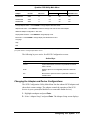
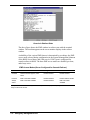
Using the Symbios SCSI Utility................................................................................... 3-16
Running the Symbios SCSI Utility.......................................................................... 3-16
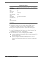
Changing the Adapter and Device Configurations................................................... 3-17
Using the Optional RAID Controller............................................................................ 3-20
Factory Installed Controller .................................................................................... 3-20
Add-on Controller .................................................................................................. 3-20
DACCF Configuration Utility................................................................................. 3-21
Configuring System Board Jumpers............................................................................. 3-22
Moving System Board Jumpers .............................................................................. 3-23
Resetting the CMOS NVRAM................................................................................ 3-24
Clearing and Changing Passwords .......................................................................... 3-24
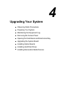
Upgrading Your System .....................................................4-1
Observing Static Precautions ......................................................................................... 4-2
Preparing Your System for Upgrade .............................................................................. 4-3
Preparing the Equipment Log ........................................................................................ 4-3
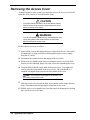
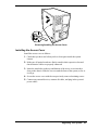
Removing the Access Cover .......................................................................................... 4-4
Installing the Access Cover....................................................................................... 4-5
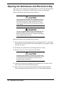
Opening the Subchassis and Electronics Bay.................................................................. 4-6
Closing the Subchassis and Electronics Bay.............................................................. 4-7
Upgrading the System Board ......................................................................................... 4-8
Replacing the Real-time Clock Battery ..................................................................... 4-8
Installing/Removing the Processor Cartridge........................................................... 4-10
Installing DIMM Modules ...................................................................................... 4-14
Installing Option Boards.............................................................................................. 4-19
Installation Considerations...................................................................................... 4-20
Controller/Adapter Hardware Configurations.......................................................... 4-21
Installing an Option Board...................................................................................... 4-21
Removing an Option Board .................................................................................... 4-22
Installing Hard Disk Drives ......................................................................................... 4-24
Installing an Optional SCSI Hard Disk Drive.......................................................... 4-25
Hot-Swapping a SCSI Hard Disk Drive .................................................................. 4-26
Installing Removable Media Devices ........................................................................... 4-27
Installing a 5 1/4-Inch Media Device ...................................................................... 4-28
Removing a 5 1/4-Inch Media Device..................................................................... 4-30
Solving Problems................................................................5-1
Static Precautions .......................................................................................................... 5-2
Troubleshooting Checklists............................................................................................ 5-2
Initial System Startup ............................................................................................... 5-3
Running New Application Software.......................................................................... 5-4
After System Has Been Running Correctly ............................................................... 5-4
iv Contents
Additional Troubleshooting Procedures ......................................................................... 5-5
Preparing the System for Diagnostic Testing............................................................. 5-5
Monitoring POST ..................................................................................................... 5-6
Verifying Proper Operation of Key System Indicators............................................... 5-7
Confirming Loading of the Operating System........................................................... 5-7
Specific Problems and Corrective Actions ..................................................................... 5-7
Power LED Does Not Light...................................................................................... 5-8
No Beep Code .......................................................................................................... 5-8
No Characters Appear on Screen .............................................................................. 5-8
Characters are Distorted or Incorrect......................................................................... 5-9
System Cooling Fan(s) Does Not Rotate................................................................... 5-9
Diskette Drive Activity LED Does Not Light.......................................................... 5-10
Hard Disk Drive Activity LED Does Not Light....................................................... 5-10
CD ROM Drive Activity Light Does Not Light....................................................... 5-11
Problems with Application Software....................................................................... 5-11
Press F2 Key to Enter Setup: Prompt Does Not Display.......................................... 5-11
Bootable CD-ROM Is Not Detected........................................................................ 5-13
Problems with the Network..................................................................................... 5-14
PCI Installation Tips.................................................................................................... 5-14
BIOS User’s Information............................................................................................. 5-15
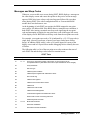
Error and Status Messages ...................................................................................... 5-15
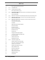
Messages and Beep Codes ...................................................................................... 5-17
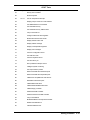
POST Error Codes and Messages............................................................................ 5-21
System Cabling ..................................................................A-1
Before You Begin..........................................................................................................A-2
Static Precautions ..........................................................................................................A-2
Standard Configuration..................................................................................................A-2
Power Cabling..........................................................................................................A-3
Diskette Drive Data Cabling .....................................................................................A-3
SCSI Cabling............................................................................................................A-3
RAID Configuration......................................................................................................A-5
System Setup Utility...........................................................B-1
Creating SSU Diskettes .................................................................................................B-3
Running the SSU...........................................................................................................B-3
Customizing the SSU................................................................................................B-4
Launching a Task .....................................................................................................B-5
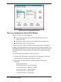
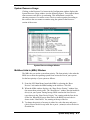
Resource Configuration Add-in (RCA) Window.......................................................B-6
Defining an ISA Board .............................................................................................B-7
Adding and Removing ISA Boards ...........................................................................B-8
Modifying Resources................................................................................................B-8
Recommended Resource Settings .............................................................................B-9
System Resource Usage..........................................................................................B-11
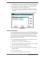
Multiboot Add-in (MBA) Window .........................................................................B-11
Password Administration (PWA) Window..............................................................B-12
System Event Log (SEL) Window ..........................................................................B-12
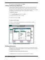
Sensor Data Record (SDR) Manager Add-In Window.............................................B-13
Field Replaceable Unit (FRU) Manager Add-In Window ........................................B-14
Exiting the SSU...........................................................................................................B-14
Contents
v
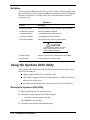
Emergency Management Port........................................... C-1
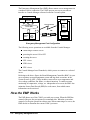
How the EMP Works.....................................................................................................C-2
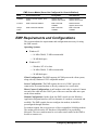
EMP Requirements and Configurations .........................................................................C-5
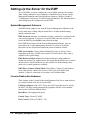
Setting Up the Server for the EMP.................................................................................C-6
System Management Submenu .................................................................................C-6
Console Redirection Submenu ..................................................................................C-6
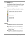
Main EMP Window.......................................................................................................C-7
Toolbar ....................................................................................................................C-7
Status Bar.................................................................................................................C-7
EMP Console Main Menu ........................................................................................C-8
Server Control Operations ........................................................................................C-8
Phonebook...................................................................................................................C-12
Management Plug-ins ..................................................................................................C-13
SEL Viewer............................................................................................................C-13
SDR Viewer ...........................................................................................................C-14
FRU Viewer ...........................................................................................................C-15
FRU and SDR Load Utility..........................................................................................C-16
When to Run the FRUSDR Load Utility .................................................................C-16
What You Need to Do ............................................................................................C-17
How You Use the FRUSDR Load Utility................................................................C-17
Cleaning Up and Exiting.........................................................................................C-21
Glossary
Equipment Log
vi Contents
1
System Overview
System Chassis Features
System Board Features
System Security Features
The MH4500 System is a modular, multiprocessing server based on the
Intel Pentium® II Xeon™ microprocessor. The combination of compute
performance, memory capacity, and integrated input/output (I/O) provides a
high performance environment for many server market applications. These
range from large corporations supporting remote offices to small companies
looking to obtain basic connectivity capability such as file and print services,
email, web access, and web site server.
As application requirements increase, you can expand your server with
additional processors, memory, add-in boards, and peripheral devices (such as
tape devices and hard disk drives).
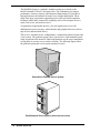
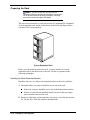
The server is available in two configurations: a stand-alone pedestal system and
a rack system. The pedestal system can be converted to a rack-mounted system
using an optional rack mount kit. Both configurations use the same components
(except there is no outer covers on the rack unit). The following figures show
the pedestal system and a rack system mounted in a rack.
Stand-Alone Pedestal Server System
Rack Mounted Server System (three servers shown)
1-2 System Overview
Your server features the following major components:
up to four high-performance Pentium II Xeon processors, each packaged
in a Single Edge Connector (S.E.C.) cartridge
integrated 512 KB or 1 MB secondary cache integrated in the S.E.C.
cartridge
128 MB to 4 GB of memory, using up to sixteen dual-inline memory
modules (DIMMs)
six PCI expansion slots for add-in boards (one slot shared with an ISA
slot; one slot for half-length PCI boards).
one half-length ISA expansion slot for add-in boards (shared with a PCI
slot)
onboard Cirrus Logic CL-GD5480 Super Video Graphics Array (SVGA)
controller
2 MB of video DRAM memory
onboard single channel enhanced IDE controller
onboard Symbios SYM53C810AE single channel narrow SCSI controller
on the PCI-A bus providing a narrow SCSI interface for 5 1/4-inch
devices
onboard Symbios SYM53C896 dual-channel wide SCSI controller on the
PCI-B bus providing an ultra 2 wide SCSI interface for 3 1/2-inch
devices
1.44MB diskette drive
three 5 1/4-inch bays for removable media devices
SCSI CD-ROM drive
six SCSI hot swap hard disk drive expansion bays
SCSI single connector attachment (SCA) compatible backplane that
provides continuous fast/wide ultra 2 SCSI bus for access to all hot-swap
drive bays
PS/2-compatible mouse and keyboard ports
VGA video port
one Universal Serial Bus (USB) port.
System Chassis Features
The system chassis is an easy-to-expand, fabricated metal structure housing the
power supplies, fans, expansion bays, system board, and supporting
components. A key feature of the chassis is the “swing-out” electronics bay and
subchassis modules, allowing easy access to the interior of the system.
System Overview 1-3
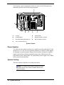
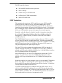
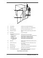
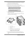
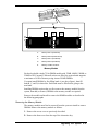
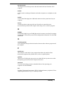
Several major system component locations are shown in the following figure
and briefly described in the following paragraphs.
G
F
A
B
C
D
E
A.
Fans (8)
E.
System Board
B.
SCSI Backplane
F.
Expansion Board Connectors
C.
Removable Media Device Bays (3)
G.
Memory Module Connector
D.
S.E.C. Processor Bays (4)
System Chassis
Power Supplies
Two 400 watt auto-voltage-sensing power supplies provide system power. Each
operates at 115 or 230 Vac at an operating frequency of 50/60 Hz. Both supplies
are designed to operate together during system operation. Both power supplies
comply with existing emissions standards and provide sufficient power for a
fully loaded system configuration. An optional third power supply can be added
to the system as a backup unit.
System Cooling
The chassis houses eight fans for cooling and airflow.
Note: To maintain proper system cooling and air flow,
the chassis access cover must be installed whenever the
system is running.
1-4 System Overview
Peripheral Bays
The system supports a variety of standard PC AT-compatible peripheral devices.
The chassis includes the following peripheral bays:
3 1/2-inch front panel bay for mounting the standard 3 1/2-inch diskette
drive (supports 720 KB and 1.44 MB diskettes)
three 5 /14-inch removable media device front panel bays for mounting
one inch high 5 1/4-inch peripheral devices, including the standard SCSI
CD ROM drive.
Note: Mounting a hard drive in the 5 1/4-inch bay is not
recommended due to cooling restraints and EMI
requirements.
six internal hard disk drive bays for mounting up to six, one inch high,
SCSI hot-swap hard disk drives.
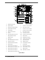
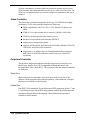
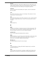
System Board Features
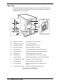
The system board features processor and memory subsystems residing on the
board. The following figure shows the components on the system board. Brief
descriptions of the major components follow the figure.
System Overview 1-5
A
B CD E
F
G
MM
LL
KK
JJ
II
HH
GG
FF
EE
DD
CC
BB
AA
Z
Y
H
I
P
Q
L
R
X
W
V
S
M
T
N
O
U
A.
Wide SCSI B Connector
U.
VRM Connector for Processor 1
B.
System Jumpers
V.
Processor 1, Slot 2 Connector
C.
Hard Drive Input LED Connector
W.
Main Power Connector
D.
System Speaker Connector
X.
Processor 2, Slot 2 Connector
E.
Lithium Battery
Y.
Processor 3, Slot 2 Connector
F.
Wake-on LAN Connector
Z.
Main Power Connector
G.
ISA Slot
AA.
Front Panel Connector
H.
PCI Slots B4, B3, B2, B1, A3, A2
BB.
Processor 4, Slot 2 Connector
I.
Memory Module Connector
CC.
IDE Connector
J.
ICMB Connector
DD.
Diskette Drive Connector
K.
PCI Slot A1
EE.
Auxiliary Power Connector
L.
Video and Parallel Port Connectors
FF.
USB Internal Header
M.
Serial Port Connector
GG.
SMBus Connector
N.
Keyboard and Mouse Connector
HH.
F16 Expansion Connector
O.
USB Connector
II.
ITP Connector
P.
VRM Connector for Processor 4
JJ.
Narrow SCSI Connector
Q.
VRM Connector for Processors 4 and 3
KK.
External IPMB Connector
R.
VRM Connector for Processor 3
LL
SMM Connector
S.
VRM Connector for Processor 2
MM.
Wide SCSI A Connector
T.
VRM Connector for Processors 2 and 1
System Board
1-6 System Overview
J
K
Pentium II Xeon Processor
The system board supports up to four Pentium II Xeon processors, each
packaged in a Single Edge Contact (S.E.C.) cartridge. The cartridge includes the
processor core with an integrated 16 KB primary (L1) cache; the secondary (L2)
cache; a thermal plate; and a back cover. The processor implements the MMX™
technology and the processor’s numeric coprocessor significantly increases the
speed of floating-point operations.
The processor external interface operates at 100 MHz. The second-level cache is
located on the substrate of the S.E.C. cartridge. The cache includes burst
pipelined synchronous static RAM (BSRAM). The L2 cache is offered in 512
KB and 1 MB configurations, with error correcting code (ECC) that operates at
half the core clock rate.
The processors are supported by one or more voltage regulator modules (VRM)
on the system board, with the number of VRMs dependent on the number of
processors installed.
Each S.E.C cartridge connects to the system board through a 330-pin Slot 2
edge connector. The Slot 2 connectors are arranged in a vertical stack of four on
the system board. The VRM modules are located adjacent to the processors.
System Memory
System memory is mounted on a memory module that connects to the system
board. The module contains sixteen 168-pin DIMM sockets arranged in four
banks. Up to 4 GB of EDO DIMM memory is supported, with 32 MB being the
minimum (the system ships with a minimum of 128 MB). The memory module
supports a 64/72 bit four-way-interleaved pathway to main memory on the
module and supports 4:1 interleaving.
System memory begins at address 0 and is continuous (flat addressing) up to the
maximum amount of DRAM installed (exception: system memory is
noncontiguous in the ranges defined as memory holes using configuration
registers). The system supports both base (conventional) and extended memory.
The system BIOS automatically detects, sizes, and initializes the memory array,
depending on the type, size, and speed of the installed DIMMs. The BIOS
reports memory size and allocation to the system via configuration registers.
The memory module connects to the system board through a 242-pin connector.
I/O Expansion Slots
The server's expansion capabilities meet the needs of file and application servers
for high performance I/O by providing a combination of PCI local bus and ISA
connectors.
The system board has one full-length ISA bus connector. The connector shares a
chassis expansion slot with a PCI connector and supports half-length ISA
boards.
System Overview 1-7
ISA features include:
bus speed up to 8.33 MHz
16-bit memory addressing
Type A transfers at 5.33 MB/second
Type B transfers at 8 MB/second
8- or 16-bit data transfers
Plug and Play ready.
The system board has two 32-bit PCI bus segments: PCI-A and PCI-B. The
segments provide seven PCI connectors, three on PCI-A and four on PCI-B.
PCI-A supports half-length boards only and PCI-B supports full-length boards.
One of the PCI-B connectors shares a chassis expansion slot with an ISA
connector.
PCI features include:
bus speed up to 33 MHz
32-bit memory addressing
5 V signaling environment
burst transfers of up to 133 Mbps
8-, 16-, or 32-bit data transfers
Plug and Play ready
parity enabled.
Real-Time Clock/Calendar
The real-time clock provides system clock/calendar information stored in a nonvolatile memory (NVRAM). The replaceable real-time clock battery provides
power backup for the real-time clock.
BIOS
A BIOS and Setup Utility are located in the Flash EPROM on the system board
and include support for system setup and PCI/ISA Plug-and-Play autoconfiguration. A number of security, reliability, and management features also
have been incorporated to meet vital server needs.
IDE Controller
The system includes a single channel enhanced IDE interface controller. The
controller has a primary connector located on the system board that supports a
master and a slave device.
1-8 System Overview
The IDE controller features:
PIO and IDE DMA/bus master operations
Mode 4 timings
transfer rates up to 22 MB/second
buffering for PCI/IDE burst transfers
master/slave IDE mode.
SCSI Controllers
The system board contains two SCSI controllers: a narrow SCSI controller
(SYM53C810AE) on the PCI-A bus, and a dual-channel wide LVD/SE
(Ultra2/Ultra) SCSI controller (SYM53C896) on the PCI-B bus. The narrow
controller provides support for legacy 8-bit SCSI devices in the 5 1/4-inch drive
bays, including the factory installed SCSI CD-ROM drive. The wide controller
drives one SCSI backplane and provides support for external expansion.
Internally, each wide channel is identical, capable of operations using either
8- or 16-bit SCSI providing 10 MB/sec (Fast-10) or 20 MB/sec (Fast-20)
throughput, or 20 MB/sec (Ultra), 40 MB/sec (Ultra-wide) or 80 MB/sec
(40 MHz) (Ultra-2).
The SYM53C810AE (narrow) contains a high-performance SCSI core capable
of Fast 8-bit SCSI transfers in single-ended mode. It provides programmable
active negation, PCI zero wait-state bursts of faster than 110 MB/sec at 33 MHz,
and SCSI transfer rates from 5 to 10 MB/sec. The narrow SCSI comes in a
100-pin rectangular plastic quad flat pack (PQFP).
The Sym53C896 (wide) contains a high-performance SCSI bus interface. It
supports SE mode with 8-bit (10 or 20 MB/sec) or 16-bit (20 or 40 MB/sec)
transfers and LVD mode with 8-bit (40 MB/sec) or 16-bit (80 MB/sec) transfers
in a 329-pin ball grid array (BGA) package.
Each controller has its own set of PCI configuration registers and SCSI I/O
registers. As a PCI 2.1 bus master, the SYM53C896 supports burst data
transfers on PCI up to the maximum rate of 132 MB/second using on-chip
buffers.
In the hot-swap bay, the system supports up to six, one-inch high SCSI hard disk
drives. Also, in the 5 1/4-inch bays, the system supports three SCSI or IDE
devices (the SCSI controller itself supports more devices, but the 5 1/4-inch bay
can only hold a maximum of three devices).
A wide SCSI cable provides two connectors for Ultra SCSI devices, one of
which is used for the SCSI backplane. However, SCSI devices do not need to
operate at the ultra transfer rate. All drives on the bus must be Ultra-2 (LVD) to
run at 80 MB/sec (40 MHz). The 5, 10, and 20 MHz operations can coexist on
the bus and each device interacts at its appropriate speed.
System Overview 1-9
No logic, termination, or resistor loads are required to connect devices to the
SCSI controller other than termination in the device at the end of the cable. The
SCSI bus is terminated on the system board with active terminators that can be
disabled.
Video Controller
The system has an onboard integrated Cirrus Logic CL-GD5480 64-bit highperformance SVGA subsystem that supports the following:
BIOS compatibility with VGA, EGA, CGA, Hercules Graphics, and
MDA
2 MB of 10 ns video random access memory (VRAM) video buffer
16-bit bus for high-speed display memory access
hardware accelerated bit block transfers (BITBLT)
display power management system
supports 100 Hz refresh, non-interlaced at 640x480, 800x600, 1024x768,
1240x1024, and 1600x1200 resolutions
displays up to 16 million colors at 640x480 and 800x600 resolutions,
64K colors at 1024x768 resolutions, and 256 colors at 1280x1024
resolutions.
Peripheral Controller
The advanced integrated peripheral controller supports two serial ports, one
parallel port, diskette drive, PS/2-compatible keyboard and mouse, and
integrated Real Time Clock (RTC). The system provides the connector interface
for each port.
Serial Ports
Both serial ports are relocatable. Each serial port can be set to one of four
different COM ports and can be enabled separately. When disabled, serial port
interrupts are available to add-in boards.
Parallel Port
One IEEE 1284-compatible 25-pin bidirectional EPP (supporting levels 1.7 and
1.9) parallel port is provided. BIOS programming enables the parallel port and
determines the port address and interrupt. When disabled, the interrupt is
available to add-in boards.
1-10 System Overview
External Device Connectors
The external I/O connectors provide support for a PS/2 compatible mouse and a
keyboard, connector for VGA monitor, two serial port connectors, a parallel port
connector, and a USB connector.
System Board Management Controller (BMC)
Server management is controlled by the System Board Management Controller
(BMC). The BMC and associated circuits are powered from a 5Vdc standby
voltage, which remains active when system power is switched off.
The BMC supports the Emergency Management Port (EMP) Console which
allows remote server management via a modem or direct connection to a
manager system. Events monitored by the manager system include overtemperature and over-voltage conditions, fan failure, or chassis intrusion.
Information on the Emergency Management Port (EMP) Console is included in
Appendix C, “Emergency Management Port.”
System Security Features
To help prevent unauthorized entry or use of the system, the system includes a
three-position key lock/switch combination to permit selected access to the drive
bays. The system also includes Server Management software that monitors the
chassis intrusion microswitch.
Mechanical Locks and Monitoring
The chassis intrusion microswitch is activated whenever the system’s access
cover is removed (pedestal system only). When the access cover is removed, the
switch transmits an alarm signal to the system board, where server management
software processes the signal. The alarm system software can be programmed to
respond to an intrusion by powering down the system or by locking the
keyboard.
Software Locks
The BIOS Setup Utility and the System Setup Utility (SSU) provide a number
of security features to prevent unauthorized or accidental access to the system.
Once the security measures are enabled, access to the system is allowed only
after the user enters the correct password(s). For example, the SSU allows you
to:
enable the keyboard lockout timer so that the server requires a password
to reactivate the keyboard and mouse after a specified time-out period
(1 to 120 minutes)
set and enable administrator and user passwords
set secure mode to prevent keyboard or mouse input and to prevent use of
the front panel reset and power switches
System Overview 1-11
activate a hot-key combination to enter secure mode quickly
disable writing to the diskette drive when secure mode is set.
Further information on the security features is contained in
Chapter 3, “Configuring Your System.”
1-12 System Overview
2
Setting Up Your System
Selecting a Site
Unpacking the System
Getting Familiar with the System
Installing the System
Connecting Peripherals
Connecting the Power Cords
Powering on the System
Converting to a Rack Mount Server Unit
Your system ships as a stand-alone, single server pedestal unit or as a rack unit
ready to install in a rack. The pedestal system can also be converted to a rackmounted server unit using a rack conversion kit (not supplied). You can
purchase the kit from your dealer.
The information in this chapter pertains to both configurations. Where
differences occur between configurations, they are noted.
Use this chapter to guide you in
selecting a site
unpacking the system
becoming familiar with the system
installing the system
connecting peripherals
connecting power cords
powering on the system
converting the system to a rack-mounted server unit.
Selecting a Site
The system operates reliably in a typical office environment. Choose a site that
meets the following requirements.
Install the system near two or more grounded, three-pronged power
outlets, preferably on separate electrical circuits.
Note: For the United States and Canada, this means
NEMA 5-15R outlets for 100-120 Vac or NEMA 6-15R
outlets for 200-240 Vac. For other international sites, this
means three-pronged power outlets applicable for the
electrical code of the region.
! WARNING
Be sure the power service connection is through a properly
grounded outlet.
The site must be clean, dust-free, and well ventilated. Keep the front and
rear ventilation openings free of obstructions and away from sources of
heat, vibration, or physical shock.
2-2 Setting Up Your System
The site must be isolated from strong electromagnetic fields and electrical
noise produced by electrical devices such as air conditioners, large fans,
large electric motors, radio and TV transmitters, and high-frequency
security devices.
Provide at least eight inches (20.32 centimeters) behind the system and
three inches (eight centimeters) on each side of the system for proper
cooling, airflow, and cable clearance.
Site the system so that it is easily accessible for system maintenance and
installation of system upgrades.
With the site selected, unpack and set up the system as described next.
Unpacking the System
! WARNING
Your system weighs approximately 85 pounds (38.25 kg),
minimum configuration. If your system contains optional
boards and peripheral devices, it may weigh up to 100
pounds (45.4 kg). To avoid personal injury, make sure you
have someone help you lift or move the system.
When you receive your system, inspect the shipping carton(s) prior to
unpacking. If the shipping carton(s) is damaged, note the damage, and if
possible, photograph it for reference.
After removing the contents of the carton(s), inspect for damage. If the contents
appear damaged, file a damage claim with the carrier immediately. Keep the
cartons and the packing materials.
Check that you have all the parts listed on the packing slip. If any are missing,
contact the dealer where you purchased the system.
Set the system where you can easily look at the front and rear. Take a few
minutes and become familiar with the system’s controls, indicators, and
connectors (see “Getting Familiar with the System,” next).
Setting Up Your System 2-3
Getting Familiar with the System
Before setting up your system, you should become familiar with the system’s
features, such as the location of your system's front and rear panel switches,
indicators, and connectors.
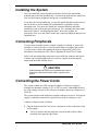
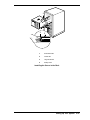
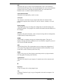
Front View
The following figure shows locations of controls and indicators on the front of
the system. A brief description of the controls and indicators follows the figure.
Note: The stand-alone server unit and its controls and
indicators are shown in the following front and rear view
figures. All controls and indicators shown on the stand-alone
unit are the same on the rack unit except for orientation, as
the unit is mounted in the rack on its side.
2-4 Setting Up Your System
A
BC
D
E
F
G
L
H
I
J
K
A.
CD-ROM Drive
Standard, factory-installed CD-ROM Drive
B.
Diskette Drive
Standard, factory-installed 3 1/2-inch diskette drive.
C.
Power On/Off Button
Press to turn system DC power on or off.
D.
Sleep/Service Button
Press to put system in power saving mode or service
mode.
E.
Reset Button
Press to reset system.
F.
Front Panel LEDs (starting at top)
Power On
Disk Bay Power On
Hard Disk Activity
Fan Failure
Power Supply Failure
Six Hard Drive LEDs
(labeled 0 - 5)
When lit (green), DC power is present.
When lit (green), DC power is present at hard drive bay.
When lit (green), hard disk drive is in use.
When lit (yellow), a cooling fan has failed.
When lit (yellow), a power supply has failed.
When lit (yellow), associated drive failed.
G.
NMI Button
Used for system troubleshooting by qualified technical
personnel only.
H.
System Security Lock
Key operated lock to prevent unauthorized access to
server controls.
I.
EMI Shield Lock
Latches metal EMI shield door.
J.
Internal Drive Bays
Holds up to six 1” high SCSI hot-swap hard disk drives.
K.
Metal EMI Shield
EMI shield for SCSI hard drives.
L.
5 1/4-inch Expansion Drive Bay
Holds up to three 5 1/4-inch devices, including the
factory-installed CD-ROM drive.
Front Features and Controls
Setting Up Your System 2-5
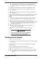
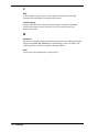
Rear View
The following figure shows the location of system controls, indicators, and
connectors on the rear of the system. The rack unit is similar except that it is
mounted in the rack on its side.
H
A
B
C
D
E
F
L
M
I
J
K
G
A.
Parallel Port Connector
25-pin parallel printer port connector.
B.
VGA Monitor Connector
15-pin monitor connector.
C.
Serial Port A (COM1)
9-pin serial COM1 port connector.
D.
Serial Port B (COM2)
9-pin serial COM2 port connector.
E.
Mouse Connector
6-pin PS/2-compatible mini-DIN mouse connector.
F.
Keyboard Connector
6-pin PS/2-compatible mini-DIN keyboard connector.
G.
USB Connector
Single Universal Serial Bus connector.
H.
Expansion Slots
1 shared ISA/PCI slot, 1 ISA slot, and 6 PCI slots.
I.
Power Supply Bay
Optional power supply bay for one backup power supply.
J.
AC Input Power Connector
Supplies AC power to the power supply.
K.
Power Supply Fan
Supplies cooling air to the power supply.
L.
Power Supply LED
When lit, indicates AC power is available to power
supply.
M.
Power Supply Failure LED
When not lit, indicates power supply failure.
Rear Features and Controls
2-6 Setting Up Your System
Installing the System
How you install the system depends on whether you have the stand-alone
pedestal unit or the rack-mounted unit. If you have the pedestal unit, install it at
your site and connect peripherals and power as explained next.
If you have the rack mounted unit, you need to install slide bars on the sides of
the unit before it can be installed in a standard EIA-compatible 19-inch
equipment rack. You must also install rack extension brackets and slider
assemblies in the rack for the unit to mount on. See “Attaching the Outer Slide
Bars to the Chassis” and Preparing the Rack” later in this chapter for
procedures. Once your rack unit is in the rack, connect peripherals and power as
explained next.
Connecting Peripherals
If your system normally operates without a monitor, keyboard, or mouse (for
example, as a network server), you must install them to configure the system.
You may remove them after running the System Setup Utility (SSU). For
information on running the SSU, refer to Appendix B of this User’s Guide.
Refer to the preceding figure and connect your keyboard, monitor, and mouse.
Connect any external peripheral devices such as a printer by following the
instructions included with the device.
! CAUTION
System damage may result if the keyboard/mouse cable is
connected or disconnected when power is applied to the
system.
Connecting the Power Cords
The system contains two 400-watt power supplies. Each power supply is
designed for automatic sensing of 115 or 230 Vac power, eliminating the need
for a line voltage selector switch. The power supplies operate at a frequency of
50/60 Hz.
The system operates with both power supplies connected to power. Each power
supply is separately connected to a power source with its own power cord.
Connect each power cord as follows.
1. Plug the female end of the AC power cord into its socket on the back of the
power supply.
You may need to slide the plug-lock away from the socket to allow
insertion of the plug into the socket.
Setting Up Your System 2-7
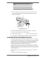
To unplug the power cord, slide the lock away from the plug while
carefully pulling it out of the socket. Do not pull on the cord, only the
plug.
2. Plug the male end of the power cord into a wall-mounted power outlet.
Plug the male end of the power cord into an NEMA 5-15R outlet for
100-120 Vac.
Plug the male end of the power cord into an NEMA 6-15R outlet for
200-240 Vac.
If the power cords supplied with the system are not compatible with the AC wall
outlets in your region, obtain suitable power cords that meet the following
criteria.
The power cord must be rated for the available AC voltage and have a
current rating that is at least 125% of the current rating of the system.
The power cord connector that plugs into the wall outlet must be
terminated in a grounding-type male plug designed for use in your region.
It must have certification marks showing certification by an agency
acceptable in your region.
The power cord connector that plugs into the system must be an
IEC type CEE-22 female connector.
The power cord must be less than 1.8 meters (6.0 feet) long.
! WARNING
Your system ships with two power cords, one for each power
supply. Do not attempt to modify or use the supplied AC
power cords if they are not the exact type required.
Powering On the System
Power on your system as follows.
1. Make sure all external devices (monitor, keyboard, mouse) and power cords
are connected.
2. Make sure both AC power supply cords are connected to the system and
power outlets.
3. Power on the monitor and any other external devices.
4. Press the dc push-button power on/off switch on the front panel.
Verify that the dc power-on LED on the front panel is lit. If it is not lit,
ensure that the AC power cords are connected to functional AC power
sources.
2-8 Setting Up Your System
Verify that the AC power-on and power supply failure LEDs on the
back of each power supply are lit. If the power supply failure LED is not
lit, ensure that the AC power cord is connected to a functional AC
power source.
! WARNING
The DC push-button on/off switch on the front panel does
not turn off AC power. To turn off AC power, you must
unplug all power supply cords from either the power supplies
or from the power sources. Do NOT turn off AC power
without first turning off DC power.
After a few seconds your system begins the internal Power-On Self Tests
(POST). POST automatically checks the system board, CPU module(s),
memory, keyboard, and most installed peripheral devices.
! CAUTION
Always allow POST to complete before powering down your
system.
! CAUTION
The server management logic on your system board
monitors and logs system voltage changes. When powering
down your system, you may experience up to five seconds
delay from the time you press the push-button power on/off
switch on the front panel and your system powering down.
This is normal system operation and is required by the
server management logic.
If you have problems powering on your system, refer to Chapter 5, “Solving
Problems,” in this guide.
After you have successfully powered on your system, insert the
EXPRESSBUILDER CD ROM into the CD ROM drive, reboot the system, and
follow the screen prompts to run EXPRESSBUILDER.
Setting Up Your System 2-9
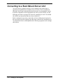
Converting to a Rack Mount Server Unit
You can convert a pedestal system to a rack mounted server unit using an
optional rack installation kit available from your dealer. The kit contains the
slide rails, bezel frame, and other hardware necessary for mounting the system
in an EIA-compatible 19-inch equipment rack. Once you have the kit, use the
following procedures to prepare the system for mounting in a rack. You should
also follow any instructions that may come with the kit.
Before starting the conversion, ensure that you have all the parts necessary for
the conversion (check the packing slip that comes with the rack installation kit).
You should also observe and implement the following equipment rack warnings
and cautions.
2-10 Setting Up Your System
Equipment Rack Warnings and Cautions
Observe and implement the following equipment rack warnings and cautions
before starting the conversion.
! WARNING
Anchor the Equipment Rack. The equipment rack must be
anchored to an unmovable support to prevent it from falling
over when one or more servers are extended in front of it on
slide assemblies. The anchors must be able to withstand a
force of up to 113 kg (250 lbs). You must also consider the
weight of any other device installed in the rack.
Main AC Power Disconnect. You are responsible for
installing an AC power disconnect for the entire rack unit.
This main disconnect must be readily accessible, and it must
be labeled as controlling power to the entire unit, not just to
the server(s).
Grounding the Rack Installation. To avoid a potential
electrical shock hazard, you must include a third wire safety
grounding conductor with the rack installation. If server
power cords are plugged into AC outlets that are part of the
rack, then you must provide proper grounding for the rack
itself. If server power cords are plugged into wall AC outlets,
the safety grounding conductor in each power cord provides
proper grounding only for the server. You must provide
additional, proper grounding for the rack and other devices
installed in it.
Overcurrent Protection. The server is designed for an AC
line voltage source with up to 20 amperes of overcurrent
protection. If the power system for the equipment rack is
installed on a branch circuit with more than 20 amperes of
protection, you must provide supplemental protection for the
server. If more than one server is installed in the rack, the
power source for each server must be from a separate
branch circuit. The overall current rating of a server
configured with three power supplies is under 12 amperes.
! CAUTION
Temperature. The operating temperature of the server,
when installed in an equipment rack, must not go below 5 °C
(41 °F) or rise above 35 °C (95 °F). Extreme fluctuations in
temperature can cause a variety of problems in your server.
Ventilation. The equipment rack must provide sufficient
airflow to the front of the server to maintain proper cooling. It
must also include ventilation sufficient to exhaust a
maximum of 4,100 Btu's per hour for the server. The rack
selected and the ventilation provided must be suitable to the
environment in which the server is used.
Setting Up Your System 2-11
Converting the System Pedestal Unit
Converting your pedestal system to a rack mounted unit consists of:
removing the top and side covers
removing the bezel frame
installing a new bezel frame
installing handles
attaching slide rails to the chassis
preparing the rack.
After the system unit is converted to a rack unit, install the unit in the rack (see
“Installing the Unit in the Rack” later in this chapter).
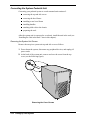
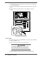
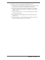
Removing the System Unit Covers
Remove the one piece system unit top and side cover as follows.
1. Power down the system, disconnect any peripheral devices, and unplug all
power cords.
2. At the back of the system unit, remove and save the screw from the top
cover (see the following figure).
Removing the Cover Screws
2-12 Setting Up Your System
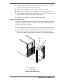
3. Grasp the built-in handle on the back of the cover and, using an even pull,
slide the cover back about an inch until it stops.
4. Pull the cover straight up and off the chassis. Set the cover aside.
5. Remove and save the two screws holding the access (side) panel in place.
6. Grasp the built-in handle on the back of the access panel and, using an even
pull, slide the cover back about an inch until it stops.
7. Pull the cover straight away from the chassis and set aside.
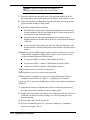
Replacing the Bezel Frame
The bezel frame must be replaced with a new bezel frame containing cutouts for
two chassis handles. Remove the bezel frame from the system unit and replace it
with a new bezel frame as follows.
1. Open the bezel door all the way to the left (as you face the unit) and lift the
door up slightly to free it from the bezel frame, then remove from the frame.
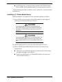
2. Remove the bezel frame by pressing its seven retaining tabs toward the
center of the chassis while pulling the frame away (see the following figure).
B
A
A.
Bezel Frame
B.
Frame Tabs (7)
Replacing the Bezel Frame
Setting Up Your System 2-13
3. Install the new bezel frame by inserting the retaining tabs into their
corresponding slots on the chassis.
4. Install the bezel door by inserting the door onto the hinge pins on the
chassis. Shut the bezel door.
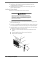
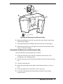
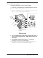
Installing the Chassis Handles
Install the two chassis handles on the chassis as follows.
! WARNING
Attaching the chassis handles requires repositioning the
system unit on its side. The unit weighs between 85 pounds
(38 kg) and 100 pounds (45 kg), depending on configuration.
To avoid injury, make sure you have someone help you to
position the unit on its side.
1. Turn the system unit on its side, with the electronics bay facing up and the
front of the unit facing you.
2. Locate the two rectangular cutouts in the bezel frame, one on each side, and
the two threaded holes in each side of the chassis (see the following figure).
3. Attach the handles, one to a side, to the chassis. Because of the bezel frame
configuration, the handles can only fit one way.
Align the two holes in the handle with the two threaded holes in the
chassis.
Fasten the handle in place with two screws from the kit.
Repeat for the second handle.
A
B
C
D
2-14 Setting Up Your System
A.
Bezel Frame
B.
Rectangular Cutout
C.
Chassis Handle
D.
Screws
Attaching the Chassis Handles
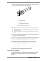
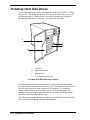
Attaching the Outer Slide Bars to the Chassis
Note: If you have a rack unit, you must use the
following procedure to attach the slide bars before mounting
the unit in the rack. Observe all safety precautions,
warnings, and cautions noted throughout this chapter.
Each slide assembly consists of a large outer bar, a center bar, and a small outer
bar. The large outer bar and the center bar attach to the rack unit. The small
outer bar attaches to the system chassis. As the slide assembly ships as an
assembled unit, you must remove the small outer bar from the assembly before
attaching to the chassis.
Remove the small outer bar from each slide assembly and attach each bar to the
chassis as follows.
1. Position the slide assembly on a flat surface with the small outer bar down.
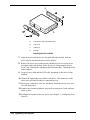
2. Fully extend the three telescoping bars until they lock in place (see the
following figure).
Setting Up Your System 2-15
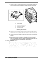
3. While pressing down on the small outer bar safety latch (4 on the following
figure), pull the small outer bar out of the assembly and set aside for
installation on the chassis.
Release the safety latch on the center bar (5 on the figure) and collapse
the large outer bar and center bar together.
Set the assembly aside for later installation in the rack.
4
5
1
2
1.
Large Outer Bar
2.
Center Bar
3.
Small Outer Bar
4.
Safety Latch on Small Outer Bar
5.
Safety Latch on Center Bar
Releasing the Small Outer Bar
2-16 Setting Up Your System
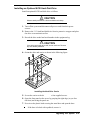
3
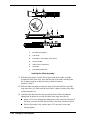
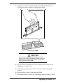
4. Attach each small outer bar to the chassis as follows.
Align the mounting holes in the bar to the threaded holes in the chassis
(see the following figure). The right angle end of the bar goes toward the
front of the chassis.
Secure the bar to the chassis with four screws from the kit.
1
2
4
3
1.
Threaded Holes in Chassis
2.
Safety Latch
3.
Screw (1 of 4)
4.
Small Outer Bar (right angle end)
Attaching the Small Outer Bar to the Chassis
Setting Up Your System 2-17
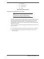
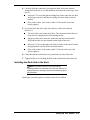
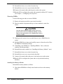
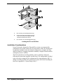
Preparing the Rack
Note: If you have a rack unit, you must use the
following procedure to prepare the rack before mounting the
unit in the rack. Observe all safety precautions, warnings,
and cautions noted throughout this chapter.
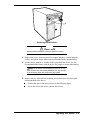
The converted system unit (or rack unit) mounts in a standard EIA-compatible
19-inch equipment rack similar to that shown in the following figure (shown
with three server units installed).
Typical Equipment Rack
Before you can mount the unit in the rack, you must install a set of rack
extension brackets and slider rails to the rack. Do this as explained in the
following paragraphs.
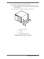
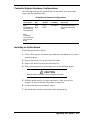
Installing the Rack Extension Brackets
Install the four (two to a side) rack extension brackets on the rack as follows.
1. Determine where you want to install the server unit in the rack.
If the rack is empty, install the server unit in the bottom most position.
If there are units already installed, install your unit in the next empty
space from the bottom of the rack.
2. Remove a right-angle extension bracket, two screws, and a bar nut from the
kit. The bar nut is a flat bar with four threaded holes.
2-18 Setting Up Your System
3. Align the bracket behind the rack’s vertical edge and behind the mounting
holes in the vertical edge (see the following figure).
2
1
4
3
1.
Screw
2.
Rack Vertical Rail
3.
Bar Nut
4.
Right angle Extension Bracket
Installing the Extension Brackets
4. Determine where you want to attach the bracket on the rack’s vertical rail.
When determining where to attach the bracket, be sure to allow space
for additional units.
Mark, with a pencil, the bracket top and bottom hole locations on the
rail.
5. Insert a screw through the marked top hole in the vertical rail and through
the top hole in the extension bracket.
6. Place a bar nut over the screw and loosely thread the screw into the bar nut.
7. Insert a screw through the marked bottom hole in the vertical rail and
extension bracket and loosely thread the screw into the bar nut.
8. Install the remaining three extension brackets, bar nuts, and screws.
Before installing, carefully align each bracket in exactly the same
vertical position as the first bracket.
After installing, check that the brackets are vertically aligned and level
with each other.
9. Tighten all the screws holding the brackets to the rack.
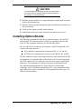
Installing the Slider Assemblies
Use the following procedure to install each slider assembly on the extension
brackets in the rack. Refer to the following figure while performing the
procedure.
Setting Up Your System 2-19
1
2
2
4
5
6
3
2
7
4
2
6
2
1.
Back Extension Bracket
2.
8-32 Screw
3.
Flat Washer, Lock Washer, and 8-32 Nut
4.
Large Outer Bar
5.
Safety Latch on Center Bar
6.
Center Bar
7.
Front Extension Bracket
Installing the Slider Assembly
1. With the safety latch (5 on the above figure) end of the slider assembly
towards the back of the rack, press the flat side of the slider assembly into
the U-shaped sections of the previously installed extension
brackets (1 and 7).
2. Slide the slider assembly towards the front of the rack until the end of the
large outer bar (4) is flush with the end of the U-shaped section of the front
extension bracket (7).
3. Carefully slide the center bar (6) towards the front of the rack until the
oblong hole in the bar is over the first hole in the large outer bar (4).
Insert a 8-32 screw through the oblong hole in the center bar, the hole in
the large outer bar, and into the first hole in the front extension bracket.
Place a flat washer, lock washer, and a 8-32 nut on the screw and
loosely tighten.
2-20 Setting Up Your System
4. Carefully slide the center bar (6) towards the back of the rack until the
oblong hole in the bar is over the third hole from the front of the large outer
bar (4).
Insert an 8-32 screw through the oblong hole in the center bar, the hole
in the large outer bar, and into the oblong slot in the front extension
bracket.
Place a flat washer, lock washer, and a 8-32 nut on the screw and
loosely tighten.
5. Secure the back end of the large outer bar (4) to the back extension
bracket (1).
The end of the outer bar has four holes. The extension bracket has two
holes and two elongated slots for fastening the bar.
Align two holes in the outer bar with a hole and slot in the bracket.
Which holes/slots you use depends on the depth of the rack.
Insert an 8-32 screw through each of the two holes in the outer bar and
through the hole and slot in the extension bracket.
Place a flat washer, lock washer, and a 8-32 nut on each screw and
loosely tighten.
6. Check that the bars and brackets are positioned correctly in the rack.
7. Tighten all the screws holding the bars to the extension brackets and rack.
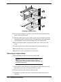
Installing the Rack Unit in the Rack
Note: If you have a rack unit, you must use the
following procedure to install the unit in the rack. Observe all
safety precautions, warnings, and cautions noted throughout
the procedures.
Install your converted unit (or rack unit) in the rack as follows.
Setting Up Your System 2-21
! WARNING
Anchor The Equipment Rack. The equipment rack must be
anchored to an unmovable support to prevent it from falling
over when one or more servers are extended in front of it on
slide assemblies. The anchors must be able to withstand a
force of up to 113 kg (250 lbs). You must also consider the
weight of any other device installed in the rack.
Avoid Injury. The minimum server configuration weighs 38
kg (85 lbs); the maximum configuration weighs 45 kg (100
lbs). To avoid personal injury when installing the server,
have someone help you position the server in the rack.
Do not attempt to lift or move the server unit by the handles
on the power supplies.
1. Pull the telescoping center bar (2 on the following figure) out of each slider
assembly on the rack until it locks in place.
2. With someone helping you, use the handles on the sides of the rack unit to
lift and slide the unit into the slider assemblies.
Align the small bars (1) attached to the sides of the system unit with the
extended center bars (2).
Carefully slide the server unit into the extended center bars until it stops.
Press in on the safety latches (4) on the small bars and carefully slide the
server unit all the way into the rack.
3. Check that the server unit slides in and out of the rack. Grasp the two
handles on the sides of the unit and slowly pull the unit out and push it back
in.
4. Connect all external peripherals and cables.
5. Connect the two power supply cables to the back of the server unit and to a
power source.
6. Power on the server unit.
2-22 Setting Up Your System
2
1 3
4
2
1.
Small Outer Bar
2.
Center Bar
3.
Large Outer Bar
4.
Safety Latch
Installing the Server in the Rack
Setting Up Your System 2-23
3
Configuring Your System
Using the BIOS Setup
Using the Symbios SCSI Utility
Using the Optional RAID Controller
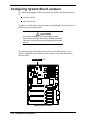
Configuring System Board Jumpers
This chapter describes the Setup utilities that you can use to change your system
configuration. The utilities described in this chapter include:
BIOS Setup Utility
Symbios SCSI Utility.
The BIOS Setup Utility is used to configure the system and any option boards
you may add. The BIOS Setup Utility is stored in the system FLASH memory.
You do not need a diskette to run the BIOS Setup Utility.
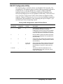
The Symbios SCSI Utility is used to configure the SCSI controller in your
system, perform a SCSI disk format, or verify disk operation on the SCSI disk
drives. The utility is also used to configure any SCSI removable media devices
installed in your system. You do not need a diskette to run this utility as it is
accessible during system boot-up.
In addition, the following utilities are available for your use in configuring the
system. Information on each utility is contained in the referenced appendix.
System Setup Utility (SSU) (see Appendix B, “System Setup Utility”)
Emergency Management Port (EMP) (see Appendix C, “Emergency
Management Port”)
FRUSDR Load Utility (see Appendix C, “Emergency Management
Port”).
The System Setup Utility can be used to configure your system and any option
boards you may add to your system. The SSU reads stored system event
information. Appendix B contains information on the SSU.
The Emergency Management Port (EMP) is used for remote monitoring of the
server. The FRUSDR Load Utility can be used to update the field replacement
unit (FRU), sensor data record (SDR) and desktop management interface (DMI)
flash components. Appendix C contains information on both utilities.
If your system is factory configured, you normally don’t need to run the SSU,
BIOS Setup, or Symbios SCSI Utility unless you want to change the password
or security features, add certain types of option boards or devices, or upgrade
your system board.
Also included in this chapter is information on setting jumpers on the system
board for clearing
CMOS nonvolatile RAM (NVRAM)
System passwords.
3-2 Configuring Your System
Using the BIOS Setup Utility
The BIOS Setup Utility is used to change system configuration parameters. Note
that many BIOS Setup parameters are also configurable with the SSU. However,
BIOS Setup Utility parameters that are settable with the SSU are overwritten by
the SSU the next time the SSU is run. The BIOS Setup Utility is resident in the
system Flash memory and does not require a diskette or an operating system
present to run.
You can access the BIOS Setup utility when you turn on or reboot your system.
Use the following procedure to run the BIOS Setup Utility.
1. Power-on or reboot the system. The “Press <F2> to enter SETUP” message
displays.
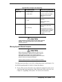
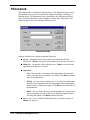
2. Press F2. The BIOS Setup Utility starts and the Main Menu is displayed.
The menu bar at the top of the Main Menu lists the following selections.
Menu Bar Selections
Menu
Use
Main
Use for basic system configuration.
Advanced
Use for setting the Advanced Features available on your system.
Security
Use to set User and Supervisor Passwords and Backup and VirusCheck reminders.
Server
Use for configuring Server Management features.
Boot
Use to configure Boot Device priority.
Exit
Exits current setup.
Use the arrow keys to select a menu or an item on a displayed menu. Press the
value keys (listed in the table below) to cycle through the allowable values for
the selected field. Use the Exit menu’s “Save Changes” selection to save the
current values on all the menus.
To display a submenu, position the cursor on a selection that has a submenu and
press Enter. Selections with submenus are preceded by an arrow.
Refer to the following table for information on the keys you use with BIOS
Setup. These keys are also listed at the bottom of the Setup Menu.
Setup Menu Keys
Key
Function in Setup Menu
F1 or Alt-H
Get Help about an item.
ESC
Exit the current menu and return to the previous menu.
Left or right arrow keys
Move between menus.
Configuring Your System 3-3
Setup Menu Keys
Key
Function in Setup Menu
Up or down arrow keys
Move cursor up and down. The cursor moves only to the
settings that you can change.
-
Select the previous value for the field.
+
Select the next value for the field.
F9
Load default configuration values for this menu.
F10
Save configuration values and exit.
Enter
Execute command or Select submenu.
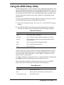
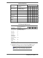
The following BIOS Setup Configuration tables show the default settings for the
BIOS Setup Utility. Recommended values are bold. The tables also provide a
space for you to record any changes you make to these settings.
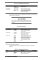
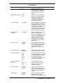
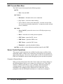
Main Menu
The following table shows the Main Menu settings.
Main Menu
Feature
Choices
Description
System Time
HH:MM:SS
Sets the system time.
System Date
MM/DD/YYYY
Sets the system date.
Legacy Diskette A:
Disabled
360KB
1.2 MB
720KB
1.44 MB
2.88 MB
Selects the diskette type.
Legacy Diskette B:
Disabled
360KB
1.2 MB
720KB
1.44 MB
2.88 MB
Selects the diskette type.
Hard Disk Pre-delay
Disabled
3, 6, 9, 12, 15, 21, or
30 seconds
Adds a delay before the first BIOS
access of a hard drive. Some hard
drives hang if accessed before they
initialize. The delay allows the drive
to initialize after power up, before
being accessed.
Primary IDE Master
Press Enter
Refer to “Primary IDE Master and
Slave Submenu.”
Primary IDE Slave
Press Enter
Refer to “Primary IDE Master and
Slave Submenu.”
Keyboard Features
Press Enter
Refer to “Keyboard Submenu.”
Processor Information
Press Enter
Information for all processors is
3-4 Configuring Your System
Your Setting
Main Menu
Feature
Choices
Description
described.
Your Setting
Language
English (US)
Spanish, Italian
French, German,
Japanese (Kanji)
Selects which language BIOS
displays in.
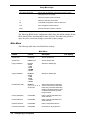
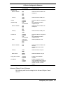
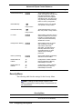
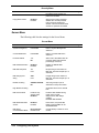
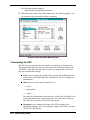
Primary IDE Master and Slave Submenu
The following table shows the settings for the Primary IDE Master and Slave
submenu.
Primary IDE Master and Slave Submenu
Feature
Choices
Description
Type
Auto
Auto allows the system to attempt
auto-detection of the drive type.
None informs the system to ignore
this drive.
Allows the manual entry of some
fields described below.
None
CD-ROM
IDE Removable
ATAPI Removable
Your Setting
User
User allows the manual entry of all
fields described below.
Cylinders
1 to 2048
Number of cylinders on drive. This
field is changeable only for Type
User.
Heads
1 to 64
Number of read/write heads on
drive. This field is changeable only
for Type User.
Sectors
1 to 64
Number of sectors per track. This
field is changeable only for Type
User.
Maximum Capacity
N/A
Computed drive size. This field is
informational only for Type User.
Multi-Sector Transfer
Disabled
2, 4, 8, or 16 sectors
Determines the number of sectors
per block for multi-sector transfers.
This field is informational only for
Type Auto.
LBA Mode Control
Disabled
Enabled
Enabling LBA causes logical block
addressing to be used in place of
cylinders, heads, and sectors. This
field is informational only for Type
Auto.
32 Bit I/O
Disabled
Enabled
Enabling allows 32 bit IDE data
transfers.
Transfer Mode
Standard
Fast PIO 1
Fast PIO 2
Fast PIO 3
Fast PIO 4
Selects the method for moving data
to and from the drive. This field is
informational only for Type Auto.
Configuring Your System 3-5
Primary IDE Master and Slave Submenu
Feature
Choices
Description
Ultra DMA Mode
Disabled
Enabled
Selects the Ultra DMA Mode for
moving data to and from the drive.
Your Setting
Keyboard Submenu
The following table shows the settings for the Keyboard submenu.
Keyboard Submenu
Feature
Choices
Description
NumLock
Auto
On
Off
Selects power-on state for Num
Lock.
Key Click
Disabled
Enabled
Enables or disables key click.
Keyboard auto-repeat
rate
30/sec
26.7/sec
21.8/sec
18.5/sec
13.3/sec
10/sec
6/sec
2/sec
Selects the number of times per
second a key repeats while it is
held down.
Keyboard auto-repeat
delay
1/4 sec
1/2 sec
3/4 sec
1 sec
Selects delay before key repeat.
Your Setting
Advanced Menu
The following table shows the Advanced Menu settings.
Advanced Menu
Feature
Choices
Description
Plug and Play OS
No
Yes
Select Yes if you are booting a
Plug and Play capable operating
system.
Reset Configuration
Data
No
Yes
Select Yes if you want to clear the
system configuration data during
next boot. System automatically
resets to No in next boot.
PCI Configuration
Press Enter
Refer to “PCI Configuration
Submenu.”
I/O Device
Configuration
Press Enter
Refer to “I/O Device Configuration
Submenu.”
3-6 Configuring Your System
Your Setting
Advanced Menu
Feature
Choices
Description
Your Setting
Use Multiprocessor
Specification
1.1
1.4
Selects version of multiprocessor
specification to use. Some
operating systems require version
1.1 for compatibility reasons.
Large Disk Access
Mode
LBA
CHS
Select LBA for IDE drives.
System Wakeup
Feature
Disabled
Enabled
If enabled, the system powers up
upon receiving a “magic packet” on
LAN, ring on COM2, or PME
interrupt from a PCI board.
Pause Before Boot
Enabled
Disabled
Enables five second delay before
booting operating system.
Advanced Chipset
Control
Press Enter
Refer to “Advanced Chipset Control
Submenu.”
PCI Configuration Submenus
The following tables show the settings for the PCI Device Embedded SCSI
submenu and PCI Devices submenu. The submenus should only be changed by
qualified technical personnel.
! CAUTION
Leave the PCI Device Embedded SCSI submenu at factorydefault settings. This submenu should only be changed by
qualified technical personnel.
PCI Device, Embedded SCSI Submenu
Feature
Choices
Description
Your Setting
Option ROM Scan
Enabled
Disabled
Enables option ROM scan of the
selected device. Used to enable
embedded Symbios SCSI
controller
Enable Master
Enabled
Disabled
Enabled selects the device as a
PCI bus master.
Latency Timer
Default
0020h
0040h
0060h
0080h
00A0h
00C0h
00E0h
Minimum guaranteed time, in units
of PCI bus clocks, that a device
may be master on a PCI bus.
Caution: Do not change this setting
unless you fully understand the
priority of this device on the PCI
bus.
Active Termination
Disabled
SCSI A On
Selects the setting of the onboard
Configuring Your System 3-7
PCI Device, Embedded SCSI Submenu
Feature
Choices
SCSI B On
SCSI A & B On
Description
SCSI termination.
Single-Ended
Force/Auto Set
Force A and B
Force B, Auto A
Force A, Auto B
Auto
If set for Force Single, the SCSI
channel defaults to Single-Ended
operation. Auto-Set uses hardware
detection to determine single vs.
double-ended operation.
Your Setting
The PCI Devices submenu (see the following table) should only be changed by
qualified technical personnel.
! CAUTION
Leave the PCI Devices submenu at factory-default settings.
This submenu should only be changed by qualified technical
personnel.
PCI Devices Submenu
Feature
Choices
Description
Option ROM Scan
Enabled
Disabled
Enables option ROM scan of all
devices other than the onboard
SCSI controllers.
Enable Master
Enabled
Disabled
Enabled selects all devices as a
PCI bus master, other than
onboard SCSI controllers.
Latency Timer
Default
0020h
0040h
0060h
0080h
00A0h
00C0h
00E0h
Minimum guaranteed time, in units
of PCI bus clocks, that a device
may be master on a PCI bus.
Caution: Do not change this setting
unless you fully understand the
priority of this device on the PCI
bus.
Your Setting
I/O Device Configuration Submenu
The following table shows the settings for the I/O Device Configuration
submenu.
I/O Device Configuration Submenu
Feature
Choices
Description
COM 1:
Disabled
Enabled
Auto
Auto forces BIOS to configure the
port.
OS Controlled forces OS to
3-8 Configuring Your System
Your Setting
I/O Device Configuration Submenu
Feature
Choices
OS Controlled
Description
configure the port.
Base I/O Address
3F8
2F8
3E8
2E8
Selects the base I/O address for
COM port 1.
Interrupt
IRQ 3
IRQ 4
Selects the IRQ for COM port 1.
Disabled
Enabled
Auto
OS Controlled
Auto forces BIOS to configure the
port.
OS Controlled forces OS to
configure the port.
Base I/O Address
3F8
2F8
3E8
2E8
Selects the base I/O address for
COM port 2.
Interrupt
IRQ 3
IRQ 4
Selects the IRQ for COM port 2
Disabled
Enabled
Auto
OS Controlled
Auto forces BIOS to configure the
port.
OS Controlled forces OS to
configure the port.
Mode
Output only
Bi-directional
EPP
ECP
Selects parallel port mode.
Base I/O Address
378
278
Selects the base I/O address for
LPT port.
Not available in ECP or EPP
modes.
Interrupt
IRQ 5
IRQ 7
Selects the IRQ for LPT port.
DMA channel
DMA 1
DMA 3
Selects the DMA for LPT port.
Floppy disk controller
Disabled
Enabled
Enables onboard diskette
controller.
PS/2 Mouse
Auto
Disabled
Enabled
Enables or disables onboard
mouse. Disabling frees up IRQ 12.
If enabled, the OS can determine
whether to enable or disable
mouse.
Your Setting
(Serial Port A)
COM 2:
(Serial Port B)
Parallel Port
Advanced Chipset Control Submenu
The following table lists the settings for the Advanced Chipset Control
submenu.
Configuring Your System 3-9
Advanced Chipset Control Submenu
Feature
Choice
Description
Address Bit Permuting
Disabled
Enabled
To be enabled, there must be a
power of 2 number of rows, all rows
must be the same size, and all
populated rows must be adjacent
and start at row 0. Two-way or fourway permuting is set automatically
based on memory configuration.
Base RAM Step
1 MB
1 KB
Every location
Tests base memory once per MB,
once per KB, or every location.
Extended RAM Step
1 MB
1 KB
Every location
Tests extended memory once per
MB, once per KB, or every location.
L2 Cache
Enabled
Disabled
When enabled, secondary cache is
sized and enabled. For Core Clock
Frequency-to-System Bus ratios
equal to two, BIOS automatically
disables the L2 cache.
ISA Expansion Aliasing
Enabled
Disabled
When enabled, every I/O access
with an address in the range
x100-x3FFh, x500-x7FFh,
x900-xBFF, and xD00-xFFFh is
internally aliased to the range
0100-03FFh before any other
address range checking is
performed.
Memory Scrubbing
Disabled
Enabled
When enabled, BIOS automatically
detects and corrects SBEs.
Read Prefetch for
PXBOA
16
32
64
Configures the number of Dwords
that are prefetched on Memory
Read Multiple commands.
Read Prefetch for
PBXOB
16
32
64
Configures the number of Dwords
that are prefetched on Memory
Read Multiple commands.
Your Setting
Security Menu
The following table lists the settings for the Security Menu.
Note: Enabling the Administrator Password field
requires a password for entering Setup. The passwords are
not case sensitive.
Security Menu
Feature
Choice
Description
User Password is
Clear
Status only; user cannot modify.
Once set, this can be disabled by
3-10 Configuring Your System
Your Setting
Security Menu
Feature
Choice
Set
Description
setting it to a null string, or by
clearing password jumper on
system board (see “Configuring
System Board Jumpers,” in this
chapter).
Administrator Password
is
Clear
Set
Status only; user cannot modify.
Once set, this can be disabled by
setting it to a null string, or by
clearing password jumper on
system board (see Configuring
System Board Jumpers).
Set User Password
Press Enter
When the Enter key is pressed, the
user is prompted for a password;
press Esc key to abort. Once set,
this can be disabled by setting it to
a null string, or by clearing
password jumper on system board
(see “Configuring System Board
Jumpers” later in this chapter).
Set Administrator
Password
Press Enter
When the <Enter> key is pressed,
the user is prompted for a
password; press ESC key to abort.
Once set, this can be disabled by
setting it to a null string, or by
clearing password jumper on
system board (see “Configuring
System Board Jumpers” later in
this chapter).
Password on Boot
Disabled
Enabled
Requires password entry before
boot. System will remain in secure
mode until password is entered.
Password on Boot takes
precedence over Secure Mode
Boot.
Fixed Disk Boot Sector
Normal
Write Protect
Write-protects boot sector on hard
drive to protect against viruses.
Secure Mode Timer
1 min
2 min
5 min
10 min
20 min
1 hr
2 hr
Period of keyboard or PS/2 mouse
inactivity specified for secure mode
to activate. Password is required
for secure mode to function.
Cannot be enabled unless at least
one password is enabled.
Secure Mode Hot Key
(Ctrl-Alt- )
[]
[A, B, ..., Z]
(0-9)
Key assigned to invoke the
Quicklock feature. Cannot be
enabled unless at least one
password is enabled.
Secure Mode Boot
Disabled
Enabled
System boots in secure mode.
User must enter password to
unlock system. Cannot be enabled
unless at least one password is
enabled.
Video Blanking
Disabled
Enabled
Blank video when secure mode is
activated. User must enter
password to unlock system. Cannot
Your Setting
Configuring Your System 3-11
Security Menu
Feature
Choice
Description
be enabled unless at least one
password is enabled.
Floppy Write Protect
Disabled
Enabled
When secure mode is activated,
diskette drive is write protected.
User must enter password to
disable. Cannot be enabled unless
at least one password is enabled.
Your Setting
Server Menu
The following table lists the settings for the Server Menu.
Server Menu
Feature
Choices
Description
System Management
Press Enter
Refer to “System Management
Submenu.”
Console Redirection
Press Enter
Refer to “Console Redirection
Submenu.”
Processor Retest
Yes
No
Select Yes to have BIOS clear all
processor status and retest the
processor(s) on boot-up.
EMP Password Switch
Disabled
Enabled
Enables or disables EMP
password.
EMP ESC Sequence
+++
User
Escape string for the modem on
EMP port. This field accepts up to 4
characters.
EMP Hangup Line
String
ATH
User
Hangup string for the modem on
EMP port. This field accepts up to 8
characters.
Modem Init String
AT&FS0=1S14=0&
D0
This string accepts up to 20
characters to set up the modem.
High Modem Init String
Characters above 16 are entered
here.
EMP Access Mode
Pre-Boot Only
Always Active
Disabled
Pre-Boot: EMP enabled during
power down or POST.
Always Active: EMP always
enabled.
Disabled: EMP disabled.
EMP Restricted Mode
Access
Disabled
Enabled
Power down, front panel NMI,
Reset Control via EMP can be
disabled/disabled.
EMP Direct
Connect/Modem Mode
Direct Connect
Modem Mode
Connect directly to POST or use a
modem.
3-12 Configuring Your System
Your Setting
System Management Submenu
The following table lists the settings for the System Management Submenu.
System Management Submenu
Feature
Choices
Description
Your Setting
System Event Logging
Disabled
Enabled
When enabled, system events will
be logged by BIOS and BMC.
Clear Event Log
Yes
No
Clears the system event log (SEL)
in BMC if Yes is selected.
Assert NMI on AERR
Disabled
Enabled
When enabled, generates a
nonmaskable interrupt (NMI) on an
address parity error (AERR).
Assert NMI on BERR
Disabled
Enabled
When enabled, generates an NMI
on a bus error (BERR).
Assert NMI on PERR
Disabled
Enabled
When enabled, generates an NMI
on a parity error (PERR). To
activate, the system error (SERR)
option must be enabled.
Assert NMI on SERR
Disabled
Enabled
When enabled, generates an NMI
on SERR.
FSB ECC Check by
Chipset
Disabled
Enabled
Enables host single and multi-bit
error checking and reporting
feature in the chipset.
FSB ECC Check by
Processor
Disabled
Enabled
Enables host single and multi-bit
error checking and reporting
feature in the processors.
Server Management
Information
Press Enter
Displays system serial and part
numbers and server management
controller revisions.
Configuring Your System 3-13
Console Redirection Submenu
The following table lists the settings for the Console Redirection Submenu.
Console Redirection Submenu
Feature
Choices
Description
COM Port Address
Disabled
3F8
2F8
3E8
When enabled, console redirection
uses the I/O port specified. 3F8 is
typically COM 1 and 2F8 is typically
COM2.
IRQ #
3 or 4
None
When console redirection is
enabled, this displays the IRQ
assigned per the address chosen in
the COM Port Address field.
Baud Rate
9600
19.2k
38.4k
115.2k
Communications line dependent.
Flow Control
No Flow Control
CTS/RTS
XON/XOFF
CTS/RTS + CD
Communications line dependent.
Your Setting
Boot Menu
The following table lists the settings for the Boot Menu.
Boot Menu
Feature
Choices
Description
Floppy Check
Disabled
Enabled
If enabled, system verifies diskette
type on boot. Disabled results in a
faster boot.
BIOS Boot Spec
Support
Limited
Enabled
Enable only if the total number of
hard drives is less than eight.
Boot Device Priority
Press Enter.
Refer to “Boot Device Priority
Submenu.”
Hard Drive
Press Enter.
Refer to “Hard Drive Submenu.”
Removable Devices
Press Enter.
Refer to “Removable Devices
Submenu.”
Maximum Number of
I20 drives
1
4
Selects maximum number of I20
drives assigned a DOS drive letter.
Message Timeout
Multiplier
1, 2, 8, 10, 50, 100,
1000
All timeout values are multiplied by
this number.
Your Setting
Boot Device Priority Submenu
The following table lists the settings for the Boot Device Priority Submenu. Use
the up or down arrow keys to select a device, then press the <+> or <-> keys to
move the device higher or lower in the boot priority list.
3-14 Configuring Your System
Boot Device Priority Submenu
Boot Priority
Device
Description
Your Setting
1.
Diskette Drive
Attempts to boot from
drive A.
2.
Removable Devices
Attempts to boot from a removable
media device.
3.
Hard Drive
Attempts to boot from a hard drive
device.
4.
ATAPI CD-ROM
Drive
Attempts to boot from an ATAPI
CD-ROM drive.
Hard Drive Submenu
The following table gives the settings for the Hard Drive Submenu. For options
on this menu, use the up or down arrow keys to select a device, then press the
<+> or <-> keys to move the device higher or lower in the boot priority list.
Hard Drive Submenu
Option
Description
1. Hard Drive #1 (or
actual drive string)
IDE drives have a suffix attached to the drive ID string:
PM - hard drive on Primary Master Channel
PS - hard drive on Primary Slave Channel
SCSI CD-ROMs are displayed here because the onboard Symbios SCSI BIOS
treats CD-ROMs as hard drives.
SCSI removable drives also appear here.
2. Other Bootable
Devices
Covers all the boot devices that are not reported to the system BIOS through
the BIOS boot specification mechanism. This includes all PCI boards that are
not BIOS boot compliant (legacy) as well as ISA cards that are not PnP
compliant. ISA legacy cards boot first before non BIOS boot compliant PCI
boards (in scan order from lowest slot to highest).
Configuring Your System 3-15
Exit Menu
You can make the following selections on the Exit Menu. Select an option using
the up or down arrow keys, then press Enter to execute the option. Pressing Esc
does not exit this menu. You must select one of the items from the menu or
menu bar to exit.
Exit Menu
Choices
Description
Exit Saving Changes
Exits after writing all modified Setup item values to CMOS.
Exit Discarding Changes
Exits leaving CMOS unmodified.
Load Setup Defaults
Loads default values for all Setup items.
Load Custom Defaults
Loads settings from custom defaults.
Save Custom Defaults
Saves present Setup values to custom defaults.
! CAUTION
Verify that custom defaults are saved
before exiting. Failure to do so can
result in system malfunction.
Discard Changes
Reads the previous value of all Setup items from CMOS.
Save Changes
Writes all Setup item values to CMOS.
Using the Symbios SCSI Utility
The Symbios SCSI Utility detects the SCSI host adapter located on the system
board. Use the utility to:
change adapter and SCSI device default values
check and/or change SCSI device settings that may conflict with those of
other devices in the server
perform low-level formatting or verify operations on SCSI disk drives.
Running the Symbios SCSI Utility
1. Power-on the system. The system boots up.
2. When this message appears on the video monitor
Press Ctrl-C to start the Symbios SCSI Utility
Press Ctrl+C to run the utility.
3. The utility starts and the Main Menu displays.
3-16 Configuring Your System
Symbios SCSI Utility Main Menu
.
Status
Adapter
Port No
IRQ Level
Current
Next Boot
NVRAM Found
SYM53C810
2000
11
On
On
Yes
SYM53C896
3000
11
On
On*
Yes
SYM53C896
3400
11
On
On
Yes
Change Adapter Status – Press ENTER to change adapter Next Boot Status.
Adapter Boot Order – Press ENTER to select and change boot order of each SCSI adapter.
Additional Adapter Configuration – Not used.
Display Mode-Verbose – Press ENTER to change display mode.
Mono/Color – Press ENTER to change display from black/white to color.
Language
Help
Quit
*Next Boot Status for this controller must be turned OFF if you install the optional Mylex AcceleRAID 250 Controller board in
your system. Refer to “Change Adapter Status” above.
The following keys are active for all SCSI Configuration screens:
Active Keys
Key
Action
Arrows
Up and down arrows move from one parameter to another
within a screen.
Enter
Displays options for a configurable parameter. Selects an
option.
Esc
Moves back to previous screen or parameter or EXIT if at
the Main menu.
Changing the Adapter and Device Configurations
The SCSI Configuration Utility Main Menu lists the onboard SCSI adapters and
shows their current settings. The adapters control the operation of the SCSI
devices in your system (hard disk drives or removable media devices).
1. Highlight an adapter and press Enter.
2. Select “Adapter Setup” and press Enter. The Adapter Setup screen displays.
Configuring Your System 3-17
Adapter Setup Screen
Description
Recommended Setting or Display Only
SCAM Support
On
Parity
On
Host SCSI ID
7
Scan Order
Low to High
Removable Media
Support
None
CHS Mapping
SCSI Plug and Play Mapping
Spinup Delay (sec)
2
Your Configuration
Help
Restore Default Setup
Exit This Menu
3. Highlight the function you want to change and press Enter. You are
prompted to save changes when you exit the configuration utility.
To change device configuration parameters, perform the following steps.
1. At the SCSI Configuration Utility Menu, select “Device Selections” and
press Enter. The Devices 0 to 7 screen displays.
2. Select the SCSI device you are reconfiguring and press Enter.
If you are configuring SCSI Hard Disk Drives, see the following "SCSI
Hard Disk Drives" table.
If you are configuring SCSI Removable Media Devices, see the
following "SCSI Removable Media Devices" table for recommended
settings.
3-18 Configuring Your System
SCSI Hard Disk Drives
Your Configuration
Descriptions
Recommended Settings or
Display Only
Device Selections
Press Enter for menu. Select
device and press Enter.
Sync Rate
40
Width (bits)
16
Disconnect
On
Read/Write I/O
timeout (sec)
10
Scan for device at
boot time
Yes
Scan for SCSI
LUNS
No
Queue Tags
On
0
1
2
3
4
5
SCSI Removable Media Devices
Your Configuration
Descriptions
Recommended Settings or
Display Only
Device Selections
Press Enter for menu. Select
device and press Enter.
Sync Rate
10
Width (bits)
8
Disconnect
On
Read/Write I/O
timeout (sec)
10
Scan for device at
boot time
Yes
Scan for SCSI
LUNS
No
Queue Tags
On
Dev 0
Dev 1
Dev 2
Dev 3
3. Highlight the function you want to change and press Enter. You are
prompted to save changes when you exit the configuration utility.
Note: If you wish to format a disk or verify disk media,
select “Format” or “Verify” from the Device Setup menu.
Configuring Your System 3-19
Using the Optional RAID Controller
The following paragraphs provide an overview of the optional Build-to-Order
RAID controllers. Included is information on the factory installed controllers
and RAID configurations.
Factory Installed Controller
One of the options available for your system is the dual channel Mylex
AcceleRAID 250 Controller board, which gives your system the added security
of fault tolerance.
If you order a system with the RAID controller, the system is pre-configured at
the factory. Refer to the “RAID Configurations” table below to determine how
the RAID controller was configured at the factory. If you want to reconfigure
disk arrays and logical drives, you must run the AcceleRAID 250 BIOS
Configuration Utility. If you want to change the RAID level, you must run the
Mylex Disk Array Controller Utilities (DACCF) software. Refer to the
AcceleRAID 250 documentation included with your system for information on
running the AcceleRAID 250 BIOS Configuration Utility and the DACCF
Utility.
Add-on Controller
If you are adding the RAID controller to an existing system, the AcceleRAID
250 BIOS Configuration Utility allows you to configure disk arrays and logical
drives in your system. Since the utility resides in the AcceleRAID 250 BIOS on
the RAID controller, its operation is independent of the operating system in your
server. Refer to Chapter 4 in this User’s Guide for information on installing an
add-in option board. Refer to Chapter 4 of the AcceleRAID 250 Installation
Guide for information on running the AcceleRAID 250 BIOS Configuration
Utility.
Note: Next Boot Status for the first Symbios
SYM53C896 controller must be turned OFF if you install the
optional Mylex AcceleRAID™ 250 Controller board in your
system. Refer to “Symbios Configuration Utility” found earlier
in this chapter.
Ensure a jumper is installed on JP10 of the Mylex
AcceleRAID 250 Controller board. Refer to the Mylex
AcceleRAID Installation Guide for the location of jumper
JP10.
3-20 Configuring Your System
DACCF Configuration Utility
The DACCF utility is included with the AcceleRAID™ 250 Controller. The
AcceleRAID™ 250 supports various versions of RAID technology (referred to
as RAID levels). To use any RAID level, you must configure the RAID
controller using the DACCF Configuration Utility prior to installing your
Network Operating System. For an explanation of this utility, refer to the Disk
Array Controller Configuration Utilities Manual that was shipped with the
controller. Chapter 2 (Preparing the Array) covers array hardware preparation,
configuration, and initialization. After completing the steps in Chapter 2, you
can install your Network Operating System.
Factory RAID Configurations with SCSI Hard Drives
Number of
Hard Drives
RAID Level
Configured
Hard Drives
in Array
1
JBOD
1
JBOD (RAID 0) JBOD is an acronym for Just a
Bunch Of Disks. Each drive can operate
independently as with a common host bus adapter;
or multiple drives may be spanned and seen as a
single very large drive. No redundancy is provided.
2
1
2
Mirroring (RAID 1) Drives are paired and mirrored.
All data is 100% duplicated on an equivalent drive
(fully redundant).
3
5
3
Striping with Parity (RAID 5) Data is striped across
several physical drives. Parity protection is used for
data redundancy.
4
5
3 plus 1 hot
spare drive
Striping with Parity (RAID 5) Data is striped across
three physical drives. Parity protection is used for
data redundancy. This drive is used as the “Hot
Spare.”
5 or more
_
_
The first four disks are as stated above. The
remaining disks are not part of the array, but are
ready to be configured.
Description
Configuring Your System 3-21
Configuring System Board Jumpers
The following paragraphs contain procedures for setting system board jumpers
to:
clear the CMOS
clear a password.
A jumper is a small plastic-encased conductor (shorting plug) that slips over two
jumper pins on the jumper block.
! CAUTION
Electrostatic discharge (ESD) can damage the system
board. Modify the system board only at an ESD workstation.
Otherwise, wear an antistatic wrist strap attached to chassis
ground.
The following figure shows the location of the system board jumpers. The
jumper configurations and default settings are given in the table immediately
after the figure.
11 9 7
5 3
1
J6J1
System Board Jumpers
3-22 Configuring Your System
System Board Jumper J6J1 Summary
Function
Pins (default in bold)
What it Does at System Reset
CMOS Clear
1-2, Protect CMOS
Preserves contents of NVRAM.
2-3, Clear CMOS
Replaces contents of NVRAM
with manufacturing default
settings.
5-6, Protect
Maintains current system
password.
Password Clear
6-7, Clear
Clears current system
password.
Recovery Boot
9-10, Normal
System attempts to boot using
BIOS stored in flash ROM
memory.
10-11, Recovery
BIOS attempts recovery boot,
loading BIOS code from diskette
into the flash device. Typically
used when BIOS code is
corrupted.
! CAUTION
Leave the Recovery Boot jumper at the factory default
setting. This jumper should only be set by technically
qualified personnel.
Moving System Board Jumpers
! CAUTION
Before doing the following procedures, make sure your
system is powered off and the two AC power cords are
unplugged from the back of the chassis. Failure to
disconnect power before moving the jumpers can result in
personal injury and equipment damage.
Observe static precautions. Use an antistatic wrist strap.
Use this general procedure as an aid for configuring system board jumpers. See
the following paragraphs for details of setting the jumpers.
1. Power off the system, disconnect any peripherals, unplug the system power
cords from the system and power source, and remove the access cover (see
Chapter 4, “Upgrading Your System,” for access cover removal).
Configuring Your System 3-23
2. Locate the position of the jumper block on the system board (see the
preceding figure and table for jumper locations and settings).
To change a jumper setting, use a pair of needle-nose pliers or your
fingers to remove the jumper from its current position.
Position the jumper over the two pins for the desired setting and press it
onto the pins.
Be careful not to bend the pins.
3. Install the access cover, connect any disconnected peripherals, plug in the
power cords, and power up the system.
Resetting the CMOS NVRAM
Reset the CMOS NVRAM as follows (also refer to the general procedure given
above).
1. Power down the system, disconnect any peripherals, unplug the power cords
from the system, and remove the access cover.
2. Move the CMOS Clear jumper from pins 1-2 to pins 2-3 (see the preceding
jumper figure and table for jumper locations).
3. Connect the power cords to the system and power on the system.
Wait for POST to complete and for these messages to appear.
“NVRAM cleared by jumper”
“Press F2 to enter Setup”
This automatically reprograms CMOS and RTC to their default settings.
4. Press F2 to enter Setup and make any changes necessary.
5. Press F10 to save the new setup configuration and exit Setup.
6. Power off the system and unplug the power cords from the system.
7. Move the CMOS Clear jumper back to pins 1-2.
8. Replace the access cover, reconnect any peripherals, plug in the power
cords, and power on the system.
9. Run the BIOS Setup Utility to check the configuration of your system.
Clearing and Changing Passwords
Use the following procedure to clear and change passwords (also refer to the
general procedure given earlier).
1. Power down your system, disconnect any attached peripherals, unplug the
power cords from the system, and remove the access cover.
2. Move the Password Clear jumper from pins 5-6 to pins 6-7 (see the
preceding jumper figure and table for jumper locations).
3-24 Configuring Your System
3. Plug in the power cords, power on the system, and wait for POST to
complete. This automatically clears the old password.
4. Power off the system and unplug the power cords from the system.
5. Move the Password Clear jumper back to pins 5-6.
6. Replace the access cover, reconnect any peripheral devices, plug in the
system power cords, and power on the system.
7. To specify a new password, run the BIOS Setup Utility as described earlier
in this chapter.
Configuring Your System 3-25
4
Upgrading Your System
Observing Static Precautions
Preparing Your System
Maintaining the Equipment Log
Removing the Access Panel
Opening the Subchassis and Electronics Bay
Upgrading the System Board
Installing Option Boards
Installing Hard Disk Drives
Installing Removable Media Devices
This chapter includes procedures for
replacing/upgrading the real-time battery, Pentium Xeon processor
cartridge, and DIMM modules on the system board
adding optional ISA and PCI boards
installing 3 ½-inch SCSI hard drives
installing optional 5 1/4-inch devices (tape drive, other device).
Contact your sales representative or dealer for a list of approved optional
peripheral devices.
! WARNING
The DC push button on/off switch on the front panel does
not turn off system AC power. Also, +5vdc is present on the
system board whenever the AC power cord is connected
between the system and an AC outlet. Before performing
any procedures, first power off the dc push button switch
located on the front panel. Make sure your system is
powered off and the AC power cord is unplugged from the
system. Failure to disconnect power before opening your
system can result in personal injury and equipment damage.
! CAUTION
The server management logic on the system board monitors
system voltage changes. When powering down your system,
you may experience a 1- to 5-second delay from the time
you press the push button power on/off switch and your
system powering down. This is normal system operation and
is required by the server management logic.
! CAUTION
Operating your system with the access cover removed can
damage system components. For proper cooling and airflow,
always replace the access cover before powering on.
Observing Static Precautions
An electrostatic discharge (ESD) can damage disk drives, option boards, and
other components. You can provide some ESD protection by wearing an
antistatic wrist strap attached to chassis ground (any unpainted metal surface)
when handling system components.
4-2 Upgrading Your System
Electronic devices can be easily damaged by static electricity. To prevent
damage, keep them in their protective packaging when they are not installed in
your system.
Preparing Your System for Upgrade
Depending on the upgrade, you need one or more of the following tools:
Phillips screwdriver (#1 bit and #2 bit)
flat-head screwdriver
small needle nose pliers
pen or pencil
ESD workstation or antistatic wrist strap (recommended).
Preparing the Equipment Log
Use the equipment log form at the end of this guide to record the model and
serial number of your system, all installed options, and any other pertinent
information specific to your system. You need this information when
configuring your system.
Upgrading Your System 4-3
Removing the Access Cover
To install options in your system, you must first remove the access cover on the
right side of the system (as viewed from the front).
! CAUTION
For proper cooling and airflow, do not operate the system
with the access cover removed. Always replace the cover
before powering on the system.
! WARNING
Turn off your system, disconnect any external devices, and
unplug the system power cords from the AC wall outlet
before removing the access cover.
Remove the access cover as follows.
1. Power off the system and unplug the power cables from the AC wall outlets.
If connected to a surge protector or uninterruptible power source, unplug
from the AC outlet.
2. Disconnect all external devices and unplug all device cables.
3. Remove the two Phillips head screws securing the cover to the back of the
chassis (see the following figure). Save the screws for reattaching the cover.
4. Grasp the built-in handle on the back of the access cover. You might also
want to grasp the front handle of the access cover. The front handle is a
rounded, rectangular depression in the front middle of the cover.
Note: The access cover fits tightly to the chassis. Use
two hands to remove the cover.
5. Slide the access cover toward the back of the chassis until it stops (about an
inch). This unlocks the locking fingers behind the access cover.
6. Pull the access cover straight away from the chassis to disengage the locking
tabs. Set the access cover aside.
4-4 Upgrading Your System
Removing/Installing the Access Cover
Installing the Access Cover
Install the access cover as follows.
1. Check that you have not left any tools or loose parts inside the system
chassis.
2. Make sure all option boards are firmly seated in their respective slots and
that all interior cables are properly connected.
3. Insert the metal tabs on the top and bottom of the access cover into their
slots on the chassis. Slide the cover toward the front of the system, as far as
it will go.
4. Secure the access cover with the two previously removed retaining screws.
5. Connect any external devices, connect all cables, and plug in the system’s
power cables.
Upgrading Your System 4-5
Opening the Subchassis and Electronics Bay
There may be times during system upgrade that you need to open the subchassis
and electronics bay. Both may be swung aside for access to components.
Open the subchassis and electronics bay as follows.
! CAUTION
For proper cooling and airflow, do not operate the system
with the access cover removed, the subchassis open, and
the electronics bay open. Always replace the cover and
close the subchassis and electronics bay before powering
on the system.
! WARNING
Turn off your system, disconnect any external devices, and
unplug the system power cords from the AC wall outlets
before removing the access cover, opening the subchassis,
and opening the electronics bay.
Open the subchassis and electronics bay as follows.
1. Power off the system and unplug the power cables from the AC wall outlets.
If connected to a surge protector or an uninterruptible power supply, unplug
from the AC outlet.
2. Disconnect all external devices and unplug all device cables.
3. Remove the access cover as previously described.
! CAUTION
All cabling to the I/O panel on the back of the system must
be disconnected before opening the electronics bay. Failure
to disconnect all cabling to the bay can result in serious
damage to system components.
4. Label and disconnect all peripheral cables attached to the I/O panel on the
back of the system (D in the following figure).
5. Remove the two screws on the top and bottom edges of the chassis that
secure the subchassis and electronics bay (see A in the following figure).
4-6 Upgrading Your System
A
B
C
D
Opening the Subchassis and Electronics Bay
6. Rotate the subchassis to the left, away from the main chassis, until it stops
(B in the above figure).
7. Label and disconnect all cabling to the electronics bay (D in the figure).
8. Rotate the electronics bay to the right, away from the main chassis, until it
stops (C in the above figure).
Closing the Subchassis and Electronics Bay
Close the subchassis and electronics bay as follows.
1. Rotate the electronics bay to the left, towards the main chassis. Leave
enough space for connecting cables.
2. Connect all the previously disconnected cables to the back of the electronics
bay.
3. Close the electronics bay.
4. Rotate the subassembly to the right, towards the main chassis, as far as it
goes.
5. Check for pinched wires and cables, clear as necessary.
6. Secure the subassembly and electronics bay with the two previously
removed screws.
Upgrading Your System 4-7
7. Connect all the previously disconnected cables to the I/O panel on the back
of the chassis.
8. Install the access cover as previously described.
Upgrading the System Board
The following paragraphs provide procedures for upgrading the system board in
your system. Topics covered include:
replacing the real-time clock battery
installing and removing Pentium II Xeon processor cartridges
installing and removing DIMMs.
! CAUTION
Electrostatic discharge (ESD) can damage add-in boards
and other components. To prevent ESD damage; place
them on an antistatic surface. Modify the system board only
at an ESD workstation. Otherwise, wear an antistatic wrist
strap attached to chassis ground.
Replacing the Real-time Clock Battery
You may need to replace the real-time clock lithium battery as it ages. The
battery (Vendor Part #CR2032) is a commodity part available through many
vendors. Replace the battery as follows.
! CAUTION
Danger of explosion if battery is incorrectly replaced.
Replace only with same or equivalent type recommended by
manufacturer. Dispose of lithium batteries as required by
local ordinance or as normal waste if no local ordinance
exists. Do not expose the component to excessive heat or
fire. Keep all batteries away from children.
! CAUTION
Observe static precautions. Use an antistatic wrist strap.
4-8 Upgrading Your System
! WARNING
If the system was running, processors and heat sinks on the
board may be hot. To avoid the possibility of a burn, be
careful when removing or installing components near the
processor(s).
1 Power off the system, disconnect any peripherals, and unplug the power
cords from the AC power source.
2. Remove the access cover as previously described.
3. Insert the tip of a small flat-bladed screwdriver under the plastic tab on the
plastic retainer (A in the following figure).
4. Gently push down on the screwdriver to lift the battery (B) and retainer.
5. Remove the battery from its socket (C).
B
A
C
Replacing the Real-Time Clock Battery
6. Dispose of the battery according to any local ordinances.
7. Remove the new lithium battery from its package and carefully insert it in
the battery socket, with the plus sign up (see above figure).
8. Reinstall the plastic retainer on the battery socket.
9. Replace the access cover, reconnect any peripherals, plug in the power
supply cords, and turn on the system.
10. Run the System Setup Utility to restore the configuration settings.
Upgrading Your System 4-9
Installing/Removing the Processor Cartridge
The following paragraphs provide procedures for installing and removing the
Pentium II Xeon Processor Single Edge Contact (S.E.C.) cartridge. Use these
procedures when upgrading or replacing your processor(s).
Each processor is packaged in a S.E.C. cartridge. The cartridge includes the
processor core with an integrated 16 KB primary (L1) cache, secondary (L2)
cache, heat sink, and a back cover. The processors are supported by one or more
voltage regulator modules (VRM) on the system board, depending on the
number of installed processors.
Each S.E.C. cartridge installs in a Slot 2 connector on the baseboard. Each slot
must contain either a processor cartridge or a termination board (if there are less
than four processors installed). The VRM modules are installed in a bank of
VRM sockets adjacent to the processors.
Note: Your system may have up to four processors. All
installed processors must be matched for speed. If replacing
a processor, the replacement processor must match the
speed of all installed processors. If upgrading a processor,
all processors must be upgraded to match.
! CAUTION
Electrostatic discharge (ESD) can damage components;
place them on an antistatic surface. Update the system
board using an antistatic wrist strap attached to chassis
ground.
! WARNING
If the system was running, any processor and heat sink
installed on the board is hot. To avoid the possibility of a
burn, let the components cool for 10 minutes before
continuing with these procedures.
Installing a Processor Cartridge
Use the following procedure to install a processor cartridge.
Note: All installed processors must be matched in
speed. If your system has less than four processors, and
you are adding one, then you must remove the termination
board in the empty Slot 2 connector. Remove a termination
board the same way as a cartridge.
4-10 Upgrading Your System
1. Power off the system, disconnect any attached peripherals, and unplug the
system’s power cords from the power sources.
2. Remove the access cover as previously described.
3. Carefully remove the foam cover from over the electronics bay.
4. Remove a new processor cartridge from its antistatic package and place it on
a grounded static-free surface or conductive foam pad.
Note: All systems ship with a processor cartridge
preinstalled in the bottom most slot (PROC1) on the system
board. Some systems may have more, depending on how it
was configured. When adding a processor cartridge, install it
in the next empty slot up from the bottom slot.
5. Align the cartridge so that the heat sink (D in the following figure) faces
away from the system board.
If installing a termination board, align the board so that the white barcode
label faces away from the system board.
E
A
B
D
C
A.
S.E.C. cartridge
B.
Retention module guide rails
C.
Cartridge tabs
D.
Processor heat sink (face away from baseboard center)
E.
Push tabs inward on S.E.C. cartridge to seat processor
Installing a Processor S.E.C. Cartridge
6. Ensure that the tabs at the top of the cartridge are completely open; i.e.,
pulled outward, away from the center of the cartridge (C in the preceding
figure).
Upgrading Your System 4-11
Note: If tabs are not attached to the cartridge, see
“Attaching Processor Cartridge Tabs” for procedures.
7. Insert the cartridge into the guide rails of the retention module (B in the
preceding figure) and carefully push into the module until resistance is felt.
8. Close the two tabs by pushing them towards each other (E in the preceding
figure) until the cartridge is fully seated.
9. Attach the retention bracket as follows.
With the bracket in the open position (perpendicular to the front of the
retention module), slide the open hinge at the left of the bracket into its
slot at the left of the retention module.
Turn the bracket to the right until it reaches the retention module.
Slightly pull the tab outward and to the left to open the latch at the back
of the tab.
As you open the latch on the back of the tab, slide the right edge of the
bracket onto the retention module and release the tab to lock the bracket
in place.
10. Install the required VRM modules (single processor systems come with two
VRM modules installed in VRM sockets 1 and 2). As you add processors,
you need to install additional VRM modules.
For processor PROC2, install a VRM module in socket 3.
For processor PROC3, install a VRM module in sockets 4 and 5.
For processor PROC4, install a VRM module in socket 6.
11. Reinstall the foam cover on the electronics bay.
12. Reinstall the access cover as previously described.
13. After you have installed a new processor, run the BIOS Setup Utility to
configure its speed. Refer to Chapter 3, “Configuring Your System.”
If your new S.E.C. processor cartridge does not have tabs installed, install them
as follows.
1. Align the tab so that its triangular end (with two round pegs) points away
from the center of the cartridge (see the preceding figure).
2. Slightly spread open the tab so that the two round pegs on the tab fit into two
round holes at the corner of the cartridge. Use care in opening the tab to
prevent breakage.
3. Repeat steps 1 and 2 for the second tab.
4. Proceed with installing the S.E.C. processor cartridge (see “Installing a
Processor Cartridge,” above).
4-12 Upgrading Your System
Removing a Processor Cartridge
Use the following procedure to remove a processor cartridge.
1. Power off the system and remove the access cover as previously described.
2. Remove the foam cover from the electronics bay.
3. With your right thumb on the retention module bracket (A on the following
figure), wrap your right index finger around tab (B).
A
B
C
A.
Retention module bracket
B.
Bracket tab
C.
Latch
Opening the Latch
4. Use your right index finger to slightly pull the tab outward and to the left. A
latch (C) releases when the tab is pulled, making it unnecessary to pull the
entire bracket.
5. With the latch (C) released, rotate the bracket 90º to the left until
perpendicular to the front of the retention module.
6. Grasp the bracket and move (not rotate) it to the right to disengage the
bracket hinge, then remove the bracket from the cartridge.
Upgrading Your System 4-13
7. Pull the two tabs (C on the following figure ) on the cartridge straight away
from the system board to disengage the cartridge from the system board.
A
B
C
B
D
C
A.
S.E.C. cartridge
B.
Retention module guide rails
C.
Tabs on S.E.C. cartridge
D.
Processor heat sink
Removing the Processor
8. Pull the processor cartridge straight out of the system board and retention
module. Place it on a grounded, static-free surface or conductive foam pad.
9. Put the old processor cartridge in conductive foam and store in an antistatic
package.
10. Install a new processor cartridge (see “Installing a Processor Cartridge,”
next). If not installing a processor, install a termination board the same way
as a cartridge and remove the appropriate VRM module(s).
Installing DIMM Modules
Main memory resides on a memory module that plugs into the system board.
The memory module contains four banks of DIMM sockets, with each bank
containing four sockets, for a total of 16 DIMM sockets. The banks are labeled
A, B, C, and D. The sockets are labeled J1 through J16. The following figure
shows the module and sockets.
4-14 Upgrading Your System
E
J16
J15
J12
J11
J8
J7
J4
J3
J14
J13
J10
J9
J6
J5
J2
J1
D
C
B
A
A.
Memory bank A (install first)
B.
Memory bank B (install second)
C.
Memory bank C (install third)
D.
Memory bank D (install last)
E.
Memory module connector
Memory Module
Each socket holds a single 72-bit DIMM module with 32MB, 64MB, 128MB, or
256MB of ECC memory. When all sockets are filled, the system board supports
a maximum of 4 GB of memory using sixteen 256MB DIMMs.
You must install DIMMs by first filling bank A (see above figure), then fill
bank B, C, and D, in that order. Each bank must be filled before going to the
next bank.
Installing DIMMs requires that you first remove the memory module from the
system, then add (or remove) DIMMs to the memory module as required.
Remove the module and install or remove the DIMM modules as described in
the following paragraphs.
Removing the Memory Module
The memory module must first be removed from the system to install or remove
DIMMs. Remove the memory module as follows.
1. Remove the access cover as previously described.
2. Remove the foam cover from the top of the electronics bay.
Upgrading Your System 4-15
3. Carefully pull the memory module out of its connector on the system board
(see the following figure).
4. Slide the module straight out from the system board until it clears the guide
rails.
5. Place the module component-side up on a non-conductive, static-free
surface.
Removing the Memory Module
Installing DIMMs
Use the following procedure to install DIMMs. If you need to remove a DIMM,
see “Removing DIMMs,” next.
1. Remove the memory module as previously described.
! CAUTION
Install DIMMs with gold-plated edge connectors in the
memory module gold-plated sockets. Mixing dissimilar
metals might cause memory failures and data corruption.
2. Hold the DIMM by its edges and remove from its antistatic package.
4-16 Upgrading Your System
3. Align the two notches in the bottom edge of the DIMM with the keyed
socket on the memory module (see the following figure).
Installing the DIMM
! CAUTION
Use care when inserting a DIMM. Applying too much
pressure when inserting a DIMM can damage a socket or
ejector lever. Apply just enough pressure on the DIMM
ejector levers to lock the DIMM.
4. Carefully insert the DIMM into the socket and press down firmly on the
DIMM until it is fully seated.
5. Gently push the plastic ejector levers on the socket ends to the upright
position.
6. Repeat the above steps for each additional DIMM.
7. Reinstall the memory module (see “Installing the Memory Module,” below).
Upgrading Your System 4-17
8. Reinstall the foam cover on the electronics bay.
9. Reinstall the access cover as previously described.
10. Connect all external cables and the power cords to the system.
11. Run the SSU to configure the system and to properly attribute ECC memory
(see Chapter 3, “Configuring Your System”).
Removing DIMMs
Use the following procedure to remove DIMMs.
1. Remove the memory module as previously described.
2. Place the module component-side up on a non-conductive, static-free
surface.
! CAUTION
Use care when removing a DIMM. Applying too much
pressure when removing a DIMM can damage a socket.
Apply just enough pressure on the DIMM ejector levers to
release the DIMM.
3. Gently press the ejector levers out and down to eject a DIMM from its
socket.
4. Hold the DIMM by its edges and carefully remove it from the socket. Place
the DIMM in an antistatic package.
5. If installing a new DIMM, see “Installing DIMMs,” above, otherwise
continue with this procedure.
6. Reinstall the memory module (see “Installing the Memory Module,” next).
7. Reinstall the foam cover on the electronics bay.
8. Reinstall the access cover as previously described.
9. Connect all external cables and power cords and power up the system.
10. Run the SSU to configure the system and to set up advanced memory
attributes.
Installing the Memory Module
Reinstall the memory module as follows.
1. Check that all DIMMs are firmly seated in their sockets on the memory
module.
4-18 Upgrading Your System
! CAUTION
To avoid damage to the memory module, you must support
the module until it is correctly inserted and firmly seated in
its connector on the system board.
2. Hold the memory module by its edges and align it with the guide rail at the
back of the electronics bay.
3. Insert the memory module through the guide rails and into the connector on
the system board.
4. Firmly seat the memory module in the connector.
5. Reinstall the foam cover on the electronics bay and the access cover.
Installing Option Boards
The following paragraphs describes how to install and remove ISA and PCI
option boards. The system board has one ISA bus expansion connector and
seven PCI bus expansion connectors (see the following figure).
The 32-bit PCI bus is divided into PCI Segment A and PCI Segment B, each
with the following connectors:
PCI A has three expansion board connectors (PCI A1, A2, and A3)
PCI B has four expansion board connectors (PCI B0, B1, B2, and B3).
The ISA connector accepts a half-length board only, and is shared with PCI B3
(meaning that you can install either an ISA board or a PCI board in the shared
slot). PCI connector PCI A1, adjacent to the processors, accepts a half-length
board only. The remaining PCI connectors accept up to full length boards.
The segmented high-performance PCI buses allow use of networking
technology, such as 100 MB/second Ethernet NICs, with a minimum of effort
and without concern for I/O bottlenecks. Each segmented bus offers up to 133
MB/second burst transfers.
Upgrading Your System 4-19
A
B
C
A.
ISA connector (use half-length board only)
B.
Six PCI connectors (top to bottom in figure)
First four connectors: PCI B3, B2, B1, B0
Next two connectors: PCI A3, A2
C.
PCI connector A1 (use half-length board only)
Locating the PCI and ISA Slots
Installation Considerations
Newer ISA boards, designed for Plug-and-Play systems, are automatically
configured by the system without any user intervention. Older ISA boards must
be manually configured. Once the manual configuration is complete, the Plugand-Play boards are configured around the manually configured boards without
causing any resource conflicts.
The ISA boards that are not Plug-and-Play must be manually configured
following the instructions supplied with the board. The configuration is defined
to the system by creating the ISA configuration file when running the SSU. If
adding a non-Plug and Play ISA option board, run the SSU before installing the
board (see Appendix B, “System Setup Utility”).
4-20 Upgrading Your System
Controller/Adapter Hardware Configurations
The following table lists the option boards you may add to your system that
require specific installation slots.
Option Board Hardware Configurations
Option Board
IRQ
Memory
Address
Mylex
AcceleRAID 250
(SecuRAID 210)
Controller Board
Set by
BIOS
Set by
BIOS
I/O Address
Option Slot
Set by BIOS
PCI Slot B2 (see PCI/ISA
Slot Location illustration
above)
Mylex
AcceleRAID
1100 (SecuRAID
530) Controller
Board
Installing an Option Board
Install an option board as follows.
1. Power off the system, disconnect any peripherals, and unplug the AC power
cords from power.
2. Remove the access cover as previously described.
3. Remove the foam cover from the electronics bay.
4. Remove an expansion slot screw and cover (see the following figure).
! CAUTION
Observe static precautions. Use an antistatic wrist strap.
5. Hold the option board by its edges and remove it from its protective
wrapper. Do not touch board components or connectors.
6. Set the board down on an antistatic surface.
7. Record the option board serial number in the equipment log.
Upgrading Your System 4-21
A
B
C
Installing an Option Board
8. Set any board jumpers or switches as described in the documentation that
comes with the option board.
9. Hold the option board by its top edge or upper corners and insert it into the
expansion slot until it is firmly seated. The tapered foot of the option board
retaining bracket must fit into the mating slot in the expansion slot.
10. Secure the board in place, using the previously removed slot cover and
screw .
11. Connect any necessary cables and peripherals to the board and system.
12. Reinstall the foam cover on the electronics bay.
13. Replace the access cover and power on the system.
Removing an Option Board
Use the following procedure to remove an option board.
Note: Expansion slot covers must be installed on all
empty slots to maintain the electromagnetic emissions
characteristics of the system and to assure proper cooling of
the system components.
1. Power off the system, disconnect any peripherals, unplug the power cords
from their power source, and remove the access cover.
2. Remove the foam cover from the electronics bay.
3. Disconnect any cables that may be attached to the option board you are
removing.
4-22 Upgrading Your System
4. Remove and save the option board retaining bracket screw.
5. Hold the board at each end and carefully pull it out of its connector. Make
sure that you do not scrape the board against other components.
6. Remove the board from the expansion slot and place it in an antistatic
wrapper. If you are replacing a board, see "Installing an Option Board,"
otherwise continue.
7. Install an expansion slot cover over the vacant slot and secure with the
previously removed screw.
8. Reinstall the filler board retaining bar and secure with the previously
removed screw.
9. Replace the foam cover on the electronics bay, install the access panel,
connect any peripherals, and power on the system.
Upgrading Your System 4-23
Installing Hard Disk Drives
Your system supports up to six, 1-inch high, hot-swap, wide SCSI low voltage
drives (LVD). The drives install in the drive bay at the front of the system (see
the following figure). The drive bay is accessed by opening the front panel,
unlocking the metal door (if locked), and opening the metal door.
A
C
D
B
A.
Front panel
B.
Metal EMI shield door
C.
Metal door latch
D.
3 1/2-inch SCSI hard drive bay
3 1/2-Inch SCSI Hard Drive Bay Location
Each optional hard drive must be mounted in a plastic hard disk tray, and the
tray and hard drive installed in the drive bay. The SCA connector on the back of
the drive plugs into the system’s internal SCSI backplane. The connector
connects the SCSI drive power and data lines to the SCSI backplane. The
backplane also acts as the termination point for all installed SCSI hard drives
and sets the hard drive IDs automatically.
The following paragraphs include procedures for installing optional SCSI hard
drives and for hot-swapping a failed SCSI hard drive.
4-24 Upgrading Your System
Installing an Optional SCSI Hard Disk Drive
Install an optional SCSI hard disk drive as follows.
! CAUTION
Observe static precautions. Use an antistatic wrist strap.
1. Turn off the system and disconnect all power cords from their power
sources.
2. Remove the 3 1/2-inch hard disk drive from its protective wrapper and place
the drive on an antistatic surface.
3. Record the drive model and serial number in the equipment log.
! CAUTION
If the drive comes with drive rails, do not use them. Remove
any rails already attached.
4. Orient the drive and carrier as shown in the following figure.
Installing the Hard Drive Carrier
5. Secure the carrier to the drive with the four supplied screws.
6. Open the front panel on the server by grasping the right edge (as you face
the front) and swing the panel out.
7. Press in on the plastic latch securing the metal door and open the door.
If the door is locked with a padlock, remove it.
Upgrading Your System 4-25
8. Hold the carrier by its handle, position it in front of an open slot, and start it
into the guide rails.
9. Carefully push the carrier and drive part way into the bay.
10. Pull down on the carrier handle and continue pushing the carrier into the
bay.
As you push in, the two rounded notches in the handle (B in the
following figure) slide onto the two round pegs inside the drive bay
(A in the figure).
When the pegs are fully seated in the notches, push the handle straight
up (C in the figure) to lock.
Press the rounded tab on the right of the carrier to the left until it clears
the edge of the bay and snaps into place.
A
C
B
Installing an Optional SCSI Hard Drive
11. Close the metal door and secure with the plastic latch. If removed, install the
padlock and lock the metal door.
12. Close the front panel.
13. Configure the system for the new SCSI hard drives (see Chapter 3,
“Configuring Your System”).
Hot-Swapping a SCSI Hard Disk Drive
A SCSI hard drive can be hot-swapped (removed) from the system if it fails and
replaced with another SCSI hard drive, all without shutting down your system.
Hot-swap a SCSI hard disk drive as follows.
1. Open the front panel and the metal door to the hot-docking bay. If the metal
door is locked with a padlock, remove it.
2. Check the bank of yellow LEDs on the front panel to determine which drive
is bad.
4-26 Upgrading Your System
Note: A failed SCSI hard drive is indicated by a
continuously lit yellow LED on the front panel. The LEDs and
corresponding hard drives are numbered 0 through 5, from
top to bottom (for example, drive 0 is the top-most hard drive
in the bay and drive 5 is the bottom-most drive in the bay).
3. Press the rounded tab on the right of the carrier towards the center of the
drive (B in the following figure) while gently pulling down the carrier
handle (A in the figure).
A
B
Unlocking the Carrier
4. With the handle pulled down, pull the carrier and drive out of the bay.
5. Place the carrier and drive on an antistatic surface.
6. Install a replacement carrier and SCSI hard drive as previously described.
7. Close and lock (if appropriate) the metal door, and close the front panel.
Installing Removable Media Devices
Your system supports up to three SCSI removable media devices, including the
factory installed SCSI CD-ROM drive. The CD-ROM drive is shipped installed
in the bottom slot, with the remaining two slots available for installation of
optional devices (tape drive, other removable devices). Additional devices
should be installed in the first available slot from the top.
Your system ships with a four-connector narrow SCSI cable. The SCSI CDROM drive is connected as the last device on the SCSI cable and is terminated.
Additional single-ended SCSI removable media devices can be connected to the
remaining connectors.
If you are adding or removing a SCSI removable media device, consider the
following:
A tape drive SCSI address assignment is 2.
Upgrading Your System 4-27
If a SCSI tape drive is connected along with the SCSI CD-ROM on the
SCSI controller, SCSI termination must be removed from the tape drive.
Use the following procedures to install or remove optional 5 1/4-inch removable
media devices.
Installing a 5 1/4-Inch Media Device
Install an optional 5 1/4-inch device in the removable media bay as follows.
1. Power off the system, disconnect all installed peripherals, and unplug all
system power cords from their power sources.
! CAUTION
Only single-ended SCSI devices are supported by the
narrow SCSI channel. Connecting different SCSI devices
can result in electrical damage to the system board and
peripherals.
! CAUTION
Do not install hard drives in the 5 1/4-inch device bay. The
drives cannot be properly cooled in the bay. Also a hard
drive generates EMI and is more susceptible to ESD in the
bay.
2. Open the front panel for access to the removable media device bay.
3. Remove the EMI metal shield from the slot that you are using for the
optional device.
Push the tab (A on the following figure) on the left side of the shield to
the right to disengage it from the bay.
Remove the shield and save it. Reinstall the shield if you remove the
device and don’t replace it.
4-28 Upgrading Your System
A
Removing the EMI Shield
! CAUTION
Observe static precautions. Use an antistatic wrist strap.
4. Remove the device from its protective wrapper and place it on an antistatic
surface. Record the device model and serial number in the equipment log.
5. Set any device jumpers or switches before you install the device. See the
documentation that comes with the device for jumper or switch information.
Note: If the device comes with device rails, do not use
them. Remove any rails already attached. Use only the rails
in the accessory pack that comes with your system.
6. Remove the two rails and four mounting screws from your accessory pack
and attach them to the device.
Position the device and rails as shown in the following figure.
Secure the rails to the device with the four screws.
Upgrading Your System 4-29
D
B
A
C
A.
Tape drive or other removable device
B.
Tab on rail
C.
Screws (4)
D.
Rails (2)
Installing the Device Rails
7. Align the device with the device slot guide rails and carefully slide the
device into the slot until the device locks in place.
8. Remove the access cover and open the subchassis for access to the power
and signal cables and the back of the device (see “Removing the Access
Cover” and “Opening the Subchassis and Electronics Bay,” described earlier
in this chapter).
9. Locate a power cable and the SCSI cable, depending on the device being
installed.
10. Connect the signal and power cables to the device. The connectors on the
cables are keyed and can only be connected one way.
11. Check your connections, close the subchassis, install the access cover, and
close the front panel.
12. Connect any external peripherals, plug in the system power cords, and turn
on the system.
13. Configure the system for the new device (see Chapter 3, “Configuring Your
System”).
4-30 Upgrading Your System
Removing a 5 1/4-Inch Media Device
Remove a 5 1/4-inch media device as follows.
1. Power off the system, disconnect any peripherals, and unplug the system
power cords from their power sources.
2. Open the front panel, remove the access cover, and open the subchassis.
3. Disconnect the power cable and data cable from the back of the device you
are removing.
4. At the front of the device, push in on the two latching rails while pulling the
device out of its slot.
5. Set the device on an antistatic surface. Remove and save the two rails and
four screws from the device.
6. Install the previously removed EMI shield over the empty slot from which
you removed the device.
7. Close the subassembly, reinstall the access cover, and close the front panel.
8. Reinstall any previously disconnected peripherals, plug in the system’s
power cords, and turn the system on.
9. Record the device serial number in the equipment log.
Upgrading Your System 4-31
5
Solving Problems
Static Precautions
Troubleshooting Checklists
Additional Troubleshooting Procedures
Specific Problems and Corrective Actions
PCI Installation Tips
BIOS User’s Information
This chapter helps you identify and solve problems that may occur during
system installation or while using your system. The first part of this chapter tells
you how to reset your system in case of problems. The next several parts
provide troubleshooting checklists and procedural steps that help you isolate
specific system problems. The last part includes BIOS and system and disk
status user information.
! WARNING
The DC push-button on/off switch on the front panel does
not turn off system AC power. Also, +5 Vdc is present on the
system board whenever the AC power cords are connected
between the system and an AC outlet. Before doing any
procedures, make sure that your system is powered off and
the power cords are unplugged from the back of the chassis.
Failure to disconnect power before opening your system can
result in personal injury and equipment damage.
! CAUTION
Operating your system with the access cover removed can
damage system components. For proper cooling and airflow,
always replace the access cover before powering on your
system.
Static Precautions
An electrostatic discharge (ESD) can damage disk drives, option boards, and
other components. You can provide some ESD protection by wearing an
antistatic wrist strap attached to chassis ground when handling system
components.
Electronic devices can be easily damaged by static electricity. To prevent
damage, keep them in their protective packaging when they are not installed in
your system.
Troubleshooting Checklists
The following provides troubleshooting checklists for problems that occur at
initial system startup, when you run new application software, and after the
system hardware and software were running correctly.
5-2 Solving Problems
Initial System Startup
Incorrect installation or configuration usually causes problems that occur at
initial system startup. Hardware failure is a less frequent cause. If you have
problems during initial system startup, check the following.
Are the system power supply cords properly connected to the system and
plugged into a NEMA 5-15R outlet (100-120 Vac) or a NEMA 6-15R
outlet (200-240 Vac)?
Is AC power available at the wall outlet?
Is the power on/off push-button switch on the front panel in the On
position (power on LED should be lit)?
Are all cables correctly connected and secured?
Are all the PCI/ISA option boards fully seated in their connector slots on
the system board?
Are all the SCSI hard drives fully seated in their connector slots on the
backplane?
Are all jumper settings on the system board correct? For jumper
information, see Chapter 3, “Configuring Your System.”
Are all jumpers and switch settings on option boards and peripheral
devices correct? To check these settings, refer to the vendor
documentation and to the appendices in this guide. If applicable, ensure
that there are no conflicts (for example, two option boards sharing the
same interrupt).
Are the processor(s) fully seated in their slots on the system board? Refer
to Chapter 4, “Upgrading Your System,” for installation procedures.
Are all processor connectors populated with either a processor or a
terminator?
Are all DIMMs fully seated and installed correctly in the memory
module? Refer to Chapter 4, “Upgrading Your System,” for installation
procedures.
Are all option boards and disk drives installed correctly? See
Chapter 4, “Upgrading Your System,” for installation procedures.
Are the system hard disk drives properly formatted or defined?
Is the operating system properly loaded? Refer to the operating system
documentation.
Are all drivers properly installed?
Are the configuration settings in BIOS Setup and the System Setup
Utility (SSU) correct? For information about running these utilities, refer
to Chapter 3 “Configuring Your System.”
Solving Problems 5-3
If the above items are all correct, but the problem reoccurs, refer to “Additional
Troubleshooting Procedures” in this chapter.
Running New Application Software
Problems that occur when you run new application software are usually related
to the software. Faulty equipment is much less likely, especially if other
software runs correctly. If you have problems while running new application
software, check the following.
Does the system meet the minimum hardware requirements for the
software? Refer to the software documentation.
Is the software an authorized copy? Unauthorized copies often do not
work. Obtain an authorized copy of the software.
If you are running the software from a diskette, is it a good copy?
If you are running the software from a hard disk drive, is the software
correctly installed? Were all necessary procedures followed and files
installed?
If you are running the software from a CD ROM disk, is the disk
scratched or dirty?
Are the correct device drivers installed?
Is the software correctly configured for the system?
Are you using the software correctly?
If other software runs correctly on the system, contact your vendor about
the failing software.
If the problems persist with the software, contact the software vendor's customer
service representative.
After System Has Been Running Correctly
Problems that occur after the system hardware and software were running
correctly often indicate equipment failure. However, many situations that are
easy to correct can also cause such problems. If you have problems after the
system has been running correctly, check the following:
If you are running the software from a diskette or CD ROM, try a new
copy of the software.
If you are running the software from a hard drive, try running it from a
floppy. If the software runs correctly, there may be a problem with the
copy on the hard disk. Reinstall the software on the hard drive and try
running it again. Make sure all the necessary files are installed.
If the problem recurs, you may need to reformat the hard drive. Also, the
drive, drive controller, or system board may be defective.
5-4 Solving Problems
If the problems are intermittent, there may be a loose cable, dirt in the
keyboard (if keyboard input is incorrect), a marginal power supply, or
other random component failures.
If you suspect that a transient voltage spike, power outage, or brownout
might have occurred, reload the software and try running it again.
Symptoms of voltage spikes include a flickering video display,
unexpected system reboots, and the system not responding to user
commands.
Note: Voltage spikes can corrupt or destroy data files
on the drive. If you are experiencing voltage spikes on the
power line, install a surge suppresser or uninteruptible
power supply between the power outlet and the system
power supply cords.
If the problem recurs after you have checked and corrected all of the above
items, refer to “Additional Troubleshooting Procedures,” next.
Additional Troubleshooting Procedures
The following paragraphs provide a more detailed approach to diagnostic testing
and identification of a problem and locating its source.
Use the following troubleshooting procedures to help you identify a problem.
These procedures include the following:
preparing the system for diagnostic testing
monitoring POST while it is running
verifying proper operation of key system LEDs
confirming loading of the operating system.
Preparing the System for Diagnostic Testing
Prepare the system for diagnostic testing as follows.
Note: Before disconnecting any peripheral cables from
the system, turn off the system and any external peripheral
devices. Failure to do so can cause permanent damage to
the system and/or the peripheral devices.
1. Turn off the system and all external peripheral devices. Disconnect all
devices from the system except the keyboard and video monitor.
2. Make sure your monitor and keyboard are correctly connected to the system.
3. Make sure the system power supply cords are plugged into a properly
grounded AC outlet and the back of the system.
Solving Problems 5-5
4. Power up the video monitor. Set its brightness and contrast controls to at
least two-thirds of their maximum ranges (refer to the documentation
supplied with your video display monitor).
5. If the operating system normally loads from the hard disk drive, make sure
there is no diskette in drive A. Otherwise, place a diskette containing the
operating system files in drive A.
6. Turn on the system. If the power indicator LED does not light, refer to
“Power Light Does Not Light” later in this chapter.
Monitoring POST
Each time you turn on the system, the Power-On Self-Test (POST) runs
automatically and checks the system board, processor(s), memory, keyboard,
and most installed peripheral devices.
During the memory test, POST displays the amount of memory it is able to
access and test. Depending on the amount of memory, it may take several
minutes to complete the memory test.
Press F2 to enter Setup. If you do not press F2, the above message remains for a
few seconds and the boot process continues.
If POST finds an error, it displays an error message and, in case there is a
problem with the display, puts out a series of long and short beeps. Write down
any beep code emitted. This information is useful to your service representative
and should be reported to your service representative.
Refer to “BIOS User’s Information” at the end of this chapter for a list of items
to check for each error code and for an explanation of the error beep codes.
The BIOS indicates errors by writing an error code to the PS/2-standard logging
area in the Extended BIOS Data Area, and by displaying a message on the
screen, which is sometimes preceded by the POST Error Code. The error code is
also logged to the Event Logging area.
The following table lists keys active during POST and provides a description of
errors that may occur.
POST Keys and Errors
Action/Message
Description
If POST Beeps Before Video
Appears
Initialization failed before video initialized. Most beep code
errors are fatal; initialization cannot continue. Refer to “BIOS
User’s Information” at the end of this chapter.
If Monitor Displays Error
Note error; press F1 to continue boot or F2 to enter Setup.
Refer to “BIOS User’s Information” at the end of this chapter.
To Enter Setup
Setup changes specific options, then writes to CMOS,
NVRAM. Press F2 during initialization to run Setup. If you do
not press F2, the boot process continues.
Enter BOOT Diskette
If prompted, insert the boot diskette.
5-6 Solving Problems
Verifying Proper Operation of Key System Indicators
As POST determines the system configuration, it tests for the presence of each
mass storage device installed in the system. As each device is checked, its
activity indicator should turn on briefly. Check for the following.
Does the diskette drive activity indicator turn on briefly. If not, refer to
“Diskette Drive Activity Indicator Does Not Light” in this chapter.
If a second diskette drive is installed, does its activity indicator turn on
briefly. If not, refer to “Diskette Drive Activity Indicator Does Not Light”
in this chapter.
If there is a hard disk drive or SCSI devices installed in the system, does
the hard disk drive activity indicator turn on briefly. If not, refer to “Hard
Disk Drive Activity Indicator Does Not Light” in this chapter.
Confirming Loading of the Operating System
Once the system boots up, the operating system prompt appears on the screen.
The prompt varies according to the operating system. If the operating system
prompt does not appear, refer to “Problems with Application Software,” later in
this chapter.
Specific Problems and Corrective Actions
The following paragraphs provide possible solutions for specific problems,
including:
power LED does not light
no beep or incorrect beep pattern
no characters appear on screen
characters on the screen appear distorted or incorrect
system cooling fans do not rotate
diskette drive activity LED does not light
hard disk drive activity LED does not light
CD ROM drive activity LED does not light
problems with application software
startup prompt “Press <F2> key if you want to run Setup” does not
appear on screen
bootable CD ROM is not detected
SSU does not boot.
Try the solutions in the order given. If you cannot correct the problem, contact
your service representative for assistance.
Solving Problems 5-7
Power LED Does Not Light
Check the following.
Are all power supplies plugged in? Is the power turned on to the power
strip or outlet? Do you have a blown fuse or breaker?
Is the system operating normally? If so, the power LED is probably
defective or the cable from the front panel to the system board is probably
loose.
Are there other problems with the system? If so, check the items listed
under “System Cooling Fan(s) Does Not Rotate.”
If all the above are correct and problems persist, contact your service
representative for assistance.
No Beep Code
Check the following.
Is the speaker enabled?
Is the speaker cable connected to the system board?
If the system operates normally, but there was no beep, the speaker may be
defective. Contact your service representative for assistance.
Record the beep code emitted by POST, and see “Messages and Beep Codes” at
the end of this chapter.
No Characters Appear on Screen
Check the following.
Is the keyboard working? Check to see if the Num Lock light is
functioning.
Is the monitor plugged in and turned on? Did you wait a moment or two
to give the monitor time to activate from an idle or inactive state?
Are the brightness and contrast controls on the monitor properly
adjusted?
Are the monitor switch settings correct?
Is the monitor signal cable properly installed?
Is the onboard video controller enabled?
If you are using an optional video controller board, perform the following:
1. Verify that the video controller board is fully seated in the system board
connector.
2. Check that the monitor is plugged into the video controller board monitor
port.
5-8 Solving Problems
3. Run the SSU to disable the onboard video controller.
4. Reboot the system for changes to take effect.
If there are still no characters on the screen after you reboot the system, contact
your service representative for assistance.
POST emits one long beep and two short beeps pattern to indicate a possible
problem with the video display controller. If you do not receive a beep pattern
and characters do not display, the video display or video controller may have
failed. Contact your service representative for assistance.
Characters are Distorted or Incorrect
Check the following.
Are the brightness and contrast controls properly adjusted on the
monitor? Refer to the documentation supplied with your monitor.
Are the video monitor signal and power cables properly installed?
Is the correct video monitor board installed for your operating system.
If the problem persists, the video monitor may be faulty or it may be the
incorrect type. Contact your service representative for assistance.
System Cooling Fan(s) Does Not Rotate
The system has eight cooling fans. In addition, each power supply has its own
cooling fan. If any of the fans are not operating properly, system components
may be damaged. Check the fans periodically, as follows.
Note: If a power supply fan fails, call your service
representative. There are no serviceable components inside
the power supply. If the power supply is opened, the
manufacturer's warranty is voided.
Check the following.
Is AC power available at the AC wall outlets?
Are the system power cords properly connected to the system and to the
AC wall outlets?
Did you press the power on/off switch on the front panel?
Is the fan failure indicator on the front panel lit? If so, a fan has failed and
must be replaced.
Is the power supply failure indicator on the front panel lit? If so, check
the power supply failure indicator on the power supply to determine
which supply failed.
Are the power indicators on the power supplies on?
Solving Problems 5-9
Is the power indicator on the front panel lit?
Is the power supply failure indicator on the power supply lit? If not, the
power supply has failed.
Is the power connector for the cooling fan(s) connected to the system
board?
Is the cable from the front panel board connected to the system board?
If the switches and connections are correct and the power outlet is functioning,
contact your service representative for assistance.
Diskette Drive Activity LED Does Not Light
Check the following.
Are the diskette drive power and signal cables properly installed?
Is the diskette drive properly configured?
Is the diskette drive activity light always on? If so, the signal cable may
be plugged in incorrectly.
If you are using the onboard diskette controller, use the Setup or SSU to make
sure that the Onboard Floppy is set to Enabled. Conversely, to use an optional
fixed/diskette controller, make sure that Onboard Floppy is set to Disabled. For
information about running the Setup or SSU, refer to Chapter 3, “Configuring
Your System,” or Appendix B, “System Setup Utility.”
If the problem persists, there may be a problem with the diskette drive, system
board, or drive signal cable. Contact your service representative for assistance.
Hard Disk Drive Activity LED Does Not Light
If you have installed one or more hard disk drives in your system, check the
following:
Are the power and signal cables to the drive properly installed?
Are all relevant switches and jumpers on the hard drive and adapter board
set correctly?
Is the hard disk drive properly configured in the SSU?
Is the individual hard drive activity indicator on the front panel lit?
Is the disk bay power indicator on the front panel lit?
Run the SSU to make sure that the hard disk drive is configured with the correct
parameters. For information about running the SSU, refer to the “Configuring
Your System” chapter.
If the problem persists, there may be a problem with the hard disk drive, the
optional controller board, system board, drive signal cable, or LED connector.
Contact your service representative for assistance.
5-10 Solving Problems
Note: The hard disk drive activity light on the front panel
lights when either a hard disk drive, or a SCSI device
controlled by the onboard SCSI host controller, is in use.
This LED does not display CD-ROM activity.
CD ROM Drive Activity Light Does Not Light
Check the following.
Is the power and signal cable to the SCSI CD ROM drive properly
installed?
Are all relevant switches and jumpers on the drive set correctly?
Is the drive properly configured?
Problems with Application Software
If you have problems with application software, perform the following.
Verify that the software is properly configured for the system. Refer to
the software installation and operation documentation for instructions on
setting up and using the software.
Verify a different copy of the software to see if the problem is with the
copy that you are using.
Make sure all cables are installed correctly.
Verify that the system board jumpers are set correctly. Refer to
Chapter 3, “Configuring Your System,” for jumper settings.
If other software runs correctly on the system, contact your software
vendor about the failing software.
If the problem persists, contact the software vendor's customer service
representative for assistance.
Press F2 Key to Enter Setup: Prompt Does Not Display
If the prompt “Press F2 key to run Setup” does not appear at system startup,
then the prompt option has been disabled in the SSU. There are two ways to
enable the prompt:
Reboot the system using your SSU diskette, and go into the SSU to
enable the prompt.
Clear CMOS memory by changing a jumper, and go into the SSU to
enable the prompt.
Solving Problems 5-11
Enable F2 Prompt by Using SSU
Use the following steps to enable the F2 prompt.
1. Insert your SSU diskette in the diskette drive. This is the diskette that is
created by copying the SSU software from EXPRESSBUILDER CD ROM that
comes with the system.
2. Reboot the system by pressing Ctrl+Alt+Del while at the DOS operating
system prompt or by pressing the reset switch.
3. When the DOS Startup menu appears, select 1 or 2 to enter the SSU.
4. Select Step 3, “Change Configuration Settings.” If a password menu
displays, enter a user or administrator password if either is enabled, or just
press ESC to bypass this menu prompt.
5. Select System Board.
6. Page down until you reach the Boot Subsystem Group. It is toward the end
of the groups.
7. Find and select the option that says, “Display ‘F2 for Setup’ Message during
POST.”
8. Press Enter to display the option menu.
9. Select Enable and press Enter.
10. If you are finished editing the settings for the system board, press Esc. This
takes you back to the main menu, Step 3.
11. Press Esc again to return to the main SSU menu.
12. Select Step 4, Save Configuration. Once you select this step, the changes are
immediately saved into an INF file, a CMS file, and nonvolatile memory.
13. Press Esc to exit the SSU. You are prompted to reboot the system or simply
exit to the command line prompt. You’ll need to reboot the system to let
your changes take effect, but first remove the SSU diskette drive. Press F10
to reboot.
You should now see the F2 prompt displayed at bootup.
Enable F2 Prompt by Changing a Jumper and Using SSU
If you do not have an SSU diskette or CD available, you can clear CMOS
memory to enable the F2 prompt. This means you must change a jumper on the
system board, run the SSU, save your changes, and change the jumper back to
the default setting.
5-12 Solving Problems
Note: This procedure resets all settings to their default
settings. Clearing CMOS memory resets all SSU and Setup
settings to their defaults, not just the CMOS CLR setting.
Before proceeding, check that you have a backup paper
copy of the configuration settings. Referring to the
worksheets could make your reconfiguration task easier.
1. Observe the safety and ESD precautions stated at the beginning of this
chapter.
2. Turn off all connected peripherals, turn off system power, and disconnect
the AC power cord.
3. Remove the access cover. Refer to Chapter 4, “Upgrading Your System,” for
information on removing the access cover. You do not need to remove the
system board from the chassis, and you may not need to remove any add-in
boards.
4. Locate the CMOS clear jumper at the edge of the system board. See
Chapter 4, “Configuring Your System,” for information on the location of
the CMOS jumper.
5. Move the CMOS clear jumper from pins 1 and 2 and place on pins 2 and 3.
6. Reinstall the access cover for your safety, and connect the power cord to the
system.
7. Power on the system. POST starts and halts displaying an “Invalid CMOS
Settings” error.
8. Reboot the system, enter Setup and make any changes necessary. You need
to check and possibly reset all your settings.
9. Press F10 to save the new Setup configuration and exit Setup.
10. Turn off the system, and disconnect the power cords.
11. Remove the access cover.
12. Move the CMOS clear jumper from pins 2 and 3 back to pins 1 and 2.
13. Reinstall the access cover, and connect the power cords.
14. Turn the system on. Run BIOS Setup (press F2) to verify the correct
settings. See Chapter 3, “Configuring Your System,” for information on
running BIOS Setup.
Bootable CD-ROM Is Not Detected
Check the following.
Is the BIOS set to allow the CD ROM to be the first bootable device?
Check your BIOS Setup (press F2) configuration.
Solving Problems 5-13
Problems with the Network
The server hangs when the drivers are loaded.
Change the PCI BIOS interrupt settings. Try the “PCI Installation Tips”
below.
Diagnostics pass, but the connection fails.
Make sure the network cable is securely attached.
Make sure you specify the correct frame type in your NET.CFG file.
The Link LED doesn’t light.
Make sure you have loaded the network drivers.
Check all cable connections.
Try another port on the hub.
Make sure you have the correct type of cable between the adapter and the
hub. Some hubs require a crossover cable while others require a straightthrough cable (for more information on crossover cabling, see your hub
documentation).
The Activity LED doesn’t light.
Make sure you’ve loaded the correct network drivers.
Network may be idle. Try accessing a server.
The controller stopped working when an add-in adapter was installed.
Make sure the cable is connected to the port from the onboard network
controller.
Make sure your PCI BIOS is current. Try the “PCI Installation Tips”
below.
Make sure the other adapter supports shared interrupts. Also, make sure
your operating system supports shared interrupts; OS/2 does not.
Try reseating the add-in adapter.
The add-in adapter stopped working without apparent cause.
Try reseating the adapter first; then try a different slot if necessary.
The network driver files may be corrupt or deleted. Delete and then
reinstall the drivers.
Run the diagnostics.
PCI Installation Tips
Some common PCI tips are listed here.
5-14 Solving Problems
Reserve interrupts (IRQs) and/or memory addresses specifically for ISA
adapters. This prevents PCI cards from trying to use the same settings
ISA cards are using. Use the SSU to keep track of ISA adapter resources.
Certain drivers may require interrupts that are not shared with other PCI
drivers. The SSU can be used to adjust the interrupt numbers for PCI
devices. For certain drivers, it may be necessary to alter settings so that
interrupts are not shared.
BIOS User’s Information
The following paragraphs describe the various screen messages of the system
BIOS. The BIOS indicates errors by writing an error code to the PS/2-standard
logging area in the Extended BIOS Data Area, and by displaying a message on
the screen, which is sometimes preceded by the POST Error Code. The error
code may also be logged to the Event Logging area.
Error and Status Messages
The “BIOS Messages” table is an alphabetic listing of error and status messages
that the BIOS generates. The table also includes an explanation of each
message. Many of the messages refer to the built in Setup program. For more
information about Setup, see Chapter 3, “Configuring Your System.”
BIOS Messages
Message
Description
nnnn Cache SRAM Passed
Where nnnn is the amount of system cache in kilobytes
successfully tested.
Diskette drive A error
or
Diskette drive B error
Diskette Drive is present but fails the BIOS POST diskette tests.
Check to see that the drive is defined with the proper diskette type
in Setup and that the diskette drive is correctly attached.
Entering SETUP ...
The Setup program is starting.
Extended RAM Failed at offset:
nnnn*
Extended memory is not working or is not properly configured at
offset nnnn.
nnnn Extended RAM passed
Where nnnn is the amount of RAM in kilobytes successfully
tested.
Failing Bits: nnnn*
The hex number nnnn is a map of the bits at the RAM address (in
System, Extended, or Shadow memory) which failed the memory
test. Each 1 (one) in the map indicates a failed bit.
Fixed Disk 0 Failure
or
Fixed Disk 1 Failure
or
Fixed Disk Controller Failure*
Fixed disk is not working or not properly configured. Check to see
if the fixed disk is attached properly. Run Setup to be sure the
fixed disk type is correctly identified.
Incorrect Drive A type - run SETUP
or
Incorrect Drive B type - run SETUP
Type of floppy drive is not correctly identified in Setup.
Invalid NVRAM media type*
Problem with NVRAM (CMOS) access.
Solving Problems 5-15
Keyboard controller error*
The keyboard controller test failed. You may have to replace the
keyboard or controller.
Keyboard error nn
The keyboard is not working. BIOS discovered a stuck key and
displays the scan code nn for the stuck key.
Monitor type does not match CMOS
- Run SETUP
Monitor type is not correctly identified in Setup.
Operating system not found
The operating system cannot be located on either drive A: or drive
C:. Enter Setup and see if the fixed disk and floppy are properly
identified.
Parity Check 1 nnnn*
or
Parity Check 2 nnnn*
A parity error was found in the system bus (Parity Check 1) or the
I/O bus (Parity Check 2). BIOS attempts to locate and display the
address on the screen. If it cannot locate the address, it displays.
Press <F1> to resume, <F2> to
Setup
Displayed after any recoverable error message.
Press <F2> to enter SETUP
Optional message displayed during POST. Can be turned off in
Setup.
Previous boot incomplete - Default
configuration used
Previous POST did not successfully complete. POST loads
default values and offers to run Setup. If the failure was caused by
incorrect values and they are not corrected, the next boot will
likely fail. On systems with control of wait states, improper Setup
settings can also terminate POST and cause this error on the next
boot. Run Setup and verify that the wait-state configuration is
correct. This error is cleared the next time the system is booted.
Real time clock error*
Real time clock fails BIOS test. May require board repair.
Shadow Ram Failed at offset: nnnn*
Shadow RAM failed at offset nnnn of the 64K block at which the
error was detected.
nnnn Shadow RAM Passed
Where nnnn is the amount of shadow RAM in kilobytes
successfully tested.
System battery is dead - Replace
and run SETUP
The CMOS clock battery indicator shows the battery is dead.
Replace the battery and run Setup to reconfigure the system.
System BIOS shadowed
The system BIOS is copied to shadow RAM.
System cache error - Cache
disabled*
The RAM cache failed the BIOS test and BIOS has disabled the
cache.
System CMOS checksum bad - run
SETUP
The system CMOS has been corrupted or incorrectly modified,
perhaps by an application program that changes data stored in
CMOS. Run Setup and reconfigure the system either by getting
the default values or making your own selections.
System RAM failed at offset: nnnn*
The system RAM failed at offset nnnn of the 64K block at which
the error was detected.
nnnn System RAM Passed
Where nnnn is the amount of system RAM in kilobytes
successfully tested.
System timer error*
The timer test failed. Requires repair of the system board.
UMB upper limit segment address:
nnnn
Displays the address nnnn of the upper limit of the Upper Memory
Blocks, indicating released segments of the BIOS which may be
reclaimed by a virtual memory manager.
Video BIOS shadowed
The video BIOS is successfully copied to shadow RAM.
* If your system displays this message, write down the message and notify your customer representative. If your system
fails after you made changes in the BIOS Setup menus, you may be able to correct the problem by entering Setup and
restoring the original values.
5-16 Solving Problems
Messages and Beep Codes
Whenever a recoverable error occurs during POST, BIOS displays a message on
the video display screen and causes the speaker to beep twice as the message
appears. BIOS also issues a beep code (one long tone followed by two short
tones) during POST if the video configuration fails or if an external ROM
module does not checksum to zero.
At the beginning of each POST test routine, the BIOS outputs the test point
error code to I/O address 80h. If the BIOS detects a terminal error condition, it
halts POST after issuing a terminal error beep code signifying the test point
code and attempting to display the test point error code on the upper left corner
of the display screen. BIOS derives the beep code from the test point error code.
For example, a test point error code of 16 is indicated by a 1-2-2-3 beep code (a
single beep, a burst of two beeps, a burst of two beeps, and a burst of three
beeps). In addition, BIOS writes a value of 16 on the upper left corner of the
display screen and to I/O port 80h to enable debugging tools to identify the area
of failure.
The following table is a list of the test point error codes written at the start of
each POST test and the beep codes issued for terminal errors.
POST Tests
Code
Beeps
POST Routine Description
xx
1-1-1-1
There are no processors present in the system, or the processors are so
incompatible that the system BIOS cannot be run (like mismatched cache voltages).
02
Verify Real Mode
04
Get CPU type
06
Initialize system hardware
08
Initialize chipset registers with initial POST values
09
Set in POST flag
0A
Initialize CPU registers
0C
Initialize cache to initial POST values
0E
Initialize I/O
0F
Initialize the local bus IDE
10
Initialize Power Management
11
Load alternate registers with initial POST values
12
Restore CPU control word during warm boot
14
Initialize keyboard controller
16
1-2-2-3
BIOS ROM checksum
18
8254 timer initialization
1A
8237 DMA controller initialization
Solving Problems 5-17
POST Tests
Code
1C
Beeps
POST Routine Description
Reset Programmable Interrupt Controller
20
1-3-1-1
Test DRAM refresh
22
1-3-1-3
Test 8742 Keyboard Controller
24
28
Set ES segment register to 4 GB
1-3-3-1
2A
Autosize DRAM; system BIOS stops execution here if the BIOS does not detect any
usable memory DIMMs.
Clear 512K base RAM
2C
1-3-4-1
RAM failure on address line xxxx; BIOS stops execution here if entire memory is bad.
2E
1-3-4-3
RAM failure on data bits xxxx* of low byte on memory bus; BIOS stops execution
here if entire memory is bad.
30
1-4-1-1
RAM failure on data bits xxxx* of high byte on memory bus; BIOS stops execution
here if entire memory is bad.
32
Test CPU bus-clock frequency
34
Test CMOS
35
RAM initialize alternate chipset registers.
36
Warm start shutdown.
37
Reinitialize the chipset
38
Shadow system BIOS ROM
39
Reinitialize the cache
3A
Autosize cache
3C
Configure advanced chipset registers
3D
Load alternate registers with CMOS values
40
Set Initial CPU speed
42
Initialize interrupt vectors
44
Initialize BIOS interrupts
46
2-1-2-3
Check ROM copyright notice
47
Initialize manager for PCI Option ROMs
48
Check video configuration against CMOS
49
Initialize PCI bus and devices
4A
Initialize all video adapters in system
4B
Display QuietBoot screen
4C
Shadow video BIOS ROM
4E
Display copyright notice
50
Display CPU type and speed
51
Initialize EISA board.
52
Test keyboard
5-18 Solving Problems
POST Tests
Code
54
Beeps
56
58
POST Routine Description
Set key click if enabled
Enable keyboard
2-2-3-1
Test for unexpected interrupts
5A
Display prompt “Press F2 to enter SETUP”
5C
Test RAM between 512 and 640K
60
Test extended memory
62
Test extended memory address lines
64
Jump to User Patch1
66
Configure advanced cache registers
68
Enable external and CPU caches
6A
Display external cache size
6C
Display shadow message
6E
Display non-disposable segments
70
Display error messages
72
Check for configuration errors
74
Test real-time clock
76
Check for keyboard errors
7A
Test for lock key on.
7C
Set up hardware interrupt vectors
7D
Intelligent system monitoring
7E
Test coprocessor if present
80
Detect and install external RS232 ports
82
Detect and install external parallel ports
85
Initialize PC-compatible PnP ISA devices
86
Reinitialize onboard I/O ports
88
Initialize BIOS Data Area
8A
Initialize Extended BIOS Data Area
8C
Initialize floppy controller
90
Initialize hard disk controller
91
Initialize local-bus hard-disk controller
92
Jump to UserPatch2
93
Build MPTABLE for multi-processor boards
94
Disable A20 address line
95
Install CD-ROM for boot
Solving Problems 5-19
POST Tests
Code
96
Beeps
POST Routine Description
Clear hugh ES segment register
98
1-2
Search for option ROMs. One long, two short beeps on checksum failure
9A
Shadow option ROMs
9C
Set up Power Management
9E
Enable hardware interrupts
A0
Set time of day
A2
Check key lock
A4
Initialize typematic rate
A8
Erase F2 prompt
AA
Scan for F2 keystroke
AC
Enter SETUP
AE
Clear in-POST flag
B0
Check for errors
B2
POST done - prepare to boot operating system
B4
1
One short beep before boot
B5
Display MultiBoot menu
B6
Check password; password is checked before option ROM scan
B7
ACPI initialization
B8
Clear global descriptor table
BC
Clear parity checkers
BE
Clear screen (optional)
BF
Check virus and backup reminders
C0
Try to boot with INT 19
C8
Forced shutdown
C9
Flash Recovery
D0
Interrupt handler error
D2
Unknown interrupt error
D4
Pending interrupt error
D6
Initialize option ROM error
D8
Shutdown error
DA
Extended Block Move
DC
Shutdown 10 error
5-20 Solving Problems
POST Error Codes and Messages
Whenever a recoverable error occurs during POST, BIOS displays a message on
the video display screen and causes the speaker to beep as the message appears.
The “POST Error Codes and Messages” table is a list of the error codes and
messages written at the start of each POST test.
POST Error Codes and Messages
Code
Error message
Pause on Error
0200
Failure Fixed Disk
No
0210
Stuck Key
No
0211
Keyboard error
No
0212
Keyboard Controller Failed
Yes
0213
Keyboard locked - Unlock key switch
Yes
0220
Monitor type does not match CMOS - Run SETUP
No
0230
System RAM Failed at offset
No
0231
Shadow RAM Failed at offset
No
0232
Extended RAM Failed at offset
No
0233
Memory type mix
No
0234
Memory Ecc single
No
0235
Memory Ecc multiple
No
0250
System battery is dead - Replace and run SETUP
Yes
0251
System CMOS checksum bad - Default configuration used
No
0260
System timer error
No
0270
Real time clock error
No
0271
Check date and time settings
No
0297
ECC Memory error in base (extended) memory test in Bank
xx
Yes
02B2
Incorrect Drive A type - run SETUP
No
02B3
Incorrect Drive B type - run SETUP
No
02D0
System cache error - Cache disabled
No
02F5
DMA Test Failed
Yes
02F6
Software NMI Failed
No
0401
Invalid System Configuration Data - run configuration utility
No
None
System Configuration Data Read Error
No
0403
Resource Conflict
No
0404
Resource Conflict
No
Solving Problems 5-21
POST Error Codes and Messages
Code
Error message
Pause on Error
0405
Expansion ROM not initialized
No
0406
Warning: IRQ not configured
No
0504
Resource Conflict
No
0505
Expansion ROM not initialized
No
0506
Warning: IRQ not configured
No
0601
Device configuration changed
No
0602
Configuration error - device disabled
No
8100
Processor 1 failed BIST
Yes
8101
Processor 2 failed BIST
Yes
8104
Processor 1 Internal Error (IERR) failure
Yes
8105
Processor 2 Internal Error (IERR) failure
Yes
8106
Processor 1 Thermal Trip failure
Yes
8107
Processor 2 Thermal Trip failure
Yes
8108
Watchdog Timer failed on last boot
Yes
810A
Processor 2 failed initialization on last boot
Yes
810B
Processor 1 failed initialization on last boot
Yes
810C
Processor 1 disabled
Yes
810D
Processor 2 disabled
Yes
810E
Processor 1 failed FRB Level 3 timer
Yes
810F
Processor 2 failed FRB Level 3 timer
Yes
8110
Server Management Interface failed to function
Yes
8120
Processor 3 failed BIST
Yes
8121
Processor 4 failed BIST
Yes
8128
Processor 3 Internal Error (IERR) failure
Yes
8129
Processor 4 Internal Error (IERR) failure
Yes
8130
Processor 3 Thermal Trip failure
Yes
8131
Processor 4 Thermal Trip failure
Yes
8138
Processor 3 failed FRB Level 3 timer
Yes
8139
Processor 4 failed FRB Level 3 timer
Yes
8140
Processor 3 disabled
Yes
8141
Processor 4 disabled
Yes
8148
Processor 2 failed initialization on last boot
Yes
8149
Processor 3 failed initialization on last boot
Yes
814A
Processor 4 failed initialization on last boot
Yes
5-22 Solving Problems
POST Error Codes and Messages
Code
Error message
Pause on Error
8150
NVRAM Cleared by Jumper
No
8151
NVRAM Checksum Error, NVRAM cleared
No
8152
NVRAM Data Invalid, NVRAM cleared
No
8153
Password cleared by jumper
No
8154
Address bit permuting prevented POST memory remapping
No
8160
Unable to apply BIOS update for Processor 4
Yes
8161
Unable to apply BIOS update for Processor 3
Yes
8162
Unable to apply BIOS update for Processor 2
Yes
8163
Unable to apply BIOS update for Processor 1
Yes
8168
Processor 1 L2 cache failed
Yes
8169
Processor 2 L2 cache failed
Yes
816A
Processor 3 L2 cache failed
Yes
816B
Processor 4 L2 cache failed
Yes
8170
BIOS does not support current stepping for Processor 4
Yes
8171
BIOS does not support current stepping for Processor 3
Yes
8172
BIOS does not support current stepping for Processor 2
Yes
8173
BIOS does not support current stepping for Processor 1
Yes
8181
Mismatch among processors detected
No
8182
L2 cache size mismatch
Yes
Solving Problems 5-23
A
System Cabling
Before You Begin
Static Precautions
Standard Configuration
RAID Configuration
This appendix contains information on cabling configurations used in your
system. The configurations include:
standard configuration
optional RAID configuration.
Before You Begin
Observe all cautions, warning, and static precautions while working with your
system and while performing any procedures.
! WARNING
The DC push button on/off switch on the front panel does
not turn off system AC power. Also, +5 Vdc is present on the
system board whenever the AC power supply cords are
connected between the system and AC outlets. Before
performing any procedures, first press off the DC push
button switch located on the front panel. Make sure your
system is powered off and all AC power cords are
unplugged from the system. Failure to disconnect power
before opening your system can result in personal injury and
equipment damage.
Static Precautions
An electrostatic discharge (ESD) can damage disk drives, option boards, and
other components. You can provide ESD protection by wearing an antistatic
wrist strap attached to chassis ground when handling system components.
Electronic devices can be easily damaged by static electricity. To prevent
damage, keep them in their protective packaging when they are not installed in
your system.
Standard Configuration
The system’s standard internal cabling includes:
power cables
diskette drive data cable
SCSI data cables.
Each configuration is described in the following paragraphs.
A-2 System Cabling
Power Cabling
The internal power cables are connected to the system board, SCSI backplane,
storage devices, and diskette drive. The power cables vary in length and provide
connector sizes to accommodate a variety of supported storage devices and a
flexible storage configuration. Power cables are connected to the SCSI
backplane to provide power to the 3 1/2-inch SCSI hard drives in the device
trays.
Diskette Drive Data Cabling
The diskette drive data cable comes attached to the system board and to the
3 1/2-inch, 1.44-MB diskette drive (see the following figure). The cable has two
connectors, one connected to the system board and one connected to the diskette
drive.
SCSI Cabling
Your system ships with two SCSI cables and two SCSI controllers on the
system board. The cables and controllers are:
a narrow three-connector SCSI cable and a SYM53C810AE controller on
the PCI-A bus
a wide two-connector SCSI cable and a dual-channel SYM53C896
controller on the PCI-B bus.
The narrow SCSI cable connects to the SCSI CD ROM drive (K) and the SCSI
controller through a 50-pin narrow SCSI connector (G) on the system board (see
the following figure). Two additional connectors are available for optional SCSI
devices (J). The CD ROM drive (K) is the last device on the cable and is
terminated.
The wide SCSI cable connects to the SCSI backplane (A) and the SCSI wide
controller through a 68-pin wide SCSI A connector (E) on the system board (see
the following figure). Termination for up to six hard disk drives (C) is provided
on the SCSI distribution panel (B). A second 68-pin SCSI connector (L) is
available on the system board for connecting optional SCSI devices.
System Cabling A-3
B
0
1
2
A
C
3
4
L
5 H
D
E
F
G
H
I
J
K
A.
SCSI Distribution Backplane
G.
Narrow SCSI Interface Connector
B.
SCSI Backplane Termination
H.
Diskette Interface Cable
C.
SCSI Hard Disk Drives
I.
Diskette Device
D.
Wide SCSI Interface Cable
J.
Removable Media SCSI Devices
E.
Wide SCSI Interface Connector
K.
CD ROM Drive (terminated)
F.
Narrow SCSI Interface Cable
L.
Wide SCSI Interface Connector
Standard Cabling Configuration
A-4 System Cabling
RAID Configuration
Two of the options available for your system are the Mylex AcceleRAID 250
(SecuRAID 210) or the Mylex AcceleRAID 1100 (SecuRAID 530) Controller
board. These boards give your system the added security of fault tolerance. If
you order a system with the RAID controller, the system is pre-cabled at the
factory.
If you are adding the Mylex AcceleRAID Controller board to an existing
system, you must install and configure the controller. You do not have to change
any cabling in your system. Your system board recognizes the installation of the
RAID controller. Refer to Chapter 4, “Upgrading Your System” for procedures
to install an option board. Refer to Chapter 3, “Configuring Your System” for
more information on the Mylex AcceleRAID Controller board
Note: Next Boot Status for the Symbios SYM53C896
controller must be turned OFF if you install the optional
Mylex AcceleRAID Controller board in your system. See
“Symbios Configuration Utility” in Chapter 3 of this guide for
information.
Note: Ensure a jumper is installed on JP10 of the Mylex
AcceleRAID Controller board. Refer to the Mylex
AcceleRAID Installation Guide for the location of jumper
JP10.
System Cabling A-5
B
System Setup Utility
Creating SSU Diskettes
Running the SSU
Exiting the SSU
The System Setup Utility (SSU) is a DOS-based utility that supports extended
system configuration operations for onboard resources and add-in boards. It also
allows you to view the system event log and to set system boot and security
options. Use the SSU when you need to:
add and remove ISA Legacy boards affecting the assignment of resources
(ports, memory, IRQs, DMA)
modify the server’s boot device order or security settings
change the server configuration resource settings
save the server configuration
view or clear the system event log
view field replaceable unit (FRU) information
view the sensor data record (SDR) table.
If you install or remove an ISA Legacy add-in board, you must run the SSU to
reconfigure the server. Running the SSU is optional for a PCI add-in board
The SSU is PCI-aware, and it complies with the ISA Plug and Play
specifications. The SSU works with any compliant configuration file (.CFG)
supplied by the peripheral device manufacturer.
The I/O system board includes .CFG files. The .CFG file describes the
characteristics of the board and the system resources that it requires. The
configuration registers on PCI and ISA Plug and Play add-in boards contain the
same type of information that is in a .CFG file. Some ISA boards also include a
.CFG file.
The SSU uses the information provided by the .CFG files, configuration
registers, NVRAM, and the information that you enter, to specify a system
configuration. The SSU writes the configuration information to NVRAM
memory.
The SSU stores configuration values in NVRAM memory. These values take
effect when you boot the server. POST checks the values against the actual
hardware configuration. If they do not agree, POST generates an error message.
You must then run the SSU to specify the correct configuration before the server
boots up.
The SSU always includes a checksum with the configuration data so the BIOS
can detect any potential data corruption before the actual hardware configuration
takes place.
B-2 System Setup Utility
Creating SSU Diskettes
SSU may be run directly from the EXPRESSBUILDER CD-ROM or from DOSbootable diskettes. Before you can run the SSU from diskettes, you must copy
the SSU from the EXPRESSBUILDER CD-ROM to a diskette.
If your diskette drive is disabled, or improperly configured, you must use the
FLASH-resident BIOS Setup Utility (F2) to enable it so that you can use the
SSU. If necessary, you can disable the drive after you exit the SSU. Information
entered using the SSU overrides information entered using Setup.
1. Power on the system.
2. If the diskette drive is disabled, enable it using the BIOS Setup Utility (see
Chapter 3, “Configuring Your System’). Specify the correct type of diskette
drive.
3. Using the EXPRESSBUILDER CD-ROM, create the SSU diskette.
Note: Ensure the diskettes do not contain any “bad
blocks”. Run CHKDSK or Format to check the quality of the
diskettes.
Running the SSU
Use the following steps to run the SSU.
1. Power up your monitor and system.
2. Start the SSU using one of the following methods.
After creating the three SSU diskettes from the CD:
Insert SSU diskette 1 into Drive A and reboot your server from the
diskette.
Directly from the Server Configuration CD:
Insert the configuration CD in your CD-ROM drive and reboot your
server from the CD. When prompted, press F2 to enter BIOS Setup.
From the Boot menu, select Boot Device Priority and select CDROM as your primary boot device
Save the settings and exit the BIOS Setup.
Reboot your server from the CD. The server displays a menu of
options.
3. Follow the system prompts to load the SSU. When the SSU title appears on
the screen, press Enter to continue.
4. The mouse driver loads, if available. Press Enter to continue.
System Setup Utility B-3
The following message displays:
“Please wait while the Application Frame loads…”
5. When the main window of the SSU displays (see the following figure), you
can customize the user interface before continuing.
System Setup Utility Main Menu Window
Customizing the SSU
The SSU lets you customize the user interface according to your preferences.
The Application Framework (AF) sets these preferences and saves them in the
AF.INI file so that they take effect the next time you start the SSU. There are
four user-customizable settings.
Color: lets you change the default colors associated with different items
on the screen with predefined color combinations. The color changes are
instantaneous.
Mode: lets you set the desired expertise level.
novice
intermediate
expert.
The expert level determines which tasks are visible in the Available Tasks
section and what actions each task performs. For a new mode setting to
take effect, the user must exit the SSU and restart it.
Language:lets you change the strings in the SSU to strings of the
appropriate language. For a new language setting to take effect, you must
exit the SSU and restart it.
B-4 System Setup Utility
Other: lets you enable or disable the status bar located at the bottom of
the SSU menu displays. The changes are immediate.
There are three way to change the interface default values. Choose one of the
following.
Use the mouse to click on the proper button in the Preferences section of
the SSU Main window.
Use the tab and arrow keys to highlight the desired button, and press the
spacebar or Enter.
Access the menu bar with the mouse or hot keys (Alt + underlined letter).
Note: If you run the SSU from nonwritable media
(EXPRESSBUILDER CD-ROM), customizing preferences
are lost when you exit the SSU.
Launching a Task
It is possible to have many tasks open at the same time, although some tasks
may require complete control to avoid possible conflicts. The tasks achieve
complete control by keeping the task as the center of operation until the user
closes the task window.
There are three ways to launch a task. Choose one of the following.
In the SSU Main window (see the following figure), double-click on the
task name under Available Tasks to display the main window for the
selected task.
Highlight the task name and click OK.
Use the tab and arrow keys to highlight the task name, and press the
spacebar or Enter.
System Setup Utility B-5
System Setup Utility Main Menu Window
Resource Configuration Add-in (RCA) Window
The RCA provides three major functions.
Creates representations of devices that cannot be discovered by the
system (ISA cards)
Modifies the contents of the system by adding and removing devices
Modifies the resources used by devices.
You can use the RCA window to define an ISA board or add an ISA board by
clicking on the appropriate button. Removing an ISA card requires that the card
be highlighted in the Devices section of the screen before clicking on the button.
You can add only as many ISA boards as ISA slots allow (your server has one
ISA slot).
Use the following steps to define or add an ISA board.
1. From the SSU main window, launch the RCA by selecting the “Resources”
task under the RCA heading in the task box. Click OK.
2. When the RCA window appears, it displays messages similar to the
following:
Baseboard: System Board
PCI Card: Bus 00 dev 00 –- Host Processor Bridge
PCI Card: Bus 00 dev 0D –- Multifunction Controller
PCI Card: Bus 00 dev 0F –- Ethernet Controller
PCI Card: Bus 00 dev 12 –- SCSI Controller
PCI Card: Bus 00 dev 14 –- VGA Controller
B-6 System Setup Utility
3. To configure a device, click on it or select its name in the Devices section of
the RCA window (see the following figure). Press the spacebar or Enter.
4. Make configuration changes and click OK to return to the RCA window.
Repeat steps 3 and 4 to configure additional devices.
5. Save all the changes made by clicking Save. Saving writes your current
configuration to nonvolatile storage where it’s available to the system after
every reboot.
6. Close the RCA window and return to the Main Menu by clicking Close.
RCA Window
Defining an ISA Board
An ISA board usually comes with a vendor-created .CFG file that specifies the
resources the board requires to function properly. If the .CFG file is unavailable,
you must manually create it or define the board through the SSU. Defining an
ISA board consists of specifying the name of the board and the resources it
consumes. This allows the RCA to consider the ISA card resource requirements
when the RCA tries to resolve conflicts.
1. From the SSU main window, launch the RCA by selecting the “Resources”
task under the RCA heading in the task box.
2. When the RCA window appears, click Define ISA Card.
3. To add or remove ISA card resources, click the appropriate resource buttons,
select the desired value, and click Add or Remove.
4. After you complete the necessary information, click Save.
5. To edit a board, click Load to retrieve the card information. After making
changes, click Save.
6. To create a board, click New.
7. To remove a current definition of a board, click Delete.
System Setup Utility B-7
8. To return to the RCA Menu, click Close.
Adding and Removing ISA Boards
Adding and removing boards through the RCA provides a way for the RCA to
run its conflict detection algorithms on the resources requested by the boards.
This alerts you to any possible problems with that particular board in the current
configuration. The following figure shows a typical RCA window.
To add an ISA board:
1. Click Add ISA Board in the RCA window.
2. Specify the directory for the .CFG file.
3. Select the file and click Ok.
To remove an ISA board:
1. Select a valid ISA board in the Devices section of the RCA window.
2. Click Remove ISA Board.
Adding and Removing ISA Boards Window
Modifying Resources
Modifying the resources of a device may be necessary to accommodate certain
operating systems, applications, and drivers. It may also be necessary to modify
resources to resolve a conflict.
To modify the resources associated with a device:
1. Highlight the device in the Devices section of the RCA window.
B-8 System Setup Utility
2. Press the spacebar or Enter.
The functions of the selected device along with possible choices and the
resources associated with those choices displays.
To make a modification:
1. Highlight the function in the Configuration window (see the following
figure).
2. Press the space bar or Enter or double-click on the entry (this updates the
choice and resource lists).
3. Press the tab key to get to the Choice list, and press Enter.
4. Use the arrow keys to select a proper choice, and press Enter again.
5. If the choice allows multiple possible values for a particular resource, use
the hot key to select a resource, and press the spacebar or double click on the
resource.
6. Select the desired resource, and click OK.
Configuration Window
Recommended Resource Settings
The following table shows the recommended RCA system board settings for a
sample system and provides a place for you to record any changes you make to
the settings.
System Setup Utility B-9
Recommended Resource Settings
System Group
Normal Setting
System Identification and Version
Information
SSU Configuration File Version
Display Only
MP Spec. Version
V 1.4
Processor Speed Setting
3.5 X Bus Speed
Memory Subsystem Group
Extended Memory Options
Use BIOS Setup Utility
On-Board Disk Controller Group
On-board Floppy Controller
On-board IDE Controller
Enable
Enable Primary Channel
On-Board Communications Device
Group
Serial Port 1 Configuration
3F8h – IRQ4
Serial Port 2 Configuration
2F8h – IRQ3
Parallel Port Configuration
378h – IRQ7
Parallel Port Mode
Extended Capabilities,
Port DMA 1
Floppy Drives Group
Floppy Drive A Option
3.5 1.44/1.25 MB Drive
Floppy Drive B Option
Disabled or not installed
IDE Devices Group
IDE 32-Bit I/O
Disable
Keyboard Group
Numlock
Off
Key Click
Disable
Typematic Speed
30CPS
Typematic Delay
500 MS Delay
SCSI ROM BIOS Group
Embedded SCSI Devices Option
Enable
ROM
Scan
B-10 System Setup Utility
Your Configuration
System Resource Usage
Clicking on the Resource Use button in the Configuration window displays the
System Resource Usage window (see the following figure). This window shows
what resources each device is consuming. This information is useful for
choosing resources if a conflict occurs. Devices can be organized according to
the resources the user wants to examine using the options in the Resource
section of the screen.
System Resource Usage Window
Multiboot Add-in (MBA) Window
The MBA lets you set the system boot priority. The boot priority is the order the
BIOS uses to boot the operating system from various devices in your system.
Set the boot priority of your system as follows.
1. From the SSU Main Menu, launch the MBA by selecting the “Boot
Devices” task under the MBA heading in the task box. Click OK.
2. When the MBA window displays, the “Boot Device Priority” window lists
the current boot priority order. The “Hard Drives” window lists the hard disk
drive(s) in your system. During bootup, BIOS searches the list of device
types shown in the “Boot Device Priority” list, starting with the first device
on the list. When BIOS gets to Hard Drives, the BIOS tries each device
shown in the “Hard Drives” list, starting at the top of the list.
3. To change the priority of an entry in either list, select the entry and press +
(plus) to move the device up in the list or press - (minus) to move the device
down the list.
System Setup Utility B-11
4. Click Save to save the boot priority.
5. Click Close to return to the Main Menu.
Password Administration (PWA) Window
The PWA configures administrator and user passwords and other security
options.
1. From the SSU Main Menu, launch the PWA by selecting the “Security” task
under the PWA heading in the task box.
2. Click OK. The Security window displays.
3. Select the Administrator and User Password buttons to change passwords.
4. Select the Options button to enable or disable security options. For an
explanation of the configurable security options, press Help.
5. Click Save to save the security option changes.
6. Click Close to return to the Security menu.
7. Click Close to return to the Main menu.
System Event Log (SEL) Window
The SEL displays information on the events stored in the system log area. The
information stored includes the name of the event, the date and time the event
occurred, and data pertinent to the event. Event data may include POST error
codes that reflect hardware errors or software conflicts within the system.
Note: Refer to Chapter 5, “Solving Problems,” for
definitions of POST error codes
1. From the SSU Main Menu, launch the SEL by selecting the “SEL Viewer
Add-in” task under the SEL heading in the task box.
2. Click OK. The SEL Viewer Add-in window (Event Log) displays.
The following table shows available screen choices.
B-12 System Setup Utility
SEL Viewer Menus
Screen Choice
Description
File Menu
Loads, saves and clears the Event Log data. The Event Log
data file is saved in either text or binary format depending on
the output format selected under the Settings menu.
Selecting Exit returns you to the SSU Main Menu.
View Menu
Views all events, events by sensor type, or events by event
type. The Event Log data file is viewed in either text or
binary format depending on the display format selected
under the Settings menu.
Settings menu
Events are displayed and saved either in Hex codes (binary
format) or as text. Select “Display Hex” to view Hex or
“Display Verbose” to view text. Select “Output Binary” to
save log data in Hex or “Output Text” to save log as text.
Note: Only files saved in binary format can be viewed using
the SSU SEL utility.
Help
Displays the SEL Viewer version information.
Sensor Data Record (SDR) Manager Add-In Window
The SDR Manager displays all SDR records in either Hex or text (Verbose)
form. The SDR Manager window provides access to features of the add-in
through menus and options. Open the SDR Manager window as follows.
1. From the SSU Main Menu, launch the SDR by selecting the “SDR Manager
Add-in” task under the SDR heading in the task box.
2. Click OK. The SDR Manager window displays.
The following table shows available screen choices.
SDR Manager Menus
Screen Choice
Description
File Menu
Opens and saves FRU data from a previously saved file.
Saves SDR data to a file in binary or text format. Selecting
Exit returns you to the SSU Main Menu.
View Menu
Views SDR information returned from the BMC, displays all
records in the SDR repository, and sorts all records in the
SDR repository.
Settings menu
Displays and saves SDR records either in Hex codes (binary
format) or as text. Select “Display Hex” to view Hex or
“Display Verbose” to view text. Select “Output Binary” to
save SDR data in Hex or “Output Text” to save SDR data as
text.
Help
Displays the SDR Manager version information.
System Setup Utility B-13
Field Replaceable Unit (FRU) Manager Add-In Window
The FRU Manager displays all FRU inventory areas on the server, either in Hex
or text (Verbose) form. The FRU Manager window provides access to features
of the add-in through menus and options. Open the FRU Manager window as
follows.
1. From the SSU Main Menu, launch the FRU Manager by selecting the “FRU
Manager Add-in” task under the FRU heading in the task box.
2. Click OK. The FRU Manager window displays.
The following table shows available screen choices.
FRU Manager Menus
Screen Choice
Description
File Menu
Opens and saves FRU data from a previously saved file.
Saves FRU data to a file in binary or text format. Selecting
Exit returns you to the SSU Main Menu.
View Menu
Views FRU information of the selected device, displays FRU
areas of all devices, and sorts FRU records by device.
Settings menu
Displays and saves FRU areas either in Hex codes (binary
format) or as text. Select “Display Hex” to view Hex or
“Display Verbose” to view text. Select “Output Binary” to
save FRU areas in Hex or “Output Text” to save FRU areas
as text.
Help
Displays the FRU Manager version information.
Exiting the SSU
Exiting the SSU causes all windows to close.
1. Exit the SSU by opening the menu bar item File in the SSU Main window.
2. Click Exit or highlight Exit and press Enter.
B-14 System Setup Utility
C
Emergency Management Port
How the EMP Works
EMP Requirements and Configurations
Setting Up the Server
Main EMP Window
Phonebook
Management Plug-ins
FRU and SDR Load Utility
The Emergency Management Port (EMP) allows remote server management via
a modem or direct connection. The COM2 port on your server provides an
interface to Console Manager software located in a second system.
Modem
Managed Server
Sensors
Event
Generators
Management Console
Console
Manager
BIOS
Direct Connection
Board Management
Controller (BMC)
SEL,
SDR,
FRU
Viewers
OR
Control
Operations
System
Event Log
(SEL)
Sensor
Data
Record
(SDR)
Modem
Modem
Modem Connection
Phonebook
Emergency Management Port Configuration
The following server operations are available from the Console Manager:
connecting to remote servers
powering the server ON or OFF
resetting the server
SEL viewer
SDR viewer
FRU viewer.
The Console Manager has a Phonebook, which you use to connect to a selected
server.
Referring to the above figure, the Board Management Controller (BMC) in your
server monitors system management events and logs their occurrence in the
System Event Log (SEL). These include events such as over-temperature and
over-voltage conditions, fan failure, or chassis intrusion. To enable accurate
monitoring of temperature, voltage, etc. independent of an event, the BMC also
maintains Sensor Data Record (SDR) for each sensor, from which sensor
information can be retrieved.
How the EMP Works
The EMP shares use of the COM 2 port with your system. When the EMP has
control of the port, the port operates in command state. When the system has
control of it, the port operates in redirect state. When connecting to a server, the
EMP checks to determine the current COM 2 port state.
C-2 Emergency Management Port
The following gives an overview of how the EMP functions in each state.
Command state is the default COM 2 state. In this state, the EMP
communicates with the server, allowing the client to remotely reset or
power the server up or down. The client can also view the server's System
Event Log (SEL), Field Replaceable Unit (FRU) information, or Sensor
Data Record (SDR) table.
In redirect state, the EMP serves as a PC ANSI terminal window for
BIOS console redirection. Commands typed in this terminal window are
transmitted through BIOS to the server's console, and text displayed on
the server console are displayed on the EMP's terminal window. With the
EMP in this state, you can remotely view boot messages, access BIOS
setup, and run DOS text mode applications through the EMP's terminal
window.
EMP in Command State
Emergency Management Port C-3
Console in Redirect State
The above figure shows the EMP window in redirect state with the terminal
window. The text that appears on the server monitor displays in the redirect
window.
Availability of the various EMP features is determined by two things: the EMP
access mode selected during configuration in the System Management Submenu
of the BIOS Server Menu, and if the server's COM 2 port is configured for
console redirect in BIOS. The three EMP access modes are disabled, pre-boot,
and always active.
EMP Access Modes (Server Configured for Console Redirect)
Mode
Server Powered Off
During POST
After OS boots
Disabled
Redirect window appears, but is
blank
Redirect window
Redirect window
Pre-boot
EMP commands available
Redirect window*
Inactive redirect window
Always
Active
EMP commands available
Redirect window*
EMP commands
available
*The operation mode can be modified by selections in the post reset and post-power-up dialogs. These are server control
dialogs available with the EMP.
C-4 Emergency Management Port
EMP Access Modes (Server Not Configured for Console Redirect)
Mode
Server Powered Off
During POST
After OS boots
Disabled
Redirect window appears, but is
blank
Redirect window
appears, but is blank
Redirect window
appears, but is blank
Pre-boot
EMP commands available
EMP commands
available
Redirect window
appears, but is blank
Always
Active
EMP commands available
EMP commands
available
EMP commands
available
EMP Requirements and Configurations
This section outlines the requirements and configurations necessary for using
the EMP console.
Operating Systems:
Windows 95
16 MB of RAM, 32 MB recommended
20 MB disk space.
Windows NT
Windows NT 4.0 or later
24 MB of RAM, 32 MB recommended
20 MB disk space.
Client Configuration: The EMP supports all COM ports on the client system,
along with any Windows NT/95 compatible modem.
Server Configuration: The EMP requires the server's COM 2 port to be
connected to an external modem or directly connected to a serial cable.
Direct Connect Configuration: A null modem serial cable is required. Connect
one end of the cable into the COM 2 port of the server and the other into a port
on the client machine.
Modem Configuration: On the client, the EMP console uses the Windows
Application Program Interface (API) to determine if a modem is connected and
available. The EMP console does not configure the modem; it should be
preconfigured through Windows.
For modem support, the server must use a Hayes compatible 14400 bps modem.
The modem must be on the NT Hardware Compatibility List provided by
Microsoft. The server modem must be set in auto-answer mode for the EMP to
be able to connect to it.
Emergency Management Port C-5
Setting Up the Server for the EMP
To use the EMP, you must configure the server's BIOS with specific settings.
These settings take place in two submenus of the BIOS Server menu: System
Management Submenu and Console Redirect Submenu. (Refer to Chapter 3,
“Configuring Your System,” for BIOS Setup information.) The following shows
what settings must be configured to use the EMP.
System Management Submenu
All EMP related settings occur from the System Management Submenu of the
Server main menu. Change only the items below; all other default settings
should remain the same.
EMP Password: Anytime you attempt to initiate a connection, a prompt for the
user password appears. If you never set up the EMP password, anyone can
access the EMP by clicking OK at the password prompt.
In the EMP Password area of the System Management Submenu, type in a
password of up to eight alphanumeric characters. If a beep is heard, the
password was not accepted and a different password must be entered.
EMP Access Modes: Choose either Disabled, Pre-boot, or Always Active,
depending on the type of EMP access needed. The tables above show what is
available with a given setting.
EMP Restricted Mode Access: Set Restricted Mode to either enabled or
disabled as needed. If in enabled mode, this means that the EMP's server control
options (Power On/Off and Reset) are not available. In disabled mode, these
same server control options are available.
EMP Direct Connect/Modem Mode: Select Direct Connect if a null modem
serial cable directly connects the server's COM 2 port to the EMP client
machine. If they are connected via a modem, select Modem Mode.
Console Redirection Submenu
These settings in the Console Redirection Submenu of the Server menu must be
set exactly as noted to be able to use the EMP.
COM Port Address: Select 2F8. This is the COM 2 port that must be used by
the EMP. The IRQ# setting automatically populates with the correct number
based on the COM Port Address choice.
Baud Rate: Select appropriate speed.
Console Type: Choose PC ANSI.
Flow Control: Choose CTS/RTS + CD.
C-6 Emergency Management Port
Main EMP Window
The main EMP window provides a graphical user interface (GUI) to access
server control operations and to launch the management plug-ins. At the top of
the GUI is the menu and tool bar. These provide the options to initiate plug-ins
and other support features. A status bar at the bottom displays connection
information like server name, line status, and mode.
Toolbar
The tool bar buttons of the EMP main window combine server control and
management plug-in options available from the Connect and Action menus as
follows.
Generates the Connect dialog to allow connection to a selected server.
Disconnects from the currently connected server.
Generates the Power On/Off dialog.
Generates the Reset dialog.
Launches the SEL viewer.
Launches the SDR viewer.
Launches the FRU viewer.
Opens the phonebook.
Opens online help.
Status Bar
The status bar displays at the bottom of the current window. It contains the
following status information.
Server Name: the name of the server (stored in the Phonebook)
connected to.
Line: the type of line connection (direct or modem).
Mode: either Redirect of EMP, depending on whether the EMP has
control of the COM 2 port.
Line Status: gives status information on the server connection. For
example, if a server is connected, the status bar says "Connected."
Otherwise, the line is blank.
Emergency Management Port C-7
EMP Console Main Menu
The EMP Console Main menu has the following menus.
File
Exit - Exits the EMP.
Connect
Disconnect - disconnects the server connection.
[Re]Connect - raises the connect dialog.
A list of the five most recent connections - can click on one of the
five servers most recently connected to. A connection to the selected
server is initiated.
Action
Power On/Off - powers the server on or off with post-power-up
options.
Reset - resets the server with post-reset options.
SEL Viewer - opens the SEL viewer.
SDR Viewer - opens the SDR viewer.
FRU Viewer - opens the FRU viewer.
Phonebook - opens the phonebook dialog.
Help - provides version information and help topics for the EMP.
Server Control Operations
Three server control operations are available from the menu or toolbar of the
main EMP window: remote server connection, powering the server on and off,
and resetting the server. The server console mode can also be switched between
EMP active and BIOS redirect modes through post-power-up and reset options.
Connect to Remote Server
When you select [Re]Connect from the Connect menu, the Connect dialog (see
the following figure) allows you to connect to a selected server. If the client
machine is already connected to a server, initiating connection generates a
warning message. It lets you know that the existing connection will be
terminated if you continue trying to initiate the new connection. You are
prompted to enter the EMP password whenever a connection is attempted.
C-8 Emergency Management Port
Connect Dialog
Options available in the dialog include the following.
Line Selection - you can specify whether to use a direct connection or
dial-up modem connection to the server.
Dial-up - connects to a selected server with a modem.
Direct connect (Serial Line) - connects to the selected server
directly using a null modem serial cable.
Server - you can select or enter a server name from a dropdown edit list
box of available servers. A server must be selected when the line
selection is Dial-up.
Serial Line - must be filled out when the line selection is set to Direct
connect (Serial Line).
Baud Rate - must be 19200 for EMP to connect properly.
COM Port No. - sets the COM Port number to which the null
modem serial cable is connected.
Connect - initiates connection to the connected server. When this button
is clicked, you are prompted for the EMP password.
Config - displays the Phonebook dialog.
Cancel - exits the Connect dialog without any action taken.
Help - displays dialog level help information.
Emergency Management Port C-9
Power On/Off
Selecting Power On/Off from the Action menu allows you to power the server
on or off, with post-power-up options. It generates the Power on/off dialog
screen (see the following figure).
Power On/Off Dialog
Options available in the dialog include the following.
Power ON - powers on the server.
Power OFF - powers off the server. This option is not allowed if the
server is configured in RESTRICTED mode for EMP operations.
Post-power-up option - sets the mode selection of the server to EMP
active or BIOS redirection. The setting is available after the next powerup. The default selection is EMP active.
Cancel - exits the dialog without any action taken.
Help - displays dialog level help information.
C-10 Emergency Management Port
Reset
Selecting Reset from the Action menu generates the Reset dialog screen (see the
following figure) so that you can remotely reset the server with post-reset
options.
Reset Dialog
Options available in the dialog screen include the following.
System Reset - resets the server with the selected POST-reset options.
This operation is not allowed if the server is configured in RESTRICTED
mode for EMP operations.
Option Group - sets the POST-reset option that is effective after reset.
The options are EMP active or BIOS redirection. The default selection is
EMP active.
Cancel - exits the dialog without any action taken.
Help - displays dialog level help information.
Emergency Management Port C-11
Phonebook
The EMP provides a Phonebook support plug-in. The Phonebook stores names
and numbers of servers in a list that can be updated by adding, modifying, or
deleting entries. The Phonebook can be opened from the Main menu and tool
bars, or launched from the Connect dialog by clicking the Config button. The
following figure shows the Phonebook dialog screen.
Phonebook Dialog
Options available in the dialog include the following.
Server - a dropdown list of server names previously stored in the
Phonebook. If New is selected in the Operation area, this area is cleared.
Phone No. - the number of the selected server. If New is selected in the
Operation area, this area is cleared.
Operation
New - lets you make a new entry in the phonebook. Selecting this
option clears the Server and Phone No. fields. Click Save to add the
entry to the phonebook.
Modify - lets you edit an existing entry. You select an existing entry
from the Server dropdown edit box and modifies the existing phone
number before selecting this option. Click Save to store this entry in
the phonebook.
Delete - lets you delete an entry from the phonebook. You must first
select an existing server from the Server dropdown edit box before
selecting this option. Click Save to delete the entry.
Save - saves a new or modified Phonebook entry or deletes an entry if
Delete was selected.
C-12 Emergency Management Port
Connect - raises the Connect dialog with the server from the
Phonebook's Server dropdown edit box already populating the Connect
dialog's Server dropdown edit box.
Cancel - exits the dialog without any action taken.
Help - displays dialog level help information.
Management Plug-ins
The following management plug-ins are available:
SEL Viewer
SDR Viewer
FRU Viewer.
Each is briefly described in the following paragraphs.
SEL Viewer
The SEL viewer provides access to the System Event Log on the server. It can
display records in either hexadecimal or text (verbose) form. Options available
through the SEL viewer are:
view the SEL from a file
save the SEL to a file
view SEL summary info
view all SEL entries
view SEL info by event type
view SEL info by sensor type
set SEL display mode to either Hex or verbose mode
set the SEL output file format to either text or binary format
close the SEL viewer
exit the EMP.
SEL Viewer Menu Options
The following menu options are found on the SEL viewer menu bar:
File
Open - you can view SEL data from a previously saved file if it was
stored in binary format. Selecting the Open menu item allows you to
specify a filename under which the data is found. The default
filename is "SELLOG.DAT." If the file cannot be opened, the
program displays an error message.
Emergency Management Port C-13
Close - you can close the SEL viewer.
Save As - dumps the SEL data to a file in either binary raw or
verbose text format. The binary file may be retrieved later. Selecting
this option lets you specify a filename to which the data is saved.
The default filename is "SELLOG.DAT." If there is no data, an error
message is displayed.
Exit - exits the EMP.
Connect
View
SEL Information - displays SEL summary information as returned
by the server.
All Events - displays all events in the SEL.
By Sensor Type - shows all events in the SEL generated by a
specific sensor type such as voltage, temperature, etc.
By Event - displays all the events in the SEL of a particular type; for
example, by memory or threshold. A pop-up menu lets you select
the event type to display. This pop-up menu displays all the event
types that may be generated by the particular hardware.
Settings - you can change several operating parameters for the SEL
viewer. This menu displays the following suboptions:
Display HEX/Verbose - toggles between HEX mode and
interpreted mode of displaying SEL records.
Output Text/Binary - determines whether SEL data is saved to the
file in binary format or verbose format.
Window - gives options for displaying currently open windows.
Help - provides version information for the SEL viewer and provides
help topics on the EMP.
SDR Viewer
The SDR viewer lets you view the Sensor Data Records retrieved from the SDR
repository. Options available through the SDR viewer are:
view all SDR records
view SDR entries by SDR type
view SDR summary info
set SDR display mode to either Hex or verbose mode
close the SDR viewer
C-14 Emergency Management Port
exit the EMP.
SDR Viewer Menu Options
The following menu options are on the SDR viewer menu bar:
File
Close - closes the SDR viewer.
Exit - exits the EMP.
View
Display all Records - displays all records from the SDR repository.
SDR Type - displays the records of a particular SDR type. You
select an SDR type from a pop-up menu that displays all the SDR
types available for the given hardware.
SDR Info - displays the SDR summary information as returned by
the server.
Settings - lets you change operating parameters for the SDR viewer. This
menu displays the following suboption:
Display HEX/Verbose - toggles between HEX mode and
interpreted mode of displaying SDR records.
Window - gives options for displaying currently open windows.
Help - provides version information for the SDR viewer and provides
help topics on the EMP.
FRU Viewer
The FRU viewer allows you to view the server's FRU (Field Replaceable Units)
data from the server's baseboard FRU information area. Options available with
the SDR viewer are:
view all FRU records
view FRU summary info
set FRU display mode to either Hex or verbose mode
close the FRU viewer
exit the EMP console.
FRU Viewer Menu Options
The following menu options are on the FRU viewer menu bar:
File
Close - closes the FRU viewer.
Emergency Management Port C-15
Exit - exits the EMP console.
View
Display all Records - displays all FRU data, which consists of
chassis, board, and product information.
FRU Info - displays the FRU summary information as returned by
the server.
Settings - lets you change operating parameters for the FRU viewer. This
menu displays the following suboption:
Display HEX/Verbose - toggles between HEX mode and
interpreted mode of displaying FRU records.
Window - gives options for displaying currently open windows.
Help - provides version information for the FRU viewer and provides
help topics on the EMP console.
FRU and SDR Load Utility
The Field Replacement Unit (FRU) and Sensor Data Record (SDR) load utility
is a DOS-based program used to update the server management subsystem’s
product level FRU, SDR, and the Desktop Management Interface (DMI)
nonvolatile storage components (EEPROMs). The utility:
discovers the product configuration based on instructions in a master
configuration file
displays the FRU information
updates the EEPROM associated with the Baseboard Management
Controller (BMC) that holds the SDR and FRU area
updates the DMI FRU area located in the BIOS nonvolatile storage
device
generically handles FRU devices that might not be associated with the
BMC.
When to Run the FRUSDR Load Utility
You should run the FRUSDR load utility each time you upgrade or replace the
hardware in your server, excluding add-in boards, hard drives, and RAM. For
example, if you replace an array of fans, you need to run the utility. It programs
the sensors that need to be monitored for server management.
Because the utility must be reloaded to properly initialize the sensors after
programming, turn the server off and remove the AC power cords from the
server. Wait approximately 30 seconds, then reconnect the power cords and turn
on the server.
C-16 Emergency Management Port
What You Need to Do
You can run the utility directly from the configuration software CD or from
diskettes you create from the CD.
If you choose to run the FRUSDR Load Utility from a diskette, you must copy
the utility from the CD and follow the instructions in the included
README.TXT file.
If your diskette drive is disabled or improperly configured, you must use BIOS
Setup to enable it. If necessary, you can disable the drive after you are done with
the FRUSDR utility.
How You Use the FRUSDR Load Utility
The utility
is compatible with ROM-DOS Ver. 6.22, MS-DOS Ver. 6.22, and later
versions
accepts CFG, SDR, and FRU load files (the executable file for the utility
is frusdr.exe)
requires the following supporting files
one or more .FRU files describing the system’s field replaceable
units
a .cfg file describing the system configuration
an .sdr file describing the sensors in the system
Command Line Format
The basic command line format is
frusdr [-?] [-h] [-d {dmi, fru, sdr}] [-cfg filename.cfg] [-fru filename.fru]
The commands and command descriptions are given in the following table.
Command Line Format
Command
Description
frusdr
Utility name
-? or -h
Displays usage information
-d {dmi, fru, sdr}
Displays requested area only
-cfg filename.cfg
Uses custom .CFG file
-p
Pause between blocks of data
-v
Verbose, display any additional details
Emergency Management Port C-17
Parsing the Command Line
The FRUSDR load utility allows only one command line function at a time. A
command line function can consist of two parameters. For example,
-cfg filename.cfg.
Invalid parameters cause an error message and exit the program. You can use
either a slash (/) or a minus sign (-) to specify command line options. The -p and
-v flags can be used in conjunction with any of the other options.
Displaying Usage Information
When the utility is run with the -? or -h command line flags, the following
message is displayed when the verbose flag -v is added to the help command:
FRU & SDR Load Utility Version 2.1 Revision R.1.1
Usage
frusdr
-? or -h
Displays usage information
-d {dmi,fru,sdr}
Only displays requested area.
-cfg filename.cfg
Uses custom CFG file.
-p
Pause between blocks of data.
-v
Verbose, display any additional details.
Copyright (c) 1998, Intel Corporation, All Rights Reserved
This utility must be run from a system executing DOS. Running in a Window's
DOS box is insufficient and causes incorrect results. Programming the BMC
FRU area clears the SDR table; therefore the SDR table must be reprogrammed.
Upon completing the programming of the FRU and SDR areas, the server
should be rebooted. DOS users may alternatively use a '/' instead of the '-'.
The following information displays if the -v option is included in the command
line.
The /D FRU command may be followed with up to 16 device addresses. These
device addresses are used to view up to 16 different FRU areas, instead of the
default of displaying the BMC FRU. The arguments following the "-d FRU" are
in the same order and value as the NVS_TYPE, NVS_LUN, DEV_BUS and
DEV_ADDRESS which are found in the FRU file header in each FRU file. The
LUN address is optional. If the LUN address is used, it must start with an 'L'.
Usage: FRUSDR -d fru (device) [lun] (bus) (addr) (addr2) (etc)
Example: FRUSDR /D FRU IMBDEVICE L00 00 C0 C2
The configuration file may be used to load multiple FRU and SDR files. In the
configuration file, you may define which FRU and SDR areas are to be
programmed. Additionally, you may request information from the user or ask
the user to choose which areas to program.
C-18 Emergency Management Port
Displaying a Given Area
When the utility is run with the -d DMI, -d FRU, or -d SDR command line flag,
the indicated area is displayed. Each area represents one sensor for each
instrumented device in the server. If the given display function fails because of
an inability to parse the data present or a hardware failure, the utility displays an
error message and exits.
Displaying DMI Area
Each DMI area displayed is headed with the DMI area designated name. In each
area, each field has a field name header followed by the field in ASCII or as a
number.
Example:
To display the DMI area, type frusdr -d dmi and press <Enter>.
Displaying FRU Area
The FRU area is displayed in ASCII format when the field is ASCII or as a
number when the field is a number. Each FRU area displayed is headed with the
FRU area designated name. Each field has a field name header followed by the
field in ASCII or as a number. The board, chassis, and product FRU areas end
with an END OF FIELDS CODE that indicates there are no more data in the
area. The internal use area is displayed in hex format, 16 bytes per line.
Example:
To display the FRU area, type frusdr -d fru and press <Enter>.
Displaying SDR Area
The SDR nonvolatile storage area is displayed in the following hex format. The
data are separated by a sensor record number X header, where X is the number
of that sensor record in the SDR area. The next line after the header is the
sensor record data in hex format delineated by spaces. Each line holds up to 16
bytes. The data on each line are followed by the same data in ASCII format;
nonprintable characters (ch < 32 || ch > 126) are substituted by a period (.).
Example:
To display the SDR area, type frusdr -d sdr and press <Enter>.
Using Specified CFG File
The utility can be run with the command line parameter of -cfg filename.cfg.
The filename can be any DOS-accepted, eight-character filename string. The
utility loads the specified CFG file and uses the entries in that file to probe the
hardware and to select the proper SDRs to load into nonvolatile storage.
Displaying Utility Title and Version
The utility displays its title:
Emergency Management Port C-19
FRU & SDR Load Utility, Version 2.0, Revision X.XX
where X.XX is the revision number for the utility.
Configuration File
The configuration file is in ASCII text. The utility executes commands formed
by the strings present in the configuration file. These commands cause the utility
to run tasks needed to load the proper SDRs into the nonvolatile storage of the
BMC and possibly generic FRU devices. Some of the commands may be
interactive and require you to make a choice.
Prompting for Product Level FRU Information
Through the use of a configuration file, the utility might prompt you for FRU
information.
Filtering Records From the SDR File
The MASTER.SDR file has all the possible SDRs for the system. These records
might need to be filtered based on the current product configuration. The
configuration file directs the filtering of the SDRs.
Updating the SDR Nonvolatile Storage Area
After the utility validates the header area of the supplied SDR file, it updates the
SDR repository area. Before programming, the utility clears the SDR repository
area. The utility filters all tagged SDRs depending on the product configuration
set in the configuration file. Nontagged SDRs are automatically programmed.
The utility also copies all written SDRs to the SDR.TMP file; it contains an
image of what was loaded. The TMP file is also useful for debugging the server.
Updating FRU Nonvolatile Storage Area
After the configuration is determined, the utility updates the FRU nonvolatile
storage area. First it verifies the common header area and checksum from the
specified FRU file. The internal use area is read out of the specified .FRU file
and is programmed into the nonvolatile storage. The chassis area is read out of
the specified .FRU file. Finally, it reads the product area out of the specified
FRU file, then the area is programmed into the FRU nonvolatile storage. All
areas are also written to the FRU.TMP file.
Updating DMI FRU Nonvolatile Storage Area
After programming the BMC FRU area, the utility programs chassis, board, and
product FRU information to the DMI fields, if the DMI flag follows each
FRUAREA command in the configuration file.
C-20 Emergency Management Port
Cleaning Up and Exiting
If an update was successfully performed, the utility displays a single message
and then exits.
If the utility fails, it immediately exits with an error message and exit code.
Emergency Management Port C-21
Glossary
A
AC
(Alternating Current) The type of current available in wall outlets. All computers
must convert alternating current to direct current to operate. See also DC.
address
A label, name, or number that identifies a location in computer memory.
ASCII
(American Standard Code for Information Interchange) A standard number
assigned to each of the alphanumeric characters and keyboard control code keys to
enable the transfer of information between different types of computers and
peripherals.
B
backplane slot
A connector on the backplane board in desktop computers and expansion boxes that
allows you to install circuit cards.
backup
A copy of data for safe-keeping. The data is copied from computer memory or disk
to a floppy disk, magnetic tape, or other media.
backup battery
The battery in your computer that maintains the real-time clock and the
configuration information when the computer's power is removed.
base memory
An area of memory between 0 and 640 kilobytes.
baud rate
The speed with which data is transmitted during serial communication. The
computer's operating system and software program must be configured for the same
baud rate as the communication device, such as a serial printer. See also bps.
BIOS
(Basic Input/Output System) A program stored in flash EPROM or ROM that
controls the keyboard, disk drives, video monitor, and other devices. See also flash
EPROM, EPROM, and ROM.
bit
Derived from Binary digiT, a bit is the smallest unit of information a computer
handles. See also byte.
Glossary 1
BMC
(Baseboard Management Controller) Contains all of the server management
functions. One major function of the BMC is to monitor system management events
and log their occurrence in the System Event Log (SEL).
boot
The process of loading the operating system into memory.
bps
(bits per second) The number of bits transferred in one second during serial
communication, such as modem transmission.
bus
An electronic circuit within a computer used for transmitting data or electrical
power from one device to another.
byte
A group of eight bits.
C
cache memory
A very fast, limited portion of RAM set aside for temporary storage of data for
direct access by the microprocessor.
CD-ROM drive
(Compact Disk ROM drive) A type of mass storage device that reads information
from a compact disk.
Centronics port
An industry standard parallel port. See also parallel port.
CGA
(Color Graphics Adapter) A type of video display system that provides lowresolution text and graphics on TTL monochrome and color monitors.
clock
Electronic timer used to synchronize computer operations.
CMOS
(Complimentary Metal-Oxide Semiconductor) A type of low-power integrated
circuit used in computers. See also TTL.
cold boot
Process of starting up the computer by turning on the power. If power is already on,
the process means to turn off the computer and turn it on again. A cold boot
reinitializes all devices.
2 Glossary
COM1 or COM2
The name you can assign a serial port to set or change its address. See also serial
port.
command
An instruction that directs the computer to perform a particular operation.
configuration
The way in which a computer is set up to operate. Some configurable options
include CPU speed, serial port designation, and memory allocation.
coprocessor
See math coprocessor.
CPU
(Central Processing Unit) See microprocessor.
CRT
(Cathode-Ray Tube) The type of video display used in monitors for desktop
computers.
D
DC
(Direct Current) The type of current available in the rechargeable battery packs
used in portable computers. See also AC.
default
The factory setting your computer uses unless you instruct it otherwise. For
example, when powering up, the computer will boot from the default drive.
density
The capacity of information (bytes) that can be packed onto a storage device, such
as a floppy disk.
device driver
A software program that a computer must use to recognize and operate certain
hardware, such as a mouse or a video monitor.
disk drive
A device that stores data on a hard or floppy disk. A floppy disk drive requires a
floppy disk to be inserted; a hard disk drive has a permanently encased hard disk.
DOS
(Disk Operating System) See operating system.
DRAM
(Dynamic RAM) See RAM.
Glossary 3
E
ECC
(Error Checking and Correction) A method of detecting and correcting errors.
EEPROM
(Electrically Erasable Programmable Read-Only Memory) A type of memory
device that stores password and configuration information.
EGA
(Enhanced Graphics Adapter) A type of video display system that provides
medium-resolution text and graphics on TTL monochrome, color, and enhanced
color monitors.
EMP
The Emergency Management Port (EMP) Console provides an interface to the
Emergency Management Port (EMP) called the Console Manager. This interface
allows remote server management via a modem or direct connection.
EMS
(Expanded Memory Specification) A method of accessing memory beyond the
640K limit of DOS by exchanging data in and out of main memory at high speeds.
Some software requires EMS to operate.
EPROM
(Erasable Programmable Read-Only Memory) A type of memory device that is
usually used to store system BIOS code. This code can be erased with ultraviolet
light, but is not lost when the computer is powered off. See also flash EPROM and
ROM.
expanded memory
See EMS.
expansion slot
See backplane slot.
extended memory
The protected memory above 1M that is directly accessible by the microprocessor
through certain utilities and operating systems. This memory is used in computers
with 80286, 80386, and 80486 microprocessors.
F
flash EPROM
A type of memory device that is usually used to store system BIOS code. This code
can be replaced with updated code from a floppy disk, but is not lost when the
computer is powered off. See also EPROM and ROM.
floppy disk drive
See disk drive.
4 Glossary
format
The process used to organize a hard or floppy disk into sectors so it can accept data.
Formatting destroys all previous data on the disk.
G
(Gigabyte)
1,073,741,824 bytes. See also byte.
H
hard disk drive
See disk drive.
hardware
The physical parts of your computer, including the keyboard, monitor, disk drives,
cables, and circuit cards.
hertz
(Hz) A unit of frequency equal to one cycle per second.
hot key
Combination of two or three keys (such as Ctrl-Alt-D) that you press
simultaneously for a particular function.
I
IC
(Integrated Circuit) An electronic device that contains miniaturized circuitry.
(ISA Configuration Utility)
The program that you use to change the configuration of some ISA desktop
computers. This program also contains information about the hardware in the
computer.
IDE
(Integrated Drive Electronics) A type of hard disk drive with the control circuitry
located inside the disk drive rather than on a drive controller card.
input/output
(I/O) The process of transferring data between the computer and external devices.
interface
A connection between the computer and a peripheral device that enables them to
exchange data. See also parallel port and serial port.
interrupt
A special control signal from an I/O device that diverts the attention of the
microprocessor from the program to a special address.
Glossary 5
ISA
(Industry Standard Architecture) An industry standard for computers and circuit
cards that transfer 16 bits of data at a time.
J
jumper
A small electrical connector used for configuration on some computer hardware.
K
(Kilobyte)
1,024 bytes. See also byte.
L
LAN
(Local Area Network) A group of computers linked together within a limited area
to exchange information.
LCD
(Liquid Crystal Display) The type of video display used in portable computers.
LED
(Light-Emitting Diode) A small electronic device that glows when current flows
through it.
LPT1 or LPT2
The name you can assign a parallel port to specify its address. See also parallel
port.
LVD
Super-fast Ultra2 SCSI Low Voltage Differential (LVD) Parallel SCSI Interface. A
new SCSI interface that provides greater I/O bandwidth, device connectivity, data
reliability, and longer cable lengths for Ultra2 SCSI hard disk drives.
M
(Megabyte)
1,048,576 bytes. See also byte.
math coprocessor
An IC that works with the microprocessor to speed up mathematical calculations.
memory
The circuitry in your computer that stores data and programs. See also EMS,
extended memory, RAM, and ROM.
6 Glossary
microprocessor
The integrated circuit that processes data and controls the basic functions of the
computer.
modem
A device used to exchange information with other computers over telephone or data
lines.
module
A circuit board that plugs into a dedicated connector on the system board in your
computer.
mouse
A small input device that you guide on a flat surface to control the cursor
movement and operation of the computer when using certain software programs.
N
NVRAM
(Nonvolatile RAM) A type of RAM that retains its contents even after the computer
is powered off. This memory stores EISA configuration information. See also RAM
and SRAM.
O
operating system
A set of programs that provides the interface between other software programs and
the computer.
P
parallel port
The connector on the back of your computer that allows the transfer of data
between the computer and a parallel device, such as a parallel printer.
partition
The process of dividing the storage space on a hard disk into separate areas so that
the operating system treats them as separate disk drives.
password
A security feature that prevents an unauthorized user from operating your
computer. See also EEPROM.
PCI
Peripheral Component Interconnect. PCI is a high-performance peripherals I/O bus
supporting data transfers of up to 132MB per second.
Glossary 7
Pentium
A type of microprocessor, with a built-in math coprocessor, cache memory, and
memory and bus controllers, that processes and communicates 32 bits of data at a
time. This microprocessor also contains power management capabilities.
peripheral
A device connected to and controlled by the computer, such as an external disk
drive or a printer.
pixel
The smallest element that is visible on a video display. The resolution of a video
display system is measured in pixels.
PnP
(Plug-n-Play) Plug-and-play is the ability to plug a device into a computer and have
the computer recognize that the device is there. The user doesn't have to tell the
computer.
POST
Power-On-Self-Test.
R
RAM
(Random-Access Memory) A temporary storage area for data and programs. This
type of memory must be periodically refreshed to maintain valid data, and is lost
when the computer is powered off. See also NVRAM and SRAM.
real-time clock
The IC in your computer that maintains the time and date.
ROM
(Read-Only Memory) A type of memory device that usually is used to store system
BIOS code. This code cannot be altered and is not lost when the computer is
powered off. See also BIOS, EPROM, and flash EPROM.
RS-232C port
An industry standard serial port. See also serial port.
S
save
To store information on a floppy disk, hard disk, magnetic tape, or some other
permanent storage device.
SCSI
(Small Computer System Interface) An industry standard interface that provides
high-speed access to tape drives, hard disk drives, and other peripheral devices.
8 Glossary
SEL
(System Event Log) A record of system management events. The information
stored includes the name of the event, the date and time the event occurred and data
pertinent to the event. Event data may include POST error codes that reflect
hardware errors or software conflicts within the system.
serial communication
Information sent sequentially, one bit at a time.
serial port
The connector on the back of your computer that allows the transfer of data
between the computer and a serial device, such as a mouse, a modem, or a serial
printer.
Setup program
The program that you use to change the configuration of some ISA desktop and
notebook computers. This program also contains information about the hardware in
the computer.
software
Programs with specific functions, such as word processing, data base management,
communications, and operating system.
SRAM
(Static RAM) A temporary storage area for data and programs. This type of
memory does not need to be refreshed, but it is lost when the computer is powered
off. See also NVRAM and RAM.
SSU
(System Setup Utility) The program that you use to change the configuration of
your system. This program also contains information about the hardware in your
system and is used to read the System Event Log.
SVGA
(Super VGA) A type of video display system that provides very high-resolution
text and graphics on analog color monitors.
system board
The main circuit board in your computer. It contains most of the connectors and
ports.
T
tape drive
A type of storage device using magnetic tape.
TTL
(Transistor-Transistor Logic) A type of integrated circuit used in computers. See
also CMOS.
Glossary 9
V
VGA
(Video Graphics Array) A type of video display system that provides highresolution text and graphics on analog color monitors.
volatile memory
Storage media that loses its data when system power is turned off. Standard
memory and memory that you add to the Versa are volatile memory. See
nonvolatile memory.
W
warm boot
Process of resetting the computer without turning off the power through keyboard
input (pressing Ctrl, Alt, and Del keys simultaneously) or the reset button. The
system returns to an initial or arbitrarily selected condition.
write
To record or store information to a storage device.
10 Glossary
Equipment Log
Use this equipment log form to record pertinent information about your system.
You will need some of this information to run the System Setup Utility. Be sure
to update the equipment log when you add options.
Record the model and serial numbers of the system components, dates of
component removal or replacement, and the name of the vendor from whom the
component was purchased. Be sure to record the same information for any
components added to the system, such as hard disk drives, add-in boards, or
printers.
Record the model and serial numbers of the unit and system baseboard. The
model and serial numbers of the system unit are recorded on a label attached to
the rear of the unit. The serial number of the system board is located along the
left side of the board, near the PCI expansion slot covers.
The location of serial numbers on add-in boards, hard disk drives, and external
equipment, such as video displays or printers, varies from one manufacturer to
another. Literature accompanying these products should illustrate or describe the
location of model and serial numbers.
Equipment Log 1
Equipment Log
Component
Server
System Board
DIMMs
Modem
Diskette Drive A
Tape Drive 1
Tape Drive 2
CD-ROM Drive 1
Hard Disk Drive 1
Hard Disk Drive 2
Hard Disk Drive 3
Hard Disk Drive 4
Hard Disk Drive 5
Hard Disk Drive 6
Optional RAID
Controller
Network Controller 1
Network Controller 2
Monitor
Keyboard
Mouse
External Peripherals
2 Equipment Log
Manufacturer Name
and Model
Serial Number
(if available)
Date Installed
Index
A
Access cover
installing, 4-5
removal, 4-4
B
Battery
replacing, 4-8
BIOS
features, 1-8
BIOS setup, 3-3
advanced menu, 3-6
boot menu, 3-14
exit menu, 3-16
main menu, 3-4
security menu, 3-10
server menu, 3-12
BMC, 1-11
phonebook, C-12
requirements, C-5
SDR viewer, C-14
SEL viewer, C-13
server control operations, C-8
Equipment log, 4-3
Expansion slots, 1-7
External device connectors, 1-11
F
Fans, 1-4
Features
chassis, 1-3
IDE controller, 1-9
SCSI controllers, 1-9
system, 1-3
system board, 1-5
FRUSDR load utility, C-16
running, C-16
C
H
Cabling
diskette drive, A-3
SCSI, A-3
system, A-2
Clock, 1-8
Connections
peripherals, 2-7
Controller
peripheral, 1-10
SCSI, 1-9
system board management (BMC), 1-11
video, 1-10
Controls and indicators, 2-4
Covers
removing, 2-12
removing access, 4-4
Hard drives
hot-swapping, 4-26
installing, 4-24, 4-25
Hot-swaping drives, 4-26
D
Line voltage, 2-7
Locks
mechanical, 1-11
software, 1-11
DIMMs
installing, 4-16
removing, 4-18
Diskette drive cabling, A-3
E
Electronics bay
opening, 4-6
Emergency management port
FRU viewer, C-15
main console window, C-7
I
Installation
pedestal, 2-7
rack unit, 2-7
ISA features, 1-8
J
Jumpers
resetting CMOS, 3-24
resetting passwords, 3-24
L
M
Media device
installing, 4-28
removing, 4-30
Memory, 1-7
installing, 4-16
Memory module
Index-1
installing, 4-18
removing, 4-15
Monitoring system status, 1-11
O
Option boards
installing, 4-19, 4-21
removing, 4-22
Options
RAID board, 3-20
upgrades, 4-2
P
Parallel port, 1-10
PCI features, 1-8
Pedestal unit
conversion, 2-12
conversion to rack, 2-10
Peripheral bays, 1-5
Peripheral controller, 1-10
Peripherals
connecting, 2-7
Port
parallel, 1-10
serial, 1-10
Power
connecting, 2-7
cords, 2-8
POST, 2-9
turning on, 2-8
Power supplies, 1-4
Power supply
monitoring power state, 1-11
Problems
solving, 5-2
Processor
installing, 4-10
removing, 4-13
upgrading, 4-10
Processors, 1-7
R
Rack
conversion, 2-10
installing rack unit, 2-21
preparation, 2-18
warnings and cautions, 2-11
RAID
configuration, A-5
Real-time clock, 1-8
Removable media devices
installing, 4-27
Index-2
S
SCSI
cabling, A-3
controller, 1-9
utility, 3-16
SCU
software locks, 1-11
Security, 1-11
software lock, 1-11
Serial port, 1-10
Server management
BMC, 1-11
Setup
system, 2-2
Setup utility, B-2
Site selection, 2-2
SSU, B-2
SSU diskettes
creating, B-3
System
board, 1-5
cabling, A-2
chassis features, 1-3
configurations, 1-2
controls and indicators, 2-4
equipment log, 4-3
expansion slots, 1-7
fans, 1-4
features, 1-3
front view, 2-4
installation, 2-7
memory, 1-7
overview, 1-2
peripheral bays, 1-5
power supplies, 1-4
powering on, 2-8
processors, 1-7
rear view, 2-6
security, 1-11
setup, 2-2
setup utility, B-2
site selection, 2-2
unpacking, 2-3
upgrades, 4-2, 4-8
utilities, 3-2
System board
features, 1-5
jumpers, 3-22
processors, 1-7
upgrades, 4-8
System setup utility, B-2
customizing, B-4
defining an ISA board, B-7
exiting, B-14
removing an ISA board, B-8
running, B-3
T
Troubleshooting
additional, 5-5
checklists, 5-2
diagnostic testing, 5-5
specific problems, 5-7
using activity indicators, 5-7
using POST, 5-6
U
Unpacking, 2-3
Upgrades
option boards, 4-19
preparing for, 4-3
system, 4-2
system board, 4-8
Upgrading
processor, 4-10
Utilities
BIOS setup, 3-3
FRUSDR load utility, C-16
symbios SCSI, 3-16
V
Video
controller, 1-10
Index-3
xx
■
■
■
■
■
■
■
■
■
■
■
■
■
■
■
■
■
■
■
■
■
■
■
■
■
■
■
■
■
■
■
■
■
■
■
■
■
■
■
■
■
■
■
■
■
■
■
■
■
■
■
■
■
■
■
■
■
■
■
■
■
■
■
■
■
■
■
■
■
■
■
■
■
■
■
■
■
■
■
■
■
■
■
■
■
■
■
■
■
■
■
456-00008-003