1
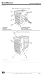
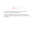
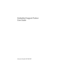
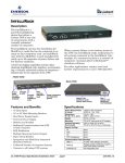
NEC Enterprise Server
NEC Express5800/1000 Series
NEC Express5800/1000 Technology Guide Vol.1
Powered by the Dual-Core Intel® Itanium® Processor
NEC Express5800/1000 Series
Reliabilit y a nd Per for ma nce t h roug h
the f usion of t he N EC “A 3 ” ch ipset a nd
the D u al- Core I ntel ® It a n iu m ® processor
1320Xf / 1160Xf
1080Rf
In today’s fast-paced business environment, all enterprises, from the world’s largest
companies to the smallest depend on IT. Enterprise resource planning ( ERP), customer
relationship management ( CRM ), and business intelligence ( BI ) all require that transactions
are quickly processed and that the resulting data is reliable as to meet the requirements of the
rapidly changing business environment. The need for higher per formance and better reliability
is growing exponentially in enterprise IT platforms.
People no longer consider mainframe systems and vector supercomputers as open enterprise
IT platforms. However if one were able to have supercomputer per formance and mainframe
reliability for the cost of an open ser ver in a datacenter, many may reconsider.
Next generation enterprise IT platform
NEC Enterprise Server
Express5800/1000 series
Leveraging NEC’s vector supercomputer and mainframe technology, Express5800 /1000 series
is designed to meet the requirement of today’s mission critical enterprises.
With the new Dual-Core Intel ® Itanium ® processor 9000 series and the NEC designed
third generation chipset “A 3 ”, from chipset, board to system-level design, NEC has never
compromised to realize mainframe-class reliability and supercomputer-class per formance.
Express5800 /1000 series is the per fect IT platform for the most demanding mission critical
enterprises.
Supercomputer-class Performance
• High processing power by the Dual-Core Intel ® Itanium ® processor:
Dual-Core, massive L3 cache and EPIC (Explicitly Parallel Instruction Computing) architecture
• Very Large Cache (VLC) Architecture:
High-speed / low latency Intra-Cell cache-to-cache data transfer
• Dedicated Cache Coherency Interface (CCI):
High-speed / low latency Inter-Cell cache-to-cache data transfer
• Crossbar-less configuration (Available only on 1080Rf):
Improved data transfer latency through direct attached Cell configuration
Flexibility and Operability
• Resource virtualization through Floating IO:
Flexible resource management allows for robust server virtualization
• Multi-OS Support / Rich application lineup:
Supports Windows ® and Linux operating systems
• Superior standard chassis configuration: Small footprint and highly scalable IO
2
n I nternal Connections of the
Express5800/1000 Series
n S ystem Hardware Layout of the Express5800/1000
Series Server (1320Xf)
Increased inter-Cell data transfer speeds
Fan box
l
el
Crossbar
card
Cell card
* R edundant
configuration
available
l
C
el
Cell
Cell
ll
Clock card * 1
e
HDD Bay
High-speed crossbar
l
C
el
Processor
Processor
Fan box
C
Direct data transfer of large cache data
Service
Processor * 1
C
Cache Coherency Interface (CCI)
Cell
Cell Controller
Processor
PCI slots
* R edundant
configuration
available
Power
Distribution
Unit (PDU)
A3 Chipset
Processor
Memory
PCI box
Power Bay
Service Processor
Fan box
Clock card
Cell card
HDD Bay
PCI box
Power Distribution Unit
Crossbar card
Power Bay
PCI slots
Hot Pluggable *2
Fully
Redundant
N+1
Redundant
*1 R edundancy is optional
*2 A bility to replace a failed component
without shutting down other partitions
Memory
Mainframe-class RAS features
Reliability / Availability
• Dual-Core Intel ® Itanium ® processor:
Error handling of hardware and operating system through Machine Check Architecture (MCA)
• Memory mirroring: Continuous operation even in the event of a non-correctable error
• Partial Chipset degradation: Avoid multi-partition shutdowns resulting from chipset failures
• Highly Available Center Plane: System restoration after the replacement of a failed crossbar no longer requires a system shutdown
• Complete modularization and redundancy: Improvements in fault resilience, continuous operation and serviceability
• Clock modularization, redundancy and 16 processor domain segmentation:
Minimizes downtime, and avoids multi partition shutdown due to clock failure
• Diagnostics of the error detection circuits: Substantial strengthening of data integrity
• Enhanced error detection of the high-speed interconnect:
Intricate error handling through multi bit error detection and retransmission of error data
• Two independent power sources: Avoid system shutdown due to failures of the power distribution units
Serviceability
• Autonomic reporting of logs with pinpoint prognosis of failed components allow for the realization of mainframe-class platform serviceability
3
Supercomputer-class Performance
Features for performance improvement
ual-Core Intel ® Itanium ® processor and high-speed D
inter/intra Cell cache-to-cache data transfer
At the heart of the Express5800/1000 series server is the
64-bit Dual-Core Intel ® Itanium ® processor, redesigned for
Increased Memory Bandwidth
even faster processing of larger data sets.
Improved Inter/Intra-Cell memory data transfer
The system has been equipped with the NEC designed chipset,
Very Large Cache (VLC) Architecture
“A 3 ”, in order to improve performance by utilizing, to its full
High-speed/low latency Intra-Cell cache-to-cache data transfer
extent, the massive 24MB of cache memory that has been built
Dedicated Cache Coherency Interface (CCI)
into the Dual-Core Intel ® Itanium ® processor
High-speed/low latency Inter-Cell cache-to-cache data transfer
Technologies to increase cache-to-cache data transfer, such
as the VLC architecture and CCI, have been implemented
to maximize the performance for enterprise mission critical
Crossbar-less configuration
[1080Rf]
Improved data transfer latency between Cell/Cell and Cell/IO
computing.
High processing power of the Dual-Core Intel ® Itanium ® processor
Dual-Core, massive L3 cache and EPIC (Explicitly Parallel Instruction Computing) architecture
The Dual-Core Intel ® Itanium ® processor is Intel’s first production
in the Itanium ® processor family with two complete 64-bit cores
on one processor and also the first member of the Intel ® Itanium ®
processor family to include Hyper-Threading Technology, which
provides four times the number of application threads provided by
earlier single-core implementations.
With a maximum of 24MB of On-Die L3 cache, the Dual-Core Intel ®
Itanium ® processor excels at high volume data transactions.
EPIC architecture provides a variety of advanced implementations
of parallelism, predication, and speculation, resulting in superior
Instruction-Level Parallelism (ILP) to help address the current
and future requirements of high-end enterprise and technical
workloads.
Conventional Superscalar
RISC Processor
Original Source Code
Compiler
Parallel processing with
EPIC architecture
Original Source Code
Partial HW
Parallelization
Intel® Itanium®
processor
supported compiler
Intel® Itanium® processor
source is parallelized at
compile time
Sequential
Machine Code
Some level of parallelization is achieved however,
it is not maximized nor efficient
4
Efficient parallel processing
is made possible due to the
thorough parallelization.
Hardware
In the EPIC architecture, parallelization is run at compile time,
allowing for maximum parallelization with minimal scheduling.
[1320Xf]
[1160Xf]
VLC Architecture
High-speed / low latency Intra-Cell cache-to-cache data transfer
The Express5800/1000 series server
implements the VLC architecture, which
Very Large Cache (VLC) Architecture
allows for low latency cache-to-cache
CPU
CPU
CPU
CPU
Cache
Memory
Cache
Memory
Cache
Memory
Cache
Memory
data transfer between multiple CPUs
within a cell.
In a split BUS architecture, for a cacheto-cache data transfer to take place, the
Memory
chipset
FSB
data must be passed through a chipset.
data within the cache memory can
be accessed directly by one another,
bypassing the chipset. This allows
CPU Cache Cache Cache
L3 Memory Memory Memory
CPU
CPU
CPU
Cache
Memory
Cache
Memory
Cache
Memory
Cache
Memory
chipset
Overhead from transferring
data through the chipset.
FSB
CPU Cache Cache Cache
L3 Memory Memory Memory
Dual-Core Intel® Itanium® processor
(Montvale : L3 24MB)
Latency
chipset
This area increases
due to the increase in
cache size and
higher latency
Data Size
Dual-Core Intel® Itanium® processor
(Montvale : L3 24MB)
Latency
for lower latency between the cache
memory, which results in faster data
transfers.
L3 of other CPU
CPU
L3
Cache
Memory
Cache
Memory
CPU
L3
Data Size
Cache
Memory
Higher
latency
(approx 3x)
L3 of other CPU on
different FSB
L3 of other CPU
on same FSB
Cache
Memory
FSB
Latency
degradation
(approx 3x)
L3 of other
CPU on
L3 of
other CPU on different FSB
same FSB
Data Size
Higher cache memory
access latency.
Non-uniform
cache-to-cache data
transfer.
Inconsistent
performance.
Data transfer controller
Intel® Itanium® 2 processor
(Madison : L3 9MB)
Latency
High-speed
cache-to-cache
transfers
L3 of other CPU
CPU
Memory
Direct CPU-to-CPU transfers
Intel® Itanium® 2 processor
(Madison : L3 9MB)
Latency
However, in the VLC architecture,
Split BUS Architecture
Increased enterprise
applications
performance through
reduced cache memory
access latency
Cache
Memory
Cache
Memory
Data Size
This image does not depict actual numbers
Dedicated Cache Coherency Interface (CCI)
High-speed / low latency Inter-Cell cache-to-cache data transfer
Another technology implemented in the Express5800/1000 series
The benefit of the TAG based mechanism, thus implemented in
server to improve cache-to-cache data transfer is the Cache
the Express5800/1000 series server, is that by accessing the
Coherency Interface (CCI). CCI, the inter-Cell counterpart of the
TAG, unnecessary inquiries to the cache memory are filtered for a
VLC architecture, allows for a lower latency cache-to-cache data
smoother transfer of data. Furthermore, the Express5800/1000
transfer between Cells.
series server includes a dedicated high-speed cache coherency
Information containing the location and state of cached data is
required for the CPU to access the specific data stored in cache
memory. By accessing the cache memory according to this
information, the CPU is able to retrieve the desired data.
interface (CCI) which is used to connect the Cells directly to
one another without using a crossbar. This interface is used for
broadcasting and other cache coherency transactions to allow for
even faster cache-to-cache data transfer.
Two main mechanisms exist for cache-to-cache data transfer
Tag Based Cache Coherency
between Cells, directory based and TAG based cache coherency.
Request is broadcasted to all CPU
simultaneously
The cache information, described above, is stored in external
memory (DIR memory) for the directory based, and within the
chipset for the TAG based mechanisms.
In a directory based system, the requestor CPU will first access the
external memory to confirm the location of the cached data, and
then will access the appropriate cache memory. On the other hand,
in a TAG based system, the requestor CPU broadcasts a request to
all other cache simultaneously via TAG.
CPU CPU CPU CPU
chip
set
TAG
Memory
CPU CPU CPU CPU
chip
set
TAG
Memory
CPU
CPU CPU CPU CPU
chip
set
TAG
Memory
Access Directory to confirm the location of
the data first, then access the appropriate
cache memory
Memory
CPU CPU CPU CPU
chip
set
Memory
DIR
CPU CPU CPU CPU
chip
set
DIR
chip
set
TAG
CPU
chip
set
chip
set
CPU
Performance
increase with
the A 3 chipset
Directory Based Cache Coherency
CPU
chip
set
chip
set
Memory
chip
set
chip
set
CPU
chip
set
chip
set
CPU
CPU requesting the information
CPU
CPU storing the newest information
Memory
Directory Based Cache Coherency
chip
set
chip
set
CPU
DIR
The Express5800/1000 Series server
implements a dedicated connection (CCI)
for snooping
CPU CPU CPU CPU
A 3 Chipset
Memory that is storing location regarding
the memory
TAG
TAG memory (Manages cache line
information for all of the CPUs loaded on a
CELL card)
DIR
DIR Memory (Manages cache line
information for all of the memory loaded on
a CELL card)
Memory
DIR
Crossbar-less configuration
Improved data transfer latency through direct attached Cell configuration
Within the Express5800/1000 series server lineup, the 1080Rf
Even with the crossbar-less configuration, virtualization of the Cell
has been able to lower the data transfer latency by removing the
card and I/O box has been retained as not to diminish computing
crossbar and directly connecting Cell to Cell, and Cell to PCI box.
and I/O resources.
5
Mainframe-class RAS Features
RAS Design Philosophy
Realization of a mainframe-class continuous operation through the pursuit of reliability and availability in a single server construct
Generally, in order to achieve reliability and availability on an
Continuous operations throughout failures; minimize the
open server, clustering would be implemented. However,
spread of failures; and smooth recovery after failures were
clustering comes with a price tag. To keep costs at a minimum,
goals set forth which lead to implementation of technologies
the Express5800/1000 series servers were designed to
such as memory mirroring, increased redundancy of intricate
achieve a high level of reliability and availability, but within a
components, and modularization. Through these technologies
single server.
a mainframe level of continuous operation was achieved.
The Express5800/1000 series server’s powerful RAS features
were developed through the pursuit of dependable server
technology.
Reliability
Improved reliability and availability as a stand alone server
Improved system availability
Clustering
Mainflame
Level
Dependable Server Technology
Redundant components, error prediction and error
correction allows for continuous operation
Conventional
open server
Level
Technology to minimize the effects of hardware failures on
the system. Reduction of performance degradation and
multi-node shutdown
Ability to replace failed components without
shutting down operations
PC Server
Level
Serviceability
No chipset on the center plane
ECC protection of main
data paths Intricate error
detectionof the highspeed interconnects
Hot Pluggable*4
Clock
Duplexed* 1
16 processor domain
segmentation* 2
Hot Pluggable*4
Core I / O
Core I/O Relief
Hot Pluggable*4
Hot Pluggable*4
PCI card
Memory
ECC protection
SDDC Memory
CPU
Intel® Cache Safe
Technology* 3
L3 cache
Smooth recovery after failures
Availability
Partial chipset degradation/
Dynamic recovery
Chipset
Continuous operations through failures
Minimized spread of failures
Center
plane
Memory
Mirroring*1
Power
N+1 Redundant
Two independent
power sources
Hot Pluggable*4
HDD
Software RAID
Hardware RAID
Hot Pluggable*4
*1 Available only on the 1320Xf/1160Xf
*2 Available only on the 1320Xf
*3 Intel® technology designed to avoid cache based failures
*4 Replacement of failed component without shutting down other partitions.
The Dual-Core Intel ® Itanium ® processor MCA
(Machine Check Architecture)
The framework for hardware, firmware and OS error handling
The Dual-Core Intel ® Itanium ® processor, designed for high-end
enterprise servers, not only excels in performance, but is also
abundant in RAS features. At the core of the processor’s RAS
Application Layer
Operating System
The OS logs the error, and then starts the recovery process
feature set, is the error handling framework, called MCA.
MCA provides a 3 stage error handling mechanism – hardware,
firmware, and operating system. In the first stage, the CPU and
Firmware
chipset attempt to handle errors through ECC (Error Correcting
Seamlessly handles the error
Code) and parity protection. If the error can not be handled by
the hardware, it is then passed to the second stage, where the
firmware attempts to resolve the issue. In the third stage, if the
error can not be handled by the first two stages, the operating
system runs recovery procedures based on the error report
and error log that was received. In the event of a critical error,
the system will automatically reset, to significantly reduce the
possibility of a system failure.
6
Hardware
CPU and chipset ECC and parity protection
The Firmware and OS aid in the correction of complex platform errors to restore the system
Error details are logged, and then a report flow is defined for the OS
Detects and corrects a wide range of hardware errors for main data structures
Memory Mirroring
Continuous operation even in the event of a non-correctable memory error
The Express5800/1000 series server supports high-level memory
RAS features to ensure that the server can rapidly detect memory
CPU
errors, reduce multi-bit errors and continually operate even in
CPU
CPU
CPU
the event of memory chip or memory controller failures. Memory
Memory
I/F
Memory
Controller
Memory
I/F
Memory
Controller
Data 2
Cell
Controller
examples of those features.
Data 0
Memory
Image
scan, memory chip sparing (SDDC*) and memory scrubbing are
Data 0
Data 2
Data 3
Memory
Controller
Memory
Controller
Data 3
Memory
I/F
Chip sparing (SDDC*) memory is a memory system loaded with
Data 1
possible downtime during business operations.
Mirror
is immediately isolated and detached from the system preventing
Mirror
boot. If the system detects a memory failure, the failed component
Data 1
A memory scan is run on all loaded memory modules at each OS
several DRAM chips that can correct errors at the chip level. If
a failure were to occur in the memory, the error can be corrected
Memory
I/F
immediately to allow for continuous operation.
Memory scrubbing checks memory content regularly (every few
milliseconds) during operation without affecting performance.
When an error is detected, it is corrected and then reported.
Components covered by
the memory mirroring
Components covered by
the standard chip sparing
Unit of degradation
on the Express5800/
1000 Series
The scrubbing function is effective in detecting errors in a timely
manner which ultimately results in the reduction of multi-bit errors.
Memory mirroring takes place continuously, where the same data
is written onto 2 separate memory blocks instead of 1 (available
only on the 1160Xf and 1320Xf). In the event of a non-correctable
error, due to the fact that the data exists on two independent
This construct allows for continuous operation through all noncorrectablememory errors, not limited to the memory themselves,
but also in the memory interfaces and the in memory controllers.
* Single Device Data Correction
blocks, operations are able to continue without interruption.
Partial Chipset degradation
Avoid multi-partition shutdowns resulting from chipset failures
In certain instances when multiple server partitions share a
common crossbar controller, effects of a single partition failure
may result in a multi-partition shutdown. To resolve this issue, the
Express5800/1000 series servers have been designed to allow for
0
1
Cell 0
Cell 1
the partial degradation of chipsets.
Partial
degradation
Within each of the LSI chips, which make up the chipset, multiple
Failure
LSI sub-units exist. These sub-units are connected to other subunits located on separate LSI chips. The combined sub-units
together make up single partition. If an error were to occur on an
Sub
Unit
Sub
Unit
Sub
Unit
Sub
Unit
Crossbar
Controller
A
Sub
Unit
Sub
Unit
Sub
Unit
Sub
Unit
Crossbar
Controller
B
LSI sub-unit, that sub-unit alone can be degradated to isolate the
failure to a single partition, thus preventing the failure to spread to
other partitions.
PCIBox
PCIBox
0
1
Furthermore, the downed partition can automatically reboot
itself, after isolating the failed subsystem, to resume operations
0
in a degradated mode without the intervention of a system
administrator. This is made possible, on the Express5800/1000
series servers, by the redundant paths between the Cells and the
IO.
0
Sub
Unit
1
n specifies the partition number
Sub-units within the chipset
Additional sub-sets exist in
actuality
1
Failure occurs at the sub-unit of
the crossbar controller.
Partition 0 is shutdown so that the
failed component can be isolated.
Partition 0 is rebooted
Not affected
7
Mainframe-class RAS Features
Highly Available Center Plane
System restoration after the replacement of a failed crossbar card no longer requires a planned system downtime
The Express5800/1000 series server has separated and
Crossbar Controller Mudularization
Only the node that is linked directly to the failed crossbar
will be temporarily shutdown
modularized the crossbar controller which ordinarily would reside
on the system center plane. By moving the crossbar controller off
of the center plane, a reduction in center plane failures has been
realized.
Failure
Failure
Crossbar
Controller
(LSI)
during the replacement of the crossbar card.
(The 1080Rf has a crossbar-less configuration.)
Cell
Down
The failed crossbar
card can be
replaced without halting
other business
operations.
Cell
Cell
Cell
Cell
Cell
Down
the other partitions to continue operations uninterrupted, including
Crossbar
Card
Cell
linked to the crossbar will be temporarily shutdown, allowing for
Cell
In the unlikely event of a crossbar failure, only the partition that is
Complete modularization and redundancy
Improvements in fault resilience, continuous operation and serviceability
Major components of the Express5800/1000 series servers have
been modularized, allowing for better serviceability and easy
Front Side
Back Side
replacement in the event of a component failure.
Fan box
Furthermore, to minimize the existence of single point of failure,
Fan box
Service
Processor
many of these modules have redundancy, allowing for continuous
operations (fault resilience).
Clock
card
Cell card
Fan box
Crossbar
card
Cell card
PCI Module
Fan box
PCI Box
HDD Module
Operation 2 Spare
Node 2 Cell Card
Operation 1
Node 1
Operation 3
Node 3
Cell card
Cell card
Cell card
Cell card
Cell card
Cell card
Cell card
CPU
CPU
CPU
CPU
CPU
CPU
CPU
CPU
CPU
CPU
CPU
CPU
CPU
CPU
CPU
CPU
CPU
CPU
CPU
CPU
CPU
CPU
CPU
CPU
CPU
CPU
CPU
CPU
Memory
Memory
Memory
Memory
Memory
Memory
Memory
Memory
Memory
Memory
Memory
Memory
Memory
Memory
PCI box
Crossbar Card
Crossbar Card
Crossbar Card
Crossbar Card
PCI box
PCI box
PCI box
PCI box
Clock Card
PCI box
Clock Card
Service Processor
Cooling fan (N+1 redundant)
Power supply (N+1 / 2N redundant)
8
Operation 4
Node 4
Power
Distribution
Unit
Sample: Express5800/1320Xf
Redundant Crossbar
Redundant Clock Module
(Redundancy or Segmentation)
Redundant service processor
N+1 redundant cooling fan
N+1 redundant power supply
Quick recovery is possible
with a spare CELL card
1080Rf is crossbar-less
Full redundancy is available on the
1320Xf/1160Xf. Segregation is available
on the 1320Xf
Available on the 1320Xf/1160Xf
2N is included in the 1320Xf, and is offered
as an option on the 1160Xf/1080Rf
* This picture illustrates a 1320Xf
Modularization, redundancy and domain segmentation of the system clock
Minimizes downtime, and avoids multi-partition shutdown due to clock failure
Through modularization and redundancy, system downtime, due to
the oscillator, but also in the clock distribution mechanisms so that
clock failures, have been minimized. The Express5800/1000 series
system downtime can be minimized.
server has taken it one step further. In many cases, when a system
is said to have a redundant clock, in actuality, only the oscillator
is redundant. Integral clock distribution mechanisms such as the
clock driver or the amplifier are, many times, not redundant. Such
a construct leads to the existence of system single point of failures.
The Express5800/1000 series servers have redundancy in not only
Express5800/1000 Series
Redundant: Active, Standby
chipset
chipset
16 Processor Domain
Segmentation
16 Processor
Domain
16 Processor
Domain
chipset
chipset
The 1320Xf system allows for the division of the system into two
16 processor segments, where one segment utilizes one system
clock, and the other 16 processor segment utilizes the remaining
system clock. A failure in a system clock therefore, will not result
in shutdown of the entire system.
Redundant Configuration A
Redundant Configuration B
Redundant: Active, Standby
Redundant: Active, Standby
chipset
chipset
chipset
chipset
SPOF
Hot
pluggable
Clock
Distribution
Clock
Distribution
Clock
Distribution
Clock
Distribution
Clock
Distribution
Clock
Module
Clock
Module
Clock
Module
Clock
Module
Clock
Module
Not hot
pluggable
Express5800/1000 Series
Replacement of failed
component without
system halt
Minimized spread
of failure
Clock
Distribution
Clock
Module
Redundant Configuration A
Clock
Module
Clock
Module
Redundant Configuration B
Redundant
*1
Available on the 1320Xf/1160Xf
16 processor Domain Segmentation
Available on the 1320Xf
*1: Hot plugging of the redundant oscillator is possible, however the hot plugging of the single clock driver is not possible
Diagnostics of the error detection circuits
Substantial strengthening of data integrity
Main data paths of the A 3 chipset on the Express5800/1000 series
CPU
servers have been protected by ECC. When a single bit error is
CPU
detected, a hardware error correction is carried out. Furthermore,
paths between the A 3 chipset interfaces support multi-bit error
detection, and resending of errored data.
In addition to maintaining data integrity through these RAS
CPU
CPU
Memory
Controller
To
other CELL
controller
Cell
Controller
Memory
Controller
Memory
Controller
Memory
Controller
features, the Express5800/1000 series server has the ability to
run diagnostics on its own error detection circuits. During every
system boot, all error detection circuits are diagnosed for possible
Cell card
Crossbar
Controller
Crossbar
Controller
Crossbar
Controller
Crossbar
Controller
Built-in high-speed error
check for inter-chipset
paths
Crossbar Card
failures. Without this feature, a failure in these circuits could result
in the inability to detect errors during system operation.
I/O
Router
I/O
Router
PCI BOX
9
Mainframe-class RAS Features
Enhanced error detection of the high-speed interconnect
Intricate error handling through multi-bit error detection and resending of errored data
Since higher speed interconnects are implemented to increase
Without Check Features
system performance, there are higher probabilities that
interference noise will cause errors occurring along these
Logic Circuits
chipset
Data
interconnects. One method of handling these interconnect errors
1 bit Error
ECC
Error
Reporting
Error Detection
Circuits
would be to disable the errored interconnect and operate in a
Failure
degradated mode.
Bad data, resulting from a simple error
such as a single bit error, can not be
blocked if a failure exists within the
error detection circuits themselves.
Unable to detect error
Bad Data
In addition to above method, the Expres5800/1000 series servers
Without Check Features
have implemented a methodology prevalent in supercomputers,
Diagnostics of the error detection
circuits at every system boot
insures data integrity.
Logic Circuits
where by intricate multi-bit error detection is carried out, and
Data
errored data is resent upon detection of an error. This allows
the Express5800/1000 series servers to handle the intermittent
ECC
Error Detection
Circuits
errors which occur along the high-speed interconnects, without
Failure
Circuit
Check
impacting the system performance.
Error
Reporting
Error Detected
Two independent power sources
Avoid system shutdown due to failures of the power distribution units
The previous 32 processor and the 16 processor models supported
Implementation of an Uninterruptible Power Supply (UPS) can
having two independent power supplies, where the 8 processor
further increase availability. The two independent power source
model did not. This feature is now available on the new 8 processor
feature is a standard feature on the 1320Xf and is available as an
system (1080Rf) so that the system can continue operations even
optional feature for 1160Xf and 1080Rf.
in the event of a failure with in the power distribution unit.
Autonomic reporting of error logs with pinpoint prognosis
of failed components
Realization of a mainframe-class platform serviceability
The Express5800/1000 series servers are equipped with a service
processor which process server management and platform error
Customer
Environment
handling. The service processor can be considered the core
component which supports the RAS features of the system. One
Diagnostics
Agent
feature of the service processor is its ability to analyze detail logs
(BID: built-in diagnosis) which are collected by the chipset in the
event of an error. The BID is able to diagnose the location of the
error, and will pinpoint the required FRU (Field Replaceable Unit)
so that the time required to replace the component and recover the
system, can be minimized.
In the event of a failure, the Express5800/1000 series servers
also have the capability to automatically send detailed error logs
to maintenance personnel, enabling us to further lessen the time
required to resolve a system error. Furthermore, to minimize
the possibility of a critical error, the diagnostics engine is able to
proactively predict errors rather than just react to errors.
10
The error information summary
is analyzed to determine the
cause of the failure.
The development team may
be contacted for assistance.
Diagnostics Agent
Hard
ware
Diagnostics of retry tendency and
confirmation of whether threshold
,
ance
was exceeded
inten cement
e Ma
la
entiv ent Rep
v
re
n
P
mpo
d Co
Faile
Maintenance Group
Log
Mail
Encrypted message
Service
Processor
Internet
Log
If required, the detail log is analyzed
further by the development groups
Manager
Log
A detailed hardware error log
including transaction history is
collected.
Mail
The Error information
is sent via email
Development Group
Flexibility and Operability
Pursuit of flexibility and operability in a system
— Flexible resource virtualization using floating I/O for improved operability
Investment Protection
Smooth migration to future processors
The Express5800/1000 series servers now support the Dual-Core
� Intel® Itanium® Processor Family Roadmap
Intel ® Itanium ® processors with two complete 64-bit cores on
2002
2003
2004
each processor. From the beginning of development, state-of-theart technologies have been built into the Itanium ® processors to
answer to the stringent levels of throughput, scalability, reliability,
and availability that are required by the server platforms, and
Intel ® Itanium ® 2
processor 1GHz,
3MB L3
also provided top-level performance. With the deployment of the
Intel ® Itanium ® 2
processor 1.5GHz,
6MB L3
Intel ® Itanium ® 2
processor 1.6GHz,
9MB L3
2006
2007
Future
Dual-Core Intel ® Itanium ® 2
processor 1.6GHz,
24MB L3
Tukwila*
Dual-Core Intel ® Itanium ®
processor 1.6GHz,
24MB L3
present day Dual-Core system, a smooth migration to future multicore systems can be assured.
* Intel codenames
Resource virtualization through floating I/O
Flexible resource management allows for robust server virtualization
The Express5800/1000 series employ floating I/O to allow for
Insufficient computing
resources
the flexible combination of Cell cards and PCI boxes (I/O). The
Cell card
computational and I/O resources can be virtualized, allowing for
the flexibility to reallocate system resources into the most optimal
Resource pool
Cell card
Cell card
Crossbar
configuration according to operation or load.
PCI box
PCI box
Furthermore, with the existence of a spare Cell card, the system
can swap the failed Cell card with the spare in the event of a failure,
Insufficient I/O
resources
Problem resolved by adding
additional computing resources
and reboot the system so that business operation can resume
Cell card
without loosing valuable computational resources.
PCI box
Cell card
Cell card
Crossbar
PCI box
PCI box
PCI box
Problem resolved by adding
additional I/O resources
Multi OS support / Rich application lineup
Windows ® operating system and Linux operating systems supported
Along with the industry’s prevalent Microsoft ® Windows ® operating
With the inception of the Itanium ® Solutions Alliance (ISA),
system,the Express5800/1000 series servers also support the
whose main objective is to promote the advancement of
Linux operating system. By dividing the system into multiple
Itanium ® -based solutions, applications streamlined to perform
partitions, it is possible to support multiple operating systems
on the Itanium ® -based servers, such as the Express5800/1000
within a single server.
series servers, have increased considerably.
Superior standard chassis configuration
Small footprint and a highly scalable I/O
With the ability to load 32 Dual-Core Intel ® Itanium ® processors
the Express5800/1000 series server, it is an ideal candidate for
(1320Xf) into an industry standard 19-inch rack footprint, the
replacement or consolidation of older systems.
Express5800/1000 series server has proved to have the industries
highest level of performance per unit area. Because additional
space is not required in the datacenter in order to accommodate
The 1080Rf is a very compact 8U model which can support up to 8
internal 3.5 inch HDD and 16 PCI cards.
11
n NEC Express5800/1000 series Specifications
Model
1080Rf
1160Xf
CPU
Intel ® Processor Number
Clock frequency
9120N
9140N
9150N
9120N
9140N
9150N
9120N
9140N
9150N
1.42GHz
1.60GHz
1.60GHz
1.42GHz
1.60GHz
1.60GHz
1.42GHz
1.60GHz
1.60GHz
Maximum Number of CPU(core)
8 (16)
16 (32)
L1 Cache/core
On-chip cache
32 (64)
16KB (I) / 16KB (D)
L2 Cache/core
1MB (I) / 256KB (D)
L3 Cache/core
6MB
9MB
12MB
6MB
9MB
12MB
6MB
9MB
12MB
L3 Cache/CPU
12MB
18MB
24MB
12MB
18MB
24MB
12MB
18MB
24MB
Maximum Memory Capacity
Maximum Number of I/O slots
Internal Disk
Drives
1320Xf
Dual Core Intel ® Itanium ® processor
Processor
Disk Bay
Maximum Capacity
128GB
512GB
1TB
16
32
32/64
8
16
16/32
2,400GB (300GB * 8)
4,800GB (300GB * 16)
9,600GB (300GB * 32)
LAN Interface
Cabinet Type
Dimension (W * D * H)
Weight
Power Supply
ES Temperature/Humidity
Supported OS
10/100Base-T (For Management console)
Rack mount (8U)
Standalone (37U)
441 x 857 x 351 mm
600 x 1070 x 1800 mm
110kg
464kg
563.4kg
AC 200-240V / 50Hz-60Hz
5 – 35 degree C / 20 – 80 % RH (operation), 5 – 45 degree C /8 - 80 % RH (non-operation) without condensation
Microsoft ® Windows Server ® 2008 for Itanium-based Systems
Microsoft ® Windows Server ® 2003 Enterprise Edition / Datacenter Edition
Red Hat Enterprise Linux
* NEC is a registered trademark and Empowered by Innovation a trademark of NEC Corporation and/or one or more of its subsidiaries. All are used under license. * Intel, Intel logo, Itanium and
Itanium inside are trademarks or registered trademarks of Intel Corporation or its subsidiaries in the United States and other countries. * Microsoft and Windows are registered trademarks or
trademarks of the US Microsoft Corporation in the United States and other countries. * Red Hat and Shadow Man logos are registered trademarks or trademarks of Red Hat Inc. in the United States
and other countries. * Linux is a trademark or registered trademark of Linus Torvalds in the United States and other countries. * All other trademarks and registered trademarks are the property of
their respective owners.
Safety notes
Please read carefully before use and observe the cautions and prohibitions in the instruction, installation, planning, operations and other manuals.
Incorrect usage may cause fire, electric shock, or injury.
Company names and product names used in this catalogue are trademarks or registered trademarks of the respective companies.
If this product (including the software) comes under the regulations of Foreign Exchange and Foreign Trade Law as a regulated article or other item, observe the procedures (such as application for
export permission) required by the Japanese government when taking the product out of Japan.
The colors of the products in this catalogue may be slightly different from the actual colors. Specifications are subject to change without prior notice for the purpose of improving the product.
© 2008 NEC Corporation. All rights reserved.
Information in this document is subject to change without notice.
Cat .No.E07H001