1
! CAUTION
This manual is provided for reference only. It does NOT provide
instructions on how to operate your chamber.
The Series F4 Temperature Controller uses the Modbus protocol for
communications. Only the applicable sections related to Modbus in this
manual apply.
Data Communications Reference
Electronic User’s Manual
ISO 9001
Registered Company
Winona, Minnesota USA
Watlow Controls
1241 Bundy Blvd., P.O. Box 5580, Winona, Minnesota USA 55987-5580, Phone: (507) 454-5300, Fax: (507) 452-4507
WTCDCE_A.pdf
June 1998
Made in the U.S.A.
$15.00
Safety Information
We use note, caution and warning symbols
throughout this book to draw your attention to
important operational and safety information.
A “ NOTE” marks a short message to alert you to
an important detail.
A “CAUTION” safety alert appears with
information that is important for protecting your
equipment and performance. Be especially careful
to read and follow all cautions that apply to your
application.
information that is important for protecting you,
others and equipment from damage. Pay very close
attention to all warnings that apply to your
application.
, (an exclamation point
The safety alert symbol,
in a triangle) precedes a general CAUTION or
WARNING statement.
, (a lightning bolt
The electrical hazard symbol,
in a triangle) precedes an electric shock hazard
CAUTION or WARNING safety statement.
A “WARNING” safety alert appears with
Technical Assistance
If you encounter a problem with your Watlow
controller, review all of your configuration
information to verify that your selections are
consistent with your application: inputs; outputs;
alarms; limits; etc. If the problem persists after
checking the above, you can get technical assistance
from your local Watlow representative, or by
dialing (507) 454-5300, ext. 1111. An applications
engineer will discuss your application with you.
Please have the following information
available when calling:
• Complete model number (from the label on the
side of the controller)
• All configuration information,
User Profile Record, Custom Main Page Record
and Operations Page Parameter Record
• User’s Manual
• Diagnostic Menu readings (if applicable)
About Watlow Controls
Watlow Controls is a division of Watlow Electric
Mfg. Co., St. Louis, Missouri, a manufacturer of
industrial electric heating products since 1922.
Watlow begins with a full set of specifications and
completes an industrial product that is manufactured in-house, in the U.S.A. Watlow products
include electric heaters, sensors, controllers and
switching devices. The Winona operation has been
designing solid-state electronic control devices since
1962, and has earned the reputation as an excellent
supplier to original equipment manufacturers.
These OEMs and end users depend upon Watlow
Controls to provide compatibly engineered controls
that they can incorporate into their products with
confidence. Watlow Controls resides in a 100,000square-foot marketing, engineering and manufacturing facility in Winona, Minnesota.
Your Feedback
Your comments or suggestions on this manual are
welcome. Please send them to the Technical
Literature Team, Watlow Controls, 1241 Bundy
Blvd., P.O. Box 5580, Winona, Minnesota, 55987-
5580; phone: (507) 454-5300; fax: (507) 452-4507.
The Watlow Controls Data Communications Guide
is copyrighted by Watlow Winona, Inc., © June 1998,
with all rights reserved. (1454)
T
Table of Contents
Chapter 1
Chapter 4
Audience . . . . . . . . . . . . . . . . . . . . . . . . . . . 4
Write Your Own (HMI) . . . . . . . . . . . . . . . . .12
Media . . . . . . . . . . . . . . . . . . . . . . . . . . . . . .4
Purchase an HMI package . . . . . . . . . . . . .18
Purpose . . . . . . . . . . . . . . . . . . . . . . . . . . . .4
Chapter 5
Getting Started . . . . . . . . . . . . . . . . . . . . . . .4
Interface Adapters . . . . . . . . . . . . . . . . . . .20
Convention . . . . . . . . . . . . . . . . . . . . . . . . . .4
Watlow Software Tools . . . . . . . . . . . . . . . .20
Chapter 2
922 Comm Diagnostic . . . . . . . . . . . . . . . .21
Elements of Machine to Machine Comm. . . .5
Comm4 Diagnostic Software . . . . . . . . . . . .21
Character Format . . . . . . . . . . . . . . . . . . . . .5
Comm5vb Diagnostic Software . . . . . . . . . .21
Bits and Bytes . . . . . . . . . . . . . . . . . . . . . . .5
CRC . . . . . . . . . . . . . . . . . . . . . . . . . . . . . .21
ASCII . . . . . . . . . . . . . . . . . . . . . . . . . . . . . .5
Interface Comparison . . . . . . . . . . . . . . . . .22
ASCII Chart . . . . . . . . . . . . . . . . . . . . . . . . .6
Controller Comparison Summery . . . . . . . .22
Serial Communication . . . . . . . . . . . . . . . . . .7
Appendix
Parity Bits . . . . . . . . . . . . . . . . . . . . . . . . . . .7
Glossary . . . . . . . . . . . . . . . . . . . . . . . . . . .23
Start and Stop Bits . . . . . . . . . . . . . . . . . . . .8
Disclaimer of Warranty . . . . . . . . . . . . . . . .28
Baud Rate . . . . . . . . . . . . . . . . . . . . . . . . . .8
Computer Languages . . . . . . . . . . . . . . . . . .8
Syntax . . . . . . . . . . . . . . . . . . . . . . . . . . . . .8
Chapter 3
Interface Standards . . . . . . . . . . . . . . . . . . .9
Wiring . . . . . . . . . . . . . . . . . . . . . . . . . . . . .9
Biasing of Buses . . . . . . . . . . . . . . . . . . . . . .9
Interface Converters . . . . . . . . . . . . . . . . . .10
Protocols . . . . . . . . . . . . . . . . . . . . . . . . . .10
A downloadable electronic copy of this user manual is available free of charge through Watlow's web site:
http://www.watlow.com/prodtechinfo
Watlow Controls Communication Guide
3
5. Configure the PC or PLC software
and hardware to do what you want
them to do.
Chapter One Introduction
The first step is the most difficult since
decisions need to be made before anything
is purchased. It really involves three basic
items:
1. Determine how many controllers
you will communicate with.
2. Pick a protocol and interface that
supports the information exchange.
3. Purchase hardware and software to
make this happen.
Audience
The document is targeted towards new
users interested in using data
communications with Watlow controllers.
Media
This document is available in electronic
format only. It is viewable using Adobe
Acrobat Reader available free from the
Adobe site www.adobe.com on the
World Wide Web.
This document will only deal with the task
of communication. Refer to the user’s
manuals for each product for information
about wiring and configuring the
controllers and software.
Purpose
Convention
The purpose of this document is to enable
users to:
1. Understand the basics of serial data
communications via standard
definitions, interfaces and protocols.
2. Set up and use a simple network of one
Watlow controller.
3. Set up and use a network of two or
more Watlow controllers with HMI
(human-machine interface) software
or an operator interface panel.
In this document, numbers in the format
0x00 represent values in hexadecimal.
Numbers in the format 0 represent values
in decimal and finally, numbers in the
format 00000000 represent values in
binary unless stated otherwise.
Getting Started
Your task is to get one or more controllers
to talk to a PC or PLC. How do you make
this happen? The purpose of this
document is to assist you in that task by
providing information about
communications. The task of getting a PC
or PLC communicating with controllers is
a five step process:
1. Determine a strategy for
communications.
2. Purchase a controller with a
communication interface and
protocol that supports your
strategy.
3. Wire controllers for power, control
and communication.
4. Configure the controllers to do
what you want them to do.
Watlow Controls Communications Guide
4
Bits and Bytes
Chapter 2 Definition of Terms
The word bit is simply the contraction of
the words binary digit . A bit is the basic
unit in ASCII. It is either a “1” or a “0”.
A byte is a string of seven or eight bits
that a computer treats as a single
character. ASCII requires seven bits to
represent each letter of the alphabet, each
digit and each punctuation mark we use.
Elements of Machine-toMachine Communication
In human communication there are basic
words and sentences used to get a message
across. Likewise, with computers and
controllers. They need a code called a
character format or character set. They
need rules called protocol to govern their
conversation and prevent confusion and
errors. Computers need a connecting
interface over which to communicate.
They may use one pair of wires to send
information in one direction and another
pair to send in the opposite direction (full
duplex). Or they may use one pair to send
in both directions (half duplex).
ASCII
Character Format
The ASCII code is sometimes written in a
base-16 number system that is called
hexadecimal or “hex” for short. The
numbers 0 through 9 represents the first
ten digits of this system, and the letters A
through F represents the final six digits.
The 128 ASCII character code with the
decimal and hexadecimal equivalents is
listed below.
The ASCII code defines 128 separate
seven- or eight-bit characters (see chart
below), one for each letter, digit and
punctuation mark. ASCII also includes
control characters similar to those we find
on computer keys, such as backspace, shift
and return. It also has nine
communications control characters for
identification, enquiry (inquiry), start of
text, end of text, end of transmission,
acknowledge, negative acknowledge and
escape.
The code or character formats for Watlow
data communication is shared by virtually
everyone in the electronics business
everywhere. This code defines a computer
stream of 1’s and 0’s, that are created by
varying a voltage signal in a regular
manner. The code is the American
Standard Code for Information
Interchange, called ASCII (asky).
Watlow Controls Communications Guide
5
ASCII Chart
ASCII
Char
NUL
SOH
STX
ETX
EOT
ENQ
ACK
BEL
BS
HT
LF
VT
FF
CR
SO
SI
DLE
DC1
DC2
DC3
DC4
NAK
SYN
ETB
CAN
EM
SUB
ESC
FS
GS
RS
US
SP
!
“
#
$
%
&
‘
(
)
*
+
,
.
/
0
1
2
3
4
5
6
7
8
9
:
;
<
=
>
?
Dec
Hex
00
01
02
03
04
05
06
07
08
09
10
11
12
13
14
15
16
17
18
19
20
21
22
23
24
25
26
27
28
29
30
31
32
33
34
35
36
37
38
39
40
41
42
43
44
45
46
47
48
49
50
51
52
53
54
55
56
57
58
59
60
61
62
63
00
01
02
03
04
05
06
07
08
09
0A
0B
0C
0D
0E
0F
10
11
12
13
14
15
16
17
18
19
1A
1B
1C
1D
1E
1F
20
21
22
23
24
25
26
27
28
29
2A
2B
2C
2D
2E
2F
30
31
32
33
34
35
36
37
38
39
3A
3B
3C
3D
3E
3F
No Parity
7 or 8 bit
00000000
00000001
00000010
00000011
00000100
00000101
00000110
00000111
00001000
00001001
00001010
00001011
00001100
00001101
00001110
00001111
00010000
00010001
00010010
00010011
00010100
00010101
00010110
00010111
00011000
00011001
00011010
00011011
00011100
00011101
00011110
00011111
00100000
00100001
00100010
00100011
00100100
00100101
00100110
00100111
00101000
00101001
00101010
00101011
00101100
00101101
00101110
00101111
00110000
00110001
00110010
00110011
00110100
00110101
00110110
00110111
00111000
00111001
00111010
00111011
00111100
00111101
00111110
00111111
7 bit w/ Even
Parity
00000000
10000001
10000010
00000011
10000100
00000101
00000110
10000111
10001000
00001001
00001010
10001011
00001100
10001101
10001110
00001111
10010000
00010001
00010010
10010011
00010100
10010101
10010110
00010111
00011000
10011001
10011010
00011011
10011100
00011101
00011110
10011111
10100000
00100001
00100010
10100011
00100100
10100101
10100110
00100111
00101000
10101001
10101010
00101011
10101100
00101101
00101110
10101111
00110000
10110001
10110010
00110011
10110100
00110101
00110110
10110111
10111000
00111001
00111010
10111011
00111100
10111101
10111110
00111111
7 bit w/ Odd
Parity
10000000
00000001
00000010
10000011
00000100
10000101
10000110
00000111
00001000
10001001
10001010
00001011
10001100
00001101
00001110
10001111
00010000
10010001
10010010
00010011
10010100
00010101
00010110
10010111
10011000
00011001
00011010
10011011
00011100
10011101
10011110
00011111
00100000
10100001
10100010
00100011
10100100
00100101
00100110
10100111
10101000
00101001
00101010
10101011
00101100
10101101
10101110
00101111
10110000
00110001
00110010
10110011
00110100
10110101
10110110
00110111
00111000
10111001
10111010
00111011
10111100
00111101
00111110
10111111
ASCII
Char
@
A
B
C
D
E
F
G
H
I
J
K
L
M
N
O
P
Q
R
S
T
U
V
W
X
Y
Z
[
\
]
^
_
`
a
b
c
d
e
f
g
h
i
j
k
l
m
n
o
p
q
r
s
t
u
v
w
x
y
z
{
|
}
~
DEL
The first digit in bold is the parity bit when enabled.
Watlow Controls Communications Guide
6
Dec
Hex
64
65
66
67
68
69
70
71
72
73
74
75
76
77
78
79
80
81
82
83
84
85
86
87
88
89
90
91
92
93
94
95
96
97
98
99
100
101
102
103
104
105
106
107
108
109
110
111
112
113
114
115
116
117
118
119
120
121
122
123
124
125
126
127
40
41
42
43
44
45
46
47
48
49
4A
4B
4C
4D
4E
4F
50
51
52
53
54
55
56
57
58
59
5A
5B
5C
5D
5E
5F
60
61
62
63
64
65
66
67
68
69
6A
6B
6C
6D
6E
6F
70
71
72
73
74
75
76
77
78
79
7A
7B
7C
7D
7E
7F
No Parity
7 or 8 bit
01000000
01000001
01000010
01000011
01000100
01000101
01000110
01000111
01001000
01001001
01001010
01001011
01001100
01001101
01001110
01001111
01010000
01010001
01010010
01010011
01010100
01010101
01010110
01010111
01011000
01011001
01011010
01011011
01011100
01011101
01011110
01011111
01100000
01100001
01100010
01100011
01100100
01100101
01100110
01100111
01101000
01101001
01101010
01101011
01101100
01101101
01101110
01101111
01110000
01110001
01110010
01110011
01110100
01110101
01110110
01110111
01111000
01111001
01111010
01111011
01111100
01111101
01111110
01111111
7 bit w / Even
Parity
11000000
01000001
01000010
11000011
01000100
11000101
11000110
01000111
01001000
11001001
11001010
01001011
11001100
01001101
01001110
11001111
01010000
11010001
11010010
01010011
11010100
01010101
01010110
11010111
11011000
01011001
01011010
11011011
01011100
11011101
11011110
01011111
01100000
11100001
11100010
01100011
11100100
01100101
01100110
11100111
11101000
01101001
01101010
11101011
01101100
11101101
11101110
01101111
11110000
01110001
01110010
11110011
01110100
11110101
11110110
01110111
01111000
11111001
11111010
01111011
11111100
01111101
01111110
11111111
7 bit w/ Odd
Parity
01000000
11000001
11000010
01000011
11000100
01000101
01000110
11000111
11001000
01001001
01001010
11001011
01001100
11001101
11001110
01001111
11010000
01010001
01010010
11010011
01010100
11010101
11010110
01010111
01011000
11011001
11011010
01011011
01011100
01011101
01011110
11011111
11100000
01100001
01100010
11100011
01100100
11100101
11100110
01100111
01101000
11101001
11101010
01101011
11101100
01101101
01101110
11101111
01110000
11110001
11110010
01110011
11110100
01110101
01110110
11110111
11111000
01111001
01111010
11111011
01111100
11111101
11111110
01111111
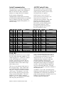
Serial Communication
ASCII Control Codes
The interfaces we’ve chosen employ serial
communication, which is the exchange of
data in a one-bit-at-a-time, sequential
manner on a single data line or channel.
ASCII Control Codes are used to give
instructions to the remote device and
result in specific actions, such as a line
feed instruction on a printer.
Serial contrasts with parallel
communication, which sends several bits
of information simultaneously over multiple
lines or channels. Not only is serial data
communication simpler than parallel, it is
also less costly
ASCII Control Codes, the first 33
ASCII characters (non printable), are
important for the operation of
communicating equipment. They give
instruction to remote devices that
result in specific actions such as a
line feed on a printer Holding down
the keyboard control key while
pressing the appropriate keyboard
key will send these values.
ASCII Dec
Char
Hex
NUL
SOH
STX
ETX
EOT
ENQ
ACK
BEL
BS
HT
LF
VT
FF
CR
SO
SI
DLE
00
01
02
03
04
05
06
07
08
09
0A
0B
0C
0D
0E
0F
10
00
01
02
03
04
05
06
07
08
09
10
11
12
13
14
15
16
Ctrl Key
Equiv.
Crtl @
Crtl A
Crtl B
Crtl C
Crtl D
Crtl E
Crtl F
Crtl G
Crtl H
Crtl I
Crtl J
Crtl K
Crtl L
Crtl M
Crtl N
Crtl O
Crtl P
Definition
ASCII Dec Hex
Char
Null Character
Start of Header
Start of Text
End of Text
End of Transmission
Enquiry
Acknowledge
Bell
Back Space
Horizontal Tabulation
Line Feed
Vertical Tabulation
Form Feed
Carriage Return
Shift Out
Shift In
Data Link Escape
DC1
DC2
DC3
DC4
NAK
SYN
ETB
CAN
EM
SUB
ESC
FS
GS
RS
US
SP
Parity Bit
11
12
13
14
15
16
17
18
19
1A
1B
1C
1D
1E
1F
20
Crtl Q
Crtl R
Crtl S
Crtl T
Crtl U
Crtl V
Crtl W
Crtl X
Crtl Y
Crtl Z
Crtl [
Crtl \
Crtl ]
Crtl |
Crtl _
Definition
Data Control 1 - XON
Data Control 2
Data Control 3 - XOFF
Data Control 4
Negative Acknowledge
Synchronous Idle
End of Trans Block
Cancel
End of Medium
Substitute
Escape
File Separator
Group Separator
Record Separator
Unit Separator
Space
If we were transmitting the lower case “w”
(binary 1110111), the parity bit would be
a 1 because the total number of 1’s in the
character frame is 6, an even number.
Adding the parity bit makes it odd, and
consistent with the odd parity rule.
If a noise spike came onto the data line and
changed the signal voltage level enough to
reverse a 1 to a 0 in the character frame, the
receiver would detect that error. The total
number of 1s would be even and a violation of
the odd-parity rule.
Remember that ASCII is a seven- or eightbit code. What about that eighth bit? It’s
called the parity bit. A parity bit is added
to the ASCII character to verify the
accuracy of the first seven bits. We are
declaring that the number of 1s in the 8bit character frame will be either always
odd or always even.
This way we can detect a single error in
the seven-bit group. Take a look at the
representation of the transmitted upper
case “W.” In this case we have selected
“odd” parity. The number of 1s in the
first seven bits, plus the parity bit, must
always total an odd number. The total
number of 1s in the binary character
1010111 (W) is 5, already an odd number.
Thus our parity bit will be a 0.
Watlow Controls Communications Guide
17
18
19
20
21
22
23
24
25
26
27
28
29
30
31
32
Ctrl Key
Equiv.
At Watlow, we use odd, even and no parity.
Odd parity sets the parity bit to 0 if there are an
odd number of 1s in the first seven bitsEven
parity sets the parity bit to 0 if there are an even
number of 1s in the first seven bits.
No parity ignores the parity bit.
7
Start and Stop Bits
A start bit informs the receiving device
that a character is coming, and a stop bit
tells it that a character is complete. The
start bit is always a 0. The stop bit is
always a 1.
The human speech equivalent of these bits
could be a clearing of the throat to get
someone’s attention (start bit); and a
pause at the end of a phrase (stop bit).
Both help the listener understand the
message.
Baud Rate
The baud rate refers to the data
transmission. When a change in signal
represents one data bit, baud rate is equal
to bits per second (bps). Standard baud
rates for computers are 300, 600, 1200,
2400, 4800, 9600 and 19200 baud.
Computer Languages
Computer languages are simply sets of
symbols and rules for their use. There are
many computer languages and a wide
variety of applications for them.
Programmers use languages to enable
computers to do real work.
Syntax
Syntax for a natural language dictates how
we put words together to make phrases and
sentences. In data communications,
syntax also dictates how we order the parts
of a message.
Watlow Controls Communications Guide
8
common line rather than to a separate
wire, as in EIA-485 and EIA-422. An
EIA-423 cable is limited up to 4,000 feet,
due to noise susceptibility.
Chapter Three Watlow Controls
Approach to Data
Communications
EIA-485 (Half Duplex)
An EIA-485 interface uses three wires: a
T+/R+, a T-/R- and a common line. A -5volt signal is interpreted as a 1, a +5-volt
signal as a 0. As many as 32 remote
devices can be connected to a master on a
multi-drop network up to 4,000 feet long.
Interface Standards
An interface is a means for electronic
systems to interact. It’s a specific kind of
electrical wiring configuration. Four
interfaces are commonly used:
Wiring
Most PCs and some PLCs have a standard
EIA-232 port (usually referred to as RS232). In these instances, you must use an
interface converter to connect to EIA422 or EIA-485. These interface standards
are required to have a multi-drop system
(more than one controller on the bus). See
the list below for some vendors who sell
these converters.
EIA-232 (Full Duplex)
An EIA-232 (formerly RS-232) interface
uses three wires: a single transmit wire; a
single receive wire; and a common line.
Only two devices can use an EIA-232
interface. A -3 to -24 volt signal indicates
a 1 and a +3 to +24 volt signal indicates a
0. The EIA-232 signal is referenced to
the common line rather than to a separate
wire, as in EIA-485 and EIA-422. An
EIA-232 cable is limited to 50 feet, due to
noise susceptibility.
Should your PC or PLC have the
appropriate interface, just connect using
the wiring diagram supplied with your
controller.
For EIA-422, the T+ connects to the R+,
sometimes labeled “B” while the Tconnects to the R- , sometimes labeled
“A”. For EIA-485, the terminal marked
“A” usually connects to the T-/R- while
the “B” terminal connects to the T+/R+
of the controller.
EIA-422 (Full Duplex)
The EIA-422 interface uses five wires: a
“talk” pair; a “listen” pair; and a common
line. It can handle one master and up to
ten remote devices in a multidrop (more
than one controller shares the same wires)
network up to 4,000 feet long. EIA-422
uses the difference in voltage between the
two wires to indicate a 1 or a 0 bit. A 1 is
a difference of -5 volts, while a 0 is a
difference of +5 volts.
The standards do not specify the wire size
and type. Use of AWG 24 twisted pair
provides excellent results. If shielded cable
is used, terminate the shield at one end
only.
EIA-423 (Full Duplex)
Always follow the manufacturer’s
instructions supplied with the interface
converter. See Biasing of Buses next.
An EIA-423 interface is compatible with
EIA-232. It is a newer standard designed
for more speed and distance. It uses three
wires: a single transmit wire; a single
receive wire; and a common line. Only
two devices can use an EIA-423 interface.
A -3 to -6 volt signal indicates a 1 and a
+3 to +6 volt signal indicates a 0. The
EIA-423 signal is referenced to the
Watlow Controls Communications Guide
Biasing of Buses
The EIA-485 standard requires the bus to
be biased for reliable communication. This
means to provide termination resistors
9
the PC or PLC. When data flows into the
converter from the PC, a handshake line is
placed high. When data flows out of the
converter to the PC, the handshake line is
placed low. In this way, the handshake line
controls the direction of information.
Another method of achieving this is to use
a built-in timer. The converter switches to
transmit when a character is sent to it
from the PC. After a period of time when
the PC has not transmitted, the converter
switches to a receive mode.
across the T+/R+ and T-/R- wires. One
resistor is placed at the PC or PLC where
it connects to the EIA-485 bus. The
second resistor is placed at the last
controller on the network. Do not place
resistors at each controller. The
impedance of the wires used for the bus
determines the resistor value. For twisted
pair, the value is typically 120 ohms. In
addition, it may be necessary to have a
pull-up and pull-down resistor between the
power supply and ground of the interface
adapter. Check the documentation that
came with your interface adapter.
It is important that you understand how
your converter accomplishes this task.
You are required to wire this feature or
make settings on the converter to enable
this function. The PC will not talk to the
controllers correctly with out properly
setting this.
Biasing the bus reduces reflection of signals
sent down the bus. These reflections are
sometimes referred to as a standing wave.
This condition is most notable when
communicating at high baud rates.
Your converter may also require settings
through dip switches, to set up
communications parameters like baud rate,
data bits, start bits, stop bits and
handshaking. See the documentation that
comes with your converter for more
detail.
Interface Converters
The purpose of an interface converter is
to allow two different buses to be
connected. Interface converters are
required when connecting an EIA-232 port
to an EIA-422 or EIA-485 bus.
The EIA-422 bus is a full duplex bus. This
means that it can send and receive data at
the same time. The EIA-485 bus is a half
duplex bus. This means that it can only
send or receive data at any given time.
Some interface converters on the market
have provided the ability to have full
duplex with the EIA-485 bus. This is
accomplished by using two receivers and
transmitters tied in tandem. This type of
converter will not work with the Watlow
controllers. Be sure that the model you
purchase is designed for half duplex.
The converter may require a separate
power supply. Some converters get their
power from the handshake lines of the PC.
If you rely on this method, you will need
to wire these additional lines. In addition,
your software must set these lines high. A
more reliable method is to use the external
power supply. This is especially necessary
when using a laptop computer.
Protocols
Protocol describes how to initiate an
exchange. It also prevents two machines
from attempting to send data at the same
time. There are a number of different data
communications protocols, just as there
are different human cultural protocols that
vary according to the situation.
Another consideration when using
interface converters is how the converter
handles switching between transmit and
receive. When connecting between an
EIA-232 and an EIA-485, the converter
must convert two items. First it must
convert the voltage level. Second it must
convert from half duplex to full duplex.
The protocol part of Watlow
communications is very important,
because it gives us a quality of
communication that others often don’t
have. Protocol-driven communications
This is not an easy task. Typically it is
accomplished via a handshake line from
Watlow Controls Communications Guide
10
acknowledged (0x06) or <NAK> negative
acknowledged (0x15) to ensure messages
where received correctly.
are more accurate, because they are less
prone to both operator and noise errors.
Protocol maintains system integrity by
requiring a response to each message. It’s
like registered mail — you know that your
letter has been received because the post
office sends you a signed receipt.
Modbus Remote Terminal Unit
(RTU)
Gould Modicon, now called AEG
Schneider, created the third protocol for
process control systems called "Modbus".
This protocol is the most complex of the
three. It has the advantage of being
extremely reliable in exchanging
information, a highly desirable feature for
industrial data communications. This
protocol works on the principle of packet
exchanges. The packet contains the
address of the controller to receive the
information, a command field that says
what is to be done with the information
and several fields of data. Reading from
these registers retrieves all information in
the controller. These registers are listed in
your user’s manual. You will need this list
to determine where the data is located.
The last item sent in the packet is a field
to ensure the data is received intact. This
is called a cyclic redundancy check-sum.
All information exchanged is in hex
numbers. Watlow only supports the binary
version of Modbus, referenced as RTU.
The ASCII version is less efficient and is
not supported.
In Watlow data communications, a dialog
will continue successfully as long as the
messages are in the correct form and
responses are returned to the protocol
leader. If the operator enters an incorrect
message, or interference comes on to the
data line, there will be no response. In
that case the master must retransmit the
message or go to a recovery procedure. If
an operator continues to enter an
incorrect message or interference
continues on the data line, the system will
halt until the problem is resolved.
Watlow provides you with three protocol
choices: XON/XOFF, ANSI x3.28, Modbus
RTU
XON/XOFF
The first protocol is conventional
XON/XOFF protocol. It works very well
for systems that do not require a message
response and for those with only two
devices (one PC and one controller).
Sending of the "XON" (0x11) and "XOFF"
(0x13) controls information. This is the
simplest protocol offered by Watlow
Controls.
ANSI x3.28
The second, called “Full Protocol,” is
based on the American National Standard
Institute’s standard ANSI X3.28-1976,
Subcategory 2.2. The Full Protocol is
required for systems that need a response
to every message, and for any “multidrop” network, which has more than two
communication devices. Addressing a
certain controller on the bus, then
enclosing all messages with a <STX> start
of text (0x02) and <ETX> end of text
(0x03) controls information exchange.
The characters <ENQ>, <EOT>, <DLE>
are used to determine who has control of
the bus. Lastly, all messages are <ACK>
Watlow Controls Communications Guide
11
information. This protocol is sometimes
referred to as “flow control”.
The disadvantage of this protocol is lower
reliability in ensuring that both parties
receive the proper information. In
addition, only two devices can be on a bus
because no means is provided to address
any controller.
Chapter Four Human Machine
Interfaces (HMI)
HMI stands for Human-MachineInterface, and is sometimes referred to as
Man-Machine-Interface (MMI). This is an
operator interface that allows you to
monitor and control your process. Many
software packages were written to allow a
PC to perform this function. Use care in
selecting software packages. Some will run
only under a specific disk operating system
such as Windows NT from Microsoft. The
serial interface and protocol must match
between the PC or PLC and the controller.
Many companies provide free working
demonstration copies. Obtain a
demonstration copy so you can see if the
program meets your needs.
Handling Error Codes (ER2)
All communications' related error codes
are ER2 error codes, which means that
they're not considered cause for a
shutdown of the unit itself. With
XON/XOFF flow control, error codes may
be generated, but there will be no standard
indication of this fact. Therefore, you
may want to query the status of ER2 after
each command sent to see if it was
successful.
User Responsibility
Users must refrain from altering prompts
that do not appear on the controller’s
front panel or are not included on the
specific model. For example, do not send
an A2LO command to a unit not equipped
with an alarm for output 2.
Most Watlow controllers contain a
register to disable saving of the current set
point to EEPROM. When using your PC
or PLC to control the set point in the
Watlow controller, the EEPROM may be
prematurely damaged. There is a limit to
the number of times you can store
information in the EPPROM. PCs can
quickly reach this limit if the set point is
continually changed, as in a ramping
controller. Disabling this feature will
prevent this damage.
Listed below are a few of the many
software packages that claim to support
the Modbus protocol. Watlow does not
recommend any one software package nor
supports the implementation of any
software package not sold by Watlow.
Contact the software manufacturer for
more information in applying their
software.
Write your own HMI
Writing an XON/XOFF
Application
Care must also be taken that the process
can not cause damage to property or
injury to personnel if the wrong
commands are sent due to operator error
or equipment malfunction. Be sure to use
limit devices on the equipment to prevent
system runaway.
The great thing about XON/XOFF
protocol is the simplicity of
communications. The basic structure is to
send information to the controller as
needed until you receive an XOFF (0x13).
You must wait until you receive an XON
(0x11) before continuing. The controller
follows this same scheme. There are no
confirmations of commands sent. This
protocol is highly efficient in that few
characters are sent to handle the flow of
Watlow Controls Communications Guide
Writing an ANSI x3.28 Application
Handling Error Codes (ER2)
All communications' related error codes
are ER2 error codes, which means that
12
utilizing Modbus, only a subset of the
prompts contain parameters in a given
situation. This document explains the
interrelations between prompts.
they're not considered cause for a
shutdown of the unit itself. There is
always a communications error code
generated when the <NAK> character
(0x15) is sent under the ANSI x3.28
protocol
If you already have a software application
that uses Modbus, you can simply skip to
the Temperature/process Controller
Prompt Table or the Modbus RTU Address
Table in the user’s manual for the address
information your program will need. The
rest of this section on the Modbus
provides information for writing a
software application that uses Modbus.
1. You need to code messages in eight-bit
bytes, with no parity bit, one stop bit
(8, n, 1).
2. Negative parameter values must be
written in twos' complement format.
Parameters are stored in two-byte
registers accessed with read and write
commands to a relative address.
3. Messages are sent in packets that are
delimited by a pause at least as long as
the time it takes to send 30 bits. To
determine this time in seconds, divide
30 by your baud rate.
4. Because changing some parameters
automatically changes or defaults
other parameters, use the Complete
Parameter Download Sequence table
listed in the user's manual to order
write commands.
User Responsibility
Users must refrain from altering prompts
that do not appear on the controller’s
front panel or are not included on the
specific model. For example, do not send
an A2LO command to a unit not equipped
with an alarm for output 2.
Most of Watlow controllers contain a
register to disable saving of the current set
point to EEPROM. When using your PC
or PLC to control the set point in the
Watlow controller, the EEPROM may be
prematurely damaged. There is a limit to
the number of times you can store
information in the EPPROM. PCs can
quickly reach this limit if the set point is
continually changed, as in a ramping
controller. Disabling this feature will
prevent this damage.
Care must also be taken that the process
can not cause damage to property or
injury to personnel if the wrong
commands are sent due to operator error
or equipment malfunction. Be sure to use
limit devices on the equipment to prevent
system runaway.
Using a controller address of 0x00 for a
write command, will send that
command to all the controllers in the
network. This is a powerful feature if all
the controllers on a network use all or
most of the same parameters.
Because of the wide array of choices
available for setting up a Watlow
controller, only a subset of the prompts
contains parameters in a given situation.
The user's manual explains the
interrelations between prompts.
Writing a Modbus Application
Modbus RTU enables a computer or PLC
to read and write directly to registers
containing the controller’s parameters.
With it you could read all 141 of the
controller’s parameters with five read
commands.
Because of the wide array of choices
available for setting up a controller
Watlow Controls Communications Guide
13
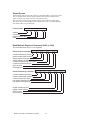
Packet Syntax
Each message packet begins with a one-byte controller address, from 0x01 to 0xF7.
The second byte in the message packet identifies the message command: read
(0x03 or 0x04); write (0x06 or 0x10); or loop back (0x08).
The next n bytes of the message packet contain register addresses and/or data.
The last two bytes in the message packet contain a two-byte Cyclical Redundancy
Checksum (CRC) for error detection.
Packet format:
nn | nn | nnnn…
| nn nn
address
command
registers and/or data
CRC
Read Multiple Registers Command (0x03 or 0x04)
This command returns from 1 to 32 registers.
Packet sent to controller:| nn | 03 | nn nn | 00 nn | nn nn |
controller address (one byte)
read command (0x03 or 0x04)
starting register high byte
starting register low byte
number of registers high byte (0x00)
number of registers low byte
CRC low byte
CRC high byte
Packet returned by controller: | nn | 03 | nn | nn nn … nn nn | nn nn |
controller address (one byte)
read command (0x03 or 0x04)
number of bytes (one byte)
first register data low byte
first register data high byte
…
…
register n data high byte
register n data low byte
CRC low byte
CRC high byte
Watlow Controls Communications Guide
14
Example (988 only): Read register 0 (model number) of the controller at address 1.
Sent:
01 03 00 00 00 01 84 0A
Received: 01 03 02 03 DC B9 2D
Message: 988 (0x03DC).
Example (988 only): Read register 1 and 2 (Process 1 and 2 values) of controller at
address 5.
Sent:
05 03 00 01 00 02 94 4F
Received: 05 03 04 00 64 00 C8 FF BA
Message: 100 (0x0064) and 200 (0x00C8).
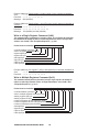
Write to a Single Register Command (0x06)
This command writes a parameter to a single register. The controller will echo back
the command. An attempt to write to a read-only parameter returns an illegal data
address error (0x02). (See “Exception Responses,” pg. 4.9.)
Packet sent to controller:| nn | 06 | nn nn | nn nn | nn nn |
controller address (one byte)
write to a register command (0x06)
register high byte
register low byte
data high byte
data low byte
CRC low byte
CRC high byte
Example (988 only): Set register 7 (SPI) to 200 (0x00C8) on controller at address 9.
Sent:
09 06 00 07 00 C8 38 D5
Received: 09 06 00 07 00 C8 38 D5
Write to Multiple Registers Command (0x10)
This command actually writes a parameter to only a single register. An attempt to
write to a read-only parameter returns an illegal data address error (0x02). (See
“Exception Responses,” pg. 4.9.)
Packet sent to controller:| nn | 10 | nn nn | 00 01 | 02 | nn nn | nn nn |
controller address (one byte)
write to multiple registers command (0x10)
starting register high byte
starting register low byte
number of registers to write high byte (0x00)
number of registers to write low byte (must be 0x01)
number of data bytes (must be 0x02)
data high byte
data low byte
CRC low byte
CRC high byte
Watlow Controls Communications Guide
15
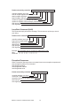
Packet returned by controller: | nn | 10 | nn nn | 00 01 | nn nn |
controller address (one byte)
write to multiple registers command (0x10)
starting register high byte
starting register low byte
number of registers to write high byte (0x00)
number of registers to write low byte (must be 0x01)
CRC low byte
CRC high byte
Loop Back Command (0x08)
This command simply echoes the message. This serves as a quick way to check
your wiring.
Packet sent to controller:| nn | 08 | nn nn | nn nn |
controller address (one byte)
loop back command (0x08)
data high byte
data low byte
CRC low byte
CRC high byte
Example: Run loop back test on controller at address 40 (0x28).
Sent:
28 08 55 66 77 88 31 B7
Received: 28 08 55 66 77 88 31 B7
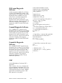
Exception Responses
When a controller cannot process a command it returns an exception response and
sets the high bit (0x80) of the command.
0x01 illegal command
0x02 illegal data address
0x03 illegal data value
Packet returned by controller: | nn | nn | nn | nn nn |
controller address (one byte)
command + 0x80
exception code (0x01 or 0x02 or 0x03)
CRC low byte
CRC high byte
Watlow Controls Communications Guide
16
Messages with the wrong format, timing or CRC are ignored. A read command sent
to an inactive parameter returns 0x0000.
Example: Exception 01 - Command 02 is not supported.
Sent:
01 02 00 01 00 02 A8 0B
Received: 01 82 01 81 60
Example: Exception 02 - The parameter at register 45 (0x002D) is inactive.
Sent:
01 06 00 2D 00 01 D8 C3
Received: 01 86 02 C3 A1
Example: Exception 03 - Cannot write 12,000 (0x2EE0) to register 7, out of range,
illegal data value.
Sent:
01 06 00 07 2E E0 24 23
Received: 01 86 03 02 61
Special Modbus Functions
The following are Modbus registers with special
functions: 24, Disable Non-volatile (system)
Memory; 106, Alarm Status Output 2; 110, Alarm
Status Output 3; 114, Alarm Status Output 4; 200,
Auto-Manual Operation Mode; 311, Clear Input
Errors; 331, Clear Alarms; 332, Silence Alarms.
A "0" indicates an inactive state. Send "1" to the
register to activate the function. It will automatically
reset to "0" when the function is complete. See your
User’s Manual for detail on your specific model.
Watlow Controls Communications Guide
17
manufacturer’s HMI package is unique.
Industrial controllers operate in a harsh,
electrically noisy environment. This can
cause less robust HMIs to work
intermittently or not at all. In addition,
the platform (PC or PLC) which runs the
HMI is subject to failures causing
unpredictable operation of your process.
Watlow has not tested the HMIs listed
with the exception of ANAWIN and
WATLINK. This list is provided as
informational only. Watlow makes no
claims as to the performance or
compatibility with any HMI software
package.
Handling Error Codes
Error codes are divided into two types.
Read error codes and write error codes are
called exception codes. Reading from a
register that does not exist or is currently
disabled will typically respond with a large
out of range value such as -32000, -32001,
or -32002. The Series 988 returns a value
of zero.
Writing to a register that is not supported,
is inactive or out of range will return a
packet with 0x80 added to the command
sent. The byte following this will contain
the value 0x01 for illegal command, 0x02
for illegal address, or 0x03 for illegal data
value. Writing to a read only register will
return an exception code 0x02.
See your user's manual for exact values and
definitions.
Anawin by Watlow Anafaze
334 Westridge Drive
Watsonville, CA 95076
Phone 408-724-3800
http://www.watlow.com
User Responsibility
Users must refrain from altering prompts
that do not appear on the controller’s
front panel or are not included on the
specific model. For example, do not send
an A2LO command to a unit not equipped
with an alarm for output 2.
WATLINK by Watlow Controls
1241 Bundy Blvd
Winona, MN 55987
Phone 507-454-5300
http://www.watlow.com
Most of Watlow controllers contain a
register to disable saving of the current set
point to EEPROM. When using your PC
or PLC to control the set point in the
Watlow controller, the EEPROM may be
prematurely damaged. There is a limit to
the number of times you can store
information in the EPPROM. PCs can
quickly reach this limit if the set point is
continually changed, as in a ramping
controller. Disabling this feature will
prevent this damage.
CONTROLWARE by Controlware
245 Northland Blvd
Cincinnati, OH 45246-3603
Phone 800-776-9704
http://www.controlware.com
Cimplicity by GE Fanuc
Phone 1-800-648-2001
http://www.gefanuc.com
Care must also be taken that the process
can not cause damage to property or
injury to personnel if the wrong
commands are sent due to operator error
or equipment malfunction. Be sure to use
limit devices on the equipment to prevent
system runaway.
Genesis by Iconics
100 Foxborough Blvd
Foxborough, MA 02035
Phone 800-946-9679
http://www.iconics.com
Purchase an HMI package
Not all HMIs are equal in performance. Set
up and operation / function of each
Watlow Controls Communications Guide
18
Interact by CTC
50 W. TechneCenter Drive
Milford, OH 45150
Phone 513-831-2340
http://www.ctcusa.com
Visual Logic Controller by Steeplechase
Software, Inc.
1330 Eisenhower Place
Ann Arbor, MI 48108
Phone 313-975-8100
http://www.steeplechase.com
KEPware MMI by KEPware, Inc.
81 Bridge Street
Yarmouth, ME 04096
Phone 207-846-5881
Wonderware 2000 by Wonderware
Corp.
100 Technology Drive
Irvine, CA 92718
Phone 714-727-3200
http://www.wonderware.com
http://www.kepware.com
LabView by National Instruments
6504 Bridge Point Parkway
Austin, TX 78730-5039
Phone 512-794-0100
http://www.natinst.com
Lookout by National Instruments
6504 Bridge Point Parkway
Austin, TX 78730-5039
Phone 512-794-0100
http://www.natinst.com
Modbus for Windows by Calta
Computer Systems Ltd.
230, 550-71 Ave. SE
Calgary, Alberta Canada T2H 0S6
Phone 403-252-5094
http://www.calta.com
OI-2000 by Software Horizons, Inc.
10 Tower Office Park
Suite 200
Woburn, MA 01801-2120
Phone 617-933-3747
http://www.shorizons.com
SpecView by SpecView, LLC
41 Canyon Green Court
San Ramon, CA 94583
Phone 510-275-0600
http://www.specview.com
Watlow Controls Communications Guide
19
operate in a harsh, electrically noisy
environment. This can cause less robust
converters to work intermittently or not
at all. Watlow has not tested the
converters listed and this list is provided as
informational only. Watlow makes no
claims as to the performance or
compatibility with any converter.
Chapter Five Operator Interface
Panels
Not all Operator Interface Panels are equal
in performance. Programming of each
manufacturer’s panel is unique. Industrial
controllers operate in a harsh, electrically
noisy environment. This can cause less
robust panels to work intermittently or
not at all. Watlow has not tested the
panels listed and this list is provided as
informational only. Watlow makes no
claims as to the performance or
compatibility with any Operator Interface
Panel.
B&B Electronics
707 Dayton Road
PO Box 1040
Ottawa, IL 61350
Phone 815-433-5100
http://www.bb-elec.com
Part # 485OIC for EIA-232 to EIA-422
or EIA-485
EXOR
4740T Interstate Drive
Cincinnati, OH 45246
Phone 513-874-4665
http://www.exor-rd.com
Dataforth Corporation (formerly
supplied by Burr-Brown)
3331 E. Hemisphere Loop
Tucson, AZ 85706
Phone 800-444-7644
Part # LDM422 for EIA-232 to EIA-422
Part # LDM485 for EIA-232 to EIA-485
CTC
50 W. TechneCenter Drive
Milford, OH 45150
Phone 513-831-2340
http://www.ctcusa.com
CMC – Connecticut Microcomputer
Corporation
Watlow Software Tools
Maple Systems
1930 220th Street SE
Suite 101
Bothell, WA 98021
Phone 425-486-4477
http://www.maple-systems.com
920Comm Diagnostic
Software
Watlow has a program available free of
charge called “920COMM.EXE” that is
used with the Series 920 Controller. This
can be downloaded from our BBS at 507452-3958. This is a terminal program that
handles the protocol for you. The
program can be used to determine if your
cables are properly connected and that the
controller is working. This program
supports the ANSI x3.28 and XON/XOFF
protocols.
Advantech
Phone 1-800-800-6889
http://www.advantech-usa.com
Interface Adapters
Not all converters are equal in
performance. Industrial controllers
Watlow Controls Communications Guide
20
#define POLYNOMIAL 0xA001;
unsigned int calc_crc(unsigned char
*start_of_packet, unsigned char
*end_of_packet)
{
unsigned int crc;
unsigned char bit_count;
unsigned char *char_ptr;
922Comm Diagnostic
Software
Another program available free of charge
is called “922COMM.EXE" which is used
with the Series 922 Controller. This can be
downloaded from our BBS at 507-4523958. This is a terminal program that
handles the protocol for you. The
program can be used to determine if your
cables are properly connected and that the
controller is working. This program
supports the ANSI x3.28 and XON/XOFF
protocols.
/* Start at the beginning of the packet */
char_ptr = start_of_packet;
/* Initialize CRC */
crc = 0xffff;
/* Loop through the entire packet */
do{
/* Exclusive-OR the byte with the CRC */
crc ^= (unsigned int)*char_ptr;
/* Loop through all 8 data bits */
bit_count = 0;
do{
Comm4 Diagnostic Software
The “COMM4.EXE” program can be
downloaded free of charge from our BBS at
507-452-3958. This is a terminal program
which handles the protocol for you. The
program can be used to determine if your
cables are properly connected and that the
controller is working. This program
supports the ANSI x3.28 and XON/XOFF
protocols.
/* If the LSB is 1, shift the CRC and XOR
the polynomial mask with the CRC */
if(crc & 0x0001){
crc >>= 1;
crc ^= POLYNOMIAL;
}
Comm5vb Diagnostic
Software
/* If the LSB is 0, shift the CRC only */
else{
crc >>= 1;
}
} while(bit_count++ < 7);
} while(char_ptr++ < end_of_packet);
return(crc);
}
The “COMM5VB.EXE” program can be
downloaded free of charge from our BBS at
507-452-3958. This is a terminal program
that handles the protocol for you. The
program can be used to determine if your
cables are properly connected and that the
controller is working. This program
supports the Modbus, ANSI x3.28 and
XON/XOFF protocols.
CRC
Cyclical Redundancy Checksum (CRC)
Algorithm
This C routine, calc_crc(), calculates the
cyclical redundancy checksum, CRC, for a
string of characters. The CRC is the result
of dividing the string by 0xA001. Modbus
applications calculate the packet’s CRC
then append it to the packet.
Watlow Controls Communications Guide
21
Interface Comparison
Interface
Standard
EIA-232
EIA-423
EIA-422
EIA-485
Maximum
Bus Length
50 feet
4,000 feet
4,000 feet
4,000 feet
Max #
Controllers
1
1
10
32
Cable
Type
3-wire
3-wire
5-wire
3-wire
Summary
As first stated in this article, the steps involved
to communicate are:
1.
2.
3.
Determine how many controllers you
will communicate with
Pick a protocol and interface that
supports the information exchange
Purchase hardware and software to make
this happen.
The number of controlled zones will determine
the number of controllers connected to the PC or
PLC. Pick a protocol that will support this
number. Consider speed and reliability of
communications when picking the protocol. Ask
yourself, how will the devices understand each
other? Pick an interface that will support the
number of devices connected, transmit over the
desired distance and is industrially hardened
(will communicate in electrically noisy
environments). Lastly, purchase an interface,
controllers, PC or PLC and software that will
work together. Software may be written to
accomplish the task if you have the skills and
resources to do so.
Watlow Controls Communications Guide
22
Voltage
Level
3 – 24 v
3 – 12 v
2.0 – 6 v
1.6 – 6 v
Balanced/
Unbalanced
Unbalanced
Unbalanced
Balanced
Balanced
Duplex
Full
Full
Full
Hal
Appendix
Binary
Number based system where only two characters
exist, 0 and 1. Counting is 0, 1, 10, 11...
Glossary
Address
A unique designator for a location of data
or a controller that allows each location or
controller on a single communications bus
to respond to its own message. Similar to
your own residence address.
Bit
Derived from “BInary DigiT ”, a one or zero
condition in the binary system.
Byte
A term referring to eight associated bits of
information, sometimes called a “character”.
ANSI
American National S tandards Institute
CAN Bus
The C ontroller Area Network Bus is a serial
communications protocol that includes software
and hardware. CAN was originally developed by
the German company Robert Bosch for use in the
auto industry to provide a cost-effective
communications bus for in-car electronics.
ANSI x3.28
The American National Standards Institute
developed this communication standard
protocol. This method uses a unique
address for each device. Only the master
can initiate a communications session by
sending an address and then the <ENQ>
character. All other messages must start
with a start of text <STX> and end with an
end of text <ETX> character. The bus is
released to the other device by sending
<EOT> character. Messages are <ACK>
acknowledged or <NAK> negative
acknowledged.
Character
Letter, numeral, punctuation, control figure or
any other symbol contained in a message.
Typically this is encoded in one byte.
Communications
The use of digital computer messages to link
components. (See serial communications and
baud rate)
ASCII (pronounced AS-KEY)
Converter
This device will convert from one hardware
interface to another such as from EIA-232 to EIA485. The converter may be transparent to the
software, which means you do not have to give
any special considerations to software
programming.
American Standard Code for Information
Interchange. A universal standard for
encoding alphanumeric characters into 7
or 8 binary bits.
Asynchronous
Communications where characters can be
transmitted at an unsynchronized point in
time. In other words, it can start and stop
anytime. The time between transmitted
characters may be of varying lengths.
Communication is controlled by “start”
and “stop” bits at the beginning and end of
each character.
CRC
When data is corrupted during transmission, a
method is used to return the data to its correct
value. This can be accomplished through several
methods: parity, checksum and CRC (cyclic
redundancy checksum) are three of these. C yclic
R edundancy C hecksum is an error-checking
mechanism using a polynomial algorithm based
on the content of a message frame at the
transmitter and included in a field appended to
the frame. At the receiver, it is then compared
with the results of the calculation that is
performed by the receiver.
Baud
Unit of signaling speed derived from the number
of events per second (normally bits per second).
Baud rate
The rate of information transfer in serial
communications, measured in bits per second.
Watlow Controls Communications Guide
23
Data
The information that is transferred across
the communications bus. This may be a
setpoint, setup parameter, or any
character. This information is transferred
to an address or register.
EIA
See Electronic Industries Association
EIA-232
Electronic Industries Association
developed this standard hardware interface
to allow one device to talk to another
device in full duplex mode. This method
uses a differential voltage between one
wire and ground. Also called an unbalanced
system since the ground wire carries the
sum of current of all lines. First standard
to gain wide acceptance by manufacturers.
Transmission is limited to about 50 feet.
DB-9
A standardized connector shaped like the
letter “D” when viewed on edge. This
connector has 9 contacts. It is utilized on
most IBM AT compatible PCs as the serial
port.
DB-15
A standardized connector shaped like the
letter “D” when viewed on edge. This
connector has 15 contacts. It is utilized
on most IBM AT compatible PCs as the
game/midi port.
EIA-422
Electronic Industries Association
developed this standard hardware interface
to allow up to 10 devices to be on a bus at
one time. This method uses a differential
voltage between two wires. Also called a
balanced system since each wire carries the
same current values. This has the
advantage of being immune to outside
electrical disturbances.
DB-25
A standardized connector shaped like the
letter “D” when viewed on edge. This
connector has 25 contacts. It is utilized
on most IBM AT compatible PC’s as the
parallel port when the PC end contains
socket contacts. Can also be the serial port
when the PC end contains pin contact.
EIA-423
Electronic Industries Association
developed this standard hardware interface
to allow one device to talk to another
device in full duplex mode. This method
uses a differential voltage between one
wire and ground. Also called an unbalanced
system since the ground wire carries the
sum of current of all lines. This standard is
compatible with EIA-232. The outputs
were beefed up to allow transmission up to
4000 ft.
Decode
This is the reverse of encode. When a
piece of data has information embedded in
it, decode is to extract that information.
Ex. To extract an “A” from 01000001.
DeviceNet
A software protocol / hardware interface
based on CAN. A low cost communication
link that connects industrial devices over a
network. Uses twisted pair wires for the
power and bus. Nodes can be removed or
inserted on the bus without powering down
the network.
EIA-485
Electronic Industries Association
developed this standard hardware interface
to allow up to 32 devices to be on a bus at
one time. This method uses a differential
voltage between two wires. Also called a
balanced system since each wire carries the
same current value. This has the advantage
of being immune to outside electrical
disturbances.
Double Word
Equivalent to two words or four bytes.
This equals 32 bits.
Duplex
The ability to send and receive data at the
same time. “To listen and talk at the same
time.”
Watlow Controls Communications Guide
EIA/TIA -232, -422, -423 and -485
Data communications standards set by the
Electronic Industries Association and
Telecommunications Industry Association.
24
Formerly referred to as RS(Recommended Standard). (See EIA-232,
EIA-422, EIA-423 and EIA-485)
This data is programmed once and cannot
easily be changed as software can.
Full
See Full Duplex.
Electronic Industries Association
(EIA)
An association in the US that establishes
standards for electronics and data
communications
Full Duplex
Full is used to mean the duplex’s full
capability. The ability to send and receive
data at the same time. The same as duplex.
Encode
To embed information into a piece of
data. This is the reverse of decode. Ex.
Let’s let 01000001 stand for an “A”.
GPIB
See IEEE488
Half Duplex
The ability to send or receive data, but not
at the same time. “To listen or talk, but
not both at the same time.”
Error Correction
When an inconsistency is in the data, a
method is used to detect and/or return the
data to its correct value. This can be done
through several methods, parity, checksum
and CRC (cyclic redundancy checksum) are
a three of these.
Handshake (Handshaking)
Exchange of predetermined signals
between two devices establishing a
connection. Using extra wires or software
signals to coordinate communications,
signals can be sent to tell the transmitter
the current status of the other device
receiver. Ex. Are you busy or are you
ready?
Ethernet
A local area network developed by Xerox
in the early 70’s and standardized by
Xerox, Digital Equipment and Intel in
1978. This is a serial communications
method which all devices share the lines.
An address is sent in a packet to talk to a
device on the line. This protocol supports
peer-to-peer communications.
Hex or Hexadecimal
Number based system where sixteen
characters exist, 0 to 9, A to F. Counting
is 0..9,A,B,C..
Even
This term is used with parity. See parity.
HMI
Human to Machine Interface typically
performed in software on a personal
computer. Also called MMI.
Fieldbus
The term fieldbus is a general definition
for an industrial network media that
resides at the machine level and below in a
total network system. The primary
purpose of this network is to interconnect
the machine level and sublevel control
functions and services in a distributive
topology. It is not a particular protocol or
physical connection system. Included in
this generalization definition are standard
protocols of Profibus, Modbus, DeviceNet,
SDS, WorldPIP, and P-Net.
IEEE488
Bus developed by Hewlett-Packard in 1965
as HP-IB. Also referred to as GPIB
(General Purpose Interface Bus). Consist
of 8 data lines and 8 control lines. Bus
length limited to 20.0 meters. Supports 15
devices on the bus at one time.
Logic Level
A voltage measurement system where only
two stable voltage values exist. Ex. 0v and
5V, or -3v and +3v.
Firmware
Instruction or data stored in an IC
(integrated circuit) or on a read only disk.
Watlow Controls Communications Guide
25
Mark
Represents the transmission of data bit
logic 1 (see logic level). Usually this is the
most negative voltage value in serial
communications.
Parallel
Communication using this method,
transfers eight bits or one byte at a time
over eight data wires and one ground wire.
This method is eight times faster than
using serial but utilizes more hardware.
Master
The device on the bus that controls all
communications. Only the master can
initiate conversation.
Parity
A bit is assigned at the beginning of a byte
to stand for parity. When the ‘1’ bits are
counted, the number will be even or odd.
A parity bit is used to ensure that the
answer is always even if even parity or odd
if odd parity. If the receiving end counts
the ‘1’ bits and the sum is not the same
odd or even, an error is generated. Ex.
00010000 has an odd number of 1s. In
even parity, we would set the parity to 1
so we have an even number of bits. In odd
parity, we would set the parity bit to 0 so
we have an odd number of ‘1’ bits. Parity
is used to detect errors caused by noise in
data transmission.
Modbus
A software protocol developed by Gould
Modicon (now AEG) for process control
systems. No hardware interface is defined.
Modbus is accessed on the master/slave
principle, the protocol providing for one
master and up to 247 slaves. Only the
master can initiate a transaction. This is a
half duplex protocol.
MMI
Man to Machine Interface typically
performed in software on a personal
computer. Also called HMI.
PC
Personal Computer, coined by IBM when
it introduced its first IBM PC Jr., which
later became PC, XT, AT, 286, 386, 486,
Pentium, Pro, MMX Pentium, and latest
Pentium II.
Network
When two or more devices share
communications lines, the devices are
“networked”.
Node
A point of interconnection to a network.
Peer to Peer
Two devices that can talk to each other.
Both devices can initiate communications.
This may also be called Master-to-Master
communications.
Noise Immunity
The ability of communications lines to
ignore electrical noise generated in the
communications lines by nearby magnetic
and electrostatic fields.
Profibus
Profibus is actually three buses. Profibus
FMS (Field Message Specification),
Profibus PA (Process Automation), and
Profibus DP (Process Periphery). FMS is a
higher level bus intended to operate with
PLCs, Pcs and higher level nodes. Profibus
DP supports three masters. The masters
then operate with field nodes as master-toslaves. Profibus PA is an intrinsically safe
bus. The protocol is essentially the same
as DP but the electrical / physical
specifications are modified to satisfy low
voltage and current requirements.
Odd
This term is used with parity. See parity.
OSI
Open Systems Interconnection are those
which conform to specifications and
guidelines that are open to all. This allows
equipment from any manufacturer, which
claims to comply with the standard, to be
used interchangeably on the standard
network.
Watlow Controls Communications Guide
26
between data terminal equipment and data
communications equipment for serial
binary data interchange. This is usually for
communications over a short distance (50
feet or less) and to a single device.
Protocol
A set of rules for communication. This
will specify what method to transfer
information, packet size, information
headers and who should talk when. It is
used to coordinate communication
activity.
EIA/TIA-485 (Formerly RS-485) –
An Electronic Industries Association
(EIA)/Telecommunication Industry
Association (TIA) standard for electrical
characteristics of generators and receivers
for use in balanced digital multi-point
systems. This is usually used to
communicate with multiple devices over a
common cable or where distances over 50
feet are required.
Receive
To accept data sent from another device.
The device that receives the data is the
receiver.
Register
An area of memory that provides
temporary storage of digital data.
RJ11
A connector used on most telephones that
has four terminals.
Software
Information of data or program stored in
an easily changeable format. (RAM,
Floppy Disk, Hard Disk)
SDS
Smart Distributed System is a CAN based
device-level control network that can be
scan or event driven, configured as masterslave or peer-to-peer, and can support
devices of varying complexity. . Uses
twisted pair wires for the power and bus.
Space
Represents the transmission of a data bit
logic 0 (see logic level). Usually this is the
most positive voltage value in serial
communications.
Start Bit
A binary bit or logic level that represents
when the serial data information is about
to start (at the beginning of a character or
byte). This voltage level is positive.
Slave
A device that only responds to commands.
This device never starts communication
on it’s own. Only the Master can do this.
(See Master)
Stop Bit
A binary bit or logic level that represents
when the serial data information is
complete (at the end of a character or
byte). This voltage level is negative.
SCADA
Supervisory Control and Data Acquisition
Serial
To process something in order. First item,
second item, etc.
Synchronous
When data is transmitted on a data line
and a clock signal is used on another line
to determine when to check the data line
for a logic level. This clock is said to
“synchronize” the data.
Serial Communications
A method of transmitting information
between devices by sending all bits serially
(see serial) over a single communication
channel.
TCP/IP
Transmission Control Protocol/Internet
Protocol is a software protocol used to
send and receive data between different
computer systems. Standard protocol used
on the Internet.
EIA/TIA-232
(Formerly RS-232) An Electronic Industries Association
(EIA)/Telecommunication Industry
Association (TIA) standard for interface
Watlow Controls Communications Guide
27
Transmit
To send data from one device to another.
The device that sends the data is the
transmitter.
Word
Two bytes make a word. This contains 16
bits.
XON/XOFF
A software protocol that controls the flow
of serial information. Sending an XON
tells the transmitter to start sending
information. An XOFF tells the
transmitter to stop sending until the
receiver has processed the current
information. XOFF = DC3 = Control S =
hex 11, XON = DC1 = Control Q = hex
13.
Disclaimer of Warranty
This is a general overview and statement
of the safety-related need for and
methods of applying "data comunications
for temperature processes." Because of
the diversity of conditions and hazards
under which control products may be
applied, and because of the differences in
components and methods of their
installation, no representation or warranty
of any kind, express or implied, is
hereby made, that the data comunications
discussed and presented herein will be
effective in any particular application or
set of circumstances, or that additional or different precautions will not be
reasonably necessary for a particular application. We will be pleased to
consult with you regarding a specific
application upon request.
Trademark Information
Watlow®, Gordon®, Anafaze®,
ANASOFT®, ANAWIN®, MICRODIN
are trademarks of Watlow Electric
Manufacturing Company.
Modbus™ is a trademark of AEG
Schneider Automation.
Windows® and Microsoft® are trademarks
of the Microsoft Corporation.
Watlow Controls Communications Guide
28
Index
A
922 Comm Diagnostic 21
Appendix 23
ASCII Chart 6
ASCII 5
Audience 4
B
Baud Rate 8
Biasing of Buses 9
Bits and Bytes 5
C
Character Format 5
Comm4 Diagnostic Software 21
Comm5vb Diagnostic Software 21
Computer Languages 8
Controller Comparison Summery 22
Convention 4
CRC 21
D
Disclaimer of Warranty 28
E
Elements of Machine to Machine
Comm. 5
G
Getting Started 4
Glossary 23
I
Interface Adapters 20
Interface Comparison 22
Interface Converters 10
Interface Standards 9
M
Media 4
P
Parity Bits 7
Protocols 10
Purchase an HMI package 18
Purpose 4
S
Serial Communication 7
Start and Stop Bits 8
Syntax 8
W
Watlow Software Tools 20
Wiring 9
Write Your Own (HMI) 12
Watlow Controls Communications Guide
29
How to Reach Us
Contact
Your Authorized Watlow Distributor:
Quality and
Mission
Statement:
Watlow Controls will be
the world’s best
supplier of industrial
temperature control
products, services and
systems by exceeding
our customers’,
employees’ and
shareholders’
expectations.
• Phone: (507) 454-5300.
• Fax: (507) 452-4507.
• For technical support, ask for an Applications Engineer.
• To place an order, ask for Customer Service.
• To discuss a custom option, ask for a Product Manager.
Warranty
Most Watlow Controls are warranted to be free of defects in material and workmanship for 36 months after delivery to the first purchaser for use, providing
that the units have not been misapplied. Since Watlow has no control over their
use, and sometimes misuse, we cannot guarantee against failure. Watlow's
obligations hereunder, at Watlow's option, are limited to replacement, repair or
refund of purchase price, and parts which upon examination prove to be defective within the warranty period specified. This warranty does not apply to damage resulting from transportation, alteration, misuse or abuse.
Returns
• Call or fax Customer Service for a Return Material Authorization (RMA)
number before returning a controller.
• Put the RMA number on the shipping label, and also on a written description of the problem.
• A restocking charge of 20% of the net price is charged for all standard units
returned to stock.
Watlow Controls Communications Guide
Watlow Controls, 1241 Bundy Blvd., P.O. Box 5580, Winona, Minnesota USA 55987-5580,
Phone: (507) 454-5300, Fax: (507) 452-4507