1
N8100-1235F/1236F/1321F/1322F
1287F/1288F/1352F
N8100-1237F/1238F/1323F/1324F
1290F/1291F/1293F
NEC Express5800/120Eh
User's Guide
3rd Edition
5-2007
ONL-4152dN-120Eh-100-99-0704
PROPRIETARY NOTICE AND LIABILITY DISCLAIMER
The information disclosed in this document, including all designs and related materials, is the
valuable property of NEC Corporation (NEC) and /or its licensors. NEC and/or its licensors, as
appropriate, reserve all patent, copyright and other proprietary rights to this document, including all
design, manufacturing, reproduction, use, and sales rights thereto, except to the extent said rights are
expressly granted to others.
The NEC product(s) discussed in this document are warranted in accordance with the terms of the
Warranty Statement accompanying each product. However, actual performance of each such
product is dependent upon factors such as system configuration, customer data, and operator control.
Since implementation by customers of each product may vary, the suitability of specific product
configurations and applications must be determined by the customer and is not warranted by NEC.
To allow for design and specification improvements, the information in this document is subject to
change at any time, without notice. Reproduction of this document or portions thereof without prior
written approval of NEC is prohibited.
First Printing, July 2006
Revised, May 2007
Copyright 2006, 2007
NEC Corporation
7-1 Shiba 5-Chome, Minato-Ku
Tokyo 108-8001, Japan
All Rights Reserved
Printed in Japan
Keep this manual at hand for quick reference at anytime necessary.
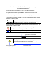
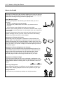
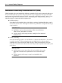
SAFETY INDICATIONS
Follow the instructions in this manual for your safety to use the NEC Express server.
Your server contains components with possible danger, hazards that may cause by ignoring
warnings, and preventive actions against such hazards.
Server components with possible danger are indicated with a warning label placed on or around them
as well as described in this manual.
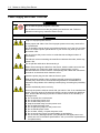
In this manual or warning labels, "WARNING" or "CAUTION" is used to indicate a degree of danger.
These terms are defined as follows:
WARNING
CAUTION
Indicates the presence of a hazard that may result in death or serious
personal injury if the instruction is ignored.
Indicates the presence of a hazard that may cause minor personal injury,
including burns, or property damage if the instruction is ignored.
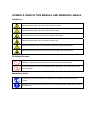
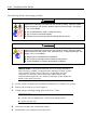
Precautions and notices against hazards are presented with one of the following three symbols. The
individual symbols are defined as follows:
This symbol indicates the presence of a hazard if the instruction is ignored.
An image in the symbol illustrates the hazard type. (Attention)
This symbol indicates prohibited actions. An image in the symbol illustrates a particular
prohibited action. (Prohibited Action)
This symbol indicates mandatory actions. An image in the symbol illustrates a
mandatory action to avoid a particular hazard. (Mandatory Action)
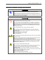
(Example)
Symbol to draw attention
Term indicating a degree of danger
CAUTION
High temperature.
Immediately after the server is powered off, its internal components such as
hard disk drives are very hot. Leave the server until its internal components
fully cool down before installing/removing any component.
Symbol indicating a prohibited
action (may not always be
indicated)
Description of a danger
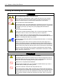
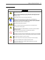
SYMBOLS USED IN THIS MANUAL AND WARNING LABELS
Attentions
Indicates that improper use may cause an electric shock.
Indicates that improper use may cause personal injury.
Indicates that improper use may cause fingers to be caught.
Indicates that improper use may cause fumes or fire.
Indicates a general notice or warning that cannot be specifically identified.
Indicates that improper use may cause loss of eyesight due to laser beam.
Prohibited Actions
Indicates a general prohibited action that cannot be specifically identified.
Do not disassemble, repair, or modify the server. Otherwise, an electric shock or fire
may be caused.
Mandatory Action
Unplug the power cord of the server. Otherwise, an electric shock or fire may be
caused.
Indicates a mandatory action that cannot be specifically identified. Make sure to follow
the instruction.
NOTE: This equipment has been tested and found to comply with the limits for a Class B digital
device, pursuant to Part 15 of the FCC Rules. These limits are designed to provide reasonable
protection against harmful interference in a residential installation. This equipment generates, uses
and can radiate radio frequency energy and, if not installed and used in accordance with the
instructions, may cause harmful interference to radio communications. However, there is no
guarantee that interference will not occur in a particular installation. If this equipment does cause
harmful interference to radio or television reception, which can be determined by turning the
equipment off and on, the user is encouraged to try to correct the interference by one or more of the
following measures:
• Reorient or relocate the receiving antenna.
• Increase the separation between the equipment and receiver.
• Connect the equipment into an outlet on a circuit different from that to which the receiver is
connected.
• Consult the dealer or an experienced radio/TV technician for help
Momentary voltage drop prevention:
This product may be affected by a momentary voltage drop caused by lightning. To prevent a
momentary voltage drop, an AC uninterruptible power supply (UPS) unit should be used.
Trademarks
NEC ESMPRO, NEC EXPRESSBUILDER, and NEC EXPRESSSCOPE are trademarks of NEC Corporation.
Microsoft, Windows, Windows Server, Windows NT, and MS-DOS are registered trademarks or trademarks of
Microsoft Corporation in the United States and other countries.
Intel and Pentium are registered trademarks of Intel Corporation.
LSI Logic, LSI Logic Logo Design, MegaRAID, MegaRAID Storage Manager, and Power Console Plus are
registered trademarks or trademarks of LSI Corporation.
Datalight is a registered trademark of Datalight, Inc.
ROM-DOS is a trademark of Datalight, Inc.
Novell and NetWare are registered trademarks of Novell, Inc. of the United States.
AT is a registered trademark of International Business Machines Corporation in the United States and other
countries.
Adobe, Adobe logo, and Acrobat are trademarks of Adobe Systems Incorporated.
DLT and DLTtape are trademarks of Quantum Corporation of the United States.
All other product, brand, or trade names used in this publication are the trademarks or registered trademarks of
their respective trademark owners.
Windows Server 2003 x64 Editions stands for Microsoft® Windows® Server 2003 R2, Standard x64 Edition
Operating system and Microsoft® Windows® Server 2003 R2, Enterprise x64 Edition operating system, or
Microsoft® Windows® Server 2003, Standard x64 Edition operating system and Microsoft® Windows®
Server 2003, Enterprise x64 Edition operating system. Windows Server 2003 stands for Microsoft®
Windows® Server 2003 R2, Standard Edition operating system and Microsoft® Windows® Server 2003
R2, Enterprise Edition operating system, or Microsoft® Windows® Server 2003, Standard Edition operating
system and Microsoft® Windows® Server 2003, Enterprise Edition operating system.
Windows Vista stands for Microsoft® Windows Vista Business operating system.
Windows XP x64 Edition stands for Microsoft® Windows® XP Professional x64 Edition operating system.
Windows XP stands for Microsoft® Windows® XP Home Edition operating system and Microsoft®
Windows® XP Professional operating system. Windows 2000 stands for Microsoft® Windows® 2000 Server
operating system and Microsoft® Windows® 2000 Advanced Server operating system, and Microsoft®
Windows® 2000 Professional operating system. Windows NT stands for Microsoft® Windows NT® Server
network operating system version 3.51/4.0 and Microsoft® Windows NT® Workstation operating system
version 3.51/4.0. Windows Me stands for Microsoft® Windows® Millennium Edition operating system.
Windows 98 stands for Microsoft® Windows®98 operating system. Windows 95 stands for Microsoft®
Windows®95 operating system.
Notes:
(1) No part of this manual may be reproduced in any form without the prior written permission of
NEC Corporation.
(2) The contents of this manual may be revised without prior notice.
(3) The contents of this manual shall not be copied or altered without the prior written permission
of NEC Corporation.
(4) All efforts have been made to ensure the accuracy of all information in this manual. If you
notice any part unclear, incorrect, or omitted in this manual, contact the service representative
where you purchased this product.
(5) NEC assumes no liability arising from the use of this product, nor any liability for incidental or
consequential damages arising from the use of this manual regardless of Item (4).
i
PREFACE
Congratulations on the purchase of your NEC Express server.
Purchase of this server is your assurance of receiving state-of-the-art, high quality hardware to meet
your needs, both now and in the future.
Read this User's Guide thoroughly to fully understand handling of the NEC Express server and
appreciate its functions to the maximum extent.
ii
ABOUT THIS USER'S GUIDE
This manual is a guide for proper setup and use of your server.
This manual also covers useful procedures for dealing with difficulties and problems that may arise
during setup or operation of your server.
Keep this manual for future use.
The following describes how to proceed with this manual.
How to Use This Manual
To aid you in finding information quickly, this manual contains the following information:
Chapter 1 Notes on Using Your Server
includes information that needs attention to use the server. Make sure to read this chapter before
setting up and using the server. It also includes requirements and advisory information for
transfer and disposal of the server.
Chapter 2 General Description
includes information necessary to use the server, such as names and functions of its
components, handling of the floppy disk and DVD-ROM drives.
Chapter 3 Setting Up Your Server
tells you how to select a site, unpack the system, make cable connections, and power on your
system.
Chapter 4 Configuring Your Server
tells you how to configure the system and provides instructions for running the BIOS SETUP
Utility and the RAID configuration utility, which is used to configure RAID drives in your system.
This chapter also provides information on mother board jumper settings.
Chapter 5 Installing the Operating System with Express Setup
describes how to install the operating system.
Chapter 6 Installing and Using Utilities
describes how to install the utilities for the server. It also includes a description on using the
attached "NEC EXPRESSBUILDER" CD-ROM.
Chapter 7 Maintenance
provides you with all the information necessary to maintain successful operation of the server.
This chapter also includes a description on relocating and storing the server.
Chapter 8 Troubleshooting
contains helpful information for solving problems that might occur with your system.
Chapter 9 Upgrading Your Server
provides you with instructions for upgrading your system with an additional processor, optional
memory, optional add-in cards, hard disk drives, peripheral devices, and power supply.
Chapter 10 Internal Cabling Diagram
includes cabling information for the SAS/SATA2 controller, 5.25-inch device, and the power
supply.
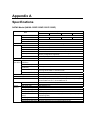
Appendix A Specification
provides specifications for your server.
iii
Appendix B Other Precautions
provides supplementary notes on using the server.
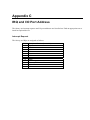
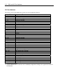
Appendix C IRQ and I/O Port Address
provides a list of factory-set IRQs and I/O port addresses assigned.
Appendix D Installing Windows Server 2003 x64 Editions
describes how to install Microsoft Windows Server 2003 x64 Editions without using Express
Setup. Using the Express Setup tool is recommended for installing Windows Server 2003 x64
Editions. See Chapter 5 for details.
Appendix E Installing Windows Server 2003
describes how to install Microsoft Windows Server 2003 without using Express Setup. Using the
Express Setup tool is recommended for installing Windows Server 2003. See Chapter 5 for
details.
Appendix F Product Configuration Record Table
provides a table to be filled with your server configuration.
Text Conventions
The following conventions are used throughout this manual. For safety symbols, see "SAFETY
INDICATIONS" provided earlier.
IMPORTANT:
Items that are mandatory or require attention when using the server
NOTE:
Helpful and convenient piece of information
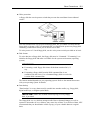
IN THE PACKAGE
The carton contains various accessories, as well as the server itself. See the packing list to make
sure that you have everything and that individual components are not damaged. If you find any
component missing or damaged, contact your service representative.
Store the provided accessories in a designated place for your convenience. You will need
them to install an optional device or troubleshoot your server, as well as to set it up.
Make a backup copy of each provided floppy disk, if any. Store the original disk as the
master disk in a designated place, and use its copy.
Improper use of any provided CD-ROM may alter your system environment. If you find
anything unclear, immediately ask your service representative for help.
iv
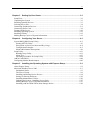
CONTENTS
Preface ..............................................................................................................................................i
About This User's Guide..................................................................................................................ii
In the Package.................................................................................................................................iii
Chapter 1 Notes on Using Your Server........................................................................ 1-1
Warning Labels.............................................................................................................................1-2
Safety Notes..................................................................................................................................1-3
General .....................................................................................................................................1-3
Power Supply and Power Cord Use .........................................................................................1-4
Installation, Relocation, Storage, and Connection....................................................................1-5
Cleaning and Working with Internal Devices...........................................................................1-6
During Operation .....................................................................................................................1-7
For Proper Operation ....................................................................................................................1-8
Transfer to Third Party .................................................................................................................1-9
Disposal and Consumables .........................................................................................................1-10
User Support...............................................................................................................................1-11
Chapter 2 General Description ..................................................................................... 2-1
Overview ......................................................................................................................................2-2
System Chassis .............................................................................................................................2-3
Front View................................................................................................................................2-3
Rear View.................................................................................................................................2-6
Internal View ............................................................................................................................2-8
Mother Board..............................................................................................................................2-10
Standard Features .......................................................................................................................2-12
Power Supply .........................................................................................................................2-13
Peripheral Bays ......................................................................................................................2-13
Remote Power-On Feature (Wake On LAN)..........................................................................2-13
AC LINK Feature...................................................................................................................2-13
Security ..................................................................................................................................2-13
NEC EXPRESSBUILDER ....................................................................................................2-14
NEC ESMPRO.......................................................................................................................2-14
Off-line Maintenance Utility ..................................................................................................2-15
System Diagnostic Utility ......................................................................................................2-15
Remote Management..............................................................................................................2-15
Using Your Server.......................................................................................................................2-16
POWER Switch......................................................................................................................2-16
Power Off ...............................................................................................................................2-20
SLEEP Switch ........................................................................................................................2-20
DVD-ROM Drive...................................................................................................................2-21
v
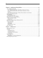
Chapter 3 Setting Up Your Server ................................................................................ 3-1
Setup Flow....................................................................................................................................3-2
Unpacking the System ..................................................................................................................3-3
Installing Optional Devices ..........................................................................................................3-3
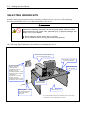
Selecting Server Site.....................................................................................................................3-4
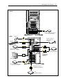
Connecting Peripheral Devices.....................................................................................................3-6
Connecting Power Cord................................................................................................................3-8
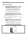
Turning On the Server ................................................................................................................3-10
Installing Operating System .......................................................................................................3-12
Installing Utilities .......................................................................................................................3-12
Making Backup Copies of System Information..........................................................................3-12
Chapter 4 Configuring Your Server.............................................................................. 4-1
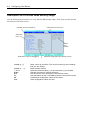
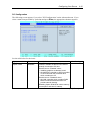
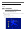
System BIOS (BIOS Setup Utility) ..............................................................................................4-2
Starting SETUP Utility.............................................................................................................4-3
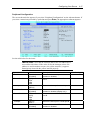
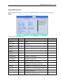
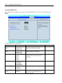
Description on On-Screen Items and Key Usage .....................................................................4-4
Configuration Examples...........................................................................................................4-5
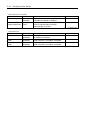
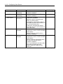
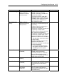
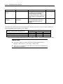
Menu and Parameter Descriptions ...........................................................................................4-9
Setup Utility................................................................................................................................4-31
Running Setup Utility.............................................................................................................4-31
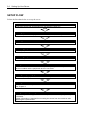
Menu Tree ..............................................................................................................................4-33
Operating Procedures for Setup Utility ..................................................................................4-34
Add-in Card's BIOS....................................................................................................................4-44
Configuring Mother Board Jumpers ...........................................................................................4-45
Chapter 5 Installing the Operating System with Express Setup............................... 5-1
About Express Setup ....................................................................................................................5-2
Microsoft Windows Server 2003 ..................................................................................................5-3
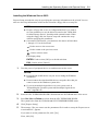
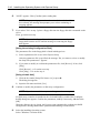
Installation Notice ....................................................................................................................5-3
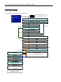
The Flow of Setup ....................................................................................................................5-8
Installing and Setting Device Drivers.....................................................................................5-14
Setting for Solving Problems .................................................................................................5-22
Installing Maintenance Utilities .............................................................................................5-26
Updating the System – Installing Service Pack –...................................................................5-27
Making Backup Copies of System Information .....................................................................5-27
Installing with the OEM-FD for Mass Storage Device ..........................................................5-28
vi
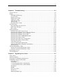
Chapter 6 Installing and Using Utilities ....................................................................... 6-1
NEC EXPRESSBUILDER...........................................................................................................6-2
NEC EXPRESSBUILDER for DOS-Based with Local Console.............................................6-4
NEC EXPRESSBUILDER for DOS-based with Remote Console ..........................................6-9
Starting ...................................................................................................................................6-10
NEC EXPRESSBUILDER for Windows-Based (Master Control Menu)..............................6-13
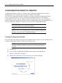
Configuration Diskette Creator...................................................................................................6-14
NEC ESMPRO ...........................................................................................................................6-18
Functions and Features...........................................................................................................6-18
Web-based Promise Array Manager ...........................................................................................6-19
MegaRAID Storage Manager (Server) .......................................................................................6-19
Setup with Express Setup .......................................................................................................6-19
Manual Setup .........................................................................................................................6-19
MegaRAID Storage Manager (Management PC).......................................................................6-19
Power Console Plus ....................................................................................................................6-20
Major Functions .....................................................................................................................6-20
Components............................................................................................................................6-20
Server Setup ...........................................................................................................................6-22
Management PC Setup ...........................................................................................................6-23
NEC DianaScope........................................................................................................................6-24
Chapter 7 Maintenance.................................................................................................. 7-1
Making Backup Copies ................................................................................................................7-1
Cleaning........................................................................................................................................7-2
Cleaning the Server ..................................................................................................................7-3
Cleaning the Interior.................................................................................................................7-4
Cleaning the Keyboard/Mouse.................................................................................................7-5
Cleaning Disc ...........................................................................................................................7-6
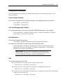
System Diagnostics.......................................................................................................................7-7
Test Items .................................................................................................................................7-7
Startup and Exit of System Diagnostics ...................................................................................7-8
Relocating/Storing The Server....................................................................................................7-11
vii
Chapter 8 Troubleshooting ........................................................................................... 8-1
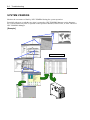
System Viewers ............................................................................................................................8-2
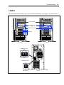
Lamps ...........................................................................................................................................8-3
POWER/SLEEP Lamp.............................................................................................................8-4
Access Lamps...........................................................................................................................8-4
DISK Access Lamp ..................................................................................................................8-4
LINK/ACT Lamp .....................................................................................................................8-4
1000/100/10 Lamp ...................................................................................................................8-5
100/10 Lamp ............................................................................................................................8-5
Hard Disk Drive Lamp .............................................................................................................8-5
Error Messages .............................................................................................................................8-7
Error Messages after Power-on ................................................................................................8-7
POST Error Messages ..............................................................................................................8-8
Beep Codes.............................................................................................................................8-11
Solving Problems........................................................................................................................8-12
Problems with NEC Express Server.......................................................................................8-12
Problems with Windows Server 2003 x64 Editions ...............................................................8-16
Problems with Windows Server 2003 R2...............................................................................8-17
Problems with Windows Server 2003 ....................................................................................8-18
Problems with NEC EXPRESSBUILDER ............................................................................8-21
Problems with Express Setup .................................................................................................8-22
Problems with Disk Array Configuration...............................................................................8-25
Problems with Master Control Menu .....................................................................................8-26
Collecting Event Log .............................................................................................................8-26
Collect Configuration Information .........................................................................................8-27
Collecting Dr. Watson Diagnostic Information ......................................................................8-27
Memory Dump .......................................................................................................................8-27
Off-line Maintenance Utility ......................................................................................................8-28
Starting the Off-line Maintenance Utility...............................................................................8-28
Features of Off-line Maintenance Utility ...............................................................................8-29
Resetting the Server....................................................................................................................8-30
Forced Shutdown........................................................................................................................8-30
Chapter 9 Upgrading Your Server ................................................................................ 9-1
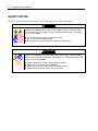
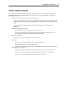
Safety Notes..................................................................................................................................9-2
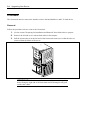
Static Precautions .........................................................................................................................9-3
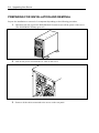
Preparing for Installation and Removal ........................................................................................9-4
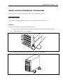
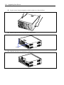
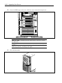
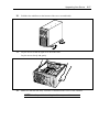
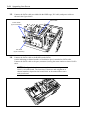
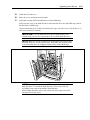
Installation or Removal Procedure ...............................................................................................9-5
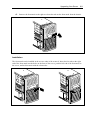
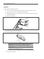
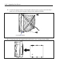
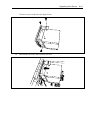
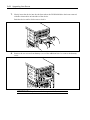
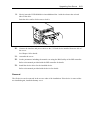
Left Side Cover ........................................................................................................................9-5
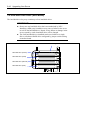
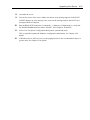
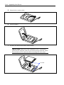
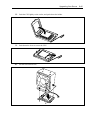
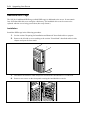
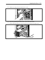
Front Mask ...............................................................................................................................9-8
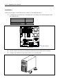
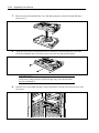
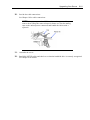
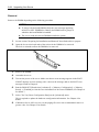
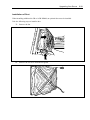
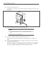
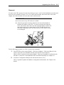
3.5-inch Hard Disk Drive (SAS Model).................................................................................9-10
3.5-inch Hard Disk Drive (SATA Model)...............................................................................9-17
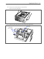
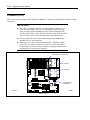
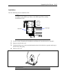
PCI Board...............................................................................................................................9-23
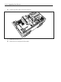
DIMM ....................................................................................................................................9-33
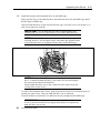
Processor (CPU).....................................................................................................................9-42
File Device .............................................................................................................................9-48
Additional HDD Cage............................................................................................................9-54
viii
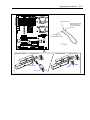
Chapter 10 Internal Cabling Diagrams....................................................................... 10-1
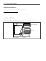
Interface Cables ..........................................................................................................................10-2
Addition of Hard Disk Drive..................................................................................................10-2
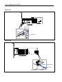
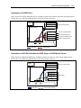
Connection of Disk Array Controller N8103-91 (SAS) .........................................................10-4
Connection of Disk Array Controller N8103-101 (SATA2)...................................................10-6
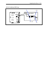
Connection of 5.25-inch Device.............................................................................................10-9
Power Cables ............................................................................................................................10-11
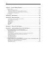
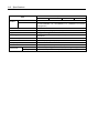
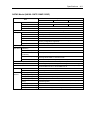
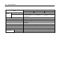
Appendix A
Specifications............................................................................................A-1
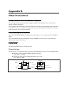
Appendix B
Other Precautions.....................................................................................B-1
Transfer Rate of the On-board LAN Controller ...................................................................... B-1
Server Management Software ................................................................................................. B-1
Floppy Disk............................................................................................................................. B-1
DVD/CD-ROM ....................................................................................................................... B-4
Tape Media.............................................................................................................................. B-4
Keyboard ................................................................................................................................. B-5
Mouse...................................................................................................................................... B-6
Appendix C
IRQ and I/O Port Address.........................................................................C-1
Appendix D Installing Windows Server 2003 x64 Editions........................................D-1
Before Installing Windows Server 2003 x64 Editions.................................................................D-1
Optional Board Supported by NEC EXPRESSBUILDER......................................................D-1
Installing Service Pack ............................................................................................................D-2
Updating System .....................................................................................................................D-2
Re-installing to the Hard Disk which has been upgraded to Dynamic Disk ...........................D-2
Manual Installation when N8103-80F Keeps Connection.......................................................D-2
Mounting MO Device .............................................................................................................D-2
About Removable Media ........................................................................................................D-2
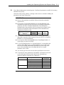
Creating Partition Size ............................................................................................................D-3
Installing Windows Server 2003 x64 Editions.............................................................................D-4
Creating "Windows Server 2003 x64 Edition OEM-DISK for NEC EXPRESSBUILDER"..D-4
Windows Server 2003 x64 Editions Clean Installation ...........................................................D-6
Reinstallation to Multiple Logical Drives ...............................................................................D-8
Updating the System .............................................................................................................D-10
ix
Driver Installation and Advanced Settings ................................................................................ D-11
PROSet.................................................................................................................................. D-11
Adapter Fault Tolerance (AFT)/Adaptive Load Balancing (ALB)........................................D-12
Network Driver .....................................................................................................................D-13
Re-install the Network Driver ...............................................................................................D-14
Re-install the Optional Network Board Driver......................................................................D-15
Installation of the Optional Network Board Driver...............................................................D-15
Graphics Accelerator Driver..................................................................................................D-16
Optional Network Board Driver............................................................................................D-18
Installing SCSI Controller Driver (N8103-75)......................................................................D-19
Installing SCSI Controller Driver (N8103-95)......................................................................D-19
Installing Disk Array Controller Driver (N8103-80F) ..........................................................D-19
About Windows Activation ...................................................................................................D-20
Setting for Collecting Memory Dump (Debug Information).....................................................D-22
Appendix E Installing Windows Server 2003 .............................................................. E-1
Before Installing Windows Server 2003 ...................................................................................... E-1
Optional Board Supported by NEC EXPRESSBUILDER...................................................... E-1
Installing Service Pack ............................................................................................................ E-2
Updating System ..................................................................................................................... E-2
Re-installing to the Hard Disk which has been upgraded to Dynamic Disk ........................... E-2
Manual Installation when N8103-80F Keeps Connection....................................................... E-2
Mounting MO Device ............................................................................................................. E-2
About Removable Media ........................................................................................................ E-2
Application of Service Pack .................................................................................................... E-2
Creating Partition Size ............................................................................................................ E-3
Installing Windows Server 2003.................................................................................................. E-4
Creating "Windows Server 2003 OEM-DISK for NEC EXPRESSBUILDER" ..................... E-4
Windows Server 2003 Clean Installation ................................................................................ E-6
Reinstallation to Multiple Logical Drives ............................................................................... E-9
Re-installing the Operation System if Multiple Logical Drives Exist................................... E-11
Updating the System ............................................................................................................. E-12
Driver Installation and Advanced Settings ................................................................................ E-13
PROSet.................................................................................................................................. E-13
Network Driver ..................................................................................................................... E-14
Re-install the Network Driver ............................................................................................... E-15
Graphics Accelerator Driver.................................................................................................. E-16
Installing SCSI Controller Driver (N8103-75/95)................................................................. E-18
Installing Disk Array Controller Driver (N8103-80F) .......................................................... E-18
Notes of N8103-75 ................................................................................................................ E-19
About Windows Activation ................................................................................................... E-20
Available Switch Options for Windows Server 2003 Boot.ini File ....................................... E-22
Setting for Collecting Memory Dump (Debug Information)..................................................... E-23
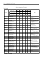
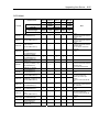
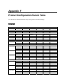
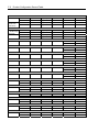
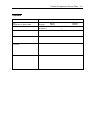
Appendix F Product Configuration Record Table ...................................................... F-1
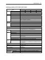
Hardware ................................................................................................................................. F-1
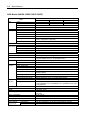
Software .................................................................................................................................. F-3
x
(This page is intentionally left blank.)
Chapter 1
Notes on Using Your Server
This chapter includes information necessary for proper and safe operation of your server.
1-2 Notes on Using Your Server
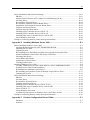
WARNING LABELS
The warning label is attached to components with possible danger or their vicinity in your server to
inform the user that a hazardous situation may arise when operating the server. (Do not intentionally
remove or damage any of the labels.)
If you find any labels totally/partially removed or illegible due to damage, contact your service
representative.
Notes on Using Your Server 1-3
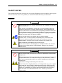
SAFETY NOTES
This section provides notes on using your server safely. Read this section carefully to ensure proper
and safe use of the server. For symbols, see "SAFETY INDICATIONS" provided earlier.
General
WARNING
Do not use the server for services where critical high availability may directly
affect human lives.
Your server is not intended to be used with or control facilities or devices
concerning human lives, including medical devices, nuclear facilities and
devices, aeronautics and space devices, transportation facilities and devices;
and facilities and devices requiring high reliability. NEC assumes no liability
for any accident resulting in personal injury, death, or property damage if the
server has been used in the above conditions.
Do not use the server if any smoke, odor, or noise is present.
If smoke, odor, or noise is present, immediately turn off the server and
disconnect the power plug from the outlet, then contact your service
representative. Using the server in such conditions may cause a fire.
Keep needles or metal objects away from the server.
Do not insert needles or metal objects into ventilation holes in the server or
openings in the floppy disk or DVD-ROM drive. Doing so may cause an
electric shock.
CAUTION
Do not access inside your server for a service or replacement of the internal
components.
The service representative can only install or remove the internal components
and optional devices. To avoid personal injury or electrical shock, contact
your service representative when your need to install/remove the internal
components.
Keep water or foreign matter away from the server.
Do not let any form of liquid (water etc.) or foreign matter (e.g., pins or paper
clips) enter the server. Failure to follow this warning may cause an electric
shock, a fire, or a failure of the server. When such things accidentally enter
the server, immediately turn off the power and disconnect the power plug
from the outlet. Do not disassemble the server. Contact your service
representative.
1-4 Notes on Using Your Server
Power Supply and Power Cord Use
WARNING
Do not hold the power plug with a wet hand.
Do not disconnect/connect the plug while your hands are wet. Failure to
follow this warning may cause an electric shock.
CAUTION
Plug in to a proper power source.
Use a proper wall outlet. Use of an improper power source may cause a fire
or a power leak.
Do not install the server where you need an extension cord. Use of a cord that
does not meet the power specifications of your server may heat up the cord
and cause a fire.
Do not connect the power cord to an outlet that has an illegal number of
connections.
The electric current exceeding the rated flow overheats the outlet, which may
cause a fire.
Do not pull the cable when disconnecting it.
When disconnecting the cable from the device, hold the cable connector and
pull it straight out. Pulling the cable out by the cable portion or giving
mechanical stress to the connector could damage the cables and connectors
to result in an electrical shock hazard or a fire.
Insert the power plug into the outlet as far as it goes.
Heat generation resulting from a halfway inserted power plug (imperfect
contact) may cause a fire. Heat will also be generated if condensation is
formed on dusty blades of the halfway inserted plug, increasing the possibility
of fire.
Use the authorized power cord only.
Use only the power cord that comes with your server. Use of an unauthorized
power cord may cause a fire when the electric current exceeds the rated flow.
Also, observe the following to prevent an electric shock or fire caused by a
damaged cord.
■ Do not stretch the cord harness.
■ Do not pinch the power cord.
■ Do not bend the power cord.
■ Keep chemicals away from the power cord.
■ Do not twist the power cord.
■ Do not place any object on the power cord.
■ Do not bundle power cords.
■ Do not alter, modify, or repair the power cord.
■ Do not secure the power cord with staples or equivalents.
■ Do not use any damaged power cord. (Replace a damaged power cord
with a new one of the same specifications. Ask your service representative
for replacement.)
Notes on Using Your Server 1-5
Installation, Relocation, Storage, and Connection
WARNING
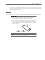
Disconnect the power cord(s) before installing or removing the server.
Make sure to power off the server and disconnect the power cord(s) from a
power outlet before installing/removing the server. All voltage is removed only
when the power cords are unplugged.
CAUTION
Never attempt to lift the server only by yourself.
Your server weighs max 20 kg (depending on its hardware configuration).
Carrying the server only by yourself may strain your back. Hold the server
firmly by its bottom with at least two or more people. Do not hold the front
mask to lift the server. The front mask may be disengaged from the server,
causing personal injury.
Do not install the server in any place other than specified.
Do not install the server in the following places or any place other than
specified in this manual. Failure to follow this instruction may cause a fire.
■ a dusty place
■ a humid place such as near a boiler
■ a place exposed to direct sunlight
■ an unstable place
Do not connect any interface cable with the power cord of the server plugged
to a power source.
Make sure to power off the server and unplug the power cord from a power
outlet before installing/removing any optional internal device or
connecting/disconnecting any interface cable to/from the server. If the server
is off-powered but its power cord is plugged to a power source, touching an
internal device, cable, or connector may cause an electric shock or a fire
resulted from a short circuit.
Do not use any unauthorized interface cable.
Use only interface cables provided by NEC and locate a proper device and
connector before connecting a cable. Using an authorized cable or
connecting a cable to an improper destination may cause a short circuit,
resulting in a fire.
Also, observe the following notes on using and connecting an interface cable.
■ Do not use any damaged cable connector.
■ Do not step on the cable.
■ Do not place any object on the cable.
■ Do not use the server with loose cable connections.
1-6 Notes on Using Your Server
Cleaning and Working with Internal Devices
WARNING
Do not disassemble, repair, or alter the server.
Never attempt to disassemble, repair, or alter the server on any occasion
other than described in this manual. Failure to follow this instruction may
cause an electric shock or fire as well as malfunctions of the server.
Do not look into the DVD-ROM drive.
A laser beam used in the DVD-ROM drive is harmful to the eyes. Do not look
into or insert a mirror into the drive while the drive is powered. If a laser beam
is caught in your eyes, you may lose your eyesight (the laser beam is
invisible).
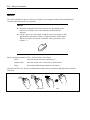
Do not remove the lithium battery.
Your server contains the lithium battery. Do not remove the battery. Placing
the lithium close to a fire or in the water may cause an explosion.
When the server does not operate appropriately due to the dead lithium
battery, contact your service representative. Do not disassemble the server to
replace or recharge the battery by yourself.
Disconnect the power plug before accessing inside the server, or connecting
the peripherals.
Make sure to power off the server and disconnect the power plug from a
power outlet before cleaning or installing/removing internal optional devices.
Touching any internal device of the server with its power cord connected to a
power source may cause an electric shock even of the server is off-powered.
Disconnect the power plug from the outlet occasionally and clean the plug
with a dry cloth. Heat will be generated if condensation is formed on a dusty
plug, which may cause a fire.
CAUTION
Avoid installation in extreme temperature conditions.
Immediately after the server is powered off, its internal components such as
hard disk drives are very hot. Leave the server until its internal components
fully cool down before installing/removing any component.
Make sure to complete board installation.
Always install a board firmly. An incompletely installed board may cause a
contact failure, resulting in smoking or fire.
Protect the unused connectors with the protective cap.
The unused power supply cable connectors are covered with the protective
cap to prevent short circuits and electrical hazards, when removing the power
supply cable connector from the install devices, attach the protective cap to
the connector. Failure to follow this warning may cause a fire or an electric
shock.
Notes on Using Your Server 1-7
During Operation
CAUTION
Stay away from the fan.
Keep your hand or hair away from the cooling fan on the rear of the server.
Failure to follow this warning may get your hand or hair caught in the fan,
resulting in injury.
Avoid contact with the server during thunderstorms.
Disconnect the power plug from the outlet when a thunderstorm is
approaching. If it starts thundering before you disconnect the power plug, do
not touch any part of the server including the cables. Failure to follow this
warning may cause a fire or an electric shock.
Keep animals away from the server.
Failure to follow this warning may cause a fire or an electric shock.
Do not leave the CD tray open.
If dust gets on the lens of DVD-ROM drive, the drive may have problems
reading your disks.
Also, the CD tray may be broken by contacting any objects.
Take off the headset before connection.
To protect your ears, take off the headset before connecting it to the headset
jack. Make sure that the volume is not extremely turned up before connection.
Do not place any object on top of the server.
The server may fall and cause property damage to the surroundings.
Do not use a cellular phone or pager around the server.
Turn off the cellular phone or pager. Radio interference may cause
malfunctions of the server.
1-8 Notes on Using Your Server
FOR PROPER OPERATION
Observe the following notes for successful operation of the server. Use of the server ignoring the
notes will cause malfunctions or failures of the server.
Install the server in a place that meets requirements for successful operation. For details,
see Chapter 3, "Setting Up Your Server."
If the power cord supplied with your system is not compatible with the AC wall outlet in
your region, contact your service representative to obtain a suitable power cord.
Make sure to power off the server before connecting or disconnecting cables between the
server and peripheral devices.
Verify that the access lamp on the server is unlit before turning off the server or ejecting
the floppy disk.
When plugging the power cord to the system, you may experience 10 seconds delay from
the time you press the POWER/SLEEP switch on the front panel. This is normal system
operation.
When you have just turned off the server, wait at least 10 seconds before turning it back
on. If the server is connected to the UPS, set at least 10 seconds delay in the power-on
schedule.
For the disk which does not conform to the CD standard, the playback of such a disk with
the CD drive is not guaranteed.
Turn off the power and unplug the power cord from the outlet before relocating the server.
Clean the server on a regular basis. (See Chapter 7 for cleaning.) Regular cleaning
proactively prevents various failures of the server.
Lightning may cause a momentary voltage drop. To prevent this problem, it is
recommended to use of an uninterruptible power supply unit.
Make sure to use optional devices supported by the server. Some non-supported devices
may be physically installed/connected but cause failures of the server as well as
malfunctions of the server.
NEC recommends you use NEC's genuine products. Some third-party products claim that
they support the server. However, repair of the server due to a failure or damage resulted
from use of such third-party products will be charged.
Notes on Using Your Server 1-9
TRANSFER TO THIRD PARTY
The following must be observed when you transfer (or sell) the server or software provided with the
server to a third party:
Make sure to provide this manual along with the server to a third party.
IMPORTANT: About data on the hard disk drive
Be sure to take appropriate measures not to leak important data (e.g.,
customers' information or companies' management information) on the
removed hard disk drive to any third parties.
Data seems to be erased when you empty "Recycle Bin" of Windows or
execute the "format" command of the operating system. However, the
actual data remains written on the hard disk drive. Data not erased
completely may be restored by special software and used for
unexpected purposes.
It is strongly recommended that the software or service (both available
at stores) for data erasure should be used in order to avoid the trouble
explained above. For details on data erasure, ask your sales
representative.
Provided software
To transfer or sell any software application that comes with the server to a third party, the following
requirements must be satisfied:
All provided software applications must be transferred and no backup copies must be
retained.
Transfer requirements listed in "Software License Agreement" that comes with each
software application must be satisfied.
Software applications that are not approved for transfer must be uninstalled before
transferring the server.
1-10 Notes on Using Your Server
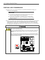
DISPOSAL AND CONSUMABLES
Dispose of the server, all the internal devices and DVD/CD-ROMs according to all
national laws and regulations.
IMPORTANT:
For disposal (or replacement) of the battery on the mother board of
the server, consult with your service representative.
It is the user's responsibility to completely erase or modify all the
data stored in storage device such as hard disk drive so that the data
cannot be restored.
Your server contains some components that are only good for a limited period of time and
require replacement, such as fans, internal batteries, the internal DVD-ROM drive, the
floppy disk drive, and the mouse. For stable operation of the server, NEC recommends
you replace these components on a regular basis. Consult with your service representative
for replacement or the product lives.
WARNING
Do not remove the lithium battery.
Your server contains the lithium battery. Do not remove the battery. Placing the
lithium or nickel cadmium battery close to a fire or in the water may cause an
explosion.
When the server does not operate appropriately due to the dead lithium battery,
contact your service representative. Do not disassemble the server to replace or
recharge the battery by yourself.
Mother board
Notes on Using Your Server 1-11
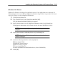
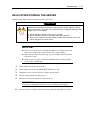
USER SUPPORT
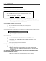
Before Asking for Repair, do the following when the server appears to fail:
1.
Check if the power cord and the cables to other devices are properly connected.
2.
See Chapter 8 to find if your problem fits the description. If it does, take the
recommended measure for it.
3.
Check if the software required for operation of the server is properly installed.
If the server still appears to fail after you have taken the above actions, consult with your service
representative immediately. Take notes on lamp indications of the server and alarm indications on
the display unit before consultation, which may provide a significant help to your service
representative.
1-12 Notes on Using Your Server
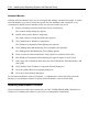
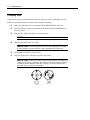
Advice for Health
The longer you keep using the computer equipment, the more you become
tired, which may cause disorders of your body. When you use a computer,
observe the following to keep yourself from getting tired:
Good Working Posture
You have good posture if the following are satisfied when you use a
computer:
• You sit on a chair with your back straight.
• Your hands are parallel with the floor when you put them on the
keyboard.
• You look at the screen slightly lower than your eye height.
You have "good working posture" as described in the above when no part
of your body is under excess strain, in other words when your muscles are
most relaxed.
You have "bad posture" when you sit with your back hunched up or you
operate a display unit with your face close to the screen. Bad working
posture may cause eye strain or poor eyesight.
Adjustment of Display Unit Angles
Most display units are designed for adjustment of the horizontal and
vertical angles. This adjustment is important to prevent the screen from
reflecting bright lights and to make the display contents easy to see. You
will not be able to keep "good working posture" and you will feel more tired
than you should if you operate a display unit without adjusting horizontal
and vertical angles.
Adjustment of Screen Brightness and Contrast
The display unit has brightness and contrast adjustment functions. The
most suitable brightness and contrast depend on the individual and the
working environment (well-lighted room or insufficient light). Adjust
brightness and contrast so that the screen will be easy to see. An
extremely bright or dark screen will give a bad effect to your eyes.
Adjustment of Keyboard Angle
The keyboard provided with the server is designed for adjustment of an
angle. Adjust the keyboard angle at which the keyboard is easy to operate.
The adjustment assists in reducing strain on your shoulders, arms, and
fingers.
Cleaning of Equipment
Clean equipment regularly. It is difficult to see the display contents on a
dusty screen. Keeping equipment clean is also important for your sight.
Fatigue and Rest
If you feel tired, you should stop working and do light exercises.
Chapter 2
General Description
This chapter provides information that you should be familiar with before using the server. It
includes names and functions of the components and features of the server.
2-2 General Description
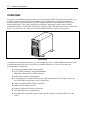
OVERVIEW
Your server is a modular, multiprocessing server based on the Intel® Xeon® processor family. It is
a solid performer and offers the latest technology. The combination of compute performance,
memory capacity, and integrated I/O provides a high performance environment for many server
market applications. These range from large corporations supporting remote offices to small
companies looking to obtain basic connectivity capability such a file and print services, e-mail, web
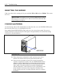
access, web site server, etc. Your server is housed and available as a tower-based system.
Front View
As application requirements increase, you can expand your server with an additional memory, addin boards and peripheral devices; tape devices, and hard disk drives. The server features the
following major components.
A high-performance Intel Xeon processor
Up to 24GB of memory (using 4GB DIMMs)
Minimum configuration is 1GB of memory
Dual channel memory configuration
Five integrated I/O expansion PCI slots for add-in boards (three PCI Express slots, one
64-bit/100 MHz slot and one 32-bit/33 MHz slot)
Onboard enhanced IDE interface controller
Onboard SAS RAID controller
Onboard 1000/100/10 network controller
Four hard disk drive expansion bays
Embedded PC-compatible support (serial, parallel, mouse, keyboard, USB, LAN, and
video)
General Description 2-3
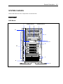
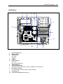
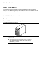
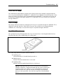
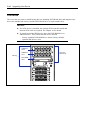
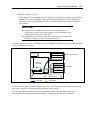
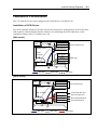
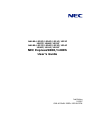
SYSTEM CHASSIS
Names and functions of the components are shown below.
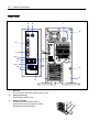
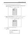
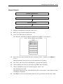
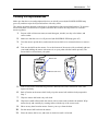
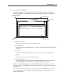
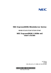
Front View
SAS Model
1
Additional slot 1
Additional slot 2
2
11
3
4
5
6
10
7
9
8
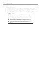
2-4 General Description
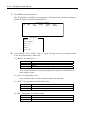
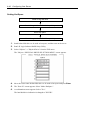
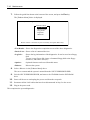
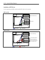
SATA Model
1
Additional slot 1
Additional slot 2
2
11
3
4
5
6
10
7
9
8
General Description 2-5
1
Front mask
The front mask protects the front face of the chassis.
2
DVD-ROM drive
The DVD-ROM drive reads data from the inserted CD-ROM or DVD-ROM.
The drive is equipped with the following:
• Open/Close button to eject the tray
• Access lamp that indicates the disk access status (lights orange while being accessed)
• Emergency hole to forcibly eject the tray
3
5.25-inch device bay
Backup file device of 5.25-inch width such as DAT drive or MO drive may be installed in the
5.25-inch device bay.
A DVD-ROM drive is factory-installed in the bottom bay.
To install a DVD-RAM drive or internal AIT (IDE), install it in the bottom bay. In this case, move
the DVD-ROM drive to the additional slot 1 and connect it as a master drive.
4
Disk access lamp (green)
The disk access lamp is lit while the system accesses to an internal hard disk drive. If the
internal hard disk drive is connected to the optional board, this lamp can be lit only when the
LED cable provided with the server is connected.
5
POWER/SLEEP lamp (green)
Lights green when the server is powered on. Blinks green when the system is placed in the
sleep mode.
6
POWER/SLEEP switch
The POWER/SLEEP switch is used to turn the power of the server ON/OFF. If you press this
switch once, the power is turned on with the lamp going on green. If you press the switch
again, the power is turned off.
Some OS setting can provide the function of switching to the power saving (sleep) mode. If
you press the POWER/SLEEP switch once after the setting, the system enters into the power
saving mode. If you press the switch again, the system returns to the normal state.
(Depending on installed optional boards, the function cannot be provided.)
7
USB connectors
The USB connectors are connected with devices accepting the USB interface.
8
Stabilizer
Use the stabilizers to prevent the server from falling down. Close the stabilizers when laying
the server down.
9
Hard disk drive bay
The bay can contain hard disk drives.
10
Release tabs (4 at an end of front mask)
The release tabs are provided to unlock the front mask. Press the tabs to remove the front
mask.
11
3.5-inch floppy disk drive bay
The bay can contain an internal USB floppy disk drive (option).
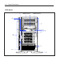
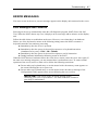
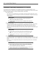
2-6 General Description
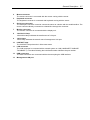
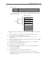
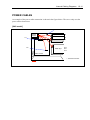
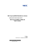
Rear View
5
4
1
2
6
7
11-1
10
8
10
8
11-2
10
13
12
9
1
AC inlet
The AC inlet is connected with the power cord.
2
Fixing screws (2)
Secures the left side cover.
3
Cover lock plate
Installing a theft prevention device
protects the internal components of the
workstation from being stolen.
3
2
General Description 2-7
4
Mouse connector
The mouse connector is connected with the mouse coming with the server.
5
Keyboard connector
The keyboard connector is connected with keyboard coming with the server.
6
Serial port connector
The serial port connector is used to connect the server to a device with the serial interface. The
server cannot be directly connected to a leased line through the connector.
7
Monitor connector
The monitor connector is connected with the display unit.
8
1000/100/10 lamp
1000/100/10 lamp indicates the transfer rate of LAN port.
9
100/10 lamp
100/10 lamp indicates the transfer rate of management LAN port.
10
LINK/ACT lamp
The LINK/ACT lamp shows the LAN access status.
11
LAN connector
The LAN connector is connected with a network system on LAN (1000BASE-T/100BASETX/10BASE-T). The value following the bold-faced number indicates the port number.
12
USB connectors
The USB connectors are connected with devices accepting the USB interface.
13
Management LAN port
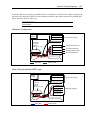
2-8 General Description
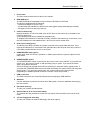
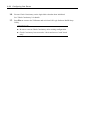
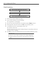
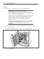
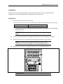
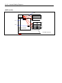
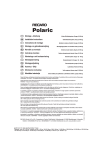
Internal View
SAS Model
1
2
4
5-1 6
7
3-2
8
3-1
5-2
10
9
General Description 2-9
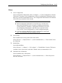
SATA Model
1
2
4
5-1 6
7
3-2
8
3-1
5-2
1
2
3
4
5
6
7
8
9
10
10
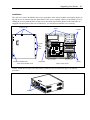
9
Power supply unit
Mother board
Cooling fan
3-1 Front
3-2 Rear
DIMMs
CPU heat sink
5-1 CPU 1
5-2 CPU 2 (additional)
DVD-ROM drive
5.25-inch device bay
A standard DVD-ROM drive is factory-installed in the bottom slot.
Hard disk drive bay
For SAS model, the HDD cage is factory installed.
PCI guide rail
3.5-inch hard disk drive (optional)
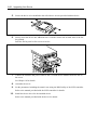
2-10 General Description
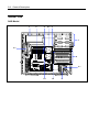
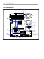
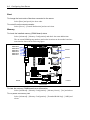
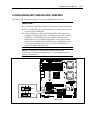
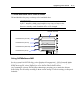
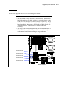
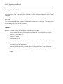
MOTHER BOARD
20
2
4-1
3
1-1
19
1-2
4-2
2
18
5-5
5-4
6
7
4-5
4-4
5-0 to 5-3
17 16 15
13
14
12-5 12-6
12-1 to 12-4
11
10
9
8 4-3
General Description 2-11
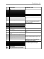
1
2
3
4
5
6
7
8
9
10
11
12
13
14
15
16
17
18
19
20
Processor socket
1-1 CPU1 socket
1-2 CPU2 socket
Power connectors
DIMM sockets
(DIMM #A-1, #A-2, #A-3, #B-1, #B-2, and #B-3 from bottom to top)
Cooling fan connector
4-1: CPU1 heat sink fan
4-2: CPU2 heat sink fan
4-3: Front fan
4-4: Rear fan
4-5: VR fan
SAS connector
(Not provided for SATA model. The last digit shows a channel number.)
Connector for RAID5 activation key
SAS SW RAID select jumper switch (Not provided for SATA model.)
See Chapters 4 and 9 for switch setting.
Disk LED connector
USB port connector
USB device connector
IDE connector
Serial ATA connector
(12-1 to 12-4 are not provided for SAS model. The last digit shows a channel number.)
Lithium battery
Switch/LED cable connector
CMOS configuration jumper switch
Serial port B connector (for option device)
IPMB connctor
PCI board slots (#1 to #5 from top)
18-1: PCIe ×4
18-2: 64-bit/100MHz PCI-X
18-3: PCIe ×8
18-4: PCIe ×1 (connector: ×4)
18-5: 32-bit/33MHz PCI
Connector for external device
Reserved
2-12 General Description
STANDARD FEATURES
High performance
Dual-Core Intel Xeon Processor
High-speed 1000BASE-T/100BASETX/10BASE-T interface
(1Gbps/100Mbps/10Mbps supported)
High-speed disk access (SATA2)
Dual channel memory configuration
Expandability
Large memory of up to 24GB
(six 4GB DIMMs)
USB interface (USB 2.0)
Five integrated I/O expansion PCI slots
- PCI Express (x8): 1 slot
- PCI Express (x4): 1 slot
- PCI Express (x1): 1 slot
- PCI-X (64-bit/100 MHz): 1 slot
- PCI bus (32-bit/33 MHz): 1 slot
Serial ATA x6 channels
(x2 channels for SAS model)
Ultra ATA 100 x1 channel
Up to two multi-processors
Can be used as rack-mount type.
(N81243-64F rack conversion kit is
required.)
High-reliability
Many Available Features
El Torito Bootable CD-ROM (no emulation
BIOS password feature
mode) format support
Temperature detection
Cooling fan monitoring feature
Remote power-on feature
AC-LINK feature
Internal voltage monitoring feature
Disk array (SATA)
Memory monitoring feature (single-bit
IPMI v2.0 compliant Baseboard
error correction/double-bit error detection)
Management Controller (BMC)
CPU/memory degradation feature
Disk array (SATA2/SAS)
Self-diagnosis
Bus parity error detection
Error notification
Power On Self-Test (POST)
Test and Diagnosis
Management Utilities
NEC ESMPRO
Off-line Maintenance Utility
NEC DianaScope
NEC EXPRESSSCOPE Engine
Power Saving Feature
Sleep feature
(available for Windows Server 2003)
Easy and Fine Setup
NEC EXPRESSBUILDER (system setup
utility)
BIOS setup utility
Configuration Diskette Creator
General Description 2-13
Power Supply
The system contains one auto-sensing 600-watt power supply at an operating frequency of 50/60
Hz.
The power supply is designed to comply with existing emission standards and provide sufficient
power for a fully loaded system configuration.
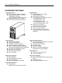
Peripheral Bays
The system supports a variety of standard PC AT-compatible peripheral devices. The chassis
includes these peripheral bays:
Three 5.25-inch file bays for installing 5.25-inch peripheral devices such as an optional
tape drives. (A DVD-ROM drive is factory-installed.)
The 3.5-inch device bays for installing up to four SATA or SAS hard disk drives.
Remote Power-On Feature (Wake On LAN)
The remote power-on function turns on the server through a network. It sends a special packet from
the management computer to a remote server to turn it on if the server is off-powered.
To enable this feature, you must select "Enabled" for each submenu in the Power Management
Setup of the Advanced menu of the BIOS setup utility, "SETUP." (See Chapter 4.)
The remote power-on feature is not available in the following cases. Press the POWER/SLEEP
switch once to start the OS, and turn off the server in an appropriate procedure.
Abnormal previous system shut-down
No power supply to the server (due to turned-off breaker, disconnected power cord, power
blackout, etc.)
AC LINK Feature
When the power cord of the server is connected to an uninterruptible power supply (UPS) unit, the
server supports the power linkage feature that enables control over the power supply from the UPS
to the server. The AC LINK feature can be enabled or disabled with Power Management Setup in
the Server menu of the BIOS setup utility, "SETUP." (See Chapter 4.)
Security
The BIOS setup utility provides a number of security features to prevent unauthorized or accidental
access to the system. Once the security measures are enabled, access to the system is allowed only
after the user enters the correct password(s). For example:
Set and enable an administrative password.
Set and enable a user password
Check the user account when entering the BIOS setup utility or booting the system.
2-14 General Description
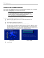
NEC EXPRESSBUILDER
The CD-ROM that comes with the server contains a setup utility called "NEC
EXPRESSBUILDER."
The major functions of the NEC EXPRESSBUILDER are:
To install the Operating System.
"Express Setup" helps you to install the Windows Operating System. (See Chapter 5)
To diagnose the system.
NEC EXPRESSBUILDER includes the System Diagnostics to check your server. (See
Chapter 6)
To create support disks.
Use this function to create the support disks used to boot the utilities from the floppy disk,
or the OEM floppy disk used for a manual installation of Windows. (See Chapter 6)
To update the BIOS.
Use this function to update the system BIOS or firmware of the server. (See Chapter 6)
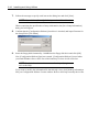
To update the Windows System*
"Update Express5800 system" in Master Control Menu (Windows-based NEC
EXPRESSBUILDER feature) updates the several drivers of Microsoft Windows. (See
Chapter 6)
To install the utilities.
NEC EXPRESSBUILDER includes some management software for Windows (NEC
ESMPRO, NEC DianaScope and so on) and maintenance utilities for DOS (System
diagnostics, Off-line Maintenance Utility and so on).
You can install the applications for Windows from Master Control Menu and install the
utilities for DOS from Tools menu. (See Chapter 6)
To read the online documents*
You can refer to the online documents from Master Control Menu. (See Chapter 6)
* These functions are available under the Windows system.
NOTE: Some features among those listed above can be used from the
remote computer via cross cable (COM), or LAN. See Chapter 6 for
details.
NEC ESMPRO
The NEC ESMPRO is server management software that runs on the OS. The NEC ESMPRO
includes the NEC ESMPRO Manager for the server monitoring terminal and the NEC ESMPRO
Agent for the NEC Express server.
NOTE: For details of major functions of the NEC ESMPRO, system
configuration and setups with the NEC ESMPRO, see Chapter 6.
Available functions of the NEC ESMPRO depend on the OS you install.
Ask your service representative for details.
General Description 2-15
Off-line Maintenance Utility
The Off-line Maintenance Utility is used for maintenance and fault analysis of the server. This
utility is usually used by the service representative. See Chapter 8 for details.
System Diagnostic Utility
The system diagnostic utility contained in the NEC EXPRESSBUILDER is useful to detect
hardware failures. See Chapter 7 for details.
Remote Management
The server may be monitored and managed via LAN/WAN by installing the optional Remote
Management (N8115-03) and NEC DianaScope utility. To use the NEC DianaScope, a separately
priced server license is required.
The Remote Management performs the following:
Monitoring of temperature, voltage, and fans
Generation of SEL (system event log) at occurrence of hardware failure
Monitoring of OS stall by using watchdog timer
Notification after occurrence of OS stop error
Remote management via LAN/WAN by using NEC DianaScope (e.g., resetting the server,
power on/off, viewing System Event Log (SEL))
NOTES:
Notes on using Remote Management (N8115-03)
– Booting the server from the NEC EXPRESSBUILDER CD by
using the Remote Media function is not available.
– For the latest information about Remote Console/Remote Media
function, visit our web site.
The following functions are not supported in the command line
interface of EXPRESSSCOPE Engine.
– Power state acquisition
– STATUS LED state acquisition
2-16 General Description
USING YOUR SERVER
This section describes basic operations of your server including how to use devices such as the
floppy disk drive and the DVD-ROM drive. See Appendix B for notes on using the floppy disk, CDROM, and accessories including the keyboard and the mouse.
POWER Switch
Use the POWER/SLEEP switch to turn on/off the server.
Power On
Press the POWER switch on the front of the computer chassis.
The POWER/SLEEP lamp lights in green.
IMPORTANT:
If the power cord is connected to a power control device such as a
UPS (Uninterruptible Power Supply), make sure that the power
control device is powered.
Do not turn off the server until characters appear on the screen.
General Description 2-17
POST
POST (Power On Self-Test) is the self-diagnostic program stored in the system memory.
When you power on the server, the system automatically runs POST to check the mother board,
ECC memory module, CPU module, keyboard, and mouse. POST also displays messages of the
BIOS Setup utility, such as the start-up message, while in progress.
With the factory setup of the server, the NEC logo appears on the display unit while POST is in
progress. (To display the POST check results, press Esc.)
You don't always need to check the POST check results. Check messages that POST displays when:
you use the NEC Express server for the first time.
the server appears to fail.
the server beeps for many times between power-on and OS start-up.
an error message appears on the display unit.
2-18 General Description
POST Execution Flow
The following describes the progress of POST in the chronological order.
IMPORTANT:
Do not power off the server while POST is in progress.
Do not make key entries or perform mouse operations while POST
is in progress.
Some system configurations may display the message "Press Any
Key" to prompt a key entry. This message is driven by BIOS of an
installed optional board. Make sure to read the manual that comes
with the optional board before any key entry.
Powering on the server, after you installed or removed an optional
PCI board or moved it to another slot, may display the message that
indicates incorrect board configuration and suspend POST.
In such a case, press F1 to continue POST. Board configuration can
be made using the utility described later.
1.
After a few seconds from power-on, POST starts checking the memory. The count
message of the basic and expansion memory appears at top left on the display unit screen.
The memory check may takes a few minutes to complete depending on the memory size
of the server. Also, it may take approximately one minute for the screen display to appear
after rebooting the server.
2.
Some messages appear upon completion of the memory check. These messages appear to
indicate that the system has detected the CPU, keyboard, and mouse.
3.
After a few seconds, POST displays the following message prompting you to launch the
BIOS SETUP utility, stored in the system memory of the server. This message appears at
bottom left on the screen.
Press <F2> to enter SETUP or Press <F12> to boot from Network
Launch the BIOS setup utility when you need to change the settings to meet the
requirements for the server. As long as the above message is not displayed with an error
message, you don't have to launch the utility. (Ignore the message. POST will
automatically proceed.)
To launch the BIOS setup utility, press F2 while the above message is displayed. See
Chapter 4 for setup and parameters.
The server automatically restarts POST all over again when you exit the SETUP utility.
4.
If your server uses onboard SAS RAID feature, the following message is displayed on the
screen to prompt you to run the utility.
Press Ctrl-M to run LSI Logic Software RAID Setup Utility
Press Ctrl + M to run the utility. For detail explanation, see Chapter 4 for detail.
General Description 2-19
5.
If the POST detects the optional add-in card, it display the message prompting you to
launch the add-in card BIOS configuration utility. (Ignore the message. POST will
automatically proceed a few seconds later.)
Refer to the manual that comes with the optional add-in card for detail.
6.
If you set a password using the BIOS SETUP utility, the password entry screen appears
upon successful completion of POST.
Up to three password entries will be accepted. Three incorrect password entries disable
the server to boot. In such a case, turn off the power and wait about ten seconds before
turning on to boot the server.
IMPORTANT: Do not set a password before installing an OS.
7.
The OS starts when POST completes.
POST Error Messages
When POST detects an error, it displays an error message on the display unit screen or emits beep
code. See Chapter 8 for POST error codes.
IMPORTANT: Take a note on the messages displayed before
consulting with your service representative. Alarm messages are useful
information for maintenance.
2-20 General Description
Power Off
Follow the procedure below to power off the server. If the power cord of the server is connected to a
UPS, refer to the manual that comes with the UPS or the manual for the application that controls the
UPS.
IMPORTANT: Always allow POST to complete before turning off the
server.
1.
Shut down the OS.
2.
Press the POWER/SLEEP switch on the front of the server.
The POWER/SLEEP lamp goes out.
3.
Power off peripheral devices.
NOTE: The standby function of Windows Server is not available. Do
not select "Standby" in the Windows shutdown menu.
SLEEP Switch
The POWER/SLEEP switch allows you to save almost all power of the server (power-saving mode
or sleep mode).
Press the POWER/SLEEP switch on the front of the server to place the server in the power-saving
mode. (The POWER/SLEEP lamp blinks.) In the power-saving mode, the server retains the memory
data and the status of the previous operations.
To resume the original state, press the POWER/SLEEP switch again. (It may take a little time to
resume the original state.)
NOTE: The operational level in the power-saving mode depends on
the OS in use. (Available for Windows Server 2003.)
General Description 2-21
DVD-ROM Drive
The server is provided with the DVD-ROM drive on its front to read data from a disc.
CAUTION
Observe the following instructions to use the server safely. Failure to follow
these instructions may cause a fire, personal injury, or property damage. See
pages 1-3 to 1-8 for details.
■
■
Do not leave the tray ejected from the DVD-ROM drive.
Take off the headphone before you plug in the headphone jack.
Setting and Removing the Disc
1.
Make sure that the power of the server is on (with the POWER/SLEEP lamp being lit in
green) before setting the disc on the DVD-ROM drive.
2.
Press the Open/Close button on the front of the DVD-ROM drive.
The tray comes out.
3.
Put the disc on the tray carefully and securely with the character printed surface facing
upward.
4.
Press the Open/Close button or gently push on the tray front.
The tray is automatically retracted into the DVD-ROM drive.
IMPORTANT: If a noisy sound in driving the DVD-ROM drive occurs
after setting a disc, set it again correctly.
To take out the disc from the DVD-ROM drive, press the Open/Close button in the similar way in
setting the disc to make the tray go out. If the access LED is lit in orange, the disc is being accessed.
Confirm that the access LED is not lit before pressing the Open/Close button.
Your OS may have a command to eject the tray.
When you have taken out the disc, retract the tray back in place.
2-22 General Description
When you fail to eject:
When you fail to eject the tray with the Open/Close button and take out the disc from the server,
follow the procedure below.
1.
Press the POWER switch to power off the server. (The POWER/SLEEP lamp goes off.)
2.
Insert a metal pin of approximately 1.2 mm in diameter and 100 mm in length (a
straightened large paper clip will make a substitute) into the emergency hole on the front
of the DVD-ROM drive and gently push it in until the tray is ejected.
Emergency hole
IMPORTANT:
Do not use a toothpick or plastic stick that is easy to break.
If the above procedure does not let you take out the DVD/CD-ROM,
contact your service representative.
3.
Hold the tray and pull it out.
4.
Take out the disc.
5.
Push the tray back into position.
General Description 2-23
Use of the Disc
Keep the following notes in mind to use the disc for the server:
For the disk which does not conform to the CD standard, the playback of such a disk with
the CD drive is not guaranteed.
Do not drop the disc.
Do not place anything on the disc or bend the disc.
Do not attach any label onto the disc.
Do not touch the signal side (nothing is printed on this side) with your hand.
Place the disc with its printed side upward and gently put it on the tray.
Do not scratch the disc or write anything directly on it with a pencil or ball-point pen.
Keep the disc away from cigarette smoke.
Do not leave the disc in a high-temperature place (e.g., place exposed to direct sunlight or
close to a heater).
When dust or fingerprints are attached on the disc, wipe the disc from its center to edge
with a dry soft cloth slowly and gently.
Use the CD cleaner to clean the disc. Do not use record spray/cleaner, benzene, or thinner.
Keep the disc in a disc case when not in use.
If the disc emits large noise in the DVD-ROM drive, remove the disc and insert it back
again.
2-24 General Description
(This page is intentionally left blank.)
Chapter 3
Setting Up Your Server
This chapter describes how to set up your server appropriate for your system, on a step-by-step
basis.
3-2 Setting Up Your Server
SETUP FLOW
Follow the flowchart below to set up the server.
Unpacking the system
Unpack the server and accessories from the shipping carton box.
Installing optional devices
If you have purchased any optional device for the server, see Chapter 9 to install it.
Selecting the server site
Select a suitable site for the server.
Connecting peripheral devices
Connect peripheral devices to the server.
Connecting the power cord
Connect the power cord to the server.
Turning on the server
Power on the server to start software setups. Setups depend on the optional internal
devices installed and the peripheral devices connected.
Installing the operating system
Install an operating system to the server. See Chapter 5.
Installing the utilities
Install the utilities in the provided NEC EXPRESSBUILDER CD-ROM.
See Chapter 6.
Making backup copies of system information
After all the system setup procedures are completed, make backup copies of system
information.
System information is required for recovering the server from the trouble or after
replacing the system board.
Setting Up Your Server
3-3
UNPACKING THE SYSTEM
When you receive your system, inspect the shipping containers prior to unpacking. If the shipping
boxes are damaged, note the damage, and if possible, photograph it for reference. After removing
the contents of the containers, keep the cartons and the packing materials. If the contents appear
damaged when you unpack the boxes, file a damage claim with the carrier immediately.
INSTALLING OPTIONAL DEVICES
To install any optional device, see Chapter 9, "Upgrading Your Server," for the installation
procedure. Proceed to the next section if you have no optional devices to install.
IMPORTANT: There are third-party products (memory modules, hard
disk drives, etc.) available for the server in the markets. However, NEC
recommends that you should use NEC products for stable operation.
NEC assumes no liability for data errors and failures due to malfunction
of the server resulted from installation of those third-party products.
3-4 Setting Up Your Server
SELECTING SERVER SITE
Read the following precautions before selecting a suitable site for your server. The following
describes installation of the server and connections to the server.
CAUTION
Observe the following instructions to use the server safely. Failure to follow
these instructions may cause a fire, personal injury, or property damage. See
pages 1-3 to 1-8 for details.
■
■
Never attempt to lift the server only by yourself.
Do not install the server in any place other than specified.
The following figure illustrates a site suitable for installing the server.
Allow clearance of at least 150 mm in
front of and behind the server.
Close enough to connect the
mouse and the display.
Room that satisfies the
following conditions: *
<While operating>
Temperature: 10 to 35ºC
Humidity: 20 to 80%
Temperature gradient: ±10ºC/h
Atmosphere: 749 to 1040 hpa
<While halting>
Temperature: –10 to 55ºC
Humidity: 10 to 80%
Temperature gradient: ±15ºC/h
Atmosphere: 749 to 1040 hpa
Install the server on
a flat, rigid desk
The server must be
fixed with stabilizers.
100 to 120 Vac/200 to 240
Vac parallel bi-polar wall
power outlet with the
ground line.
Clean and tidy room
* It is recommended that the server should be used in a room where
temperature is in the range between 15 to 25ºC.
Setting Up Your Server
3-5
When you have selected a server site, hold the server by its bottom with at least three persons and
carry it to the site, then place it slowly and gently.
IMPORTANT: Do not hold the server by its front mask to lift the
server. The front mask may be disengaged and damage the server.
Do not install the server in the following locations as it may cause malfunctions of the server.
Places with drastic changes in temperature (e.g., near a heater, air conditioner, or
refrigerator)
Places with strong vibration
Places with corrosive gas in presence, near chemicals, or with possibilities of chemicals
sprayed over
On a non-antistatic carpet
Places with possibilities of falling objects
Places where a power outlet that shares the ground line with another (especially the one to
which a device with large power consumption is connected) must be used for the server
Places near a device generating intense magnetic field (such as a TV, radio,
broadcast/communication antenna, power transmission wire, and electromagnetic crane) is
placed
Places near equipment that generates power noise (e.g., contact spark at power-on/power
off of commercial power supply through a relay). If you must install the server close to
such equipment, request your service representative for separate power cabling or noise
filter installation.
3-6 Setting Up Your Server
CONNECTING PERIPHERAL DEVICES
Connect peripheral devices to the server. The server is provided with connectors for wide variety of
peripheral devices. The figure on the next page illustrates available peripheral devices for the server
in the standard configuration and locations of the connectors for the devices.
CAUTION
Observe the following instructions to use the server safely. Failure to follow
these instructions may cause a fire, personal injury, or property damage. See
pages 1-3 to 1-8 for details.
■
■
■
■
Do not use any damaged cable connector.
Do not use any unauthorized interface cable.
Do not use the server with any loose interface connection.
Do not step on the interface cable or place any heavy object on it.
IMPORTANT:
Power off the server and a peripheral device before connection.
Connecting a powered peripheral device to the powered server will
cause malfunctions and failures.
To connect a third-party peripheral device or interface cable to the
server, consult with your service representative for availability of
such a device or cable. Some third-party devices may not be used
for the server.
To connect the provided keyboard and mouse, plug their connectors
to the server with the "∆" mark on the connectors facing right.
Do not connect the serial ports with the telephone line directly.
Do not connect any devices to the connectors not instructed in this
subsection. Doing so could damage the device, your server, or both.
Setting Up Your Server
3-7
FRONT
Device with the USB interface
(e.g., terminal adapter)
REAR
Mouse
Finally connect the
power cord to the
receptacle.
Keyboard
Device with the serial
interface (e.g., modem)*
Hub
(multiport repeater)
LAN ports
(1000BASE-T/
100BASE-TX/
10BASE-T)
Display unit
Device with the USB interface
(e.g., terminal adapter)
Management LAN port
(100BASE-TX/10BASE-T)
Hub
(multiport repeater)
3-8 Setting Up Your Server
CONNECTING POWER CORD
Connect the provided power cord to the server.
WARNING
Observe the following instructions to use the server safely. Failure to follow
these instructions may result in death or serious personal injury. See pages
1-3 to 1-8 for details.
■
Do not hold the power plug with a wet hand.
CAUTION
Observe the following instructions to use the server safely. Failure to follow
these instructions may cause a fire, personal injury, or property damage. See
pages 1-3 to 1-8 for details.
■
■
■
■
Do not plug the power cord in to an improper power source.
Do not connect the power cord to an outlet that has an illegal number of
connections.
Insert the power plug into the outlet as far as it goes.
Use the authorized power cord only.
1.
Plug the provided power cord into the power receptacle on the rear of the server.
2.
Plug the other end of the power cord into the wall outlet.
Setting Up Your Server
NOTES:
To connect the power cord from the server to an interruptive power
supply (UPS), use service outlets on the rear of the UPS.
Refer to the manual that comes with the UPS for details.
Connect the battery
connector when using
UPS.
Disconnect the connector
when moving the UPS to
relocate it.
When the power cord from the server is connected to a UPS, change
the BIOS SETUP utility of the server to link with power supply
from the UPS.
Change a parameter for "AC-LINK" of the Server menu of the
BIOS SETUP utility. See Chapter 4 for details.
3-9
3-10 Setting Up Your Server
TURNING ON THE SERVER
Turn on the server and follow the on-screen instructions for setup.
IMPORTANT: Before turning on the server:
Some optional boards require setups with the BIOS setup utility
before installation. If the server has a PCI board with the PCI-toPCI bridge installed, the BIOS setup utility is enabled to launch.
Check on the board specifications to find out whether it requires
pre-installation setups before actually installing the board.
Some installed optional devices or connected peripheral devices
require setups before proceeding to the next step.
To use the server with no optional devices installed besides the graphic
board, install a desired OS to the server.
1.
Make sure all external devices, such as a video display, keyboard, and mouse have been
connected, and the power cords are connected.
2.
Power on the video display and any other external devices.
3.
Make sure that the floppy disk drive contains no floppy disk and the DVD-ROM drive
contains no bootable DVD/CD-ROM.
4.
Press the POWER/SLEEP switch.
NOTES:
If the power cord is connected to the power control unit such as the
UPS, turn on the power control unit.
Connect the power cord and wait a few seconds before pressing the
POWER switch. The POWER/SLEEP switch does not work in a
few seconds after connecting the power cord due to firmware startup.
Setting Up Your Server
3-11
The POWER/SLEEP lamp on the front of the server comes on.
In a few seconds, the NEC logo appears on the screen and the Power On Self-Test (POST)
begins.
The POST runs automatically when you power on the server or reset it with a keyboard
operation (Ctrl + Alt + Delete). The POST runs diagnostics, initializes the server, sets
interrupt vectors, detects installed peripheral devices, and boots the operating system (if
installed). See Chapter 2 for detailed description on POST.
If the server halts before completing the POST, the POST emits a beep code indicating a
fatal system error requiring immediate attention. (See Chapter 8, "Troubleshooting," for
troubleshooting information.)
During memory test, the POST displays the amount of memory it was able to access and
test. Depending on the amount of installed memory, it may take several minutes to
complete the memory test.
NOTE: The factory-set is defined to hide the POST screen with the
NEC logo screen. You can always change the NEC logo screen to the
POST screen by pressing Tab. To change the start-up screen, use the
BIOS setup utility. (See Chapter 4 for details.)
During the POST, you will see the banner message to prompt you to launch the BIOS setup utility
stored in ROM on the mother board or on an installed option board.
Start the BIOS setup utility appropriate to your system environment to change the CMOS Setup. For
detail explanation on the BIOS setup utility for the server, see Chapter 4. For the BIOS utility for
the option board, refer to the manual that comes with the option board.
IMPORTANT: Always allow POST to complete before turning off
your system.
3-12 Setting Up Your Server
INSTALLING OPERATING SYSTEM
See Chapter 5 for installing Microsoft Windows Server 2003.
To install the other operating system, contact your service representative.
INSTALLING UTILITIES
Install the utilities that come with the server. See Chapter 6 for details.
MAKING BACKUP COPIES OF SYSTEM INFORMATION
The system information includes the current BIOS settings and any specific information for the
server.
Save the information after completing the system setup.
Without the backup data, you will not be able to recover the information.
You can save the information by the following process.
1.
Insert the "NEC EXPRESSBUILDER" CD-ROM into the DVD-ROM drive and reboot
the system.
2.
Select [Tools].
3.
Select [Off-line Maintenance Utility].
4.
Select [System Information Management].
5.
Insert a floppy disk into the floppy disk drive.
6.
Select [Save].
Chapter 4
Configuring Your Server
Configuration and setup utilities are used to change your system configuration. You can configure
your system, as well as option boards you may add to your system, using the BIOS Setup utility.
Several unique system parameters are configured using the BIOS Setup utility, which is stored in
the system FLASH memory.
If your system has been factory configured, the BIOS Setup utility or RAID Configuration Utility
do not need to be run unless you want to change the password or security features, add certain types
of option boards or devices, or upgrade your mother board.
This chapter also provides information on several system configuration parameters that are set by
jumpers on the system board. However, these parameters do not usually require change.
Use NEC EXPRESSBUILDER CD-ROM to create the device driver diskettes.
4-2 Configuring Your Server
SYSTEM BIOS (BIOS SETUP UTILITY)
The BIOS Setup utility is provided to make basic hardware configuration for the server. This utility
is pre-installed in the flash memory of the server and ready to run.
The server is configured with the correct parameters using the BIOS Setup utility and shipped in the
best conditions. Thus, you don't need to use the BIOS Setup utility in most cases. However, you
might wish to use the BIOS Setup utility in the cases described below.
IMPORTANT:
The BIOS Setup utility is intended for system administrator use
only.
The BIOS Setup utility allows you to set a password. The server is
provided with two levels of password: Supervisor and User. With
the Supervisor password, you can view and change all system
parameters of the BIOS Setup utility. With the User password,
system parameters available for viewing and changing are limited.
Do not set any password before installing the OS.
The server contains the latest version of the BIOS Setup utility.
Dialog boxes appear on your BIOS Setup utility, thus, may differ
from descriptions in this manual. If you find anything unclear, see
the online help or ask your service representative.
Configuring Your Server
4-3
Starting SETUP Utility
A few seconds after powering on, the following message appears at bottom left on the screen.
If NEC logo appears instead, press Esc.
Press <F2> to enter SETUP or Press <F12> to boot from Network
Press F2 to start the BIOS Setup utility and display its Main menu.
If you have previously set a password with the BIOS Setup utility, the password entry screen
appears. Enter the password.
Enter password:[
]
Up to three password entries will be accepted. If you fail to enter the password correctly for three
consecutive times, the server halts. (You can no longer proceed.) Power off the server.
NOTE: The server is provided with two levels of password:
Supervisor and User. With the Supervisor password, you can view and
change all system parameters. With the User password, system
parameters available for viewing and changing are limited.
4-4 Configuring Your Server
Description on On-Screen Items and Key Usage
Use the following keyboard keys to work with the BIOS Setup utility. These keys are also listed at
the bottom of the menu screen.
Indicates there are submenus.
Indicates the current menu.
Setup item
menu
Online
help
window
Explanation of key functions menu
Cursor (↑, ↓):
Cursor (←, →):
– and +:
Enter
Esc
F1:
F9:
F10:
Parameter (high-lights upon selection) menu
Move cursor up and down. The cursor moves only to the settings
that you can change.
Move between menus.
Select the previous value (–) or the next value (+) for the field.
Execute command or select ³ submenu.
Exit the current menu and return to the previous menu.
Get Help about an item. Press Esc to return to the previous menu.
Load default configuration values for this menu.
Save configuration values and exit.
Configuring Your Server
4-5
Configuration Examples
The following describes examples of configuration required to use software-link features or for
system operations.
Time and Date Settings
You can also change the time and date settings via the operating system commands.
Select [Main] - [System Time].
Select [Main] - [System Date].
Link with Management Software
To control power supply of the server with NEC ESMPRO Manager via the network
Select [Advanced] - [Advanced Chipset Control] - [Wake On LAN/PME] - [Enabled].
Select [Server] - [AC LINK] - [Stay Off].
Hard Disk Drive
To check the hard disk drive status
Select [Main] - [Primary IDE Master] and check the status indications.
To configure the SW RAID (on-board) with SATA hard disk drives
Select [Advanced] - [Peripheral Configuration] - [SATA Controller Mode Option] [Enhanced]. Then select [Advanced] - [Peripheral Configuration] - [SATA RAID] [Enabled], and configure the RAID drive.
IMPORTANT: Be sure to set to [Enabled] after executing [Load
Setup Defaults] or CMOS clear. Leaving this parameter as the factoryset value (Disabled) may destroy the data in hard disk drive.
UPS
To link power supply with the UPS
To power on the server when power is supply from the UPS
Select [Server] - [AC LINK] - [Power On].
To keep the server off-powered even when power is supplied from the UPS
Select [Server] - [AC LINK] - [Stay Off].
To keep the server off-powered even when power is supplied from the UPS if the POWER
switch was used to power off
Select [Server] - [AC LINK] - [Last State].
4-6 Configuring Your Server
Boot
To change the boot order of devices connected to the server
Select [Boot] and specify the boot order.
To control from the remote console
Select [Server] - [Console Redirection] and set each item.
Memory
To check the installed memory (DIMM board) status
Select [Advanced] - [Memory Configuration] and check the status indications.
The on-screen DIMM group numbers and socket locations on the mother board are
associated as shown in the following figure.
DIMM #B-3
DIMM #B-2
DIMM #B-1
DIMM #A-3
DIMM #A-2
DIMM #A-1
CPU #1
CPU #2
REAR
FRONT
Motherboard
To clear the memory (DIMM board) error information
Select [Advanced] - [Memory Configuration] - [Memory Retest] - [Yes] and reboot.
To run power-on memory test
Select [Advanced] - [Memory Configuration] - [Extended RAM Step] - [1MB] and
reboot.
Configuring Your Server
4-7
CPU
To check the installed CPU status
Select [Main] - [Processor Settings] and check the status indications.
The on-screen processor numbers and socket locations on the motherboard are associated
as shown in the figure on the previous page.
To clear the CPU error information
Select [Main] - [Processor Settings] - [Processor Retest] – [Yes] and reboot.
Keyboard
To set Numlock
Select [Advanced] - [Numlock] – [On]/[Off].
Event Log
To clear event logs
Select [Server] - [Event Log Configuration] - [Clear all Event Logs], press Enter, and
select [Yes].
Security
To set passwords on the BIOS
Select [Security] - [Set Supervisor Password] and enter a password.
Select [Security] - [Set User Password] and enter a password.
Set Supervisor password first, then User password.
External Devices
To set up external devices
Select [Advanced] - [Peripheral Configuration] and set up each device.
Internal Devices
To install the disk array controller board or SCSI controller board
Select [Advanced] - [PCI Configuration] - [PCI Slot n Option ROM] - [Enabled].
n: slot number
To clear the hardware configuration data (after installing/removing internal devices)
Select [Advanced] - [Reset Configuration Data] - [Yes].
4-8 Configuring Your Server
Saving the Configuration Data
IMPORTANT: If the SATA hard disk drives are used in disk array
configured with the on-board HostRAID, be sure to select [Advanced] [Peripheral Configuration] - [SATA Controller Mode Option] [Enhanced]. Then, select [Advanced] - [Peripheral Configuration] [SATA RAID Enable] - [Enabled]. Leaving this parameter as the
factory-set value (Disabled) may destroy the data in hard disk drive.
To save the current configuration data
Select [Exit] - [Exit Saving Changes] or [Save Changes].
To discard changes to the current configuration data
Select [Exit] - [Exit Discarding Changes] or [Discard Changes].
To load the user-defined default
Select [Exit] - [Load Setup Defaults].
To load the custom defaults
Select [Exit] - [Load Custom Defaults].
To save the custom defaults
Select [Exit] - [Save Custom Defaults].
Configuring Your Server
4-9
Menu and Parameter Descriptions
The SETUP utility has the following six major menus:
Main
Advanced
Security
Server
Boot
Exit
To set minute functions, select a submenu from the above menus. The following describes available
functions and parameters, as well as the factory-set, for each menu.
Main
If BIOS SETUP is started, the Main menu appears first. If you select a menu item preceded by
symbol ³ and press Enter, the appropriate submenu appears.
4-10 Configuring Your Server
The items which can be set on the Main menu screen and their functions are described below.
Option
System Time
System Date
Hard Disk Pre-Delay
Primary IDE Master
Primary IDE Slave
Secondary IDE Master
Secondary IDE Slave
Parameter
HH:MM:SS
MM/DD/YYYY
[Disabled]
3 seconds
6 seconds
9 seconds
12 seconds
15 seconds
21 seconds
30 seconds
–
Processor Settings
–
Language
[English (US)]
Français
Deutsch
Español
Italiano
Description
Set the system time.
Set the system date.
Allows slower spin-up drives to
come ready.
Your Setting
Shows the information on the
device connected to each
channel on the submenu. If only
one hard disk drive is connected
to serial ATA channel, the
information is displayed on area
for Primary IDE.
The settings of some items may
be changed. However, leave the
items as they are at the
shipment.
Shows the processor settings
submenu. See the next page.
Select which language BIOS
displays.
[
IMPORTANT: Check and adjust the system clock before the
operation if any of the following conditions is applicable.
After carriage of device
After storage of device
After the device is entered into the pause state under the
environmental condition enduring device operation (temperature:
10°C - 35°C, humidity: 20% - 80%)
Check the system clock at the rough rate of once per month. When the
system clock is installed in a system requiring high time precision, it is
recommended to use a time server (NTP server).
If the system clock is remarkably delayed or advanced as the passage of
time in spite of adjustment, contact your service representative for
maintenance.
]: Factory-set
Configuring Your Server
4-11
Processor Settings
If you select "Processor Settings" on the Main menu, the screen shown below appears.
See the table below for the items.
Option
Processor Retest
Parameter
[No]
Yes
Processor Speed
Setting
Processor 1
CPUID
nnn GHz
Processor 1 L2
Cache
Processor 2
CPUID
–
Processor 2 L2
Cache
–
Numeral (0Fxx)
Disabled
Not Installed
Numeral (0Fxx)
Disabled
Not Installed
Description
If you select [Yes], BIOS will clear
historical processor status and retest all
the processors on the next boot. This
parameter is automatically reset to "No"
at the next boot.
Displays clock speed for the processor.
(View only)
Displays CPU ID for processor 1.
"Disabled" indicates that the processor
is defected.
"Not Installed" indicates that no CPU is
installed.
(View only)
Displays L2 cache size for processor 1.
Displays CPU ID for processor 2.
"Disabled" indicates that the processor
is defected.
"Not Installed" indicates that no CPU is
installed.
(View only)
Displays L2 cache size for processor 2.
Your Setting
4-12 Configuring Your Server
Option
Execute Disable
Bit
Parameter
[Disabled]
Enabled
Intel(R)
Virtualization Tech
[Disabled]
Enabled
Description
Displayed only when the CPU supports
Execute Disable Bit.
Specify whether to enable or disable this
feature.
Specify whether to enable or disable the
virtualization technology of Intel
processor.
Your Setting
[
]: Factory-set
Configuring Your Server
4-13
Advanced
The Advanced menu appears if you move the cursor to the position of "Advanced."
If you select a menu item preceded by symbol ³ and press Enter, the appropriate submenu appears.
See the table below for the items.
Option
Memory
Configuration
PCI Configuration
Peripheral
Configuration
Advanced Chipset
Control
Boot-time
Diagnostic Screen
Parameter
–
Description
Displays submenu.
–
–
Displays submenu.
Displays submenu.
–
Displays submenu.
[Disabled]
Enabled
Reset
Configuration Data
[No]
Yes
NumLock
On
[Off]
[Boot]
Halt
Specify whether the power-on self-test
(POST) running screen is displayed or not
on booting. If disabled, the BIOS will display
the NEC logo during POST. Press Esc to
switch to the POST running screen.
Select "Yes" if you want to clear the system
configuration data stored in POST. This
parameter is automatically reset to "No" at
the next boot.
Specify whether to enable or disable the
Numlock feature at system start-up.
Specify whether to stop POST execution if a
memory or processor error was detected
during POST.
Memory/Processor
Error
Your Setting
[
]: Factory-set
4-14 Configuring Your Server
Memory Configuration
The following screen appears if you select "Memory Configuration" on the Advanced menu.
See the table below for the items.
Option
System
Memory
Extended
Memory
DIMM Group
#1 Status
DIMM Group
#2 Status
DIMM Group
#3 Status
Parameter
–
Memory
Retest
[No]
Yes
Extended
RAM Step
1MB
1KB
Every location
[Disabled]
[Disabled]
Enabled
Sparing
–
Normal
Disabled
Not installed
Description
Indicates the total capacity of the base
memory. (View only)
Indicates the total capacity of the memory
available for OS. (View only)
Indicates the current memory status. (View
only)
"Normal" indicates that the memory devices
operate normally.
"Disabled" indicates that one or more memory
devices are defected.
"Not Installed" indicates that no memory
devices are installed.
On-screen group numbers and DIMM
slockets on mother board are associated as
follows.
Group #1: DIMM #A-1, #B-1
Group #2: DIMM #A-2, #B-2
Group #3: DIMM #A-3, #B-3
Each group is composed of two DIMMs of
interleave type.
If you select [Yes], BIOS will clear historical
memory status and retest all the DIMMs on
the next boot. This parameter is automatically
reset to "No" at the next boot.
Specify whether to execute a memory test for
extended memory or not. If the test is
executed, specify the block size.
Your Setting
Specify whether to enable or disable online
spare memory feature.
[
]: Factory-set
Configuring Your Server
4-15
PCI Configuration
The following screen appears if you select "PCI Configuration" on the Advanced menu. If you
select a menu item preceded by symbol ³ and press Enter, the appropriate submenu appears.
See the table below for the items.
Option
PCI Slot 1 - 5
Option ROM
Parameter
[Enabled]
Disabled
Description
Displays the submenu to specify whether to
enable or disable the BIOS on the device
(board) connected to PCI slot.
Set this item to "Enabled" when:
• installing graphics accelerator board
• the disk array controller or SCSI controller
is connected with the hard disk drive
which contains an OS
Set this item to "Disabled" when:
• the LAN controller which contains ROM
BIOS is used but the board does not
provide network booting.
Disabling Option ROM Scan saves memory
consumption and time for startup.
Your Setting
[
]: Factory-set
4-16 Configuring Your Server
– Onboard Video Controller
Option
VGA Controller
Onboard VGA
Option ROM Scan
Parameter
[Enabled]
Disabled
[Auto]
Force
Description
Specify whether the onboard video
controller is enabled or disabled.
Specify whether to execute option ROM
scan of onboard video controller
automatically or forcibly.
Your Setting
[
]: Factory-set
– Onboard LAN
Option
LAN Controller
LAN1 Option ROM
Scan
LAN2 Option ROM
Scan
Parameter
Disabled
[Enabled]
Disabled
[Enabled]
Disabled
[Enabled]
Description
Specify whether the onboard LAN controller
is enabled or disabled.
Specify whether the BIOS scan of onboard
LAN controller 1 is enabled or disabled.
Specify whether the BIOS scan of onboard
LAN controller 2 is enabled or disabled.
Your Setting
[
]: Factory-set
Configuring Your Server
4-17
Peripheral Configuration
The screen shown below appears if you select "Peripheral Configuration" on the Advanced menu. If
you select a menu item preceded by symbol ³ and press Enter, the appropriate submenu appears.
See the table below for the items.
IMPORTANT: Note that the interrupt and/or base I/O address does
not conflict with others. If the value set for the interrupt or base I/O
address is used in another resource, the yellow asterisk (*) appears.
Reassign any item with the yellow asterisk properly.
Option
Serial Port A
Base I/O address
Interrupt
Serial Port B
Base I/O address
Interrupt
USB 2.0 Controller
Parameter
Disabled
[Enabled]
[3F8]
2F8
3E8
2E8
IRQ 3
[IRQ 4]
Disabled
[Enabled]
3F8
[2F8]
3E8
2E8
[IRQ 3]
IRQ 4
Disabled
[Enabled]
Description
Selects whether serial port A is
enabled or disabled.
Selects the base I/O address for serial
port A.
Selects the interrupt for a serial port A.
Selects whether serial port B is
enabled or disabled (display only).
Selects the base I/O address for serial
port B.
Selects the interrupt for a serial port B.
Selects whether the USB 2.0 device is
enabled or disabled.
Your Setting
4-18 Configuring Your Server
Option
Parallel ATA
Serial ATA
SATA Controller
Mode Option
Parameter
Disabled
[Enabled]
Disabled
[Enabled]
[Compatible]
Enhanced
SATA AHCI
[Disabled]
Enabled
SATA RAID
[Disabled]
Enabled
Description
Selects whether the parallel ATA is
enabled or disabled.
Selects whether the serial ATA is
enabled or disabled.
This menu is available only when
"Serial ATA" is enabled.
Selects the SATA Controller Mode
Option on mother board.
"Compatible": Automatically detects
SATA hard disk drive and controls it as
the normal hard disk drive.
"Enhanced": Automatically detects
SATA hard disk drive and controls it in
native IDE mode.
This option is available only when
"Enhanced" is set for "SATA Controller
Mode Option".
Selects whether the SATA AHCI is
enabled or disabled.
This option is available only when
"Enhanced" is set for "SATA Controller
Mode Option".
Selects whether the RAID disk drives
that uses the onboard SATA is
enabled or disabled.
Note: If you attempt to start the system
from SATA hard disk drive with
different setting, the data may be
destroyed.
Your Setting
[
]: Factory-set
Configuring Your Server
4-19
Advanced Chipset Control
The following screen appears if you select "Advanced Chipset Control" on the Advanced menu.
Selecting an item on the screen allows the proper submenu to appear.
See the table below for the items.
Option
Multimedia Timer
Parameter
[Disabled]
Enabled
Intel(R) I/O AT
[Disabled]
Enabled
Wake On
LAN/PME
Disabled
[Enabled]
Wake On Ring
[Disabled]
Enabled
Wake On RTC
Alarm
[Disabled]
Enabled
Description
Specify whether the timer
corresponding to multimedia is
enabled or disabled.
Specify whether the Intel(R) I/O
Acceleration Technology feature is
enabled or disabled.
Specify whether the remote power-on
function through a network is enabled
or disabled.
Specify whether the remote power-on
function through a serial port is
enabled or disabled.
Specify whether the scheduling
power-on function by using RTC alarm
feature is enabled or disabled.
Your Setting
[
]: Factory-set
IMPORTANT: If supplying AC power to the server is stopped, the
remote power-on function (Wake On LAN/PME and Wake On Ring) is
disabled at the next boot. Press the POWER switch to restart the system.
The Wake On LAN/PME and Wake On Ring functions are enabled
when the DC power is supplied to the server at the next time.
4-20 Configuring Your Server
Security
The Security menu appears if you move the cursor to the position of "Security."
Press Enter on "Set Supervisor Password" or "Set User Password" to display the dialog to
set/change password.
IMPORTANT:
User password can be set only when Supervisor password is already
set.
Set the passwords only after OS is installed.
If you forget the passwords, contact your service representative.
Configuring Your Server
4-21
See the table below for the items.
Option
Supervisor
Password Is
User Password Is
Set Supervisor
Password
Parameter
Clear
Set
Clear
Set
Up to eight
alphanumerics
Set User
Password
Up to eight
alphanumerics
Password on boot*
[Disabled]
Enabled
Fixed disk boot
sector
[Normal]
Write Protect
Power Switch
Inhibit
[Disabled]
Enabled
Description
Indicates the password setting status.
Your Setting
Indicates the password setting status.
Press Enter to display the supervisor
password entry screen. This password
enables all the SETUP menus to be
accessed. This setting can be done
only on login with the password input
of "Supervisor" at start of SETUP.
Press Enter to display the user
password input screen. For this
password, accessing to the SETUP
menu is restricted.
Specify whether the passwords are
entered or not on booting. At first the
supervisor password must be set. If
the supervisor password is set and
this option is disabled, BIOS
determines that a user is booting.
Specify whether to permit writing into
boot sector of the hard disk drive or
not.
Specify whether to enable or disable
the power switch feature.
[
* You can set this item on [Set Supervisor Password] menu.
]: Factory-set
4-22 Configuring Your Server
Server
The Server menu appears if you move the cursor to "Server."
If you select a menu item preceded by symbol ³ and press Enter, the appropriate submenu appears.
See the table below for the items.
Option
System
Management
Console
Redirection
Event Log
Configuration
Assert NMI on
SERR
Assert NMI on
PERR
FRB-2 Policy
Parameter
–
Description
Displays submenu.
–
Displays submenu.
–
Displays submenu.
Disabled
[Enabled]
Disabled
[Enabled]
Disable FRB2 Timer
Disable BSP
Do Not Disable BSP
[Retry 3 Times]
Indicates whether PCI SERR is
supported or not.
Indicates whether PCI PERR is
supported or not.
Set the FRB level 2 timer.
Your Setting
Configuring Your Server
Option
Boot Monitoring
Parameter
[Disabled]
Every 5 minutes
between 5 minutes
and 60 minutes
Boot Monitoring
Policy
[Retry 3 Times]
Retry Service Boot
Always Reset
Thermal Sensor
Disabled
[Enabled]
BMC IRQ
Disabled
[IRQ 11]
Post Error Pause
Disabled
[Enabled]
AC-LINK
Stay Off
[Last State]
Power On
Description
Specify whether to enable or
disable the boot monitoring
function on booting, or select the
time limit for timeout.
To use this function, install NEC
ESMPRO Agent. Set this item to
"Disabled" if the system is booted
from OS without installation of
NEC ESMPRO Agent.
Specify the processing at the
occurrence of timeout during boot
monitoring.
If [Retry 3 times] is selected, the
system is reset after the
occurrence of timeout and OS boot
is retried up to three times.
If [Retry Service Boot] is selected,
the system is reset after the
occurrence of timeout and OS boot
is retried up to three times. Then
the boot is tried from the service
partition for three times. The failure
in the third boot causes the system
to stop booting.
If [Always Reset] is selected, the
system is reset after the
occurrence of timeout and OS boot
is retried repeatedly.
* If no service partition exists in
the system, OS boot is retried
repeatedly from the system
partition.
Specify whether to enable or
disable the thermal sensor
monitoring function. If a thermal
error is detected with this item
being set to "Enabled", the system
stops at the end of POST.
Set the IRQ for BMC.
Indicates whether POST is aborted
once at the end of POST if an error
occurs during the execution of
POST.
Specify the state of power when
the AC power to the server is
turned off once and then on. (See
the table below.)
4-23
Your Setting
4-24 Configuring Your Server
Option
Power on Delay
Time
Parameter
[0] - 255
Platform Event
Filtering
Disabled
[Enabled]
Description
Specify the DC power on delay
time within the range between 0
and 255 seconds. The time
specified is valid when "Power On"
or "Last State" is specified for AC
LINK.
This item becomes meaningless
when the notification feature of
EXPRESSSCOPE Engine is
enabled.
Your Setting
[
]: Factory-set
The table below shows the operation when the AC power to the server is turn off once and then on
again, depending on the setting of "AC LINK."
System status before AC power off
Operating
Aborting (DC power being off also)
Forced shutdown
Setting of AC LINK
Stay Off
Last State
Off
On
Off
Off
Off
Off
Power On
On
On
On
* Press the power switch continuously for four seconds or longer. This forcibly turns off the power.
IMPORTANT:
To power on the server from the UPS (Uninterruptible Power
Supply), select [Server] - [AC Link] - [Power On].
If the server is connected to the UPS, set at least 10 seconds delay in
the power-on schedule.
Configuring Your Server
4-25
System Management
The following screen appears if you select "System Management" on the Server menu and press
Enter.
See the table below for the items.
Option
BIOS Version
Board Part
Number
Board Serial
Number
System Part
Number
System Serial
Number
Chassis Part
Number
Chassis Serial
Number
Onboard LAN1
MAC Address
Onboard LAN2
MAC Address
Management LAN
MAC Address
BMC Device ID
Parameter
–
–
–
Description
Displays the current BIOS version. (View only)
Displays the mother board part number. (View
only)
Displays the mother board serial number.
(View only)
Displays the system code number. (View only)
–
Displays the System serial number. (View only)
–
Displays the chassis part number. (View only)
–
Displays the chassis serial number. (View only)
–
Displays the MAC address of onboard network
controller 1. (View only)
Displays the MAC address of onboard network
controller 2. (View only)
Displays the MAC address of management
network controller 2. (View only)
Displays the device ID of BMC (Baseboard
Management Controller). (View only)
Displays the revision of BMC (Baseboard
Management Controller) device. (View only)
Displays the revision of BMC (Baseboard
Management Controller) firmware. (View only)
Displays the revision of SDR (Sensor Data
Record). (View only)
Displays the revision of PIA (Platform
Information Area). (View only)
–
–
–
–
BMC Device
Revision
BMC Firmware
Revision
SDR Revision
–
PIA Revision
-
–
–
Your Setting
[
]: Factory-set
4-26 Configuring Your Server
Console Redirection
The following screen appears if you select "Console Redirection" on the Server menu and press
Enter.
See the table below for the items.
Option
BIOS Redirection
Port
ACPI Redirection
Port
Baud Rate
Flow Control
Terminal Type
Remote Console
Reset
Parameter
[Disabled]
Serial Port A
Serial Port B
[Disabled]
Serial Port A
Serial Port B
9600
[19.2k]
38.4k
57.6k
115.2k
None
XON/XOFF
[CTS/RTS]
CTS/RTS+CD
PC ANSI
[VT100+]
VT-UTF8
[Disabled]
Enabled
Description
Specify the serial port to which a
remote console is connected.
Your Setting
Specify the serial port to which an
ACPI console is connected.
Specify the baud rate used for the
interface with successive remote
consoles.
Specify the flow control method.
Specify the type of remote console.
Specify whether to enable or disable
the reset command issued from
remote console.
[
]: Factory-set
Configuring Your Server
4-27
Event Log Configuration
The following screen appears if you select "Event Log Configuration" on the Server menu and press
Enter.
See the table below for the items.
Option
Clear all Event
Logs
Parameter
Enter
Description
Press Enter and select "Yes" on the
confirmation screen to clear the
system event log.
Your Setting
[
]: Factory-set
4-28 Configuring Your Server
Boot
If you move the cursor to the position of "Boot," the Boot menu appears, which is used to set the
boot priority.
The server searches for devices in the order set in this menu on booting. Finding the boot software,
the server starts the software.
The priority of the boot devices can be changed by using the ↑, ↓, +, and - keys. Move the cursor to
the desired device with the ↑ or ↓ key and change the priority with the + or - key.
IMPORTANT: To boot NEC EXPRESSBUILDER, set the priority of
the devices as shown in the figure above.
Configuring Your Server
4-29
Exit
The Exit menu appears if you move the cursor to "Exit."
The options on the menu are described below.
Exit Saving Changes
Select this item to terminate SETUP after saving the newly selected information in CMOS
(nonvolatile memory). Selecting "Exit Saving Changes" causes the confirmation screen to appear. If
you select "Yes," SETUP is terminated with the newly selected information saved in CMOS
(nonvolatile memory). Then the server automatically reboots the system.
Exit Discarding Changes
Select this item to terminate SETUP without saving the newly selected information in CMOS
(nonvolatile memory). When the confirmation message "Save before exiting?" appears, select "No"
to terminate SETUP without storage of the modified information. Then the server proceeds to Boot
menu. Selecting "Yes" allows SETUP to be terminated with storage of the modified information.
Then the server automatically reboots the system.
Load Setup Defaults
Select this item to return all the values of SETUP to the default values. Selecting "Load Setup
Defaults" causes the confirmation screen to appear. Select "Yes" to return the values to the default
values. Select "No" to return to the Exit menu screen.
4-30 Configuring Your Server
IMPORTANT: This option sets [SATA RAID Enabled] in the
[Advanced] - [Peripheral Configuration] menu to [Disabled]. If the
SATA hard disk drives are installed in your server and the onboard
SATA RAID feature is used, change the parameter of the [SATA RAID
Enabled] from [Disabled] to [Enabled] before exiting BIOS Setup.
Leaving this parameter as the factory-set value (Disabled) may destroy
the data in hard disk drive.
NOTE: To display the [SATA RAID Enabled] menu, select
[Advanced] - [Peripheral Configuration] - [SATA Controller Mode
Option] - [Enhanced].
Load Custom Defaults
Select this item and press Enter to load the custom defaults stored. This menu does not appear if
the Custom Defaults are not saved.
Save Custom Defaults
Select this item and press Enter to save the parameters currently being edited as custom defaults.
When the parameters are saved, the Load Custom Defaults menu appears.
Discard Changes
Select this item to return the values modified currently to the previous values before saving the
values to CMOS.
Save Changes
Select this item to save the newly selected information to CMOS (non-volatile memory) without the
termination of SETUP.
Configuring Your Server
4-31
SETUP UTILITY
This section describes the RAID configuration tool, LSI Logic Software RAID Setup Utility. This
utility resides on the LSI Logic Software RAID, therefore, its operation is independent from the
operating system.
NOTE: The LSI Logic Software RAID Setup Utility cannot be
operated through the remote console feature of NEC DianaScope.
Running Setup Utility
Running LSI Logic Software RAID Setup Utility
1.
When the following screen appears after you have powered on the server, press Esc.
The POST screen appears.
2.
Check the description as shown below on the POST screen, then press Ctrl + M or Enter.
LSI Logic Software RAID Setup Utility starts.
LSI Logic SoftwareRAID BIOS Version xxxxxx
LSI Logic MPT RAID Found at PCI Bus No:xx Dev No:xx
Scanning for port 00 Responding xxxxxxxx xxxxMB
Standard FW xxx DRAM=128MB(SDRAM)
xx Logical drive(s) Configured
Press <Ctrl><M> to Run LSI Logic Software RAID Setup Utility
NOTE: Press Ctrl + M to start the LSI Logic Software RAID Setup
Utility.
4-32 Configuring Your Server
LSI Logic Software RAID Configuration Utility TOP Menu (Management Menu)
Exiting from LSI Logic Software RAID Setup Utility
Press Esc in the TOP menu of LSI Logic Software RAID Setup Utility.
When a confirmation message appears, select [Yes].
When the above message appears, press Ctrl + Alt + Delete.
The server is rebooted.
Configuring Your Server
4-33
Menu Tree
Setting list
+: Selection/execution parameter : Setting parameter. •: Information display
>: Can be set (modified) after creation of logical drive
Menu
+Configure
+Easy Configuration
+New Configuration
+View/Add Configuration
+Clear Configuration
+Select Boot Drive
+Initialize
+Objects
+Adapter
+Sel. Adapter
Rebuild Rate
Chk Const Rate
FGI Rate
BGI Rate
Disk WC
Read Ahead
Bios State
Stop on Error
Fast Init
Auto Rebuild
Auto Resume
Disk Coercion
Factory Default
+Logical Drive
+Logical Drives
+Initialize
+Check Consistency
+View/Update Parameters
• RAID
• SIZE
• Stripe SIZE
• #Stripes
• State
• Spans
• Disk WC
• Read Ahead
+Physical Drive
+Physical Drive Selection Menu
+Make HotSpare
+Force Online
+Force Offline
+Drive Properties
• Device Type
• Capacity
• Product ID
• Revision No.
+Rebuild
+Check Consistency
Description
Performs Configuration settings
Set configuration (Using fixed value)
Set new configuration
Additional setting / viewing configuration
Clear configuration
Chose Bootable Logical Drive
Initialize logical drive
Various settings
Set disk array controller
Clear configuration
30
30
30
30
Display default value (setting not required)
On
Enable
No
Enable
On
Enable
1GB
Default setting
Logical drive operation
Select logical drive (when multiple logical drives exist)
Initialize logical drive
Check logical drive redundancy
Display logical drive information
Display RAID level
Display logical drive capacity
Display stripe size
Display the number of hard disk drives in logical drive
Display logical drive status
Display setting of span
Display setting of write cache
Display setting of read ahead
Physical drive operation
Select physical drive
Set as hot-spare disk for auto rebuilding
Make a disk online
Make a disk offline
Display hard disk drive information
Hard disk drive type
Hard disk drive capacity
Hard disk drive model
Hard disk drive revision
Perform rebuilding
Perform logical drive redundancy check
4-34 Configuring Your Server
Operating Procedures for Setup Utility
Creating/Adding Configuration
Run LSI Logic Software RAID Setup Utility
Set new configuration information (pack/logical drive settings)
Check the logical drive settings
Initialize logical drive
Perform Consistency Check
Exit LSI Logic Software RAID Setup Utility
1.
Run LSI Logic Software RAID Setup Utility.
2.
Select "Configure" → "New Configuration" from the TOP menu (Management Menu).
Select "View/add Configuration" to add configuration.
IMPORTANT:
Creating a configuration using "New Configuration" menu clears
the existing configuration information. To add configuration
information to the existing configuration, select "View/add
Configuration."
You cannot create Spanning of RAID1 or set the logical drive
capacity on "Easy Configuration" menu.
Use "New Configuration" or "View/Add Configuration" instead.
Configuring Your Server
3.
4-35
When a confirmation message (Proceed?) is displayed, select "Yes."
The SCAN DEVICE starts (scanning information is displayed at the bottom of the screen).
Upon completion of SCAN DEVICE, the "New Configuration - ARRAY SELECTION
MENU" screen appears.
4.
Move the cursor onto the hard disk drive to be packed by using cursor key and then press
Space to select the hard disk drive.
The display for the selected hard disk drive changes from READY to ONLINE.
5.
Press F10 to set "Select Configurable Array(s)".
6.
Press Space.
SPAN-1 is set.
4-36 Configuring Your Server
7.
Press F10 to create logical drive.
The "Logical Drives Configure" screen appears. (The figure below shows an example of
RAID1 configured with two hard disk drives.)
Logical Drives Configured
LD
0
RAID
1
Size
xxxMB
#Stripes
2
Stripe Sz
64KB
Status
ONLINE
Logical Drive0
RAID = 1
Size = xxxxMB
DWC = On
RA = On
Accept
Span = NO
8.
Select "RAID," "Size", "DWC", "RA", or "Span" by using cursor keys. Then press Enter
to fix the selection and set each value.
(1) "RAID": Sets RAID level.
Parameter
0
1
10
Remarks
RAID0
RAID1
Spanning of RAID1
The selectable RAID level varies depending on the number of hard disk drives
that configure a pack.
(2) "Size": Sets logical drive size.
Up to 40 logical drives can be created per disk array controller.
(3) "DWC": Sets parameter for Disk Write Cache.
Parameter
Off
On
Remarks
Write through
Write back
(4) "RA": Sets parameter for Read Ahead.
Parameter
Off
On
Remarks
Does not perform read ahead.
Performs read ahead.
Configuring Your Server
4-37
(5) "Span: Sets Span.
Parameter
SPAN=NO
SPAN=YES
Remarks
Does not set span.
Sets span.
When performing SPAN, create two or more sets of the same pack at pack creation, as
shown in the figure below.
Spanning of RAID1
ID
0
ONLIN A00-01
1
ONLIN A00-02
2
ONLIN A01-01
3
ONLIN A01-02
RAID1
SPAN
RAID1
4
5
6
9.
When all settings are completed, select "Accept" and then press Enter to create logical
drive.
The created logical drive is displayed in the "Logical Drive Configured" screen.
10.
After creating logical drive, press Esc to close the screen.
Go back to the "Save Configuration?" screen and then select "Yes" to save the
configuration.
11.
When the confirmation message shows that the configuration has been saved, press Esc
to return to the TOP menu screen.
12.
On the TOP menu screen, select "Objects" → "Logical Drive" → "View/Update
Parameters" to check logical drive information.
13.
Select "Initialize" in the TOP menu screen.
14.
When the "Logical Drives" screen appears, move the cursor to the logical drive to be
initialized, and press Space.
The logical drive is selected.
15.
After selecting logical drive, press F10 to start initialization.
A confirmation screen for execution appears. Select "Yes" to start initialization.
When the progress bar in the "Initialize Logical Drive Progress" screen indicates 100%,
initialization is completed.
4-38 Configuring Your Server
16.
Execute Check Consistency on the logical drive that has been initialized.
See "Check Consistency" for details.
17.
Press Esc to return to the TOP menu and exit from LSI Logic Software RAID Setup
Utility.
IMPORTANT:
Be sure to execute Check Consistency after creating configuration.
Check Consistency has two modes: "check and recover" and "check
only".
Configuring Your Server
4-39
Manual Rebuild
Replace hard disk drive
Run LSI Logic Software RAID Setup Utility
Execute rebuilding
Exit LSI Logic Software RAID Setup Utility
1.
Replace a hard disk drive and turn on the server.
2.
Run LSI Logic Software RAID Setup Utility.
3.
Select "Rebuild" from the TOP menu.
The "Rebuild – PHYSICAL DRIVES SELECTION MENU" screen appears.
4.
Move the cursor onto the hard disk drive displaying "FAIL," and then press Space to
select it.
Multiple hard disk drives can be selected (simultaneous rebuilding.)
5.
The "FAIL" indication for the hard disk drive selected starts blinking.
6.
When hard disk drive has been selected, press F10 to start rebuilding.
7.
When confirmation screen for execution appears. Select "Yes".
The rebuild process starts.
When the progress bar in the "Rebuild Physical Drives in Progress" screen indicates 100%,
rebuilding is completed.
8.
Press Esc to return to the TOP menu and exit LSI Logic Software RAID Setup Utility.
4-40 Configuring Your Server
Setting Hot Spare
Install a hard disk drive
Run LSI Logic Software RAID Setup Utility
Set for hot spare.
Exit LSI Logic Software RAID Setup Utility
1.
Install a hard disk drive to be used as hot spare, and then turn on the server.
2.
Run LSI Logic Software RAID Setup Utility.
3.
Select "Objects" → "Physical Drive" from the TOP menu.
The "Objects - PHYSICAL DRIVE SELECTION MENU" screen appears.
4.
Move the cursor onto the hard disk drive to be used as hot spare and press Enter.
5.
The "Port #X" screen appears. Select "Make HotSpare."
6.
A confirmation screen appears. Select "Yes."
The hard disk drive indication is changed to "HOTSP."
Configuring Your Server
7.
4-41
Press Esc to return to the TOP menu and exit LSI Logic Software RAID Setup Utility.
IMPORTANT:
Select "Objects" → "Physical Drive" → "Port #X" → "Force
Offline" to cancel the hot spare setting.
When two or more hard disk drives (of the same capacity) are
assigned as hot spare, rebuilding is performed in order starting from
the one with the smaller CH number/ID number.
4-42 Configuring Your Server
Check Consistency
Run LSI Logic Software RAID Setup Utility
Perform Check Consistency
Exit LSI Logic Software RAID Setup Utility
1.
Run LSI Logic Software RAID Setup Utility.
2.
Select "Check Consistency" from the TOP menu.
The "Logical Drives" screen appears.
3.
Move the cursor onto the logical drive to be checked, and press Space to select it.
4.
When logical drive has been selected, press F10 to start consistency check.
5.
A confirmation screen for execution appears. Select "Yes".
The consistency check starts.
When the progress bar in the "Check Consistency Progress" screen indicates 100%, the
consistency check is completed.
6.
Press Esc to return to the TOP menu and exit LSI Logic Software RAID Setup Utility.
IMPORTANT:
Be sure to execute Check Consistency after creating configuration.
Check Consistency has two modes: "check and recover" and "check
only".
Configuring Your Server
4-43
Others
1.
Clear Configuration
Clears configuration information. Select "Configure" → "Clear Configuration" from the
TOP menu. Executing "Clear Configuration" clears all configuration information on the
disk array controller and hard disk drives. The configuration information on all channels
of the disk array controller is also cleared.
NOTES:
2.
When configuration information on the disk array controller and
that on the hard disk drive do not match (excluding at replacement
of faulty disk array controller), configuration mail fail if you select
the configuration information on the disk array controller. In this
case, execute "Clear Configuration" to create configuration again.
LSI Logic Software RAID Setup Utility cannot delete each logical
drive. Use MegaRAID Storage Manager instead.
Force Online
Puts a hard disk drive being in the FAIL status online.
Select "Objects" → "Physical Drive" → (select hard disk drive) → "Force Online" from
the TOP menu.
3.
Rebuild Rate
Sets the Rebuild Rate.
Select "Objects" → "Adapter" → "Sel. Adapter" → "Rebuild Rate" from the TOP menu.
Available value is between 0% and 100%. Default value (recommended) is 30%.
4.
Hard disk drive information
Checks hard disk drive information.
Select "Objects" → "Physical Drive" → (select hard disk drive) → "Drive Properties"
from the TOP menu.
4-44 Configuring Your Server
ADD-IN CARD'S BIOS
Refer to the documentation coming with the optional add-in card for details.
When the server has multiple optional PCI boards installed, the server first displays the start-up
message of the BIOS SETUP Utility of the mother board. It then displays the utility start-up
message for optional PCI boards one by one. The start-up message appears for the optional PCI
board in the PCI #1 slot first, then PCI #2, PCI #3, PCI #4, and finally PCI #5. The message
displayed may vary depending on the optional PCI board. Refer to the manual that comes with the
optional PCI board for details.
Configuring Your Server
CONFIGURING MOTHER BOARD JUMPERS
You can use the following procedure to clear the CMOS data in the server.
IMPORTANT:
Clearing the CMOS data resumes the factory-set configuration data.
Do not change any other switch settings. Any change may cause the
server to fail or malfunction.
Clearing CMOS sets [SATA RAID Enabled] in the [Advanced] [Peripheral Configuration] menu to [Disabled]. If the SATA hard
disk drives are installed in your server and the onboard SATA
RAID feature is used, change the parameter of the [SATA RAID
Enabled] from [Disabled] to [Enabled] before exiting BIOS Setup.
Leaving this parameter as the factory-set value (Disabled) may
destroy the data in hard disk drive.
NOTE: To display the [SATA RAID Enabled] menu, select
[Advanced] - [Peripheral Configuration] - [SATA Controller Mode
Option] - [Enhanced].
Clear
Protect
Mother board
4-45
4-46 Configuring Your Server
The following describe the clearing procedure.
WARNING
Observe the following instructions to use the server safely. Failure to follow
these instructions may result in death or serious personal injury. See pages
1-3 to 1-8 for details.
■
■
■
Do not disassemble, repair, or alter the server.
Do not remove the lithium battery.
Disconnect the power plug before working with the server.
CAUTION
Observe the following instructions to use the server safely. Failure to follow
these instructions may cause a fire, personal injury, or property damage. See
pages 1-3 to 1-8 for details.
■
■
■
Make sure to complete board installation.
Do not pinch your finger with mechanical components.
Avoid installation in extreme temperature conditions.
IMPORTANT: Components inside the server are easily affected by
static electricity. Handle a component after making your body contact
with a metallic frame section of the server to discharge the static
electricity on your body. Do not make bare hands contact with
terminals and components. See "Static Precautions" in this chapter for
details of the static electricity.
1.
See the section "Preparing for Installation and Removal" in Chapter 9 to prepare
2.
Remove the left side cover (see Chapter 9).
3.
Change jumper switching setting from "Protect" to "Clear".
IMPORTANT:
Use the clip over jumper pins 1 and 2 on the mother board.
Do not lose the clip.
4.
After three seconds later, reinstall the jumper.
5.
Reinstall the server and then turn on the power.
Configuring Your Server
6.
Press F2 during POST to run the BIOS Setup utility, and configure the mother board
again.
IMPORTANT: If the SATA hard disk drives are installed in your
server and the onboard SATA RAID feature is used, change the
parameter of the [SATA RAID Enabled] in the [Advanced] [Peripheral Configuration] menu from [Disabled] to [Enabled] before
exiting BIOS Setup. Leaving this parameter as the factory-set value
(Disabled) may destroy the data in hard disk drive.
NOTE: To display the [SATA RAID Enabled] menu, select
[Advanced] - [Peripheral Configuration] - [SATA Controller Mode
Option] - [Enhanced].
4-47
4-48 Configuring Your Server
(This page is intentionally left blank.)
Chapter 5
Installing the Operating System with Express
Setup
This section describes information on using Express Setup to install and configure the following
operating systems to the server.
Microsoft® Windows® Server 2003 Standard Edition / Microsoft® Windows® Server
2003 Enterprise Edition
Microsoft® Windows® Server 2003 R2 Standard Edition / Microsoft® Windows® Server
2003 R2 Enterprise Edition
To use the server with the other operating systems described in this section, contact your service
representative.
IMPORTANT: Before installing the operating system, adjust the
system date and time by using the BIOS setup utility "SETUP." See
Chapter 4 for detail.
5-2 Installing the Operating System with Express Setup
About Express Setup
"Express Setup" helps you to install the Windows Operating System.
The setup automatically configures the RAID system and installs the Operating System and some
management software.
IMPORTANT: Executing the Express Setup erases all data on the
hard disk drive.
You can also use "Configuration disk" at "Express Setup" in order to save or backup parameters for
installation.
The Configuration disk is able to have some parameters files that include the configuration
information for the server setup.
If you want to set up the server as before, execute the Express Setup with the parameters file you
have saved that time.
NOTES:
The parameters file is not mandatory to set up the system.
If you want to create a parameters file, have a blank floppy disk
(MS-DOS 1.44MB format) ready.
If you want to use the drivers located on the "OEM-Disk for Mass
Storage Device" that ships with optional boards, a parameters file
is mandatory.
You can create a parameters file in advance using "Configuration
Diskette Creator" included in NEC EXPRESSBUILDER.
Installing the Operating System with Express Setup
5-3
Microsoft Windows Server 2003
This subsection provides information on installing Microsoft® Windows® Server 2003 in the server.
Read instruction in this section before proceeding the installation.
NOTES:
Express Setup does not support the installation of Windows Server
x64 Editions. If you want to install it, see Appendix D.
If you want to install the Windows Server 2003 without using
Express Setup, see Appendix E.
Installation Notice
This section explains what you should know before the installation of Windows.
About Windows family
Express Setup supports the installation of the following Windows 2003 editions:
Microsoft® Windows® Server 2003 Standard Edition / Microsoft® Windows® Server
2003 Enterprise Edition (hereinafter, referred to as "Windows Server 2003")
Microsoft® Windows® Server 2003 R2 Standard Edition / Microsoft® Windows® Server
2003 R2 Enterprise Edition (hereinafter, referred to as "Windows Server 2003")
If you want to install the other OS, contact your sales representative.
Installing Optional Mass Storage Driver
To install optional mass storage driver, see "Installing Optional Mass Storage Driver" of
"Configuration Diskette Creator" in Chapter 6 to create setup inf file.
BIOS Settings
Before installing Windows Server 2003, confirm if the BIOS settings are correct.
See Chapter 4 to confirm the settings.
NEC ESMPRO Agent
NEC ESMPRO Agent requires to install the necras.sys driver on your Windows system. If you
install the Windows without using the Express Setup, run the "Update Express5800 system" in
Master Control Menu.
5-4 Installing the Operating System with Express Setup
Optional Board Supported by NEC EXPRESSBUILDER
The NEC EXPRESSBUILDER CD-ROM attached to your system supports the following optional
Raid Controller and SCSI Controller:
NOTE: If you want to install the other boards by using a driver floppy
disk ("OEM-FD for Mass storage device"), except ones listed below,
see "Installing with the OEM-FD for Mass storage device" and
"Installing Optional Mass Storage Driver" of "Configuration Diskette
Creator" in Chapter 6.
<SAS Hard Disk Model>
Controllers supporting installation of OS with Express Setup
– N8103-91 Disk Array Controller (Internal SAS HDD)*
– N8103-99 Disk Array Controller (0ch)*
– LSI Logic Embedded MegaRAID (embedded on the mother board)
Other controllers
– N8103-80F Disk Array Controller (SCSI 1ch)*
– N8103-75 SCSI Controller*
– N8103-95 SCSI Controller*
<SATA Hard Disk Model>
Controllers supporting installation of OS with Express Setup
– N8103-101 Disk Array Controller (SATA2)*
– LSI Logic Embedded MegaRAID (embedded on the mother board)
Other controllers
– N8103-80F Disk Array Controller (SCSI 1ch)*
– N8103-75 SCSI Controller*
– N8103-95 SCSI Controller*
* Option.
Installing the Operating System with Express Setup
5-5
Windows Server 2003
Express Setup can install the Windows Server 2003.
Confirm below notes before installing the Windows.
IMPORTANT:
Before starting the installation, complete all the process of
hardware settings (BIOS and optional board settings).
After completing Express Setup, see "Setup for Solving
Problems".
Installing on the Mirrored Volume
If you want to install Windows Server 2003 on the volume that is mirrored using "Disk
Management", invalid the mirroring before operating the installation to set back to the basic disk,
and valid the mirroring again after the installation has completed.
Creating, invalid, delete mirror volume can be operated from "Disk Management" in "Computer
Management".
Mounting MO Device
Do not mount an MO device on your server during the Windows installation.
About removable media
Do not set removable media, such as DAT, into the device mounted on your server during the OS
installation.
Connecting Hard Disk Drive
Do not connect the other hard disk drives except the drive that you want to create as the Windows
system drive.
5-6 Installing the Operating System with Express Setup
Creating Partition Size
The size for the partition that the system is to be installed can be calculated from the following
formula.
Size necessary to install the system + Paging File Size + Dump File Size
+ Application Size
Size necessary to install the system = 3500MB (Windows Server 2003R2)
3500MB (Windows Server 2003 with Service
Pack1)
4400MB (Windows Server 2003 + Service Pack1
CD-ROM)
Paging File Size (Recommended) = Mounted Memory Size * 1.5
Dump file Size
= Mounted Memory Size + 12MB
Application Size
= Required Size
IMPORTANT:
The above-mentioned paging file size is recommended for
collecting debug information (memory dump). The paging file
with initial size large enough to store the dump file in the boot
drive is required.
Correct debug information might not be able to be collected due to
virtual memory shortage when the paging file is insufficient, so set
an enough size of the paging file with the entire system.
The maximum paging file size which can be set on one partition is
4095MB. If the above paging file size exceeds 4095MB, specify
4095MB for the paging file size.
The maximum dump file size for the system with more than 2GB
memory mounted is '2048MB + 12MB'.
If you install any application program or the like, add necessary
space to the partition to install these programs.
For example, if the mounted memory size is 512MB, the partition size will be calculated by the
above formula as follows:
3500MB + (512MB * 1.5) + (512MB + 12MB) + Application Size
= 4792MB + Application Size
Dividing into the partition of the recommended size into multiple disks as written below will solve
problem that it cannot be reserved in one disk.
1.
2.
Set the "Size required for installation + Paging file size".
See Chapter 5 and set that debugging information (equivalent to the dump file size) is to
be written to a separate disk.
(If the disk does not have enough free space to enable the dump file size to be written,
then after installing the system using the "Size required for installation + Paging file size",
install an additional new disk.)
Installing the Operating System with Express Setup
5-7
Re-installing to the hard disk drive which has been upgraded to Dynamic Disk
You cannot re-install Windows Server 2003 with the current partition of the hard disk drive
upgraded to Dynamic Disk kept remained.
If you want to keep the current partition remained, see Appendix E to re-install the system.
Disk Configuration (Concerning the area displayed as "EISA")
In disk area, an area displayed as "EISA" may exist. This area is maintenance partition for saving
configuration information and utilities. Do not delete the area.
Application of Service Pack
When using Windows Server 2003 with this equipment, surely apply Service Pack 1. When
installing Windows Server 2003 R2, it is not necessary to apply Service Pack 1.
5-8 Installing the Operating System with Express Setup
The Flow of Setup
This section shows the flow of the Express setup.
: Process that proceeds automatically
: Process that needs to input or select
Do you want to proceed the setup using the setup parameter file?
No
Yes
Read notes and restrictions
Confirmed
Insert floppy disk into the floppy disk drive
Confirmed
New File
Confirmed
(Select Setup Parameter File)
Existing File
Check Setup Parameter File
Correct
Skipped
Select whether or not to confirm/modify the setting
Confirmed
Disk Array Configuration Screen
Creating Maintenance Partition and Installing Utilities
Operating System Installation Menu
Create the OS partition after the reboot
Confirm Setup File
Create New File
Confirm the specification and input the value
In case [Skip] is selected
Remove the Floppy Disk and CD-ROM
from the Drive
Insert Windows CD-ROM
Agree Software License Agreement
Insert SP CD-ROM
(If you selected [Yes] on
[Apply Service Pack].)
Install OS Automatically
↓
Log on Automatically
After restarting the computer, the
installation is completed.
Copying NEC Modules
↓
Copying Selected Application Modules
No Floppy Disk
Installing the Operating System with Express Setup
5-9
Installing the Windows Server 2003
Express Setup proceeds the setup by specifying the necessary information on the wizard. You can
also save the setup information created on the wizard in a floppy disk as a setup file.
NOTES:
Prepare a floppy disk to use as Configuration Disk if you want to
save the parameters or use the drivers located on the "OEM-Disk
for Mass Storage Device" that ships with optional boards. When
using the floppy disk, the Express setup can continue the setup
without specifying the parameters.
On remote KVM console, you cannot use the mouse in Procedures
1 through 15. Use the keyboard.
→: Used to move to the next screen.
←: Used to return to the previous screen.
↑ ↓: Used to select a menu.
F1: Displays help.
ENTER: Used to select [OK] or to decide each item.
ESC: Used to select [Cancel].
1.
Turn the power of peripheral device on, and then turn on the server.
NOTES:
Do not mount an MO device on your server during the Windows
installation.
Do not connect the other hard disk drives except the drive that you
want to create as the Windows system drive.
If you create multiple logical drives in your system, refer to
"Reinstalling the operation system when multiple logical drives
exist" (Appendix E).
2.
Insert the NEC EXPRESSBUILDER CD-ROM into the DVD-ROM drive of the server.
3.
Press Ctrl, Alt, and Delete to reboot from the NEC EXPRESSBUILDER.
The system boots from the CD-ROM and NEC EXPRESSBUILDER starts.
4.
Click [Express Setup].
5.
The message, "Do you want to use the parameters file in order to set up the Express server
or workstation?", appears.
If you want to use the parameters file, click [Yes].
If not, click [No].
5-10 Installing the Operating System with Express Setup
6.
"NOTE" appears. Click [Confirm] after reading that.
NOTE: If any operating systems have been installed on the hard disk
drive already, the message that prompts you to select continuing or
stopping appears.
7.
If you select "Yes" at step 5, place a floppy disk into the floppy disk drive mounted on the
server.
If not, go on the next step.
NOTE: If you set the floppy disk at this step, do not remove the
floppy disk from the server until the message as removing the floppy
disk appears.
[Using the existing Configuration Disk]
The parameters files in the floppy disk is listed in dialogue-box.
1) Select a parameters file to use in the Express Setup.
After the parameters file is specified, the message "Do you want to review or modify
the Setup File parameters?" appears.
2) If you want to modify or confirm the parameters file, click [Review]. If not, click
[Skip].
Click [Review] → Go on the next step.
Click [Skip] → Go on the step 9.
[Using a blank disk]
1) Click the box under [Setup File Name: (A)] or press A.
The dialog box appears.
2) Input the file name and click [Use].
8.
Confirm or modify the parameters of disk array configuration.
NOTE: If you do not use disk array controller, go on the next step.
If a Disk array controller is installed or the On-board RAID is enabled, the [Configure
RAID] dialog-box appears. Confirm the parameters, modify if necessary, and then click
[OK].
When the dialogue-box is closed, the Express setup automatically performs the RAID
configuration, creating Maintenance partition and installing several utilities.
9.
Select the installing Operating system.
Select "Windows" from the menu.
Installing the Operating System with Express Setup
10.
5-11
Next, [Basic Information] wizard appears. Confirm the parameters, modify if necessary,
and then click [Next].
After that, click [Next], [Back], or [Help] on the screen to continue. Modify the
parameters each time if necessary.
IMPORTANT:
Reserve the partition to install the OS more than the minimally
required size.
If you select "Use Existing Partition" at "System Partition", the
information included in the first partition (excluding maintenance
partition) will all be formatted and deleted. The information
included in the other partition will be retained. In the figure below,
describes the partition which information will be deleted when
maintenance partition exists.
First Partition
<Maintenance Partition>
Retained
Second
Partition
Deleted
Third
Partition
Retained
Fourth
Partition
Retained
You can not re-install the system with the existing partition that is
upgraded to Dynamic Disk remained. Do not select "Use Existing
Partition" at "System Partition".
If you specify other than 4095MB for the "Installing Partition", it
is necessary to convert to NTFS.
If "Use Existing Partition" at "System Partition" is selected but the
partition other than the one to install Windows Server 2003 does
not exist (excluding maintenance partition), Express Setup will
reserve the maximum area of the hard disk drive to install
Windows Server 2003.
You can not go to the next screen if the specification is incorrect.
To specify the setup parameters, the number of characters must not
exceed the limit as shown in the table below. (Double-byte
character shall be counted as two characters.)
Item
Value specified
Create Users
User Name
Group Name
Full Name
Explanation
Group Name
Explanation (Group Name)
Create Groups
Max. number
of characters
19
20
63
47
20
47
5-12 Installing the Operating System with Express Setup
NOTE: If you press F9 in [Role of Computer], the installation will be
done using the default values of Express Setup for the subsequent
settings automatically. (Only when the [OK] is displayed in the lower
right of the screen).
11.
Copy the modules for the optional mass storage driver.
If you want to install the optional mass storage driver, insert the floppy disk attached to
mass storage driver into the floppy disk drive and follow the message to operate the
installation.
NOTE: You can use this function only when the floppy disk drive is
attached to the system.
12.
Remove the NEC EXPRESSBUILDER CD-ROM from the DVD-ROM drive according
to the message.
If you proceed the setup by using setup parameter file, remove the floppy disk from the
floppy disk drive.
Insert Windows Server 2003 CD-ROM into the DVD-ROM drive.
[Agree Software License Agreement] screen appears.
13.
Read the agreement carefully and click [I agree.] or press F8 if you do agree. If you do
not agree, click [I disagree] or press F3.
IMPORTANT:
14.
If you do not agree to this agreement, the setup terminates and
Windows Server 2003 will not be installed.
If "NetWare Gateway (and Client) Service" is specified to install,
the window to specify the details of "NetWare Gateway (and
Client) Service" pops up on the first logon. Specify the appropriate
value.
If you selected [Yes] on [Apply Service Pack] at Basic Information, follow the procedure
below.
1) Follow the message to take Windows Server 2003 CD-ROM out of the DVD-ROM
drive.
2) Follow the message to insert Windows Server 2003 Service Pack 1 or later into the
DVD-ROM drive.
Windows Server 2003 and the specified application will be installed automatically and
logon to the system. Install and configure the device drivers.
Installing the Operating System with Express Setup
15.
5-13
If you install Microsoft Windows Server 2003 R2, insert Microsoft Windows Server 2003
R2 Standard Edition DISC 2 or Microsoft Windows Server 2003 R2 Enterprise Edition
DISC 2 into the DVD-ROM drive after the OS installation.
Hereinafter, proceed operations according to the message.
When the installation has finished, remove Microsoft Windows Server 2003 R2 Standard
Edition DISC 2 or Microsoft Windows Server 2003 R2 Enterprise Edition DISC 2 from
the DVD-ROM drive, and restart the system.
Now the Setup using Express Setup has completed.
5-14 Installing the Operating System with Express Setup
Installing and Setting Device Drivers
Follow these steps to install and configure the device drivers.
PROSet
PROSet is a utility that confirms the function of network contained in network driver.
Utilizing PROSet enables the following items:
Confirm detailed information of the adapter.
Diagnose loop back test, packet transmission test and so on.
Setup of teaming.
Configuring several network adapters as one team provides the server a tolerant environment on any
trouble and enhances throughput between the switches.
PROSet is necessary to utilize these features.
Follow the procedure below to install PROSet.
1.
Insert the NEC EXPRESSBUILDER CD-ROM into the DVD-ROM drive.
2.
The [Windows Explorer] dialog starts.
* The procedure in the case of the standard start menu
Click Start menu and click [Windows Explorer].
* The procedure in the case of the classic start menu
Click Start menu, point to [Programs], [Accessories] and click [Windows Explorer].
3.
Run "DXSETUP.EXE" in the following directory.
DVD-ROM Drive Letter:\WINNT\DOTNET\NS4\PROSET\2KXPWS03
The [Intel® PROSet - InstallShield Wizard] dialog starts.
4.
Click [Next].
5.
Choose "I accept the terms in the license agreement" and click [Next].
6.
Choose "Complete" and click [Next].
7.
Click [Install].
8.
When [InstallShield Wizard Completed] window is displayed, click [Finish].
9.
Restart the system.
Installing the Operating System with Express Setup
5-15
Adapter Fault Tolerance (AFT)/Adaptive Load Balancing (ALB)
Adapter Fault Tolerance (AFT) is a feature that creates a group containing more than one adapter
and automatically converts the process of the working adapter to the other adapter in the group
when any trouble occurred on that adapter.
Adaptive Load Balancing (ALB) is a feature that creates a group containing more than one adapter
and enhance the through put by operating packet transmission from the server by all the adapters.
This feature includes AFT feature.
IMPORTANT:
AFT/ALB setup must be operated after installing the drivers and
restarting the system.
All the adapters specified as a group of Adapter Teaming must
exist on the same LAN. If they are connected to the separate
switches, they will not work normally.
If you want to utilize AFT/ALB feature, follow the procedure below to setup.
1.
The [Intel (R) PROSet] dialog box appears.
* The procedure in the case of the standard start menu
Click Start menu, point to [Control Panel], [administrative tools], and click
[Computer Management] and then double click the [(Network Adapter Name)] in the
Network Adapter list.
* The procedure in the case of the classic start menu
1. Click Start menu, point to [Settings] and click [Control Panel].
2. Click [administrative tools].
3. Click [Computer Management] and double click the [(Network Adapter Name)] in
the Network Adapter list.
2.
Select [Teaming] tab and then check on [Team with other adapters] and click [New
Team...].
The [New Team Wizard] dialog box appears. Click [Next].
* Specify a name for the team if it necessary.
3.
Select the adapters to include in team.
4.
Select "Adapter Fault Tolerance" or "Adaptive Load Balancing" and click [Next].
5.
Click [Finish].
6.
The setup will go back to [Intel (R) PROSet for Wired Connections] dialog box, so
click[OK].
7.
Restart the system.
5-16 Installing the Operating System with Express Setup
Network Driver
Specify the details of network driver.
One standard network driver that is mounted will be installed automatically, but the link speed and
Duplex mode need to be specified manually.
IP addresses is not be able to set when the "Internet Protocol (TCP/IP)" check box OFF.
This phenomenon will occur with the certain condition.
Check ON the "Internet Protocol (TCP/IP)" check box and IP address will be able to set.
[When PROSet is not installed]
1.
The [Local Area Connection Properties] dialog box appears.
* The procedure in the case of the standard start menu
1. Click Start menu, Click [Control Panel], Click [Network Connections], and Click
[Local Area Connection].
* The procedure in the case of the classic start menu
1. Click Start menu, Click [Settings] and Click [Network Connections].
The [Network Connections] dialog box appears.
2. Right-click [Local Area Connection] and click [Properties] from pop-up menu.
2.
Click [Configure].
The property dialog box for network adapter appears.
3.
Click the [Advanced] and specify the [Link Speed & Duplex] value the same as the value
specified for HUB.
4.
Click [OK] on the property dialog box for network adapter.
Installing the Operating System with Express Setup
5-17
[When PROSet is installed]
1.
The [Intel(R) PROSet] dialog box appears.
* The procedure in the case of the standard start menu
Click Start menu, point to [Control Panel], [administrative tools], and click
[Computer Management] and then double click the [(Network Adapter Name)] in the
Network Adapter list.
* The procedure in the case of the classic start menu
1. Click Start menu, point to [Settings] and click [Control Panel].
2. Click [administrative tools].
3. Click [Computer Management] and double click the [(Network Adapter Name)] in
the Network Adapter list.
2.
Click the [Link] and specify the [Speed and Duplex] value the same as the value specified
for HUB.
3.
Click [Apply] and click [OK].
Also, add or delete any protocols and services if necessary.
You can operate the process on the property dialog box for local area network which can be
appeared from [Network and Dial-up Connection].
NOTE: We recommend you to add [Network Monitor] at
[AddingServices]. [Network Monitor] can monitor the frame (or the
packet)that the computer installing [Network Monitor] sends or
receives. This tool is valuable when analyzing network trouble. For
information on how to install the tool, see the "Setting for Solving
Problems" described later in this chapter.
5-18 Installing the Operating System with Express Setup
Optional Network Board Driver
If you want to utilize optional Network Board (N8104-112/119/111/86/120/121), the network driver
will be installed automatically. Therefore, the driver attached to the Network board should not be
used.
If you want to utilize optional Network Board (N8104-86/111), install the driver stored in NEC
EXPRESSBUILDER CD-ROM.
In case of utilizing (N8104-86/111)
"DVD-ROM Drive Letter:\WINNT\DOTNET\NS4\PRO100\WS03XP2K"
In case of utilizing (N8104-112/119/120/121)
"DVD-ROM Drive Letter:\WINNT\DOTNET\NS4\PRO1000\WS03XP2K"
If the procedure of installation is not clear, refer to the installation procedure described in the
section "Installation of the Optional Network Board Driver".
Installation of the Optional Network Board Driver
1.
Start Device Manager.
2.
Click [Network adapters] and Double-click [(Network Adapter Name)].
[(Network Adapter Name) Properties] appears.
NOTE: [(Intel(R) PRO/1000...)] is the name of On-Board adapter. All
other names show the Optional Network Board.
3.
Click [Driver] tab and click [Update Driver...]. [Hardware Update Wizard] appears.
4.
Select the [Install from a list or specific location(Advanced)] radio button and click
[Next].
5.
Select the [Search for the best driver in these locations] radio button and check off the
[Search removable media (floppy, CD-ROM...)] check box.
6.
Check the [Include this location in the search] check box and when using [(N810486/111)], specify
[DVD-ROM Drive Letter:\WINNT\DOTNET\NS4\PRO100\WS03XP2K].
Then click [Next].
When using [(N8104-112/119/120/121)], specify
[DVD-ROM Drive Letter:\WINNT\DOTNET\NS4\PRO1000\WS03XP2K].
Then click [Next].
7.
Click [Finish].
Installing the Operating System with Express Setup
5-19
Graphics Accelerator Driver
The graphics accelerator driver will be automatically installed by Express Setup or system update.
Installing SCSI Controller Driver (N8103-75/95)
If you utilize SCSI controller driver (N8103-75/95), update your system with NEC
EXPRESSBUILDER CD-ROM attached to your system.
The SCSI controller driver will be installed automatically.
Installing Disk Array Controller Driver (N8103-80F)
To additionally install the N8103-80F in a system containing Windows Server 2003, connect the
controller and take the following steps to install the driver:
1.
Start [Device Manager] from [Start] menu → [Control Panel] → [Administrative Tools]→
[Computer Management].
2.
Double-click [LSI Logic Megaraid SCSI 320-1] which Device Manager lists.
3.
Click the [Driver] tab and click [Update Driver...].
4.
When the "Update Device Driver Wizard" appears, select "Install from a list or specific
location [Advanced]" and click [Next].
5.
Select the "Search for the best driver in these locations." and check the "Search removable
media [floppy, CD-ROM...]" check box.
6.
Insert "Windows Server 2003 OEM-DISK for NEC EXPRESSBUILDER" into the floppy
disk drive, and click [Next].
7.
Copying of the driver is completed, and the [Completing the Hardware Update Wizard]
dialog box below appears. Click [Finish].
5-20 Installing the Operating System with Express Setup
Notes of N8103-75
After installing OS, the driver may not be installed depending on the method of installing OS
occasionally.
In that case, please install the driver by the following procedures.
1.
Start [Device Manager] from [Start] menu → [Control Panel] → [Administrative Tools]
→ [Computer Management].
2.
Double-click the SCSI Controller driver which Device Manager lists as Other device.
3.
Click [Update Driver].
4.
When the "Update Device Driver Wizard" appears, select "Install from a list or specific
location [Advanced]" and click [Next].
5.
Select "Don't search. I will choose the driver to install" and click [Next].
6.
Click [Have Disk..].
7.
Insert "Windows Server 2003 OEM-DISK for NEC EXPRESSBUILDER" into the floppy
disk drive, enter "a:\" into "copy manufacturer's file from:" and click [OK].
8.
Specify the following driver and click [Next].
– [Adaptec SCSI Card 29320ALP -Ultra320 SCSI ]
The installation of the driver is completed.
Restart the system according to the message appeared on the screen.
Installing the Operating System with Express Setup
5-21
Available switch options for Windows Server 2003 Boot.ini file.
Many different switches will be available if you edit Boot.ini file.
For the available switch options, refer to the following information:
Microsoft Knowledge Base - Article ID: 833721
"Available switch options for the Windows XP and the Windows Server 2003 Boot.ini
files"
If your system has a memory capacity in excess of 4GB in its installing, adding /PAE switch in
Boot.ini file will enable the system to be installed with over 4GB of memory.
However, the Microsoft operating system products which support /PAE switch option are limited.
Refer to the following article in Microsoft Knowledge Base to check the supported products.
Microsoft Knowledge Base - Article ID: 291988
"A description of the 4GB RAM tuning feature and the Physical Address Extension
switch"
Below is the example on how to add /PAE switch to Boot.ini file.
1.
Click [Start], point to [Settings], and then click [Control Panel].
2.
In [Control Panel], double-click [System].
3.
Click the [Advanced] tab, and then click [Settings] under [Setup and Recovery].
4.
Under [System Setup], click [Edit] to open [Boot.ini].
5.
Add "/PAE" to [Operating Systems] section in [Boot.ini] file, and then save it.
<Example of Boot.ini file>
[boot loader]
timeout=30
default=multi(0)disk(0)rdisk(0)partition(2)\WINDOWS
[operating systems]
multi(0)disk(0)rdisk(0)partition(2)\WINDOWS="Windows Server 2003" /fastdetect
multi(0)disk(0)rdisk(0)partition(2)\WINDOWS="Windows Server 2003, PAE" /fastdetect
/PAE
C:\CMDCONS\BOOTSECT.DAT="Microsoft Windows Recovery Console" /cmdcons
This is the end of editing Boot.ini file.
NOTE: If you choose one of the items in the "Default operating
system" drop-down list box in [Setup and Recovery] group box, you
can make your system start automatically from the switch you
specified.
5-22 Installing the Operating System with Express Setup
Setting for Solving Problems
Setup the following issue in advance so that your computer can recover from any trouble precisely
and as soon as possible when it should occur.
Memory Dump (Debug Information)
This section describes the procedures for collecting memory dump (debug information) in the
server.
IMPORTANT: Cautions for the Memory Dump
The staff of maintenance service representative is in charge of
collecting memory dump. Customers need only to specify the
memory dump.
If any trouble occur after specifying the process below, the
message to inform that the system is in short of virtual memory
may appear, but continue to start the system. If you restart the
system in such case, memory dump may not be stored correctly.
Follow the procedure below to specify.
1.
Select [Control Panel] and click [System].
The [System Properties] dialog box appears.
2.
Select [Advanced] tab.
3.
Click [Settings] on the [Startup and Recovery] group box.
Installing the Operating System with Express Setup
IMPORTANT:
Windows Server 2003 x64 Editions
To specify "Complete Memory Dump" to write the debug
information is recommended.
If the mounted memory size is larger than 2GB, "Complete
Memory Dump" cannot be specified so that specify "Kernel
Memory Dump" instead.
Specify the drive where there is a free area more than the size of
"the memory capacity mounted on Express server + 1MB".
In case the mounted memory size exceeds 2GB due to the added
memory, change the write debugging information to [Kernel
Memory Dump] before adding memory. The size of debugging
information (memory dump) to be taken also changes due to
adding memory. Verify the size of the empty space in the
debugging information (memory dump) write destination drive.
Windows Server 2003
To specify "Complete Memory Dump" to write the debug
information is recommended.
If the mounted memory size is larger than 2GB, "Complete
Memory Dump" cannot be specified so that specify "Kernel
Memory Dump" instead.
Specify the drive where there is a free area more than the size of
"the memory capacity mounted on Express server + 12MB" (In
case the memory capacity is more than 2GB, a free area of
"2048+12MB" or more).
In case the mounted memory size exceeds 2GB due to the added
memory, change the write debugging information to [Kernel
Memory Dump] before adding memory. The size of debugging
information (memory dump) to be taken also changes due to
adding memory. Verify the size of the empty space in the
debugging information (memory dump) write destination drive.
5-23
5-24 Installing the Operating System with Express Setup
4.
Specify "Complete memory dump" and modify [Dump file:] in the [Write debugging
information] group box.
e.g. Write the debug information in D drive write the file name "MEMORY.DMP".
D:\MEMORY.DMP
5.
Click [Settings] on the [Performance] group box.
The [Performance Options] window appears.
6.
Click [Advanced] tab on the [Performance Options] window.
7.
Click [Change] on the [Virtual memory] group box.
8.
Modify [Initial Size] in the [Paging file size for selected drive] box to the value larger than
[Recommended], and click [Set].
IMPORTANT:
9.
The above-mentioned paging file size is recommended for
collecting debug information (memory dump). The paging file
with initial size large enough to store the dump file in the boot
drive is required.
Correct debug information might not be able to be collected due to
virtual memory shortage when the paging file is insufficient, so set
an enough size of the paging file with the entire system.
For more information on "Recommended" value, see "Creating
Partition Size" described earlier.
In case the memory is expanded, re-specify the paging file to suit
the new memory size.
Click [OK].
The message to restart the system may appear according to the modified specification. In
such case, follow the message to restart the system.
Installing the Operating System with Express Setup
5-25
Windows Dr. Watson
Windows Dr. Watson is a debugger for application errors. If any application error is detected, Dr.
Watson diagnoses the server and logs diagnostic information (log). Follow the procedure below and
specify Dr. Watson to collect diagnostic information.
1.
Click [Run] on Start menu.
2.
Type "drwtsn32.exe" in the [Open] box, and click [OK].
The [Dr. Watson for Windows] dialog box appears.
3.
Specify the location to store the diagnostic information in the [Log File Path] box.
The diagnostic information will be stored with the file name "DRWTSN32.LOG".
NOTE: You can not specify network path. Specify the path on local
computer.
4.
Specify the location of crash dump file in the [Crash Dump] box.
NOTE: "Crash Dump File" is a binary file that can be read with
Windows Debugger.
5.
Check the following check box on the [Option] box.
Dump Symbol Table
Dump All Thread Contexts
Add To Existing Log File
Create Crash Dump File
For more information on each function above, refer to Online Help.
6.
Click [OK].
5-26 Installing the Operating System with Express Setup
Network Monitor
Utilizing Network Monitor helps you to investigate and manage with network trouble. To utilize
Network Monitor, you need to restart the system after the installation has completed, so we
recommend to install Network Monitor before any network trouble may occur.
1.
Point to [Settings] from Start menu and click [Control Panel].
The [Control Panel] dialog box appears.
2.
Double-click [Add or Remove Programs].
The [Add or Remove Programs] dialog box appears.
3.
Click [Add/Remove Windows Component].
The [Windows Components Wizard] dialog box appears.
4.
Click [Management and Monitoring Tools] and then click [Details].
The [Management and Monitoring Tools] dialog appears.
5.
Click to select the [Network Monitor Tools] check box, and then click [OK].
6.
The [Windows Components Wizard] dialog box appears again, so click [Next].
7.
If the setup asks to install the disk, insert the OS CD-ROM into DVD-ROM drive and
click [OK].
8.
Click [Finish] in the [Windows Component Wizard] dialog box.
9.
Close the [Add or Remove Programs] dialog box.
10.
Close the [Control Panel] dialog box.
To start Network Monitor, point to [Program] → [Administrative Tools] and click [Network
Monitor]. For information on how to operate Network Monitor, refer to Online Help.
Installing Maintenance Utilities
Various maintenance utilities are contained in your NEC EXPRESSBUILDER CD-ROM. See
Chapter 6 for installing the utilities to your server or management workstations.
Installing the Operating System with Express Setup
5-27
Updating the System – Installing Service Pack –
Update the system in the situation below:
Modified system configuration.
Recovered the system using recovery process.
Log on to the system with the account that has administrative authority (e.g. Supervisor) and insert
the NEC EXPRESSBUILDER CD-ROM into the DVD-ROM drive of the server.
[Setup] in [Master Control Menu] screen appears, so left-click the item.
Click [Update Express5800 System] from the menu and the setup will start. After that, follow the
message to continue the setup process.
Making Backup Copies of System Information
The system information includes the current BIOS settings and any specific information for the
server.
Save the information after completing the system setup.
Without the backup data, you will not be able to recover the information.
You can save the information by the following process.
1.
Insert the "NEC EXPRESSBUILDER" CD-ROM into the DVD-ROM drive and reboot
the system.
2.
Select [Tools].
3.
Select [Off-line Maintenance Utility].
4.
Select [System Information Management].
5.
Insert a floppy disk into the floppy disk drive.
6.
Select [Save].
5-28 Installing the Operating System with Express Setup
Installing with the OEM-FD for Mass Storage Device
This section explains how to setup with the OEM-FD. You usually do not have to do as follows. If
your system has any Mass storage devices, you have to set as follows depending on your system.
The detailed information is provided by the manual of the Mass storage device.
Installation of Mass storage device not to be supported by ExpressSetup
If you would like to install or re-install the OS when the system has new mass storage device not to
be supported by NEC EXPRESSBUILDER, you have to set as follows.
1.
Read the manual supplied with the mass storage device before setting the server.
2.
If the mass storage device is disk array controller, configure the RAID system before
running the NEC EXPRESSBUILDER.
3.
Boot the system from the NEC EXPRESSBUILDER CD-ROM.
4.
(a) When the dialog of Disk array configuration appears, check "Use Existing Array".
(b) Check "Apply OEM-FD for Mass storage device".
5.
Copy the driver for the mass storage device in the ExpressSetup.
Insert the floppy disk attached the mass storage device into the floppy disk drive.
Continue the ExpressSetup, referring to messages displayed on the display.
Chapter 6
Installing and Using Utilities
This section describes how to use the NEC EXPRESSBUILDER CD-ROM that comes with your
server and to install the utilities stored on the NEC EXPRESSBUILDER.
6-2 Installing and Using Utilities
NEC EXPRESSBUILDER
NEC EXPRESSBUILDER is an automated software integration tool to help simplify the process of
installing and configuring your server. Shipped with all NEC servers, the NEC
EXPRESSBUILDER CD-ROM provides a flexible, guided installation process for system
administrators to install Microsoft Windows Server 2003 or other operating systems (contact your
service representative for the server certified operating systems).
NOTE: Before using NEC EXPRESSBUILDER for initial setup,
complete the hardware configuration.
NEC EXPRESSBUILDER includes two distinct programs. One can be booted under DOS for initial
setup, and one is for use under Windows operating system.
DOS-based with local console
Used to set up the server at the first time. This program is also used to diagnose the server
and to install/uninstall the management utilities on the maintenance partition of the system
drive.
NOTE: A mouse can't be used when NEC EXPRESSBUILDER is
operated with the remote KVM console. Use a keyboard.
Installing and Using Utilities
6-3
Windows-based
This program is called as "Master Control Menu" that can run under the Microsoft
Windows system (Windows 95 or later and Windows NT 4.0 or later). You can install the
several applications and read the documentation from the menu.
6-4 Installing and Using Utilities
NEC EXPRESSBUILDER for DOS-Based with Local Console
This subsection describes the procedures for using NEC EXPRESSBUILDER for DOS-based with
local console.
Starting NEC EXPRESSBUILDER
The following procedure instructs you to start NEC EXPRESSBUILDER.
IMPORTANT: Do not remove the NEC EXPRESSBUILDER CDROM while NEC EXPRESSBUILDER is running.
1.
Turn on peripheral devices and the server in this order.
2.
Insert the NEC EXPRESSBUILDER CD-ROM supplied with your server into the DVDROM drive of your server.
3.
Ensure that the floppy disk drive is empty.
4.
Press the RESET switch or press Ctrl, Alt, and Delete to reboot from the NEC
EXPRESSBUILDER. (You may also turn off and then on again to reboot the server.)
NEC EXPRESSBUILDER boots up displaying the top menu.
Installing and Using Utilities
6-5
Express Setup
"Express Setup" is intended for initial setup of the server. Its automatic installation mode guides the
user easily through the process by detailing specific hardware features and providing screen prompts
for software selection and configuration. The program loads the utilities and drivers, applies RAID
settings, partitions the disk, and installs the desired operating system.
If you install Windows Server 2003, after a few tasks are completed, all that remains to be done is to
remove the NEC EXPRESSBUILDER CD-ROM and install the Windows CD-ROM, input a
product ID number, and acknowledge the license agreement.
IMPORTANT:
The Express Setup is intended for the initial setup of the server
system and, therefore, the Express Setup clears the contents of the
hard disk drive.
Once Express setup is started, do not remove "Configuration
Diskette" from the floppy disk drive without any directions.
Express Setup does not support the installation of Windows Server
2003 x64 Editions.
Tools
"Tools" is also intended for initial setup of the server. It provides more installation options than
Express Setup and permits the user to quickly create utility support disks, run the Off-line
Maintenance Utility and system diagnostic utility, set up a maintenance partition, and update the
various BIOS programs.
Tools Menu
Save/Restore RAID Configuration Data
Off-line Maintenance Utility
System Diagnostics
Create Support Disk
Setup Maintenance Partition
BIOS/FW/etc. Update
System Management
Help
Return to the Top Menu
RAID Board: None
Server Management Board:
None
System Configuration: None
Save/Restore RAID Configuration Data
The item allows the configuration information on the disk array system to be saved or
restored from the floppy disk.
– Save Disk Array Configuration Data
The configuration information on the disk mirroring controller is saved into the floppy
disk. If you set or change RAID, always use this function to save the configuration
information into the floppy disk.
IMPORTANT: Some Disk Array Controllers do not support this
function. In that case, this menu will not be shown.
6-6 Installing and Using Utilities
– Restore Disk Array Configuration Data
The configuration information saved in a floppy disk is restored to NVRAM and hard
disk drive on the disk mirroring controller.
If the configuration information is broken or changed by mistake, restore the
configuration information.
When the defected disk array controller is replaced, the configuration information on
the hard disk drive must be saved into the disk array controller.
However, if the configuration information on the new disk mirroring controller is saved
into a hard disk drive, use this function to restore the configuration information.
IMPORTANT:
Some Disk Array Controllers do not support this function. In that
case, this menu will not be shown.
This is a function for maintenance. Please do not use it except
maintenance.
Off-line Maintenance Utility
Off-line Maintenance Utility is an OS-independent maintenance program that performs
preventive maintenance and error analysis for your server. See Chapter 8 or online help
for details.
System Diagnostics
Executes various tests on the server system to check if the server functions are normal and
if the connection between the server and additional board is normal.
After the System Diagnostics is executed, a system check program assigned to each model
starts. See Chapter 7 for details.
Create Support Disk
NEC EXPRESSBUILDER CD-ROM contains a number of device drivers and utilities
that you can put on floppy disks and load onto your system.
Using this menu creates a support disk by copying from the NEC EXPRESSBUILDER
CD-ROM. If your system has the Windows operating system, you may find it more
convenient to use NEC EXPRESSBUILDER for Windows-based to make support disks.
Write the displayed title on the floppy disk label, which is useful for management in the
future. Customers are to provide a floppy disk to create a support disk.
– Windows Server 2003 x64 Edition OEM-DISK for NEC EXPRESSBUILER
Creates a support disk for installing Windows Server 2003 x64 Editions.
– Windows Server 2003 OEM-DISK for NEC EXPRESSBUILDER
Creates a support disk for installing Windows Server 2003. (No need to create this disk
when installing the operating system with the Express Setup.)
– ROM-DOS Startup FD
Creates a support disk for starting the ROM-DOS system.
Installing and Using Utilities
6-7
– Off-line Maintenance Utility Bootable FD
Creates a support disk for activating the Off-line Maintenance Utility.
Setup Maintenance Partition
Maintenance partition is a specific partition for the server and created on your system disk.
About 55MB of the maintenance partition includes the various maintenance utilities and
executable commands.
In this menu, you can create the maintenance partition, install the various utilities, and
update the utilities. The maintenance utilities installed in the maintenance partition are
system diagnostics and Off-line Maintenance Utility.
IMPORTANT:
Do not reset or turn off the server while the running this menu. If
the processing is discontinued, the system becomes unable to start.
The existence of the maintenance partition may be identified from
the operating system. In order to retain the Configuration Data, do
not delete the partition.
NOTES:
The maintenance partition, once created, will not be recreated
again.
When the maintenance partition does not exist, some menu items
do not appear.
– Create Maintenance Partition
NEC EXPRESSBUILDER creates about 55MB of the maintenance partition on the
system disk (or disk array system) as work area. The various utilities are installed when
the maintenance partition is created successfully or when the maintenance partition is
already created.
– Install Maintenance Partition Utilities
Various utilities are installed in the maintenance partition from the CD-ROM.
– Update Maintenance Partition Utilities
Various utilities are copied in the Maintenance Partition from the update disk. This
menu is only used when the update disk is supplied from your service representative or
attached with your system.
– FDISK
Execute FDISK command of ROM-DOS system. You can create/delete partitions, etc.
6-8 Installing and Using Utilities
System Management
The parameters of BMC (Baseboard Management Controller) are set for remote control
and alert.
BIOS/FW/etc. Update
This menu allows you to update the software module such as BIOS and firmware of the
server by using the update disk (3.5-inch floppy disk) that is distributed from NEC
customer service representative.
After rebooting the system, an update program is started automatically from the floppy
disk, and the various BIOS and firmware programs are updated.
IMPORTANT: Do not turn off the server while the update program is
running. If the update processing is discontinued, the system becomes
unable to start.
Help
Displays explanations about various functions of NEC EXPRESSBUILDER.
Return to the Top Menu
Choosing this menu returns to the Top Menu.
Installing and Using Utilities
6-9
NEC EXPRESSBUILDER for DOS-based with Remote Console
This subsection describes the procedures for using NEC EXPRESSBUILDER for DOS-based with
remote console.
NEC EXPRESSBUILDER contains the remote console feature that allows the system administrator
to set up the server from the management workstation (management PC) via the network or the
server's COM B (serial) port.
IMPORTANT:
Do not use this feature on any other computer than the server, or
on any other server obtained without the NEC
EXPRESSBUILDER. Doing so may cause a failure of the
server.
To use the remote console feature, a floppy disk containing a
configuration information file named "CSL_LESS.CFG" must be
inserted in the floppy disk drive. If "CSL_LESS.CFG" is not found
in floppy disk, no menu is displayed on the management PC.
If you fail to configure the disk array controller N8103-80F or 81F
from the remote console, try again using the server console.
The system may fail to operate with the transfer rate of 115.2 Kbps
for serial console redirection. Specify any other transfer rate than
115.2 Kbps.
6-10 Installing and Using Utilities
Starting
The following two methods are available to start the server.
Running NEC EXPRESSBUILDER from the management PC via LAN
Running NEC EXPRESSBUILDER from the management PC via direct connection
(COM B)
For the procedure for starting NEC EXPRESSBUILDER for DOS-based with Remote Console, see
"NEC DianaScope".
IMPORTANT:
Do not change the boot device order in BOOT menu in BIOS
SETUP. NEC EXPRESSBUILDER cannot be used if the DVDROM drive is not the first device to launch the system.
To use the remote console feature, a floppy disk containing a
configuration information file must be inserted in the floppy disk
drive. You can create a configuration information file by using
System Management feature in the Tools menu or by NEC
DianaScope Configuration menu. The configuration information
file must be named as "CSL_LESS.CFG" and stored in the root
directory of the floppy disk.
NOTE: The following items of BIOS setup information will be set as
shown below.
LAN Controller:
[Enabled]
Serial Port A:
Base I/O Address:
Interrupt:
[Enabled]
[3F8]
[IRQ 4]
Serial Port B:
Base I/O Address:
Interrupt:
[Enabled]
[2F8]
[IRQ 3]
BIOS Redirection Port:
[Serial B]
Baud Rate:
[19.2K]
Flow Control:
[CTS/RTS]
Console Type:
[PC ANSI]
Installing and Using Utilities
6-11
Top Menu
Shown below are the top menu items.
Setup
Automatically sets up the server.
Tools
Launch the features of NEC EXPRESSBUILDER individually.
Help
Help message on NEC EXPRESSBUILDER.
Quit
Quit NEC EXPRESSBUILDER.
Setup
The NEC EXPRESSBUILDER checks the hardware configuration of the server. The disk array
and maintenance partition are automatically configured.
6-12 Installing and Using Utilities
Tools
When you select the [Tools] on the Top Menu, the following screen appears.
The menu items available only in remote console operation among those described in section "NEC
EXPRESSBUILDER for DOS-based with Local Console" are displayed. See the previous
subsection for detailed explanation of menu items.
IMPORTANT: The following is varied from the [Tools] menu in the
local console mode.
Test items and operation method of System Diagnostics. See
Chapter 7 for details.
Installing and Using Utilities
6-13
NEC EXPRESSBUILDER for Windows-Based (Master Control Menu)
The Master Control Menu is used to,
Read the User's Guide or the other documents,
Update the NEC Express5800 system, and
Install the management software.
NOTES:
Master Control Menu requires Microsoft Windows 95 (or later) or
Windows NT 4.0 (or later).
Some documents are provided in the PDF format. Use the Adobe
Acrobat Reader to read these documents.
Insert the NEC EXPRESSBUILDER CD-ROM into the DVD-ROM drive. Master Control Menu
appears on the screen automatically. If the Autorun function is invalid in your system, run the
\MC\1ST.EXE file in the CD-ROM directly. Some items are grayed-out when the logon user does
not have the authority of the administrator or the item is not proper for the system.
To use Master Control Menu,
Click on [Online Document], [Setup] or [Quit], or
Click the right mouse button on Master Control Menu window.
6-14 Installing and Using Utilities
CONFIGURATION DISKETTE CREATOR
"Configuration Diskette Creator" is a tool to create [Configuration Diskette] that is used for
configuring the server with the Express Setup (see Chapter 5 for details).
If you use the Configuration Diskette created by the Express Setup and Configuration Diskette
Creator to operate the setup, you can setup from the installation of OS to several utilities
automatically except for a few key input to confirm the specification. Also, you can install the
system with the same specification as before when re-installing the system. We recommend you to
create [Configuration Diskette] to setup the servers from NEC EXPRESSBUILDER.
IMPORTANT: You can not create [Configuration Diskette] for
Microsoft Windows Server 2003 x64 Editions.
NOTE: You can install Windows Server 2003 without [Configuration
Diskette]. Also, you can modify/newly create [Configuration Diskette]
during the setup with NEC EXPRESSBUILDER.
Creating Configuration Diskette
This section describes about specifying setup information that is necessary for OS installation and
creating [Configuration Diskette]. Follow the procedure below.
NOTE: In the procedure below, the folder name that is specified when
installing Trekking command is assumed as [Configuration Diskette
Creator].
1.
Start the OS.
2.
Insert the NEC EXPRESSBUILDER CD-ROM into the DVD-ROM drive.
Master Control Menu will appear.
3.
Right-click on the screen or left-click [Setup]. The menu will appear.
Installing and Using Utilities
4.
6-15
Click [Configuration Diskette Creator].
Configuration Diskette Creator window is displayed.
5.
Click [Create New Information files] from the [File] menu.
The [Disk Environment] dialog box will be displayed.
6.
Specify each item and click [OK].
The dialog boxes to specify setup information will be displayed in order, such as [Basic
Information] dialog box.
6-16 Installing and Using Utilities
7.
Follow the message to specify each item on the dialog box and click [Next].
NOTE: If you click on [Cancel], all the input value will be deleted.
When completing the specification of setup information, the [Save Setup Information]
dialog box will appear.
8.
Confirm that the [Configuration Diskette] check box is checked, and input file name for
the Setup File in [File Name].
9.
Insert the floppy disk formatted by 1.44MB into the floppy disk drive and click [OK].
Now [Configuration Diskette] has been created. [Configuration Diskette] is used when
you install Windows Server 2003. Put a label and keep it where it will not be lost.
NOTE: For the information on the contents of each specifying item,
refer to the Help.
If you want to modify the information file that already exists, click [Modify information
files] on Configuration Diskette Creator window. Refer to the Help to modify the inf file.
Installing and Using Utilities
6-17
Installing Optional Mass Storage Driver
To install optional Mass Storage Driver that is supported by the Express Setup, follow the procedure
below to create [Configuration Diskette].
1.
Display Configuration Diskette Creator window.
2.
From the [File] menu, click [Create new information files].
[Disk Environment] dialog box will be displayed.
3.
Specify each item and click on [OK].
The dialog boxes to specify setup information will be displayed in order, such as [Disk
Environment] dialog box.
4.
Follow the message to specify each item on the dialog box and click on [Next].
NOTE: If you click on [Cancel], all the input value will be deleted.
5.
When [User and application setup] is displayed, check [Apply OEM-FD for mass storage
device].
6.
When the [Save Setup Information] dialog box is displayed, confirm that the
[Configuration Diskette] check box is checked, and input file name for the Setup File in
[File Name].
7.
Insert the floppy disk formatted by 1.44MB into the floppy disk drive and click on [OK].
6-18 Installing and Using Utilities
NEC ESMPRO
The NEC ESMPRO lets a system administrator manage remote servers across a network. NEC
ESMPRO monitors server hardware and software configurations, failures, and performance. With
log data collected by NEC ESMPRO, a system administrator can track long-term and short-term
performance, monitor server usage, create graphs to record trends, and check server failure rates.
The administrator can use the information collected to create more efficient data routing procedures
and optimize server usage.
Functions and Features
The NEC ESMPRO offers many functions and features for managing remote servers across a
network. These features help the system administrator perform daily system operation, system
extension, and transfer tasks. Some features of NEC ESMPRO Manager include:
Hardware and software server configuration
– Hardware resources mounted in servers, such as the CPU, memory, disks, disk arrays,
and LAN boards.
– Software resources, such as operating system information and drivers running on each
server.
Server failures
– On-screen real-time displays provide the system administrator with the failure type,
location, cause, and suggested corrective action.
– Failure data includes hardware failure information such as system board temperature,
memory failure, crashes, and software failure information.
Performance
– NEC ESMPRO monitors server performance and displays server usage on the screen
and displays information, such as the rate of CPU load, memory usage, disk usage, and
LAN traffic. Usage threshold values can help the system administrator monitor and
prevent server overloads.
For installation procedure and detailed explanations on NEC ESMPRO, refer to the online
document in the NEC EXPRESSBUILDER CD-ROM.
Installing and Using Utilities
6-19
Web-based Promise Array Manager
Web-based Promise Array Manager is a RAID management utility for monitoring SATA2 RAID
controller.
Refer to online documentation (pdf format) contained in NEC EXPRESSBUILDER CD-ROM for
detailed explanation.
MegaRAID Storage Manager (Server)
MegaRAID Storage Manager (hereinafter abbreviated to MSM) is an application to manage or
monitor the N8103-99 disk array controller (0ch), N8103-90 disk array controller (for external SAS
hard disk drives) or N8103-91 disk array controller (for internal SAS hard disk drives). You can use
MSM for management of arrays and error notification by event monitoring while the system is
running.
Before attempting to operate MSM, read the "MegaRAID Storage Manager User's Guide" contained
in NEC EXPRESSBUILDER CD-ROM. The manual explains the MSM installation procedure and
notes on operating MSM.
Setup with Express Setup
You can install MSM with Express Setup contained in NEC EXPRESSBUILDER CD-ROM. When
you start the Express Setup, a dialog to specify an application appears. Select [MSM] on the dialog.
Manual Setup
See the online document "MegaRAID Storage Manager User's Guide contained in NEC
EXPRESSBUILDER CD-ROM for details.
MegaRAID Storage Manager (Management PC)
Install this utility to use the MegaRAID Storage Manager (hereinafter abbreviated to MSM) via
network.
Before attempting to operate MSM, read the "MegaRAID Storage Manager User's Guide" contained
in NEC EXPRESSBUILDER CD-ROM. The manual explains the MSM installation procedure and
notes on operating MSM.
6-20 Installing and Using Utilities
Power Console Plus
Power Console Plus is a utility to control the RAID system of the disk array controller (MegaRAID
controller) produced by LSI Logic. Use of Power Console Plus enables operations (e.g., monitoring
and maintenance) of RAID systems that are constructed on local NEC Express servers and NEC
Express servers connected through networks (TCP/IP). The operations can be done online on
graphical screens without the system being stopped.
Major Functions
Power Console Plus has the following features:
Supporting the Wizard function to facilitate configuration
Enabling the change of RAID levels
Being compatible with SAF-TE
Supporting the performance monitor
Supporting enclosure functions such as temperature monitoring, power monitoring, and
fan monitoring
Enabling the settings of Write, Read, and Cache policies for each logical drive
Supporting the save and restore functions for configuration
Enabling the display of the SCSI transfer rate
Components
Power Console Plus consists of the following five components:
SNMP Agent
This function is not yet supported. Do not install SNMP Agent.
MegaRAID Service Monitor
Enables NEC ESMPRO to monitor the MegaRAID controller by registering event logs.
Install MegaRAID Service Monitor in the NEC Express server in which the MegaRAID
controller is mounted.
MegaRAID Client
Controls the RAID system on graphical screens. Install MegaRAID Client in the NEC
Express server in which the MegaRAID controller mounted or in the management PC that
is connected through the NEC Express server and network.
MegaRAID Server
Enables control of the MegaRAID controller via the network. Install MegaRAID Server in
the NEC Express server in which the MegaRAID controller mounted.
Installing and Using Utilities
6-21
MegaRAID Registration Server
Enables control of the MegaRAID controller via the network. Install in one of NEC
Express servers and management PCs that are connected through network. The above
components must be installed correctly for establishing the environment to use Power
Console Plus.
Power Console Plus components to be installed are different between the target servers and
management PC.
Server:
NEC Express server in which the MegaRAID controller is mounted
Install the following three components in this server:
– MegaRAID Service Monitor
– MegaRAID Server
– MegaRAID Client
Management PC:
Management PC that monitors and controls servers via the network (TCP/IP)
When managing array on Terminal Server working on Windows NT Server Version 4.0
Terminal Server Edition, prepare PC, and install Management PC component.
Management PC does not guarantee operation on Client, which used Terminal Server,
Terminal Server Emulator, WBT.
Start Power Console Plus of management PC, after the Power On machine that installed
"Server" and "Management Server".
Install the following component in this PC:
– MegaRAID Client
Management server:
Machine that manages all servers that are monitored and controlled by management PCs
Install the following component in one of the servers or management PCs:
– MegaRAID Registration Server
6-22 Installing and Using Utilities
Server Setup
This section explains Power Console Plus setup in the NEC Express server in which the MegaRAID
controller is mounted.
Operating Environment
This section explains the operating environment required for Power Console Plus to operate on a
server.
Hardware
– Machine:
NEC Express5800 series connected with the AMI disk array controller (A)
– Memory:
Size large enough for OS operation + 8MB or more
– Free space of the hard disk drive:
5MB or more
– Display unit:
Screen size 1024 × 768 or larger
– Required peripheral equipment:
Network Interface card
CD-ROM unit
Pointing device such as a mouse
Software
– Microsoft Windows NT version 4.0
(Windows NT Version 4.0 Service Pack 6a or later + Internet Explorer 5.5 or later)
– Microsoft Windows 2000
Installing and Using Utilities
6-23
Management PC Setup
This section explains Power Console Plus setup in a computer that manages servers via the network
(TCP/IP).
Operating Environment
This section explains the operating environment required for Power Console Plus to operate on a
management PC.
Hardware
– Machine:
NEC Express5800 series
PC/AT-compatible machine (which contains Intel Pentium or a CPU at least equivalent
to it)
– Memory:
Size large enough for OS operation + 8MB or more
– Free space of the hard disk drive:
5 MB or more
– Display unit:
Screen size 1024 × 768 or larger
– Required peripheral equipment:
Network Interface card
CD-ROM unit
Pointing device such as a mouse
Software
– Microsoft Windows NT Version 4.0
(Windows NT Version 4.0 Service Pack 5 or later + Internet Explorer 4.01 Service
Pack 2 or later)
– Microsoft Windows 2000
– Microsoft Windows 95/98/Me
6-24 Installing and Using Utilities
NEC DianaScope
The NEC DianaScope is software for the remote management of this server.
See the online documents for details on the functions and installation of NEC DianaScope.
NOTE: You need the server license to activate DianaScope for this
product. The server license below is attached to this product.
DianaScope Additional Server License (1)
Chapter 7
Maintenance
This chapter describes the daily maintenance of the server and precautions when relocating or
storing the server.
MAKING BACKUP COPIES
NEC recommends you make backup copies of your valuable data stored in hard disk drives of the
server on a regular basis. For backup storage devices suitable for the server and backup tools,
consult with your service representative.
When you have changed the hardware configuration or BIOS configuration, select "System
Information Management" and then "Save" of the Off-line Maintenance Utility to make a backup
copy of the system information.
Also make a backup copy of the disk array configuration data if your system is in the array
configuration. When your hard disk drives have been auto-rebuilt due to a failure, it is
recommended to make a backup copy of the configuration data. To make a backup copy of the
configuration data, use the configuration utility that is resident in the FLASH memory on the
optional disk array controller board. Refer to the manual supplied with the board.
7-2 Maintenance
CLEANING
Clean the server on a regular basis to keep the server in a good shape.
WARNING
Observe the following instructions to use the server safely. Failure to follow
these instructions may result in death or serious personal injury. See pages
1-3 to 1-8 for details.
Do not disassemble, repair, or alter the server.
Do not look into the DVD-ROM drive.
Do not remove the lithium battery.
Disconnect the power plug before working with the server.
CAUTION
Observe the following instructions to use the server safely. Failure to follow
these instructions may cause a fire, personal injury, or property damage. See
pages 1-3 to 1-8 for details.
Avoid installation in extreme temperature conditions.
Make sure to complete board installation.
Protect the unused connectors with the protective cap.
Maintenance
Cleaning the Server
For daily cleaning, wipe the external surfaces of the server with a dry soft cloth. Follow the
procedure below if stains remain on the surfaces:
IMPORTANT:
To avoid altering the material and color of the server, do not use
volatile solvents such as thinner and benzene to clean the server.
The power receptacle, the cables, the connectors on the rear panel of
server, and the inside of the server must be kept dry. Do not moisten
them with water.
1.
Make sure that the server is off-powered (the POWER/SLEEP lamp goes off).
2.
Unplug the power cord of the server from a power outlet.
3.
Wipe off dust from the power cord plug with a dry cloth.
4.
Soak a soft cloth in neutral detergent that is diluted with cold or lukewarm water, and
squeeze it firmly.
5.
Rub off stains on the server with the cloth prepared in Step 4.
6.
Soak a soft cloth in water, squeeze it firmly, wipe the server with it once again.
7.
Wipe the server with a dry cloth.
8.
Wipe off dust from the fan exhaust opening on the rear of the server with a dry cloth.
7-3
7-4 Maintenance
Cleaning the Interior
CAUTION
The qualified service representative can only install or remove the components
described in this subsection. To avoid personal injury or electrical shock, contact
your service representative when your need to install/remove the internal
components.
One of the most important items in a good maintenance program is regular and thorough cleaning of
the interior of the server, especially around the mother board.
Dust buildup inside the server can lead to several problems. As dust acts as a thermal insulator, a
buildup can prevent proper system cooling. Excessive heat will shorten the life of server
components. Also, dust may contain conductive or corrosive materials that can cause short circuits
or corrosion of electrical contacts.
How often you should clean the interior of the server depends on the environment in which it is
located. For most office environments, you probably should clean the server every 12 months. For
more severe environments, clean the interior every 6 months.
Cleaning the interior of the server entails powering off the server and removing the left side cover.
You will need a small vacuum cleaner (with plastic tipped nozzle and electrostatic protection),
computer grade canned air, and a small brush for cleaning the interior.
Follow the procedure below to clean the interior of the server.
WARNING
Unplug all power cords.
Unplug all power cords before performing any maintenance. Voltage is
present inside the server and display unit even after the power is turned off.
All voltage is removed only when the power cord is unplugged.
IMPORTANT: Do not use the brush made of chemical fabric, or the
cleaning material that will generate an electrostatics.
1.
2.
3.
4.
5.
6.
Turn off the server and unplug all power cables.
7.
8.
Reinstall the left side cover. (See Chapter 9.)
Remove the left side cover. (See Chapter 9.)
Remove the dust accumulate on the air inlet of the front and the rear fan.
Use a small brush to loosen any dust and debris on the mother board.
Use computer grade canned air to blow dust off components on the mother board.
Use a small vacuum cleaner with plastic tip to vacuum out dust and debris from the
interior of the server.
Reconnect all power cables and turn on the server.
Maintenance
7-5
Cleaning the Keyboard/Mouse
Make sure that the server and peripheral devices are all off-powered (the POWER/SLEEP lamp
goes off), and then wipe the keyboard surface with a dry cloth.
The mouse operation depends on the degree of smoothness of the internal ball rotation. To keep the
mouse ball clean, use the mouse in a place with little dust. Follow the steps below to clean the
mouse regularly:
1.
Prepare cold or lukewarm water, neutral detergent, alcohol, two dry soft clothes, and
cotton swabs.
2.
Make sure that the server is off-powered (the POWER/SLEEP lamp goes off).
3.
Turn the mouse upside down, and rotate the mouse ball cover counterclockwise to remove
it.
4.
Take out the ball from the mouse. Cover the bottom of the mouse with your hand, and turn
your hand holding the mouse (the mouse is on your palm with the button upward). The
mouse ball is released onto your palm.
Mouse ball
Mouse ball cover
Bottom View
Roller
5.
Soak a soft cloth in neutral detergent that is diluted with cold or lukewarm water, and
squeeze it firmly.
6.
Rub off stains on the mouse ball. Softly wipe the mouse ball with the cloth prepared in
Step 5.
7.
Wipe the mouse ball with a dry soft cloth.
8.
Wipe three small rollers inside the mouse with a cotton swab soaked with alcohol. Wipe
stains slowly and carefully by rotating rollers with the tip of the cotton swab.
9.
Blow out any dust from the mouse. Protect your eyes from the dust.
10.
Put the mouse ball back into the mouse.
11.
Place the mouse ball cover, and rotate it clockwise until it is locked.
7-6 Maintenance
Cleaning Disc
A dusty disc or dust-accumulated tray causes the device to fail to read data correctly.
Follow the procedure below to clean the tray and disc regularly:
1.
Make sure that the server is powered (the POWER/SLEEP LED is lit).
2.
Press the CD tray Open/Close button on the front of the DVD-ROM drive.
The tray opens.
3.
Hold the disc lightly and take it out from the tray.
NOTE: Do not touch the signal side of the disc with your hand.
4.
Wipe the tray with a dry soft cloth.
IMPORTANT: Do not wipe the lens of the DVD-ROM drive. Doing
so may damage the lens and may cause a malfunction of the drive.
5.
Push on the tray front to close the tray.
6.
Wipe the signal side of the disc with a dry soft cloth.
IMPORTANT: Wipe disc from the center to the outside. Use only disc
cleaner if necessary. Cleaning a disc with record spray/cleaner, benzene,
or thinner causes damage to the disc contents. At worst, inserting the
disc into the server may cause failure.
Maintenance
SYSTEM DIAGNOSTICS
The System Diagnostics runs several tests on the server.
Select [Tools] - [System Diagnostics] in the NEC EXPRESSBUILDER to diagnose the system.
Test Items
The following items are tested in system diagnostics.
Memory
CPU cache memory
Hard disk drive used as a system
IMPORTANT: When executing the system diagnostics, make sure to
disconnect the LAN cable. Executing the system diagnostics with the
LAN cable connected, the network may be influenced.
NOTE: On checking the hard disk drive, no data is written into the
disk.
7-7
7-8 Maintenance
Startup and Exit of System Diagnostics
There are two ways to diagnose the server: to use the local console (keyboard) of the server itself,
and to use the management PC via serial port (remote console).
IMPORTANT: Two methods of LAN and the serial port are mentioned
in "NEC EXPRESSBUILDER" of Chapter 6 "Installing and Using
Utilities" in the way of communicating in remote console.
Use the serial port to execute System Diagnostics with remote console.
The LAN connection is not for System Diagnostics.
Procedures to start the diagnostics program are as follows:
1.
Shutdown the OS, and power off the server. Then, unplug the power cord.
2.
Disconnect all the LAN cables from the server.
3.
Plug the power cord and power on the server.
4.
Use the NEC EXPRESSBUILDER CD-ROM to start the system.
The step which the step which local console of the server is used for, and remote console
are used for is different. Refer to "NEC EXPRESSBUILDER" of Chapter 6 "Installing
and Using Utilities", to start the system properly. The following menu is displayed on the
screen, when starting the system from the NEC EXPRESSBUILDER.
Local console
5.
Select [Tools].
Remote console
Maintenance
6.
7-9
Select [System Diagnostics].
The system diagnostics starts and will be completed in approximately three minutes.
When the diagnostics is completed, the screen of the display changes as shown below:
Diagnostics tool title
Test window title
TeDoLi (TEst & Diagnosis On Linux) Ver001.00 (Build020901.1.1m)
Test result
Test End
Start 10:06:58 End 10:09:58 Pass 000:03:00 TestTime 000:03:00
Test End : NormalEnd 03 AbnormalEnd 00 ForceEnd 00
<System>
MEM
Memory
CACHE
Cache
<SCSI>
HDD_02:000 DK32DJ-36W
16 count
49 count
NormalEnd
NormalEnd
89 count
NormalEnd
[Enter] Detail Information [ESC] Return to Enduser Menu
Guide line
Test summary window
– Diagnostics tool title
Shows the name and version of the diagnostic tool.
– Test window title
Shows the progress of the diagnostics. "Test End" is displayed when the diagnostics
completes.
– Test result
Shows the start, end, and elapsed time and completion status of the diagnostics.
– Guide line
Shows the details of the keys to operate window.
– Test summary window
Shows the results of each test that executed the diagnostics. Move the cursor and
press the Enter key on the cursor line to display the details of the test.
When an error is detected by the system diagnostics, the relevant test result in the test
Summary window is highlighted in red, and "Abnormal End" is displayed in the result on
the right side.
Move the cursor to the test that detected the error, and press the Enter key. Record the
error message that has been output to the Detail Information screen and contact your
service representative.
7-10 Maintenance
7.
Follow the guide line shown at the bottom of the screen, and press the Esc key.
The [Enduser Menu] below is displayed.
TeDoLi (TEst & Diagnosis On Linux) Ver001.00 (Build020901.1.1m)
Enduser Menu
Enduser Menu
<Test Result>
<Device List>
<Log Info>
<Option>
<Reboot>
Please choose a function by the arrow key and push Enter key.
<Test Result> Shows the diagnostics completion screen of the above diagnostics.
<Device List> Shows a list of connected devices.
8.
<Log Info>
Shows the log information of the diagnostics. It can be saved on a floppy
disk.
To save it on a floppy disk, insert a formatted floppy disk to the floppy
disk drive, and select <Save(F)>.
<Option>
Optional features can be used from this menu.
<Reboot>
Reboots the system.
Select <Reboot> in the [Enduser Menu] above.
The server restarts and the system is started from the NEC EXPRESSBUILDER.
9.
Exit the NEC EXPRESSBUILDER, and remove the CD-ROM from the DVD-ROM
drive.
10.
Power off the server and unplug the power cord from the receptacle.
11.
Reconnect all the LAN cables that have been disconnected in Step 2 to the server.
12.
Plug in the power cord.
This completes the system diagnostics.
Maintenance
7-11
RELOCATING/STORING THE SERVER
Follow the procedure below to relocate or store the server:
CAUTION
Observe the following instructions to use the server safely. Failure to follow
these instructions may cause a fire, personal injury, or property damage. See
pages 1-3 to 1-8 for details.
Never attempt to lift the server only by yourself.
Do not install the server in any place other than specified.
Do not connect/disconnect any interface cable with the power cord of the
server plugged to a power source.
IMPORTANT:
If the server needs to be relocated/stored due to a change in the floor
layout to a great extent, contact your service representative.
Make sure to make a backup copy of your valuable data in the hard
disk drive, if any.
Make sure not to apply a shock to hard disk drives to relocated the
server if the contains any.
1.
Take a media out of the server, if any.
2.
Power off the server (the POWER/SLEEP lamp goes off).
3.
Unplug the power cord of the server from a power outlet.
4.
Remove all the cables from the server.
5.
Hold the server by its bottom to carry the server.
IMPORTANT: Do not hold the front mask to lift the server. The front
mask may be disengaged from the server, causing personal injury.
6.
Protect the server with the shock-absorbing materials, and pack it securely.
7-12 Maintenance
(This page is intentionally left blank.)
Chapter 8
Troubleshooting
If your server does not operate as expected, read this chapter before assuming a failure.
NOTE: For provision against an unexpected failure, it is
recommended to install the Off-line Maintenance Utility, NEC
ESMPRO, to the server and client computers.
8-2 Troubleshooting
SYSTEM VIEWERS
Monitor the occurrence of fault by NEC ESMPRO during the system operation.
Especially take note on whether any alert is reported to NEC ESMPRO Manager on the language
PC. Check whether any alert is reported on the Operation Window, Data Viewer, or Alert Viewer of
NEC ESMPRO Manager.
[Example]
NEC ESMPRO Manager
Troubleshooting 8-3
LAMPS
The following describes lamps on the server and their indications. See Chapter 2 for each location.
SAS model
SATA model
Access lamp
POWER/SLEEP
lamp
DISK Access lamp
Disk lamp
FRONT
REAR
LINK/ACT lamp
1000/100/10 lamp
LINK/ACT lamp
100/10 lamp
REAR
8-4 Troubleshooting
POWER/SLEEP Lamp
The green POWER/SLEEP lamp lights to indicate normal operation while the server is powered.
When the server is off-powered, the POWER/SLEEP lamp stays unlit.
The POWER/SLEEP lamp indicates that the server is running in the power-saving mode (sleep
mode). If the OS supports the power-saving mode, pressing the POWER/SLEEP switch blinks the
POWER/SLEEP lamp in green and places the server in the power-saving mode. Press the
POWER/SLEEP switch to turn out the POWER/SLEEP lamp and place the server back in the
normal mode.
The power-saving mode is only available when the OS supports the power-saving feature. Some
OS's allow you to set the server to automatically turn in the power-saving mode when no access is
made to the server for a certain period of time or to select the power-saving mode with a command.
Access Lamps
The access lamps for the floppy disk drive and the DVD-ROM drive light when access is made to a
media in the drive.
DISK Access Lamp
The DISK access lamp indicates the state of hard disk drive.
This lamp lights in green every time any of such hard disk drive is accessed.
IMPORTANT: To indicate the access states of the built-in hard disk
drives when optional board (e.g., disk mirroring controller or disk array
controller) is installed, connect the LED cable provided with the server
to the LED connector on the mother board and the optional board.
LINK/ACT Lamp
The link/ACT lamp indicates the state of each network port normally equipped with the server. If
the power is supplied to the server and the hub and they are correctly connected with each other, the
lamp is lit green (LINK state). If information is transmitted through a network port, the lamp blinks
green (ACT state).
If the lamp is not lit in the LINK state, check the network cable and the cable connection. If the
lamp is not lit still after the checking, the network (LAN) controller may be defected. Contact your
service representative.
Troubleshooting 8-5
1000/100/10 Lamp
The 1000/100/10 lamp indicates whether each of the network ports normally equipped with the
server is operated through the 1000BASE-T, 100BASE-TX or 10BASE-T network interface. If the
lamp is lit orange, the network port is operated through 1000BASE-T. If the lamp is lit green, the
network port is operated through 100BASE-TX. If the lamp is off, the network port is operated
through 10BASE-T.
100/10 Lamp
The 100/10 indicates whether the management LAN port is operated through the 100BASE-TX or
10BASE-T network interface. If the lamp is lit green, the network port is operated through
100BASE-TX. If the lamp is off, the network port is operated through 10BASE-T.
Hard Disk Drive Lamp
The optional hot-swap SCSI hard disk drive bay can contain four 1-inch height hard disk drives.
Each hard disk drive has a DISK lamp on its front panel.
DISK lamp
The DISK lamp indicates the drive status as follows.
Lighting green
The hard disk drive is installed and powered on.
Blinking green
Indicates that the hard disk drive is accessed.
Lighting amber
Indicates that the installed hard disk drive is defected.
NOTE: While hard disk drives are in the disk array configuration
(RAID1 or RAID5), a single failed hard disk drive does not affect the
operation of the server. However, it is recommended to replace the
failed hard disk drive and auto-rebuild (reconfigure) the hard disk
drives as soon as possible. (You can hot-swap such a failed hard disk
drive.)
8-6 Troubleshooting
Slowly blinking amber
Indicates that the hard disk drive is being rebuilt (this status is not a failure). If the
defected hard disk drive is replaced with a new one in the disk array configuration, the
data is automatically rebuilt (auto rebuild function).
The lamp goes on green when the rebuild is terminated normally. The lamp goes on amber
if the rebuild fails.
IMPORTANT: To abort rebuilding, power off the server. In such a
case, restart the server, hot-swap the failed hard disk drive, and restart
rebuilding. Observe the following notes to use the auto-rebuild feature.
Do not power off the server. (If the server is powered off before
rebuilding hard disk drives, the auto-rebuild feature will not start.)
When you removed a hard disk drive, wait at least 90 seconds
before installing the hard disk drive back again.
Do not replace another hard disk drive while rebuilding is in
progress.
Troubleshooting 8-7
ERROR MESSAGES
If an error occurs in the server, an error message appears on the display unit connected to the server.
Error Messages after Power-on
Powering on the server automatically starts the self-diagnostic program, POST (Power On SelfTest). When the POST detects any error, it displays an error message and its measure on the display
unit.
Follow the table below to troubleshoot such errors. However, even when there is no hardware
failure, use of the keyboard or mouse at the following timing causes the POST to assume a
keyboard controller error and stop processing.
Immediately after the server is powered
Immediately after the system is rebooted in response to a keyboard instruction
(simultaneous key entry of Ctrl + Alt + Delete)
Immediately after the system is rebooted in response to an OS instruction
During hardware initialization following restart of the POST
When the POST detects a hardware failure due to the above reason, restart the server once again. If
the same error message reappears, you may assume there is no hardware error. To ensure normal
operation of the server, however, make sure to follow the following restrictions.
Do not make any keyboard entry or use the mouse before the memory count appears on
the screen following the server power-on.
Do not make any keyboard entry or use the mouse before the start-up message of the
Configuration Utility appears on the screen following the server reboot.
IMPORTANT: Take a note on the on-screen message before
contacting your service representative. The alarm indication would be a
great help for maintenance.
8-8 Troubleshooting
POST Error Messages
When POST detects an error, it displays an error message on the display unit screen. The following
table lists error codes, error messages, and actions to take.
IMPORTANT: Take a note on the messages displayed before
consulting with your service representative. Alarm messages are useful
information for maintenance.
Error
code
0200
0210
0211
Error message
Recommended Action
Failure Fixed Disk.
Stuck Key.
Keyboard error
Contact your service representative.
Disconnect the keyboard and connect it again.
Disconnect the keyboard and connect it again.
If the error cannot be corrected, contact your
service representative.
Release the lock of the key switch. If the error
cannot be corrected in spite of the release of
the lock, contact your service representative.
Start the SETUP. If the error cannot be
corrected in spite of the start of SETUP,
contact your service representative.
Contact your service representative.
0213
Keyboard locked - Unlock key switch.
0220
Monitor type does not match CMOS - Run
SETUP.
0230
0231
0232
0250
System RAM Failed at offset.
Shadow Ram Failed at offset.
Extended RAM Failed at address line.
System battery is dead - Replace and run
SETUP.
0251
System CMOS checksum bad - Default
configuration used.
0252
0260
0270
0271
Password checksum bad - Passwords
cleared.
System timer error.
Real time clock error.
Check date and time setting.
02D0
System cache error - Cache disabled.
Contact your service representative to replace
the battery. (After restarting the computer, start
the SETUP to provide the setting again.)
The default values have just been set. Start
the SETUP to provide the setting again. If the
error cannot be corrected, contact your
service representative.
The password has just been cleared. Start the
SETUP to provide the setting again.
Start the SETUP to set the date and time
again. If the same error occurs successively in
spite of the resetting, contact your service
representative.
The cache cannot be used. Contact your
service representative.
Troubleshooting 8-9
Error
code
02D1
Error message
Recommended Action
Contact your service representative.
02F4
02F5
02F6
02F7
0B22
0B28
0B29
System Memory exceeds the CPU's caching
limit.
EISA CMOS not write able.
DMA Test Failed.
Software NMI Failed.
Fail-safe Timer NMI Failed.
CPUs are installed out of order.
Unsupported CPU detected on CPU Slot 1.
Unsupported CPU detected on CPU Slot 2.
0B30
0B31
0B32
0B5F
Fan 1 Alarm occurred.
Fan 2 Alarm occurred.
Fan 3 Alarm occurred.
Forced to use Processor with error
0B60
0B61
0B62
0B63
0B64
0B65
0B70
DIMM group #1 has been disabled
DIMM group #2 has been disabled
DIMM group #3 has been disabled
DIMM group #4 has been disabled
DIMM group #5 has been disabled
DIMM group #6 has been disabled
The error occurred during temperature
sensor reading.
System Temperature out of the range.
0B71
0B74
0B75
0B80
0B81
0B82
0B83
0B8A
0B8B
0B8C
0B8D
0B8E
0B8F
0B90
0B91
The error occurred during voltage sensor
reading.
System voltage out of the range.
BMC Memory Test Failed.
BMC Firmware Code Area CRC check failed.
BMC core Hardware failure.
BMC 1BF or 0BF check failed.
BMC SEL area full.
Request the maintenance to replace the CPU.
Make sure that the server supports the CPU. If
you are not sure, contact your service
representative to request the maintenance.
Contact your service representative to replace
the fan.
Because an error is detected in every CPU,
the system is forcibly started. Contact your
service representative.
Contact your service representative.
Contact your service representative.
Contact your service representative to replace
the fan.
Contact your service representative.
Turn off the power once and then on again to
start the server. If the error cannot be
corrected, contact your service representative.
Start SETUP and select [Server] - [Event Log
Configuration] - [Clear All Error Logs] and
press Enter to clear event logs.
BMC progress check timeout.
Turn off the power once and then on again to
start the server. If the error cannot be
BMC command access failed.
Could not redirect the console - BMC Busy - corrected, contact your service representative.
Could not redirect the console - BMC Error Could not redirect the console - BMC
Parameter Error BMC Platform Information Area corrupted.
BMC update firmware corrupted.
8-10 Troubleshooting
Error
code
0B92
Error message
Recommended Action
Internal Use Area of BMC FRU corrupted.
This is not a fatal error. Turn off the power
once and then on again to restart the server. If
the error cannot be corrected, contact your
service representative.
Turn off the power once and then on again to
restart the server. If the error cannot be
corrected, contact your service representative.
This is not a fatal error. Turn off the power
once and then on again to restart the server. If
the error cannot be corrected, contact your
service representative.
This is not a fatal error. Turn off the power
once and then on again to restart the server. If
the error cannot be corrected, contact your
service representative.
Turn off the power once and then on again to
start the server. If the error cannot be
corrected, contact your service representative.
0B93
BMC SDR Repository empty.
0B94
IPMB signal lines do not respond.
0B95
BMC FRU device failure.
0B96
0B97
0B98
0B99
0B9A
BMC SDR Repository failure.
BMC SEL device failure.
BMC RAM test error.
BMC Fatal hardware error.
Management controller not responding.
0B9B
0B9C
0B9D
0B9E
0B9F
0BB0
0BB1
8100
8101
8102
8103
8104
8105
8160
Private I2C bus not responding.
BMC internal exception.
BMC A/D timeout error.
SDR repository corrupt.
SEL corrupt.
SMBIOS – SROM data read error.
SMBIOS – SROM data checksum bad.
Memory Error detected in DIMM group #1.
Memory Error detected in DIMM group #2.
Memory Error detected in DIMM group #3.
Memory Error detected in DIMM group #4.
Memory Error detected in DIMM group #5.
Memory Error detected in DIMM group #6.
Mismatch Processor Speed detected on
Processor 1.
Mismatch Processor Speed detected on
Processor 2.
Expansion ROM not initialized – PCI Mass
Storage Controller in slot xx (xx: slot number)
8161
None
H/W Configuration of BMC is corrupted.
!! Update BMC F/W Configuration by
configuration tool !!
!! Refer to BMC configuration manual !!
Update the RMC firmware. If the error cannot
be corrected, contact your service
representative.
Turn off the power once and then on again to
start the server. If the error cannot be
corrected, contact your service representative.
Contact your service representative.
Contact your service representative to replace
the DIMM in the relevant group.
Contact your service representative.
Disable initialization of the optional device
expansion ROM by using the BIOS SETUP
utility (see Chapter 4).
Use the NEC EXPRESSBUILDER to
configure the optional remote management
card (see Chapter 6).
Troubleshooting 8-11
Beep Codes
If an error occurs during the POST, the server beeps, indicating the type of error.
Each number indicates the number of short beeps, and a hyphen indicates a pause. For example, the
beep interval 1-3-1-1 indicates 1 beep, pause, 3 beeps, pause, 1 beep, pause, and 1 beep notifying
that the DRAM refresh test error occurred.
Beep code
3-3
(repetitive)
1-2-2-3
1-3-1-1
Description
ROM checksum error
Recommended action
Contact your service representative to replace
the mother board.
DRAM refresh test error
1-3-1-3
Keyboard controller error
1-3-3-1
1-3-4-1
1-3-4-3
1-4-1-1
1-5-1-1
No memory or capacity check
error
DRAM address error
DRAM test Low Byte error
DRAM test High Byte error
CPU startup error
Check if the DIMMs are properly connected. If
the error persists, contact your service
representative to replace DIMM or mother
board.
Disconnect the keyboard and connect it again.
If the error persists, contact your service
representative to replace the mother board.
Check if the DIMMs are properly connected. If
the error persists, contact your service
representative to replace DIMM or mother
board.
1-5-2-1
No CPU installed
2-1-2-3
2-2-3-1
1-2
BIOS ROM copyright test error
Unexpected interrupt test error
Option ROM initialization error
Contact your service representative to replace
the mother board.
Contact your service representative to replace
the CPU or mother board.
Contact your service representative to replace
the mother board.
Check if BIOS SETUP is correctly configured.
If an expansion of Option ROM for additionally
installed PCI board is not displayed, check if
the PCI board is properly installed. If the error
persists, contact your service representative to
replace the mother board or PCI board.
NOTE: Beep code 1-5-4-2 informs you that AC power supply is
interrupted due to power failure or momentary voltage drop and the
system is restarted. This is not an error.
8-12 Troubleshooting
SOLVING PROBLEMS
When the server fails to operate as expected, see the following to find out your problem and follow
the instruction given before asking for repair.
If the server still fails to operate successfully after solving your problem, take a note on the onscreen message and contact your service representative.
Problems with NEC Express Server
No screen display appears and beep occurs.
T Is the DIMM board installed securely?
→ Check whether the DIMM board is inserted into the mating connector securely.
→ Make sure the jumper switches have been returned to their original positions after
CMOS clearing. See "Configuring Mother Board Jumpers" in Chapter 4 for the
positions of the jumper switches.
Fail to power on the server:
T Is the server is properly supplied with power?
→ Check if the power cord is connected to a power outlet (or UPS) that meets the
power specifications for the server.
→ Check the power cord for broken shield or bent plugs.
→ Make sure the power breaker for the connected power outlet is on.
→ If the power cord is plugged to a UPS, make sure the UPS is powered and it
outputs power. See the manual that comes with the UPS for details.
Power supply to the server may be linked with the connected UPS using the BIOS
Setup utility of the server.
<Menu to check: [Advanced] - [AC-LINK]>
T Did you press the POWER/SLEEP switch?
→ Press the POWER/SLEEP switch on the front of the server to turn on the power
(the POWER/SLEEP lamp lights).
Troubleshooting 8-13
POST fails to complete:
T Is the DIMM board installed?
→ Check the installation location of DIMMs (see Chapter 9).
T Is the memory size large?
→ The memory check may take a few seconds if the memory size is large. Wait for a
while.
T Did you perform any keyboard or mouse operation immediately after you started the
server?
→ If you perform any keyboard or mouse operation immediately after start-up, POST
may accidentally detect a keyboard controller error and stops proceeding. In such
a case, restart the server once again. Do not perform any keyboard or mouse
operation until the BIOS start-up message appears when you restart the server.
T Does the server have contains appropriate memory boards or PCI devices?
→ Operation of the server with unauthorized devices is not guaranteed.
Fail to access to internal or external devices (or such devices fail to operate):
T Are cables properly connected?
→ Make sure that the interface cables and power cord are properly connected. Also
make sure that the cables are connected in the correct order.
T Is the power-on order correct?
→ When the server has any external devices connected, power on the external
devices first, then the server.
T Did you install drivers for connected optional devices?
→ Some optional devices require specific device drivers. Refer to the manual that
comes with the device to install its driver.
T Is BIOS configuration correct?
→ Some devices connected to the serial or parallel port may require I/O port address
or operation mode settings. Refer to the manual that comes with the board for
details to make correct settings.
8-14 Troubleshooting
The keyboard or mouse fails to operate:
T Is the cable properly connected?
→ Make sure that the cable is connected to the correct connector on the rear of the
server.
→ The keyboard or mouse does not operate if it is connected when the server is
powered (not applicable to USB devices). Power of the server first and connect it
properly.
T Are the server drivers installed?
→ Refer to the manual that comes with your OS to check that the keyboard and
mouse drivers are installed. (These drivers are installed along with the OS.) Some
OS's allow you to change the keyboard and mouse settings. Refer to manual that
comes with your OS to check that the keyboard and mouse settings are correct.
Fail to access to the DVD/CD-ROM:
T Is the DVD/CD-ROM properly set in the DVD-ROM drive tray?
→ The tray is provided with a holder to secure the DVD/CD-ROM. Make sure that
the DVD/CD-ROM is placed properly in the holder.
T Is the DVD/CD-ROM applicable to the server?
→ The DVD/CD-ROM for Macintosh is not available for use.
→ For the disk which does not conform to the CD standard, the playback of such a
disk with the DVD drive is not guaranteed.
The POWER/SLEEP lamp goes on when the power cord is connected:
→ When the server receives an AC power after the power cord is connected, the
POWER/SLEEP lamp goes on. This is a normal operation of the server, not a fault.
The lamp will go off when DC power is turned on, and then off.
Inserted the correct DVD/CD-ROM but the message like the following is displayed:
The DVD/CD-ROM is not inserted or the wrong DVD/CD-ROM is inserted.
Please insert the correct DVD/CD-ROM.
OK
T Is the data side of the DVD/CD-ROM dirty or injured?
→ Take the DVD/CD-ROM out of the DVD-ROM drive, confirm that it is not dirty
or injured, reset and click [OK].
Troubleshooting 8-15
Fail to access the hard disk drive:
(Refer to the documentation supplied with the disk array controller.)
T Is the hard disk drive applicable to the server?
→ Operation of any device that is not authorized by NEC is not guaranteed.
T Is the hard disk drive properly installed?
→ See Chapter 9.
Fail to access the (internal or external) SCSI devices:
T Is the SCSI device applicable to the server?
→ Operation of any SCSI device that is not authorized by NEC is not guaranteed.
T Is the cable connection changed?
→ See Chapter 10 for cable connection.
T Are SCSI devices properly configured?
→ When the server has external SCSI devices connected, hard disk drive settings,
including SCSI ID and terminator, are required. Refer to the manual that comes
with the SCSI device for details.
T Is cable length exceeded?
→ Refer to the manual that comes with the SCSI device for details.
T Are the optional SCSI controllers properly configured?
→ Use the BIOS Setup utility for proper configuration of SCSI devices connected to
the SCSI connector on the mother board. When the server has an optional SCSI
controller installed and SCSI devices connected to it, use the BIOS Setup utility
that comes with the optional SCSI controller for proper configuration. See the
manual that comes with the optional SCSI controller for details.
8-16 Troubleshooting
Problems with Windows Server 2003 x64 Editions
There are some cases that an event log is registered as follows when you install Windows
Server 2003 x64 Editions.
Source:
DCOM
Category:
Error
Event ID:
10016
Description: The application-specific permission settings do not grant Local Activation
permission for the COM server application with CLSID {555F3418-D99E4E51-800A-6E89CFD8B1D7} to the user {NT AUTHORITY\LOCAL
SERVICE} SID {S-1-5-19}.
This security permission can be modified using the component Services
administrative tool.
→ It is not a problem in operating the system.
There are some cases that an event log is registered as follows when you install Windows
Server 2003 x64 Editions.
Event Source:
Event Type:
Event ID:
Description:
Service Control Manager
Error
7011
Timeout (30000 milliseconds) waiting for a transaction response from the
IMAP4Svc service.
→ When this event is not registered by rebooting the system, it is not a problem in
operating the system.
Troubleshooting 8-17
Problems with Windows Server 2003 R2
There are some cases that an event log is registered as follows when you operate Windows Server
2003 R2.
Source:
IPMIDRV
Type:
Error
Event ID:
1001
Description: The IPMI device driver attempted to determine if the system supported an
IPMI BMC device. The driver attempted to detect the presence of the IPMI
BMC by searching the SMBIOS for Type 38 record. But either no record was
found or the record was not compatible with the version of the device driver.
If a SMBIOS Type 38 record was detected, the Dump Data field of the event
contains a binary representation of the record.
→ If you use "Hardware Management" which is provided by Windows Server 2003
R2, above-shown event log will be registered.
For more details, refer to "Enabling Microsoft Windows Server 2003 R2
Hardware Management" on the following site.
[NEC Express5800 Web Site]
http://www.nec.co.jp/express/download/W2K3_R2
8-18 Troubleshooting
Problems with Windows Server 2003
The system displays the message below and fails to log on.
Windows Product Activation
This copy of Windows must be activated with Microsoft before you can
continue. You cannot log on until you activate Windows.
To shut down the computer, click Cancel.
YES
NO
Cancel
→ In Windows Server 2003, the above message will be displayed if you use the
operating system without executing the license authentication. Select "Yes", and
execute the procedure for license authentication.
Cannot install the operating system correctly.
T Did you confirm the notes on installing the operating system?
→ See Chapter 6.
During installation, the following warning is registered in the System Log of the Event Viewer:
Error detected on the device \Device\CdRom0
during the paging operation.
→ There is no problem on this issue.
Fail to start the OS:
T Is the NEC EXPRESSBUILDER CD-ROM in the DVD-ROM drive?
→ Take out the NEC EXPRESSBUILDER CD-ROM and restart the server.
T Is the OS broken?
→ Use recovery process to recover the system.
The OS presents unstable operation:
T Did you update the system?
→ Installing a network drive after installation of the OS may cause unstable
operation. Use the NEC EXPRESSBUILDER CD-ROM to update the system.
(See Chapter 6.)
The system does not restart automatically when a stop error occurs, though the system is
adjusted to automatically restarting:
→ When the system does not restart automatically, restart it manually.
Troubleshooting 8-19
The system restarts automatically when a stop error occurs, though the system is NOT
adjusted to automatically restarting:
→ There is no problem about this issue.
Check the System Event Log to confirm that STOP error occurred.
Cannot turn the power OFF at the blue screen:
→ If you want to turn off the power at the blue screen, execute forced shutdown
(forced shutdown: continue to press POWER/SLEEP switch for 4 seconds). The
power will not be turned off if you press the switch for less than 3 seconds.
The PXE boot (network boot) fails or the server is not found on the network:
T Is the cable connected properly?
→ Connect the proper cable to the network port on the rear of the Express server. In
addition, make sure that the used cable conforms to the network interface
standard.
T Is BIOS configuration correct?
→ The internal LAN controller may be disabled with the BIOS Setup utility of the
server. Check the setting with the BIOS setup utility.
T Have the protocol and service already configured?
→ Install the distinctive network driver for the server. Make sure that the protocol,
such as TCP/IP, and services are properly specified.
T Is the transfer speed correct?
→ Open the network property dialog box in control panel to specify the link speed
and duplex value the same as the value specified for HUB.
The Telnet Service is not installed.
→ Adjust the computer name to 14 characters or less, and then install the Telnet Service
according to <How to install the Telnet Service>.
<How to install the Telnet Service>
1.
2.
3.
Click [Run] on Start menu.
Type "tlntsvr /service" in the [Open] box, and click [OK].
Click Start menu, point to [Control Panel] and click [Computer Management] and then
click the [Services] to specify whether the Telnet Service is registered.
* When the installation of Telnet Service is finished, there is no problem if the computer
name is set to 15 characters or more.
8-20 Troubleshooting
Wake-On-LAN Function
The Remote Power ON/OFF function (Wake-On-LAN) is disabled immediately after the AC power
is turned on.
Start Windows 2003 once, perform the steps below, and then shut down the system. After restart, the
Remote Power On/Off function is enabled unless the AC power is turned off.
1.
Select [Start] - [Administrative Tools] - [Computer Management].
2.
Select [Device Manager] - [Network Adapter], and double-click [Intel(R) PRO/1000 EB
Network Connection with I/O Acceleration #n]. Set as follows in the [Detail] tab.
PME:
[ON]
Wake On: [Magic Packet]
Troubleshooting 8-21
Problems with NEC EXPRESSBUILDER
When the server is not booted from the NEC EXPRESSBUILDER CD-ROM, check the following:
T Did you set the NEC EXPRESSBUILDER during POST and restart the server?
→ If you do not set the NEC EXPRESSBUILDER during POST and restart the
server, an error message will appear or the OS will boot.
T Is BIOS configuration correct?
→ The boot device order may be specified with the BIOS SETUP utility of the server.
Use the BIOS Setup utility to change the boot device order to boot the system
from the DVD-ROM drive first.
<Menu to check: [Boot]>
T Is an error message appeared?
→ When an error occurs while the NEC EXPRESSBUILDER is in progress, the
following message appears. After this message appears, check the error and take
the appropriate corrective action according to the message listed in the table
below.
Message
This machine is not supported.
Hard disk access error
NvRAM access error
The system-specific information
does not exist on the baseboard.
Please restore the backup data
or write the data by using
[System Information
Management] of the Off-line
Maintenance Utility. Only the
authorized personnel are allowed
to do this operation.
Cause and Remedy
This NEC EXPRESSBUILDER version is not
designed for this server. Execute the NEC
EXPRESSBUILDER on the compliant server.
The hard disk drive is not connected or it is
failed.
Check whether the hard disk drive is correctly
connected.
An access to the nonvolatile memory
(NvRAM) is not acceptable.
The system-specific information can't be
acquired in the mother board exchange and
so on.
8-22 Troubleshooting
Problems with Express Setup
Express Setup can not be used
→ Express Setup does not support the installation of Microsoft Windows Server 2003
x64 Editions.
If you want to perform re-setup, see Appendix D and perform "Manual Setup".
Following message appeared when you tried to install Express Setup to the hard disk drive
that has smaller capacity than the specified partition size:
The specified partition size has exceeded the capacity of the hard disk.
The setup created the partition at the maximum size that can be reserved on the hard disk.
Setup will continue the process.
OK
→ It is not an abnormal condition. Press Enter to continue the installation.
The message can not be displayed correctly when copying the files from CD-ROM or checking
CD-ROM:
→ Press R. When the message appears again even if you press R, restart the Express
Setup from the beginning. In case the same result occurred after the restart of
installation, contact Maintenance Service Company and ask them to check the DVDROM drive.
Express Setup terminated and asks to input setup information.
→ There are some errors on the specified setup information.
Follow the instruction to input the correct value. It is not necessary to cancel the
installation.
[OK] appears on the [Role of Computer] screen.
→ If you click [OK] here, the setup will select the default value of Express Setup for the
later specification to continue the process.
<The Default Value for Windows Server 2003>
The specification of network protocol
Protocol :
TCP/IP[DHCP Specified]
Service :
Select sharing Microsoft network files and printer.
Client :
Microsoft network client.
Component :
SNMP
Application :
NEC ESMPRO Agent
MegaRAID Storage Manager (When disk array system)
Power Console Plus (When disk array system)
Troubleshooting 8-23
[OK] does not appear on [Role of Computer] screen.
→ The [OK] does not appear if the Setup File that has already been created is loaded.
→ [OK] appears only when you first entered the [Role of Computer] screen. Once you
go to the next screen from [Role of Computer], the [OK] will not appear even if you
enter [Back] to go back to the [Role of Computer] screen.
Select [Use Existing Partition] at [System Partition], but the OS is installed in the whole area of
the disk.
→ Is there any other partition than the partition to re-use (excluding maintenance area)?
If the partition other than the one to re-use does not exist, the setup will reserve the
whole area of the disk to install operating system.
Specified to join the Domain, but the system is installed as Workgroup.
→ When the setup fails to join the Domain during the installation, it will install the
system as Workgroup. Open [System] in Control Panel to specify joining the Domain.
Entered the incorrect Product ID/CD key.
→ Even if you entered the incorrect Product ID/CD key, Express Setup will start.
However, the setup will stop and asks you to re-enter the correct value. Also in this
case, input request will occur when rebooting after GUI setup completed during
Express Setup. If these 2 inputs are done correctly, there is no problem on Windows
setup.
Unable to specify the details of Network adapter.
→ In Express Setup, you can not specify the details of Network adapter. Specify them
from Control Panel after starting Windows.
Connected more than two Network adapter and specified different protocol for each adapter,
but all the protocols are specified on either adapter.
→ It's a design. Each adapter is specified so that all the installed protocols can be used.
The value that can not be specified during Express Setup will all be specified by
default value.
8-24 Troubleshooting
When more than two Network adapter are specified, the detailed specification of TCP/IP
protocol are all set to use DHCP.
→ When more than two Network adapter are specified, the detailed specification of the
protocol may all be set by default value. Re-specify the details from Control Panel.
Not more than two Network adapter is connected, but the detailed specification of the protocol
are all set by default.(e.g. Specified IP Address on TCP/IP, but DHCP is specified)
→ Are you specifying more than two protocols?
In this case, the situation will be the same as connecting more than two Network
adapter, so the detailed specification of the protocol are all set by default.
Re-specify the details from Control Panel after starting the OS.
Troubleshooting 8-25
Problems with Disk Array Configuration
Check the following if the server configuring a disk array does not operate properly or a utility does
not operate correctly. If a relevant item is found, follow the processing method.
Fail to install the OS:
T Is the disk array controller configured?
→ Provide proper configuration for the disk array controller by using the LSI Logic
Software RAID Setup Utility.
Fail to start the OS:
T Is the BIOS of the disk array controller changed?
→ Set the BIOS correctly by using the LSI Logic Software RAID Setup Utility.
T Does POST recognize the disk array controller?
→ After making sure that the disk array controller is connected correctly, then power
on the server.
If the disk array controller is not recognized correctly despite correct connection,
the disk array controller may be failed. Contact your service representative.
Rebuild fails:
T Is the capacity of the hard disk drive to be rebuilt sufficient?
→ The hard disk drive to be rebuilt should have the same capacity of the failed had
disk drive.
T Is RAID0 configured?
→ RAID0 has no data redundancy, therefore, Rebuild is disabled in the RAID0
configuration. Replace the failed hard disk drive, create the configuration data
again and initialize the hard disk drives. Then recover the data by using backup
data.
Auto rebuild fails:
T Was a sufficient time taken for hot swap of hard disk drives?
→ To allow the auto rebuild to operate correctly, it should take 90 seconds or longer
for the interval between the removal of the failed hard disk drive and the
installation of a new hard disk drive.
T Is configuration correct?
→ Check the setting of auto rebuild by using the LSI Logic Software RAID Setup
Utility. <Menus to check: Top menu - [Objects] - [Adapter] - [Auto Rebuild]>
A hard disk drive fails:
Contact your service representative.
8-26 Troubleshooting
Problems with Master Control Menu
The master control menu fails to appear:
T Is your system Windows NT 4.0 or later, or Windows 95 or later?
→ The CD-ROM Autorun feature is supported by Windows NT 4.0 and Windows 95.
The older versions do not automatically start from the CD-ROM.
T Is Shift pressed?
→ Setting the CD-ROM with Shift pressed down cancels the Autorun feature.
T Is the system in the proper state?
→ The menu may not appear depending on the system registry setting or the timing
to set the CD-ROM. In such a case, start the Explorer and run \MC\1ST.EXE in
the CD-ROM.
Collecting Event Log
This section describes on how to collect the log of various events that occurred on the server.
IMPORTANT: If STOP error, system error, or stall occurred, follow
the procedure below after restarting the system.
1.
Click [Management Tool] → [Event Viewer] from the Control Panel.
2.
Select the type of the log to collect.
On [Application Log], the events related to the running application is archived. On
[Security Log], the events related to the security is archived. On [System Log], the events
occurred at the item which configures Windows system is archived.
3.
Click [Save as...] in the [Run] menu.
4.
Input the file name of archived log in the [File Name] box.
5.
Select the type of the log file you want to save in the [File Type] list box and click [OK].
For more information, refer to Windows Online Help.
Troubleshooting 8-27
Collect Configuration Information
This section describes on how to collect the information on hardware configuration and inside
specification.
In order to collect information, "Diagnostic Program" is used.
IMPORTANT: If STOP error, system error, or stall occurred, follow
the procedure below after restarting the system.
1.
Point to [Settings] in Start menu, and click [Control Panel].
The [Control Panel] dialog box appears.
2.
Double-click [Management Tool], and double-click [Computer Management].
The [Computer Management] dialog box appears.
3.
Click [System Tool] → [System Information].
4.
Click [Save as System Information File] in the [Operation] menu.
5.
Input the file name to save in the [File Name] box.
6.
Click [Save].
Collecting Dr. Watson Diagnostic Information
Dr. Watson collects diagnostic information related to application errors. The location to save the
information can be specified as you like. For more information, refer to Chapter 5.
Memory Dump
If an error occurs, the dump file should be saved to acquire necessary information.
If you saved the dump to DAT, write down that it is saved as "NTBackup" or "ARCServe" on the
label. You can specify the location to save the diagnostic information as you like. For more
information, refer to "Specifying Memory Dump (Debug Information (refer to Chapter 5 for
detail)".
IMPORTANT:
Consult with your service representative before dumping the
memory. Dumping the memory while the server is in the successful
operation may affect the system operation.
Restarting the system due to an error may display a message
indicating insufficient virtual memory. Ignore this message and
proceed. Restarting the system may result in dumping improper
data.
8-28 Troubleshooting
OFF-LINE MAINTENANCE UTILITY
The Off-line Maintenance Utility is an OS-independent maintenance program. When you are unable
to start the OS-dependent NEC ESMPRO to troubleshoot a problem, the Off-line Maintenance
Utility can be used.
IMPORTANT:
The Off-line Maintenance Utility is intended for use of your service
representative. The NEC EXPRESSBUILDER CD-ROM and the
Off-line Maintenance Utility Bootable FD you have created contain
a file that describes operation of the utility, but do not attempt to use
the utility by yourself. Contact your service representative and
follow instructions.
Starting the Off-line Maintenance Utility disables any access from a
client to the server.
Starting the Off-line Maintenance Utility
The Off-line Maintenance Utility may be started in the following ways.
From the CD-ROM
Set the NEC EXPRESSBUILDER CD-ROM in the DVD-ROM drive and reboot the
system.
After the menu is displayed on the screen, select "Tools" - "Off-line Maintenance Utility".
The Off-line Maintenance Utility program starts from the CD-ROM.
From the floppy disk (by using an external floppy disk drive)
Set the Off-line Maintenance Utility Bootable FD in the floppy disk drive and reboot the
system.
The Off-line Maintenance Utility program starts from the boot disk.
The Off-line Maintenance Utility Bootable FD is created by selecting "Tools" - "Create
Support FD" on the NEC EXPRESSBUILDER.
Manual start (by pressing F4)
When the Off-line Maintenance Utility is installed, press F4 while the start-up screen of
the server is on screen. The Off-line Maintenance Utility starts from the hard disk drive.
Troubleshooting 8-29
Features of Off-line Maintenance Utility
The Off-line Maintenance Utility provides the following features. (Available features vary
depending on the way you started the Off-line Maintenance Utility.)
IMPORTANT: See the on-line help for details of the Off-line
Maintenance Utility. For further information, ask your service
representative.
IPMI Information Viewer
Provides the functions to view the system event log (SEL), sensor data record (SDR), and
field replaceable unit (FRU) and to make a backup copy of them.
Using this feature, you can find system errors and events to determine a maintenance part.
BIOS Setup Viewer
Provides the functions to export the current configuration data defined with the SETUP
utility to a text file.
System Information Viewer
Provides the functions to view information on the processor and the BIOS and export it to
a text file.
System Information Management
Provides the function to make a back-up copy of your data.
Without the backup data, the system-specific information and/or configuration may not be
restored.
Only the authorized personnel is allowed to restore the backup data.
Start of Utilities
With the NEC EXPRESSBUILDER, you can start the following utilities installed in the
maintenance partition.
– System Management
– System Diagnostics
– Maintenance Partition Update
8-30 Troubleshooting
RESETTING THE SERVER
If the server halts before starting the OS, press and hold Ctrl and Alt and press Delete. This restarts
the server.
IMPORTANT: Resetting the server clears the DIMM memory and the
data in process. To reset the server when it is not frozen, make sure that
no processing is in progress.
FORCED SHUTDOWN
Use this function when an OS command does not shut down the server, the POWER/SLEEP switch
does not turn off the server, or resetting does not work.
Press and hold the POWER/SLEEP switch on the server for at least four seconds. The power is
forcibly turned off. To turn on the power back again, wait approximately 10 seconds after turning
off the power (forced shutdown).
Press here for at
least 4 seconds.
IMPORTANT:
If the remote power-on function is used, cycle the power once to
load the OS, and turn off the power again in the normal way.
If the processor is heated excessively, the circuit for protecting
expensive components is started. If so, the POWER/SLEEP switch
cannot be used to control the power because the system is entered
into the reset status. Pull out the power cord and turn off the power.
After a while, check the operation environment (including the
ambient temperature). Then connect the power cord and turn on the
power. It may be necessary to leave the power-off status in the
period until the processor is cooled sufficiently (about five minutes
in normal).
Chapter 9
Upgrading Your Server
This chapter describes internal optional devices available for the server, procedures for install or
removing such optional devices, and notes on using them.
IMPORTANT:
Optional devices described in this chapter may be installed or
removed by any user. However, NEC does not assume any liability
for damage to optional devices or the server or malfunctions of the
server resulted from installation by the user. NEC recommends you
ask your service representative for installing or removing any
optional devices.
Use the options and cables approved by NEC. You will be charged
by any repair of a malfunction, fault, or defect occurring in a server
in which one or more component not approved by NEC are used.
Always update the system if the hardware configuration is changed
(See Chapter 5 for details).
9-2 Upgrading Your Server
SAFETY NOTES
Observe the following notes to install or remove optional devices safely and properly.
WARNING
Observe the following instructions to use the server safely. Failure to follow
these instructions may result in death or serious personal injury. See pages
1-3 to 1-8 for details.
■
■
■
Do not disassemble, repair, or alter the server.
Do not remove the lithium battery.
Disconnect the power plug before working with the server.
CAUTION
Observe the following instructions to use the server safely. Failure to follow
these instructions may cause a fire, personal injury, or property damage. See
pages 1-3 to 1-8 for details.
■
■
■
■
Avoid installation in extreme temperature conditions.
Make sure to complete board installation.
Protect the unused connectors with the protective cap.
Never attempt to lift the server only by yourself.
Upgrading Your Server 9-3
STATIC PRECAUTIONS
An electrostatic discharge (ESD) can damage disk drives, option boards, and other components.
Electronic device can be easily damaged by static electricity. To prevent damage, observe the
following information.
Wear a wrist strap (an arm belt or anti-static glove).
Wear a wrist strap on your wrist. If no wrist strap is available, touch an unpainted metal
part of the cabinet before touching a component to discharge static electricity from your
body.
Touch a metal part regularly when working with components to discharge static
electricity.
Select a suitable work space.
– Work with the server on the anti-static or concrete floor.
– When you work with the server on a carpet where static electricity is likely to be
generated, make sure take anti-static measures beforehand.
Use a work table.
Place the server on an anti-static mat to work with it.
Clothe
– Do not wear a wool or synthetic cloth to work with the server.
– Wear anti-static shoes to work with the server.
– Take off any jewels (a ring, bracelet, or wrist watch) before working with the server.
Handling of components
– Keep any component in an anti-static bag until you actually install it to the server.
– Hold a component by its edge to avoid touching any terminals or components.
– To store or carry any component, place it in an anti-static bag.
9-4 Upgrading Your Server
PREPARING FOR INSTALLATION AND REMOVAL
Prepare the installation or removal of a component depending on the following procedure:
1.
Shut down the OS or press the POWER/SLEEP switch to turn off the power of the server.
(The POWER/SLEEP lamp goes off.)
2.
Pull out the power cord from the AC inlet on the server.
3.
Remove all the cables connected to the server on the rear panel.
Upgrading Your Server 9-5
INSTALLATION OR REMOVAL PROCEDURE
Install or remove a component from the server in the following procedure.
Left Side Cover
The left side cover should be removed to access to built-in devices in the server.
Removal
Remove the left side cover in the following procedure.
1.
See the section "Preparing for Installation and Removal" described earlier to prepare.
2.
Unlock the left side cover if required.
3.
Fold the four stabilizers at the bottom of the server toward inside.
9-6 Upgrading Your Server
4.
Lay the server slowly and gently so that its right cover faces the floor.
5.
Remove the two screws from the rear of the server.
Screws
6.
Hold the left side cover securely to remove it.
Upgrading Your Server 9-7
Installation
The side cover can be installed in the reverse procedure of the removal. Make sure that the hooks on
the side cover are inserted into the frame holes of the server certainly. When you install the cover by
sliding the cover toward the front of the server, also make sure that the hooks on the front side are
engaged with the frame of the server. Otherwise, you will fail to install the cover securely.
Hooks on top
Holes
Frame
Hooks
on
front
side
Insert a lock plate here.
Rear of the left side cover
Frame
Lock plate
Frame of the server
Finally, install the left side cover and secure it with two screws removed in step 5 of removal
procedure.
Screws
9-8 Upgrading Your Server
Front Mask
The front mask must be removed to install or remove the hard disk drive and 5.25-inch device.
Removal
Follow the procedure below to remove the front mask.
1.
See the section "Preparing for Installation and Removal" described earlier to prepare.
2.
Remove the left side cover as described earlier in this chapter.
3.
Pull the release tabs (4) at the left end of the front mask toward you so that the tabs are
removed from the frame of the server.
IMPORTANT: If the tabs are pulled out toward you excessively, the
hooks fixing the right end of the front mask will be damaged. Only pull
out the tabs a little.
Upgrading Your Server 9-9
4.
Remove the front mask to the right to release the tabs on the front mask from the chassis.
Installation
The front mask can be installed in the reverse order of the removal. Insert the four tabs at the right
end of the front mask into the holes on the front of the server, push the left end of the front mask to
the server, and lock the mask with the release tabs.
9-10 Upgrading Your Server
3.5-inch Hard Disk Drive (SAS Model)
The hard disk drive bay may contain up to four hard disk drives.
IMPORTANT:
Do not use any hard disk drive that is not authorized by NEC.
Installing a third-party's hard drive may cause a failure in the server
as well as the hard disk drive. Repair of any failure or damage in the
server caused by such a hard disk drive will be charged.
The SAS hard disk drives installed can be used either as a single
disk or a Software RAID drive configured by jumper switch setting
on mother board.
HDD cage
Hard disk drive (Fourth)
Hard disk drive (Third)
Hard disk drive (Second)
Hard disk drive (First)
Upgrading Your Server 9-11
Setting SAS Software
Set the SAS SWRAID jumper switch as shown in the figure below.
When using as a single
disk drive
When using as a software
RAID drive
Use SETUP utility to configure the Software RAID (see Chapter 4).
9-12 Upgrading Your Server
Installation
Follow the procedure as described below to install 3.5-inch hard disk drives.
1.
Configure the operation mode of hard disk drives according to the manual supplied with
the hard disk drive.
Hard Disk Drive
Bay to Install
First hard disk drive
Second hard disk drive
Third hard disk drive
Fourth hard disk drive
Bottom
Lower middle
Upper middle
Top
SAS connector
Mother board
2.
See the section "Preparing for Installation and Removal" described earlier to prepare.
3.
Fold the four stabilizers at the bottom of the server toward inside.
Upgrading Your Server 9-13
4.
Lay the server so that its right cover faces the floor.
Lay the server slowly and gently.
5.
Connect the SAS cable and power cable as shown in the figure below.
SAS cable
Power cable
(2-pin connector)
9-14 Upgrading Your Server
6.
Connect the SAS cable to the SAS connector.
7.
Install the left side cover.
8.
Raise the server and open the front mask.
Upgrading Your Server 9-15
9.
Install the hot-plug SAS hard disk drives in the HDD cage.
Fully open the lever of the hard disk drive and insert the drive into the HDD cage until it
hits the depth of HDD cage.
After the hard disk drive is fully inserted into the cage, close the lever to fix the drive. (A
click occurs when it is locked.)
IMPORTANT: Use the hard disk drive that is authorized by NEC.
Consult with your service representative for available hard disk drive.
NOTE: Make sure of the orientation of the hard disk drive tray before
inserting the drive. See the figure below. Also make sure that the hooks
of the hard disk drive are engaged with the frame of the HDD cage.
2
1
NOTE: The slots of the HDD cage contain trays without hard disk
drive. To install the hard disk drive, first remove the tray according to
the removal procedure described later.
Install a hard disk drive tray to the vacant slot of the cage to keep the
cooling effect of the server.
To remove the hard disk drive carrier, push the green tab on the lever and open the lever
toward you until it stops. Then, the hard disk drive tray is unlocked.
Securely hold the tray and the lever and insert the tray straight into the HDD cage.
IMPORTANT: Removing more than one hard disk drive while the
server is powered on destroys the logical disk. Remove or replace the
hard disk drive one by one.
10.
Close the front mask.
9-16 Upgrading Your Server
Removal
Follow the procedure as described below to remove 3.5-inch hard disk drives.
IMPORTANT: About data on the hard disk drive
Be sure to take appropriate measures not to leak important data (e.g.,
customers' information or companies' management information) on the
removed hard disk drive to any third parties.
Data seems to be erased when you empty "Recycle Bin" of Windows or
execute the "format" command of the operating system. However, the
actual data remains written on the hard disk drive. Data not erased
completely may be restored by special software and used for
unexpected purposes.
It is strongly recommended that the software or service (both available
at stores) for data erasure should be used in order to avoid the trouble
explained above. For details on data erasure, ask your sales
representative.
1.
See the section "Preparing for Installation and Removal" described earlier to prepare.
2.
Open the front mask.
3.
Follow Step 10 of the installation procedure to remove the hard disk drive.
1
2
4.
Close the front mask.
Upgrading Your Server 9-17
3.5-inch Hard Disk Drive (SATA Model)
The hard disk drive bay may contain up to four hard disk drives.
IMPORTANT: Do not use any hard disk drive that is not authorized
by NEC. Installing a third-party's hard drive may cause a failure in the
server as well as the hard disk drive. Repair of any failure or damage in
the server caused by such a hard disk drive will be charged.
Hard disk drive bay
Hard disk drive (Fourth)
Hard disk drive (Third)
Hard disk drive (Second)
Hard disk drive (First)
Setting SATA Software RAID
Run the system BIOS SETUP utility, select [Peripheral Configuration] - [SATA Controller Mode
Option], and change parameter to [Enhanced] from factory-set [Compatible]. When the [SATA
RAID] menu appears, select [Enabled] to use the SATA Software RAID feature.
After restarting the system, POST displays the message prompting you to launch the Software
RAID Utility. Run the utility according to the on-screen message. For RAID setting, see Chapter 4
for details.
9-18 Upgrading Your Server
Installation
Follow the procedure as described below to install 3.5-inch hard disk drives.
1.
Configure the operation mode of hard disk drives according to the manual supplied with
the hard disk drive.
Hard Disk Drive
Bay to Install
First hard disk drive
Second hard disk drive
Third hard disk drive
Fourth hard disk drive
Bottom
Lower middle
Upper middle
Top
Mother board
SATA connector
2.
See the section "Preparing for Installation and Removal" described earlier to prepare.
Upgrading Your Server 9-19
3.
Remove the left side cover according to the section "Front Mask" described earlier in this
chapter and open the front mask.
4.
Disconnect the interface cable and power cord from the hard disk drive if connected.
5.
Remove two screws on the front panel securing the hard disk drive carrier.
6.
Hold the lever and pull out the hard disk drive carrier.
9-20 Upgrading Your Server
7.
Place the removed hard disk drive on a flat and rigid place, and put the hard disk drive
carrier over it.
8.
Align the screw holes of the hard disk drive with those of the hard disk drive bay and
secure the hard disk drive with four screws (two each for right and left sides).
IMPORTANT: Use the screws provided with the hard disk drive.
Using screws longer than the required length may cause the hard disk
drive to be damaged.
9.
Hold the lever of the hard disk drive carrier and insert it into the slot, then secure it with
two screws.
Upgrading Your Server 9-21
10.
Provide the cable connections.
See Chapter 10 for cable connections.
NOTE: If caps are put on the SCSI interface and/or power cables,
remove them. (Keep the removed caps for future use.) Put the mating
caps on the unused power connectors and bundle the cables with a
repeat tie.
11.
Assemble the server.
12.
Run BIOS SETUP utility and check to see that the hard disk drive is correctly recognized.
See Chapter 4 for details.
9-22 Upgrading Your Server
Removal
Follow the procedure as described below to remove 3.5-inch hard disk drives.
IMPORTANT: About data on the hard disk drive
Be sure to take appropriate measures not to leak important data (e.g.,
customers' information or companies' management information) on the
removed hard disk drive to any third parties.
Data seems to be erased when you empty "Recycle Bin" of Windows or
execute the "format" command of the operating system. However, the
actual data remains written on the hard disk drive. Data not erased
completely may be restored by special software and used for
unexpected purposes.
It is strongly recommended that the software or service (both available
at stores) for data erasure should be used in order to avoid the trouble
explained above. For details on data erasure, ask your sales
representative.
1.
See the section "Preparing for Installation and Removal" described earlier to prepare.
2.
Remove the left side cover according to the section "Front Mask" described earlier in this
chapter and open the front mask.
3.
Follow Steps 5 and 6 of the installation procedure to remove the hard disk drive carrier.
4.
Follow Step 8 of the installation procedure to remove the hard disk drive.
5.
Reassemble the server.
Notes on Installing Additional Hard Disk Drives (SATA2)
[N8150-204A/-205A/-206A/-207A/-208A/-209A]
If you are using the additional hard disk drive (SATA2) [N8150-204A/-205A/-206A/-207A/-208A/209A] in the server, the slot ID numbers indicated in the chassis do not correspond to the disk
numbers displayed in Windows 2003 Disk Management. Be sure to confirm the disk numbers on the
POST screen to ensure proper disk management and replacement.
NOTE: To display the POST screen, press Esc while the NEC logo is
being displayed on the screen after you power on the system. If the
POST screen changes too fast, press Pause to hold the screen.
Slot ID number in the chassis
(Disk number on the POST screen)
Disk number in Windows 2003 Disk Management
Disk x1
Disk x2
Disk x3
Disk x4
1 (Fixed Disk 0)
2 (Fixed Disk 1)
3 (Fixed Disk 2)
4 (Fixed Disk 3)
Disk 0
–
–
–
Disk 0
Disk 1
–
–
Disk 0
Disk 2
Disk 1
–
Disk 0
Disk 2
Disk 1
Disk 3
Upgrading Your Server 9-23
PCI Board
The server is equipped with five slots for installing PCI boards.
IMPORTANT:
Any PCI board is easily affected by static electricity. Handle a PCI
board after making your body contact with a metallic frame section
of the server to discharge the static electricity on your body. Do not
make bare hands contact with terminals and components on the PCI
board. In addition, do not put the PCI board on a desk directly. See
"Static Precautions" in this chapter for details of the static
electricity.
The long-sized board (full-length board) can be installed only to the
PCI slot #2. Care must be taken to avoid damage to the components
on the mother board when installing the long-sized board.
PCI board slot #1
PCI board slot #2
PCI board slot #3
PCI board slot #4
PCI board slot #5
Mother board
9-24 Upgrading Your Server
Slots to install the PCI board
SAS Model
N code
Product name
Slot
(Bus A)
PCIe #1
PCI slot capability*1
x4 lane
Slot
(Bus B)
PCI-X #2
64 bit/
100MHz
Slot size
PCI board type*1
Available board size
x4
3.3V
socket
Short
Slot
(Bus C)
PCIe #3
Slot
(Bus D)
PCIe #4
x8 lane
x1 lane
Full-height
x8
x4
socket
socket
Long/short
Slot
(Bus E)
PCI #5
32 bit/
32MHz
Note
5V
2 max.
Cannot connect with internal
hard disk drive.
2 max.
Cannot connect with internal
hard disk drive.
2 max.
Cannot connect with internal
hard disk drive.
For connection with SATA
disk array
N8103-95
SCSI controller
(64-bit/66MHz PCI)
–
√
–
–
√
N8103-75
SCSI controller
(64-bit/133MHz PCI-X)
–
√
–
–
√
N8103-126
SCSI controller
(64-bit/133MHz PCI-X)
–
√
–
–
√
–
–
√
–
–
–
–
√
–
–
–
–
√
–
–
1 max.
3 max. with N8103-80.
N8103-104
N8103-105
N8103-91
Disk array controller for
onboard SAS
(PCI EXPRESS (x4))
Disk array controller for
onboard SAS
(PCI EXPRESS (x4))
Disk array controller for
onboard SAS
(PCI EXPRESS (x4))
1 max.
among N810391/101/103/104/105
N8103-90
Disk array controller for
external SAS
(PCI EXPRESS (x4))
–
–
√
–
–
1 max.
Cannot connect with internal
hard disk drive.
3 max. with N8103-80/90/99.
N8103-99
Disk array controller (0 ch)
(64-bit/133MHz PCI-X)
–
√
–
–
–
1 max.
N8103-80
Disk array controller (1 ch)
(64-bit/66MHz PCI)
–
√
–
–
√
1 max.
Cannot connect with internal
hard disk drive.
3 max. with N8103-90/81/99.
–
√
–
–
√
2 max.
–
√
–
–
√
2 max.
–
√
–
–
√
N8104-111
N8104-86
N8104-119
100BASE-TX adapter
(32-bit/33MHz PCI)
100BASE-TX adapter
(32-bit/33MHz PCI)
1000BASE-T adapter
(64-bit/133MHz PCI-X)
1 max. per PCI bus (2 max.
per PCI bus with AFT)
N8104-120: 2 max. per
system
Cannot co-exist with N8104112.
2 max.
Teaming with another N8104114 is allowed.
N8104-120
1000BASE-T adapter (2 ch)
(64-bit/133MHz PCI-X)
–
√
–
–
√
N8104-114
1000BASE-T adapter
(PCI EXPRESS (x1))
√
–
√
√
–
N8104-121
1000BASE-T adapter (2ch)
(PCI EXPRESS (x4))
√
–
√
√
–
2 max.
N8104-112
1000BASE-SX adapter
(2ch)
(64-bit/133MHz PCI-X)
–
√
–
–
√
1 max. per PCI bus (2 max.
per PCI bus with AFT)
Cannot co-exist with N8104103/113.
–
–
√
–
–
1 max.
–
√
–
–
√
1 max.
–
–
–
√
√
1 max.
N8104-123A
N8105-45
N8117-01A
10GBASE-SR adapter
(PCI EXPRESS (x8))
Graphics accelerator
(32-bit/33MHz PCI)
Additional RS232C
connector kit
√: Available, –: Unavailable
Upgrading Your Server 9-25
SATA Model
N code
Product name
Slot
(Bus A)
PCIe #1
PCI slot capability*1
x4 lane
Slot
(Bus B)
PCI-X #2
64 bit/
100MHz
Slot size
PCI board type*1
Available board size
x4
3.3V
socket
Short
Slot
(Bus C)
PCIe #3
Slot
(Bus D)
PCIe #4
x8 lane
x1 lane
Full-height
x8
x4
socket
socket
Long/short
Slot
(Bus E)
PCI #5
32 bit/
32MHz
Note
5V
2 max.
Cannot connect with internal
hard disk drive.
2 max.
Cannot connect with internal
hard disk drive.
2 max.
Cannot connect with internal
hard disk drive.
For connection with SATA
disk array
N8103-95
SCSI controller
(64-bit/66MHz PCI)
–
√
–
–
√
N8103-75
SCSI controller
(64-bit/133MHz PCI-X)
–
√
–
–
√
N8103-126
SCSI controller
(64-bit/133MHz PCI-X)
–
√
–
–
√
√
–
√
√
–
1 max.
√
–
√
√
–
1 max.
√
√
√
√
√
1 max.
N8103-101
N8103-103
N8103-102
N8103-80
N8104-111
N8104-86
N8104-119
Disk array controller
(SATA2)
(PCI EXPRESS (x4))
Disk array controller
(SATA2)
(PCI EXPRESS (x4))
Additional battery for
N8103-101
Disk array controller (1 ch)
(64-bit/66MHz PCI)
100BASE-TX adapter
(32-bit/33MHz PCI)
100BASE-TX adapter
(32-bit/33MHz PCI)
1000BASE-T adapter
(64-bit/133MHz PCI-X)
–
√
–
–
√
1 max.
Cannot connect with internal
hard disk drive.
2 max. with N8103-81/86
–
√
–
–
√
2 max.
–
√
–
–
√
2 max.
–
√
–
–
√
1 max. per PCI bus (2 max.
per PCI bus with AFT)
N8104-120: 2 max. per
system
Cannot co-exist with N8104112.
2 max.
Teaming with another N8104114 is allowed.
N8104-120
1000BASE-T adapter (2 ch)
(64-bit/133MHz PCI-X)
–
√
–
–
√
N8104-114
1000BASE-T adapter
(PCI EXPRESS (x1))
√
–
√
√
–
N8104-121
1000BASE-T adapter (2ch)
(PCI EXPRESS (x4))
√
–
√
√
–
2 max.
N8104-112
1000BASE-SX adapter
(2ch)
(64-bit/133MHz PCI-X)
–
√
–
–
√
1 max. per PCI bus (2 max.
per PCI bus with AFT)
Cannot co-exist with N8104103/113.
–
–
√
–
–
1 max.
–
√
–
–
√
1 max.
–
–
–
√
√
1 max.
N8104-123A
N8105-45
N8117-01A
10GBASE-SR adapter
(PCI EXPRESS (x8))
Graphics accelerator
(32-bit/33MHz PCI)
Additional RS232C
connector kit
√: Available, –: Unavailable
9-26 Upgrading Your Server
Installation Considerations for RAID Controller
Described below must be considered when installing any of the RAID controller listed below. For
details, refer to the manual that comes with the RAID controller.
– N8103-101 SATA2 Disk array controller
– N8103-105 SAS Disk array controller
– N8103-91 Disk array controller
– N8103-99 Disk array controller (0ch)
Prepare the hard disk drives and cables appropriate to RAID controller to be installed.
Configure the Logical Settings of hard disk drive.
Prepare the number of hard disk drives required for desired RAID (Redundant Array of
Inexpensive [Independent] Disks) level.
Making hard disk drives in the disk array configuration or changing the RAID level
initializes hard disk drives. If the hard disk drive to be configured in the array has your
valuable data stored, make sure to make a backup copy of the data in another hard disk
drive before installing the disk array controller board and configuring the array.
Use hard disk drives of the same capacity and revolution for each pack to configure them
in the array.
The disk array configuration improves disk reliability but provides a smaller disk capacity
than the total capacity of hard disk drives in the disk array configuration.
When the disk array controller board is replaced, restore the disk array configuration
information in the disk array controller board. Use the configuration utility for the
restoration. Chapter 6 for details.
To indicate the access status of each hard disk drive connected to the RAID controller
with the DISK ACCESS lamp on the front panel of the server, use the LED cable that
comes with your server.
– With N8103-101/105 disk array controller, connect the LED cable to the LED
connector on mother board and that on the RAID controller.
– With N8103-91 disk array controller, connect the LED cable to the LED connector on
the mother board and that on the N8154-11 additional HDD cage.
Refer to the manual that comes with your RAID controller for more information.
Upgrading Your Server 9-27
To mother board
Face this side to top
of the server, and
connect black cable
pin only.
To option board
or
additional HDD cage
Mother board
<Before connection>
<After connection>
LED connector
Red
Black cable
Black
LED connector
Black
Red
9-28 Upgrading Your Server
N8103-101
Black cable
Black
Red cable
Red
N8103-105
Red cable
Red
Black cable
Black
Upgrading Your Server 9-29
N8154-11 Additional HDD Cage
Black cable
Black
Red cable
Additional HDD cage
Red
9-30 Upgrading Your Server
Installation
Install the board to be connected to the PCI board slot depending on the following procedure. Refer
to the manual provided with the board.
1.
Before the installation, set the switches and jumpers on the installed board appropriately
referring to the manual provided with the board, if necessary.
2.
See the section "Preparing for Installation and Removal" described earlier to prepare.
3.
Remove the left side cover.
4.
Remove the additional slot cover at the same location (height) as the installation slot.
IMPORTANT: Store the removed slot cover for future use.
Upgrading Your Server 9-31
5.
Make the component side of the board face the bottom of the server, put the rear panel of
the board on the frame spring securely, and push the board fully so that the board
connection port is certainly connected to the slot.
For a long-sized board, align the board with the groove of the guide rail on the front of the
server and then connect the board to the slot.
IMPORTANT: If the board cannot be installed well, remove the board
once and then install it again. Note that adding an excess force to the
board may cause it to be damaged.
PCI guide rail
Grooves for guide rail
Frame spring portion
<Long-sized board>
6.
Assemble the server.
7.
Turn on the power of the server. Make sure that no error message appears in the POST.
If an error message appears, write down the message and contact your service
representative for the maintenance.
8.
Start the BIOS Setup Utility to set the "Reset Configuration Data" in the "Advanced"
menu to "Yes."
This is required to update the hardware configuration information. See Chapter 4 for
details.
9-32 Upgrading Your Server
Setting after installation
Depending on the type of the installed board, some settings of the server must be modified by using
the proper utility (such as the BIOS Setup Utility or the setup utility installed in the board) after the
installation.
Provide the settings correctly according to the information described in the manual provided with
the board.
The server scans the PCI bus numbers in the ascending order after the power-on. If the BIOS utility
is stored in the optional ROM mounted on the board, the PCI bus start messages (banners) appear in
the ascending order of the PCI bus numbers.
Removal
Remove the board from the PCI board slot in the following procedure.
1.
See the section "Preparing for Installation and Removal" described earlier to prepare.
2.
Remove the left side cover.
3.
Remove the board.
4.
Assemble the server.
5.
Turn on the power of the server. Make sure that no error message appears in the POST.
If an error message appears, write down the message and contact your service
representative for the maintenance.
6.
Start the BIOS Setup Utility to set the "Reset Configuration Data" in the "Advanced"
menu to "Yes."
This is required to update the hardware configuration information. See Chapter 4 for
details.
Upgrading Your Server 9-33
DIMM
The DIMM (Dual Inline Memory Module) is installed in a DIMM socket on the mother board
installed in the server.
Up to 24GB (4GB × 6) of memory can be added.
IMPORTANT:
The DIMM is easily affected by static electricity. Handle the DIMM
after making your body contact with a metallic frame section of the
server to discharge the static electricity on your body. Do not make
bare hands contact with terminals and components on the DIMM. In
addition, do not put the DIMM on a desk directly. See "Static
Precautions" for details of the static electricity.
Do not use any DIMM not approved by NEC. If an unapproved
third party's DIMM is installed in the server, not only the DIMM but
also the server itself may be defected. You will be charged by any
repair of a malfunction or defect caused by such a device within the
warranty period.
DIMM #B-3
DIMM #B-2
DIMM #B-1
DIMM #A-3
DIMM #A-2
DIMM #A-1
REAR
FRONT
Mother board
The mother board in your server supports the dual channel memory configuration.
The dual channel memory configuration increases data transfer rate.
9-34 Upgrading Your Server
Installation Order and Notes
The following table shows the installation order.
Condition
DIMM numbers
Minimum installation
When added one pair
When added two pairs
DIMM #A-1 and DIMM #B-1
DIMM #A-2 and DIMM #B-2
DIMM #A-3 and DIMM #B-3
DIMM Installation Pattern for Using Online Spare Memory Feature
To enable online spare memory feature, DIMMs in memory controller must be the same capacities
and type. Depending on specification of memory controller, the spare memory is set in unit of rank
memory.
The logical memory capacity of single rank memory differs from that of dual rank memory when
online spare memory is specified.
Single rank memory configuration
(Physical memory capacity * Number of DIMMs) – Physical memory capacity
= Logical memory capacity
Dual rank memory configuration
(Physical memory capacity * Number of DIMMs) – (Physical memory capacity / 2)
= Logical memory capacity
The server supports the following DIMMs
N8102-250 Additional 1-GB memory: Single rank
N8102-251 Additional 2-GB memory: Dual rank
N8102-252 Additional 4-GB memory: Dual rank
The use the online spare memory feature, install DIMMs according to the table shown below. (To
enable the online spare memory, BIOS setting is required (see Chapter 4).)
Installation Pattern in Memory Controller 0
Pattern 1
Pattern 2
Pattern 3
Pattern 4
Pattern 5
Pattern 6
Group #1
DIMM #A1, #B1
Group #2
DIMM #A1, #B1
Standard 1GB
Standard 1GB
Additional 2GB
Additional 2GB
Additional 4GB
Additional 4GB
Additional 1GB
Additional 1GB
Additional 2GB
Additional 2GB
Additional 4GB
Additional 4GB
Group #3
DIMM #A1, #B1
Additional 1GB
Additional 2GB
Additional 4GB
Total capacity of
physical memory
Total capacity of
logical memory
2GB
3GB
4GB
6GB
8GB
12GB
1GB
2GB
3GB
5GB
6GB
10GB
Upgrading Your Server 9-35
Memory Controller 0
Group#1
Group#2
Group#3
Each group has must have
the same capacity
The memory group farthest from the memory controller is specified as spare memory.
NOTES:
If both Group #1 and Group #2 contain DIMMs, the Group #2 is
specified as spare memory.
If all groups contain DIMMs, the Group #3 is specified as spare
memory.
You may install DIMMs in the memory controller 1 in the similar way as the memory
controller 0.
The capacity of physical/logical memory is calculated for each controller.
9-36 Upgrading Your Server
Installation
Install a DIMM in the following procedure.
1.
See the section "Preparing for Installation and Removal" described earlier to prepare.
2.
Remove the left side cover as described earlier in this chapter.
3.
Firmly hold the server with your both hands so that its left side faces upward, and bring it
down slowly and gently.
4.
Remove the cooling fan.
5.
Open the levers at both ends of the socket.
6.
Push the DIMM to the socket straight.
NOTE: Make sure of the orientation of DIMM. The terminal side of
the DIMM has key and key slot to prevent incorrect insertion.
IMPORTANT: Use extreme care when installing a DIMM. Applying
too much pressure can damage the socket.
If the DIMM is inserted into the DIMM socket, the lever is automatically closed.
7.
Close the levers securely.
Upgrading Your Server 9-37
8.
Assemble the server.
9.
Turn on the power of the server. Make sure that no error message appears in the POST.
If POST displays an error message, take a note on the message and see the POST error
messages listed in Chapter 8.
10.
Run the BIOS SETUP and select [Advanced] → [Memory Configuration] to verify that
the installed DIMM shows the status "Normal". (See Chapter 4 for details.)
11.
Select "Yes" for [Reset Configuration Data] on the [Advanced] menu.
This is required to update the hardware configuration information. See Chapter 4 for
details.
12.
If Windows Server 2003 is in use, set the paging file size to the recommended value or a
greater value. See Chapter 5 for details.
9-38 Upgrading Your Server
Removal
Remove the DIMM depending on the following procedure.
NOTES:
To remove the defected DIMM, check the error message appearing
in POST or NEC ESMPRO to identify the DIMM socket (group) in
which the defected DIMM is installed.
The server needs at least two DIMMs installed to operate.
1.
See the section "Preparing for Installation and Removal" described earlier to prepare.
2.
Open the levers at the both ends of the socket for the DIMM to be removed.
The lock is released to allow the DIMM to be removed.
3.
Remove the DIMM.
4.
Assemble the server.
5.
Turn on the power of the server. Make sure that no error message appears in the POST.
If POST displays an error message, take a note on the message and see the POST error
messages listed in Chapter 8.
6.
Run the BIOS SETUP and select [Advanced] → [Memory Configuration] → [Memory
Retest] → [Enabled] to clear the error information of the removed DIMM. (See Chapter 4
for details.)
7.
Select "Yes" for [Reset Configuration Data] on the [Advanced] menu.
This is required to update the hardware configuration information. See Chapter 4 for
details.
8.
If Windows Server 2003 is in use, set the paging file size to the recommended value or a
greater value. See Chapter 5 for details.
Upgrading Your Server 9-39
Installation of Duct
When installing additional 4-GB or 8-GB DIMM, an optional duct must be installed.
Take the following steps to install a duct.
1.
Remove the fan.
2.
Remove the set screw from the fan guard.
9-40 Upgrading Your Server
3.
Fix the duct support bracket to the fan guard with two screws (a screw removed in Step 2
and a screw for fixing the fan guard coming with the additional DIMM).
Duct support bracket
4.
Fix the duct to the duct support bracket with metric screws coming with the DIMM.
Upgrading Your Server 9-41
Use three screws as shown in the figure below.
5.
Reinstall the fan in the same location as before.
9-42 Upgrading Your Server
Processor (CPU)
The server may have another CPU installed in addition to the factory-installed CPU (Intel Xeon
Processor).
IMPORTANT:
The CPU is extremely sensitive to static electricity. Make sure to
touch the metal frame of the server to discharge static electricity
from your body before handling the CPU. Do not touch the CPU
pins by a bare hand or place the CPU directly on the desk. For static
notes, see the section "Anti-static Measures" described earlier.
Do not operate the system until confirming that the additionally
installed CPU is in normal state.
Make sure to use the CPU authorized by NEC. Installing a thirdparty CPU may cause a failure of the CPU as well as the mother
board. Repair of the server due to failures or damage resulted from
installing such a board will be charged.
Connector for CPU#1 fan
CPU #1
CPU #2
Connector for
CPU#2 fan
FRONT
REAR
Mother board
Upgrading Your Server 9-43
Installation
Take the following steps to install the CPU.
NOTE: With the server of SAS model, screws securing the heat sink
are hidden by the HDD cage. Remove the HDD cage before starting
installation of CPU.
HDD cage
Heat sink
1.
See the section "Preparing for Installation and Removal" described earlier to prepare.
2.
Remove the left side cover.
3.
Firmly hold the server with your both hands so that its left side faces upward, and bring it
down slowly and gently.
4.
Remove the cover.
IMPORTANT: Keep the removed cover for future use.
9-44 Upgrading Your Server
5.
Raise the lever on the socket.
6.
Raise the holder.
7.
Put the CPU on the socket slowly and carefully.
IMPORTANT: Make sure of the orientation of CPU. A pin mark is
placed on CPU and CPU socket to prevent an incorrect insertion. Check
the pin marks on CPU and socket before inserting CPU into socket.
Pin mark
Upgrading Your Server 9-45
8.
Push the CPU lightly to the socket, and push down the holder.
9.
Push down the lever to secure the CPU.
10.
Put the heat sink on CPU.
9-46 Upgrading Your Server
11.
Fix the heat sink with four screws.
Temporarily secure the four screws in the order as shown in the figure below. Then, secure
them tightly.
2
3
4
1
12.
Make sure that the heat sink is level with the mother board.
NOTES:
13.
If the heat sink is not level, remove it, and then install it again. If the
CPU is not positioned correctly, it causes the heat sink not to be
level.
Do not move the secured heat sink.
Set [Reset Configuration Data] on the Advanced menu to "Yes".
This setting is required to change the hardware configuration data. See Chapter 4 for
details.
14.
If the CPUs are additionally installed to configure a multi-processor system, provide the
following settings on Windows.
Select [Device Manager] - [Computer] and check the driver. If the driver is "ACPI single
processor PC", change it to "ACPI multi-processor PC". Restart the server according to
the on-screen message, and update the system. See Chapter 5 for details.
Upgrading Your Server 9-47
Removal
To remove the CPU, prepare for removal referring to steps 1 and 3 in the installation procedure and
do the reverse procedure of steps 11 to 4. To remove the heat sink, first remove the screw, and
slightly move the heat sink at a level, then remove the heat sink.
IMPORTANT:
Do not remove any CPU unless it is failed.
After the operation, heat may make the cool seat at the bottom of
the heat sink adhere to the CPU. To remove the heat sink from the
CPU, first turn the heat sink to the left and right lightly to make sure
that the heat sink can be apart from the CPU. Removing the heat
sink with it adhering to the CPU may cause the CPU and/or socket
to be damaged.
Do the following procedure if a CPU is removed (or replaced).
1.
Start SETUP to select menus [Main] – [Processor Settings] – [Processor Retest] in the
order to clear the error information on the removed CPU (see Chapter 4).
When a CPU is replaced, select menus [Main] – [Processor Settings] to confirm that the
ID and L2 Cache Size of the additional CPU are defined normally (see Chapter 4).
2.
Set [Reset Configuration Data] on the Advanced menu to [Yes].
This is required to update the hardware configuration information. See Chapter 4 for
details.
9-48 Upgrading Your Server
File Device
The server has two slots on which backup devices including DVD-RAM, MO, and magnetic tape
drives are installed (the factory-installed DVD-ROM drive occupies another slot).
NOTES:
If a SCSI device is installed, the optional SCSI controller board and
internal SCSI cable are required. See Chapter 10 for details.
To install an optional IDE device, move the DVD-ROM drive to
additional slot 1. Then, install the IDE device instead.
– Factory-installed DVD-ROM drive: master (factory default)
– Optional IDE device: slave
Additional
slot 2
File bay
Additional
slot 1
DVD-ROM
drive
5.25-inch
device bay
Upgrading Your Server 9-49
Installation
Install a file device in the following procedure. Explanations are for factory-installed file bay.
Explanation specific for hard disk drive installing kit is also described.
SCSI Device
1.
Provide the proper setting for the device.
See the table below for the settings of the devices which can be installed in the device bay.
*
Device
Setting
SCSI device
Termination resistance: OFF*
If the terminator is not connected to the optional internal SCSI cable, set the termination
resistance to ON.
IMPORTANT: SCSI ID for the device you are installing must be
unique.
2.
See the section "Preparing for Installation and Removal" described earlier to prepare.
3.
Remove the left side cover and front mask as described earlier in this chapter.
NOTE: If you are going to install the hard disk drive device bay
conversion kit, remove the dummy cover from the additional slot 2.
4.
Remove the two screws securing the dummy cover of the additional slot 1.
IMPORTANT: Keep the removed dummy cover for future use.
9-50 Upgrading Your Server
5.
Secure the device to be installed to the rail with two screws provided with the device.
6.
Slowly insert the device into additional slot 1 with the release tabs on both sides of the file
bay pushed.
Push the file bay until a click occurs to lock it.
7.
Connect the interface and power cables to the 5.25-inch device installed from one side of
the server.
See Chapter 10 for details.
8.
Assemble the server.
9.
Set the parameters including the transfer rate using the BIOS utility of the SCSI controller.
Refer to the manual provided with the SCSI controller for details.
10.
Install the device driver for the installed device.
Refer to the manual provided with the device for details.
Upgrading Your Server 9-51
IDE Device
1.
Provide the proper setting for the device.
See the table below for the settings of the devices which can be installed in the device bay.
Device
Setting
IDE device
Termination resistance: OFF
2.
See the section "Preparing for Installation and Removal" described earlier to prepare.
3.
Remove the left side cover and front mask as described earlier in this chapter.
4.
Remove all the cables from the factory-installed DVD-ROM drive and the devices
installed in the device bay.
5.
Remove the factory-installed DVD-ROM drive with the release tabs on the both sides of
the drive pushed.
6.
Secure the device to be installed to the rail with two screws provided with the device.
9-52 Upgrading Your Server
7.
Slowly insert the device into the slot from where the DVD-ROM drive has been removed
with the release table on both sides of the device.
Push the device until a click occurs to lock it.
8.
Remove the two screws from dummy cover of the additional slot 1 to remove the dummy
cover.
IMPORTANT: Keep the removed dummy cover for future use.
Upgrading Your Server 9-53
9.
Slowly insert the DVD-ROM drive into additional slot 1 with the release tabs on both
sides of the drive.
Push the drive until a click occurs to lock it.
10.
Connect the interface and power cables to the 5.25-inch device installed from one side of
the server.
See Chapter 10 for details.
11.
Assemble the server.
12.
Set the parameters including the transfer rate using the BIOS utility of the IDE controller.
Refer to the manual provided with the IDE controller for details.
13.
Install the device driver for the installed device.
Refer to the manual provided with the device for details.
Removal
The file device can be removed in the reverse order of the installation. If the device is removed but
not installed again, install the dummy cover.
9-54 Upgrading Your Server
Additional HDD Cage
The N8154-09 additional HDD cage (called HDD cage) is dedicated to the server. It can contain
four SATA hard disk drives to configure a disk array. The hard disk drives can be removed or
replaced with the server being powered on (hot-swap feature).
Installation
Install the HDD cage in the following procedure.
1.
See the section "Preparing for Installation and Removal" described earlier to prepare.
2.
Remove the left side cover according to the section "Front Mask" described earlier in this
chapter and open the front mask.
3.
Disconnect the interface cable and power cord from the hard disk drive if connected.
4.
Remove two screws on the front panel securing the hard disk drive carrier.
Upgrading Your Server 9-55
5.
Hold the lever and pull out the hard disk drive carrier.
6.
Pull out the remaining three hard disk drive carrier in the same manner.
7.
Hold the HDD cage and insert it slowly into the server as shown in the figure below.
9-56 Upgrading Your Server
8.
Secure the HDD cage to the server with four screws removed in steps 4 to 6.
IMPORTANT: Carefully keep the removed drive carriers or screws
for future use.
NOTE: The location of screw holes depends on the cage. Install the
HDD cage properly according to the figure.
9.
Close the front mask.
Upgrading Your Server 9-57
10.
Fold the four stabilizers at the bottom of the server toward inside.
11.
Lay the server so that its right cover faces the floor.
Lay the server slowly and gently.
12.
Make sure that the disk array controller is installed in the server. If not, install it.
NOTE: See Chapter 5 for installing the disk array controller.
9-58 Upgrading Your Server
13.
Connect the SATA cable provided with the HDD cage, I2C cable, and power cable as
shown in the figure below.
SATA cable
Power cable
(4-pin connector)
I2C cable
(4-pin connector)
14.
Connect the SATA cable to the RAID board (SATA).
A label indicating a channel number of destination port is attached to SATA cable.
Connect the SATA cable to the port (connector) having the same number as that of SATA
cable.
NOTE: The figure below shows an example when connecting to
N8103-101 RAID board. The location of connector and assignment of
channel numbers depend on the board. Refer to the manual that comes
with your board.
Upgrading Your Server 9-59
15.
Install the left side cover.
16.
Raise the server and open the front mask.
17.
Install the hot-plug SATA hard disk drives in the HDD cage.
Fully open the lever of the hard disk drive and insert the drive into the HDD cage until it
hits the depth of HDD cage.
After the hard disk drive is fully inserted into the cage, close the lever to fix the drive. (A
click occurs when it is locked.)
IMPORTANT: Use the hard disk drive that is authorized by NEC.
Consult with your service representative for available hard disk drive.
NOTE: Make sure of the orientation of the hard disk drive tray before
inserting the drive. See the figure below. Also make sure that the hooks
of the hard disk drive are engaged with the frame of the HDD cage.
2
1
NOTE: The upper three slots of the HDD cage contain trays without
hard disk drive. To install the hard disk drive, first remove the tray
according to the removal procedure described later.
Install a hard disk drive tray to the vacant slot of the cage to keep the
cooling effect of the server.
9-60 Upgrading Your Server
To remove the hard disk drive carrier, push the green tab on the lever and open the lever
toward you until it stops. Then, the hard disk drive tray is unlocked.
Securely hold the tray and the lever and insert the tray straight into the HDD cage.
IMPORTANT: Removing more than one hard disk drive while the
server is powered on destroys the logical disk. Remove or replace the
hard disk drive one by one.
18.
Close the front mask.
Removal
The HDD cage can be removed in the reverse order of the installation.
Chapter 10
Internal Cabling Diagrams
Internal cable connections of the server are shown below.
NOTE: See Chapter 2 for detail connector locations on the mother
board.
10-2 Internal Cabling Diagrams
INTERFACE CABLES
This section describes the connections of the interface cables.
Addition of Hard Disk Drive
The connection required when a hard disk drive is added is described below.
Installation of SAS Disks
If the SAS hard disk drives are added, connect the cables as shown in the figure below. Fill the drive
bay with the hard disk drives from the bottom to top bay.
Power
supply
5.25-inch device bay
Mother board
DVD-ROM drive
Fourth
hard disk drive
Third
hard disk drive
Second
hard disk drive
First
hard disk drive
IDE cable
SAS cable
HDD cage
Internal Cabling Diagrams
10-3
Installation of SATA Disks
If the serial ATA (SATA) hard disk drives are added, connect the cables as shown in the figure below.
Fill the drive bay with the hard disk drives from the bottom to top bay.
Power
supply
5.25-inch device bay
Mother board
DVD-ROM drive
Fourth hard disk drive
Third hard disk drive
Second hard disk drive
First hard disk drive
IDE cable
SATA cable
Installation of N8154-09 Additional HDD Cage in SATA Model Server
If the N8154-09 Additional HDD Cage is added, connect the cables as shown in the figure below.
Fill the drive bay with the hard disk drives from the bottom to top bay.
Power
supply
5.25-inch device bay
Mother board
DVD-ROM drive
Fourth
hard disk drive
Third
hard disk drive
Second
hard disk drive
First
hard disk drive
IDE cable
K410-148 (00) cable
HDD cage
10-4 Internal Cabling Diagrams
Connection of Disk Array Controller N8103-91 (SAS)
If SAS hard disk drives are installed, the disk array controller (SAS) can be connected to the server.
The internal hard disk drives can be subject to the disk array configuration. The supported RAID
configuration includes RAID0 (striping), RAID1 (mirroring), and RAID5 (striping + parity). Hard
disk drives having a different interface cannot be installed together. In addition, the disk array
controller cannot be connected to disk expansion unit.
RAID0 (striping)
Stores data on two hard disk drives by dividing it (striping). Both hard disk drives can be
accessed at the same time. This improves disk access performance compared with using a
single hard disk.
IMPORTANT:
RAID0 does not have data redundancy. When a hard disk drive
failure occurs, data cannot be restored.
Logical capacity of the array becomes a multiple of the connected
hard disk drive.
RAID1 (mirroring)
Stores the data being saved to one hard disk dive to another hard disk drive. This method
is called "mirroring." When storing data onto one hard disk drive, the same data is
simultaneously stored onto another hard disk drive. When a hard disk drive becomes
faulty, the one with the same data can be used. This provides operation without the system
going down.
IMPORTANT:
RAID1 reads or writes data to/from the two hard disk drives at the
same time. The disk access performance is lower than the single
disk.
Logical capacity of the array is equal to one hard disk drive
connected.
Internal Cabling Diagrams
10-5
RAID5 (striping + parity)
Stores data onto four hard disk drives by dividing it (striping) in the same way as RAID0.
With RAID5, parity (redundant data) is also divided and stored on four hard disk drives.
Even if one of the configured hard disk drives becomes faulty, data can be used without
any problem.
IMPORTANT:
Because data is read from or written to four hard disk drives
concurrently, the disk access performance is lower than that of the
configuration using only a single disk.
Because the parity data is saved, the logical capacity is a little lower
than the total capacity of the four hard disk drives.
To build a disk array, at least two hard disk drives for RAID0 or RAID5, and at least three hard disk
drives for RAID5 are required.
Power
supply
5.25-inch device bay
DVD-ROM drive
Mother board
Disk array
controller
Fourth
hard disk drive
Third
hard disk drive
Second
hard disk drive
First
hard disk drive
IDE
IDE cable
HDD cage
LED connector
SAS cable
Connect the LED cable provided with the server to the LED connector on the mother board and the
disk array controller for indicating the hard disk drive access status.
You can check the disk status (disk error or rebuilding of disk array) through the disk array
management utility, MegaRAID Storage Manager, coming with the disk array controller.
10-6 Internal Cabling Diagrams
Connection of Disk Array Controller N8103-101 (SATA2)
If serial ATA (SATA) hard disk drives are installed, the disk array controller (SATA2) can be
connected to the server. The disk array controller (SATA2) is an optional PCI RAID board provided
to improve the data reliability. It supports RAID0, RAID1, and RAID5.
RAID0 (striping)
Stores data on two hard disk drives by dividing it (striping). Both hard disk drives can be
accessed at the same time. This improves disk access performance compared with using a
single hard disk.
IMPORTANT:
RAID0 does not have data redundancy. When a hard disk drive
failure occurs, data cannot be restored.
Logical capacity of the array becomes a multiple of the connected
hard disk drive.
RAID1 (mirroring)
Stores the data being saved to one hard disk dive to another hard disk drive. This method
is called "mirroring." When storing data onto one hard disk drive, the same data is
simultaneously stored onto another hard disk drive. When a hard disk drive becomes
faulty, the one with the same data can be used. This provides operation without the system
going down.
IMPORTANT:
RAID1 reads or writes data to/from the two hard disk drives at the
same time. The disk access performance is lower than the single
disk.
Logical capacity of the array is equal to one hard disk drive
connected.
RAID5 (striping + parity)
Stores data onto three or more hard disk drives by dividing it (striping) in the same way as
RAID0. With RAID5, parity (redundant data) is also divided and stored on four hard disk
drives.
Even if one of the configured hard disk drives becomes faulty, data can be used without
any problem.
IMPORTANT:
Because data is read from or written to three or more hard disk
drives concurrently, the disk access performance is lower than that
of the configuration using only a single disk.
Because the parity data is saved, the logical capacity is a little lower
than the total capacity of the installed hard disk drives.
Internal Cabling Diagrams
10-7
To build a disk array, at least two hard disk drives are required. Use the SATA2 cables provided with
the disk array controller (SATA2) for the connection. Remove the cables connected to the hard disk
drives and save them for future use.
IMPORTANT: Use hard disk drives with the same capacity and
performance.
Standard Configuration
Power
supply
5.25-inch device bay
Mother board
DVD-ROM drive
Disk array
controller
(SATA2)
PCI #1, #3 or #4)
Fourth hard disk drive
Third hard disk drive
Second hard disk drive
First hard disk drive
IDE
IDE cable
LED connector
SATA2 cable
When Using Additional HDD Cage
Power
supply
Mother board
Disk array
controller
(SATA2)
PCI #1, #3 or #4)
IDE
IDE cable
5.25-inch device bay
DVD-ROM drive
Fourth
hard disk drive
Third
hard disk drive
Second
hard disk drive
First
hard disk drive
LED connector
SATA2 cable
HDD cage (option)
10-8 Internal Cabling Diagrams
To indicate the access status of the internal hard disk drives, connect the LED cable provided with
the server to the LED connector on the mother board and the disk array controller (SATA).
You can check the disk status (disk error or rebuilding of disk array) through the disk array
management utility, Web-based Promise Array Manager, coming with the disk array controller
(SATA).
Internal Cabling Diagrams
10-9
Connection of 5.25-inch Device
The 5.25-inch device bay can be equipped with a SCSI device or an IDE device.
Installation of SCSI Device
The SCSI controller and the SCSI cable used for the connection is sold separately. If the SCSI cable
sold separately (K410-68A(00)) has the connector for terminating the SCSI connection, set the
termination setting of the 5.25-inch device to off.
[SAS model]
Power
supply
Terminator
SCSI device
5.25-inch device bay
DVD-ROM drive
Mother board
SCSI
controller
Fourth
hard disk drive
Third
hard disk drive
Second
hard disk drive
First
hard disk drive
IDE cable
SCSI cable
HDD cage
SAS cable
[SATA model]
Power
supply
Terminator
5.25-inch device bay
SCSI device
DVD-ROM drive
Mother board
Fourth hard disk drive
SCSI controller
Third hard disk drive
Second hard disk drive
First hard disk drive
SATA
IDE cable
IDE
SCSI cable
SATA cable
10-10 Internal Cabling Diagrams
Installation of IDE Device
Use the separately-priced IDE controller and the IDE cable for the connection.
[SAS model]
Power
supply
DVD-ROM drive
Mother board
IDE device
Fourth
hard disk drive
Third
hard disk drive
Second
hard disk drive
First
hard disk drive
IDE cable
5.25-inch device bay
HDD cage
SAS cable
[SATA model]
Power
supply
DVD-ROM drive
Mother board
5.25-inch device bay
IDE device
Fourth hard disk drive
Third hard disk drive
Second hard disk drive
First hard disk drive
IDE cable
SATA cable
Internal Cabling Diagrams
10-11
POWER CABLES
An example of the power cable connection is shown in the figure below. The server only uses the
power cables shown here.
[SAS model]
P9*
Power
supply
Option device
P8
DVD-ROM drive P3
P1
Option device
P2
HDD cage
P4
P12
and
P13
Mother board
*: Unused connector
Power cable
10-12 Internal Cabling Diagrams
[SATA model]
P9*
Power
supply
Option device
P8
Option device
P3
DVD-ROM drive P4
P1
P10
P11
P2
P12
Mother board
P13
*: Unused connector
Power cable
Appendix A
Specifications
SATA2 Model (N8100-1235F/1236F/1321F/1322F)
Item
CPU
Chipset
Memory
Type
N8100-1235F
NEC Express5800/120Eh
N8100-1236F
N8100-1321F
N8100-1322F
Clock / Cache
Number of processors
Maximum
Dual-core Intel Xeon Processor
1.6G/1066/4M
3G/1333/4M
2G / 1066 / 4M
1
2
Intel Blackford-VS + ESB2E + ServerEngines Pilot
Standard
1GB (512 MB × 2)
Maximum
24 GB (4 GB × 6)
Expansion unit
2 DIMMs (512MB×2/1GB×2/2GB×2/4GB×2)
2 times
DDR2-533/667 SDRAM DIMM (Fully Buffered Type), Dual channel
memory configuration supported)
ECC, ChipKill, Sparing
Matrox G200 + 2MB
None
Expansion times
Memory module
2.33G / 1333/4M
Error check
Graphics (VRAM)
Auxiliary
Floppy disk drive
input device (standard)
Hard disk drive (standard) None
Hard disk drive
SATA2 (250GB x 4)
(maximum)
Hard disk drive (hot-plug) Optional
Hot Plug SATA2 HDD x 4 with N8154-09F
DVD-ROM (standard)
DVD-ROM x 1 (load on tray, x6 speed or faster)
5.25-inch file bay
3 slots (A DVD-ROM drive is factory-installed.)
3.5-inch disk bay
1-inch height x4 (SATA2 fixed) (Can be changed to SATA2 HotPlug)
Additional PCI slot
5 slots (PCI Express (x8) x1, PCI Express (x4) x1, PCI Express (x1) x1,
64-bit/100MHz PCI-X x1, 32-bit/33MHz PCI x1
Disk array
Standard
On-board SATA SW RAID (0,1)
Option
Disk array controller
Internal
IDE (single unit)
Ultra ATA100 x1ch
interface
SATA (single unit)
SATA2 x6ch
SATA (disk Array)
Supports N8103-101 (max. 1 )
SCSI (single unit)
Option (for tape unit with N8103-75/95)
SCSI (external Disk
Option (Supports N8103-80/81 (up to 2, SAS DAC (SW/HW) may be
Array)
installed together)
SAS (single unit)
–
SAS (internal disk array) –
SAS (external disk array) Supports N8103-90 (up to 3 including N8103-91/99)
A-2 Specifications
Item
External
interface
Front
Rear
Cabinet design
External dimensions
Weight
Power supply
Power consumption
Switch
Security key
LED
Environmental
Temperature
requirements
Humidity
NEC Express5800/120Eh
N8100-1235F
N8100-1236F
N8100-1321F
N8100-1322F
USB2.0 x2
VGA x1, KB (PS/2) x1, Mouse (PS/2) x1, Serial x1, USB2.0 x2,
10/100/1000BASE-T x2, 10/100BASE-TX x1 (100BASE-TX is used for
management)
Mini tower
198 (width) × 440 (height) × 518 (depth) mm
16 kg (Max. 23 kg)
100 to 120 Vac/200 to 240 Vac parallel bi-polar receptacle with the
ground line
550 VA, 545 W
Power/Sleep (front), Dump (rear)
Provided
Power/Sleep, HDD (front), LAN x3 (rear)
10 to 35°C (operating), -10 to 55°C (non-operating, storage)
20 to 80% RH (no condensation)
Specifications A-3
SATA2 Model (N8100-1287F/1288F/1352F)
Item
CPU
Chipset
Memory
Type
N8100-1287F
NEC Express5800/120Eh
N8100-1288F
N8100-1352F
Clock / Cache
Number of processors
Maximum
Dual-core Intel Xeon Processor
1.6G/1066/4M
2G/1333/4M
3.0G/1333/4M
1
2
Intel Blackford-VS + ESB2E + ServerEngines Pilot
Standard
1GB (512 MB × 2)
Maximum
24 GB (4 GB × 6)
Expansion unit
2 DIMMs (512MB×2/1GB×2/2GB×2/4GB×2)
2 times
DDR2-533/667 SDRAM DIMM (Fully Buffered Type), Dual channel
memory configuration supported)
ECC, ChipKill, Sparing
Matrox G200 + 2MB
None
Expansion times
Memory module
Error check
Graphics (VRAM)
Auxiliary
Floppy disk drive
input device (standard)
Hard disk drive (standard) None
Hard disk drive
SATA2 (500GB x 4)
(maximum)
Hard disk drive (hot-plug) Optional
Hot Plug SATA2 HDD x 4 with N8154-09F
DVD-ROM (standard)
DVD-ROM x 1 (load on tray, x6 speed or faster)
5.25-inch file bay
3 slots (A DVD-ROM drive is factory-installed.)
3.5-inch disk bay
1-inch height x4 (SATA2 fixed) (Can be changed to SATA HotPlug)
Additional PCI slot
5 slots (PCI Express (x8) x1, PCI Express (x4) x1, PCI Express (x1) x1,
64-bit/100MHz PCI-X x1, 32-bit/33MHz PCI x1
Disk array
Standard
On-board SATA SW RAID (0,1)
Option
Disk array controller
Internal
IDE (single unit)
Ultra ATA100 x1ch
interface
SATA (single unit)
SATA2 x6ch
SATA (disk Array)
Supports N8103-101 (max. 1 )
SCSI (single unit)
Option (for tape unit with N8103-75/95)
SCSI (external Disk
Option (Supports N8103-80/81 (up to 2, SAS DAC (SW/HW) may be
Array)
installed together)
SAS (single unit)
–
SAS (internal disk array) –
SAS (external disk array) Supports N8103-90 (up to 3 including N8103-91/99)
A-4 Specifications
Item
External
interface
Front
Rear
Cabinet design
External dimensions
Weight
Power supply
Power consumption
Switch
Security key
LED
Environmental
Temperature
requirements
Humidity
NEC Express5800/120Eh
N8100-1287F
N8100-1288F
N8100-1352F
USB2.0 x2
VGA x1, KB (PS/2) x1, Mouse (PS/2) x1, Serial x1, USB2.0 x2,
10/100/1000BASE-T x2, 10/100BASE-TX x1 (100BASE-TX is used for
management)
Mini tower
198 (width) × 440 (height) × 518 (depth) mm
16 kg (Max. 23 kg)
100 to 120 Vac/200 to 240 Vac parallel bi-polar receptacle with the
ground line
550 VA, 545 W
Power/Sleep (front), Dump (rear)
Provided
Power/Sleep, HDD (front), LAN x3 (rear)
10 to 35°C (operating), -10 to 55°C (non-operating, storage)
20 to 80% RH (no condensation)
Specifications A-5
SAS Model (N8100-1237F/1238F/1323F/1324F)
NEC Express5800/120Eh
N8100-1237F
N8100-1238F
N8100-1323F
N8100-1324F
CPU
Type
Dual-core Intel Xeon Processor
Clock / Cache
1.6G/1066/4M 3G/1333/4M
2G / 1066 / 4M
2.33G/1066/4M
Number of processors
1
Maximum
2
Chipset
Intel Blackford-VS + ESB2E + ServerEngines Pilot
Memory
Standard
1GB (512 MB × 2)
Maximum
24 GB (4 GB × 6)
Expansion unit
2 DIMMs (512MB×2/1GB×2/2GB×2/4GB×2)
Expansion times
2 times
Memory module
DDR2-533/667 SDRAM DIMM (Fully Buffered Type), Dual channel
memory configuration supported)
Error check
ECC, ChipKill, Sparing
Graphics (VRAM)
Matrox G200 + 2MB
Auxiliary
Floppy disk drive (standard) None
input device Hard disk drive (standard)
None
Hard disk drive (maximum) SAS (146GB x 4)
Hard disk drive (hot-plug)
Hot Plug SAS HDD x 4
DVD-ROM (standard)
DVD-ROM x 1 (load on tray, x6 speed or faster)
5.25-inch file bay
3 slots (A DVD-ROM drive is factory-installed.)
3.5-inch disk bay
1-inch height x4 (SAS HotPlug)
5 slots (PCI Express (x8) x1, PCI Express (x4) x1, PCI Express (x1)
Additional PCI slot
x1, 64-bit/100MHz PCI-X x1, 32-bit/33MHz PCI x1
Disk array
Standard
On-board SAS SW RAID (0,1)
Option
Disk array controller
Internal
IDE (single unit)
Ultra ATA100 x1ch
interface
SATA (single unit)
–
SATA (disk Array)
–
SCSI (single unit)
Option (for tape unit with N8103-75/95)
SCSI (external Disk Array) Option (Supports N8103-80/81 (up to 2, SAS DAC (SW/HW) may be
installed together)
SAS (single unit)
4i connector x1 + 2ch
SAS (internal Disk Array)
Supports N8103-91/99 (either one)
SAS (external Disk Array)
Supports N8103-90 (up to 3 including N8103-91/99)
External
Front
USB2.0 x2
interface
Rear
VGA x1, KB (PS/2) x1, Mouse (PS/2) x1, Serial x1, USB2.0 x2,
10/100/1000BASE-T x2, 10/100BASE-TX x1 (100BASE-TX is used
for management)
Cabinet design
Mini tower
External dimensions
198 (width) × 440 (height) × 518 (depth) mm
Weight
16 kg (Max. 23 kg)
Power supply
100 to 120 Vac/200 to 240 Vac parallel bi-polar receptacle with the
ground line
Power consumption
550 VA, 545 W
Switch
Power/Sleep (front), Dump (rear)
Security key
Provided
LED
Power/Sleep, HDD (front), LAN x3 (rear)
Environmental
Temperature
10 to 35°C (operating), -10 to 55°C (non-operating, storage)
requirements
Humidity
20 to 80% RH (no condensation)
Item
A-6 Specifications
SAS Model (N8100-1290F/1291F/1293F)
NEC Express5800/120Eh
N8100-1290F
N8100-1291F
N8100-1293F
CPU
Type
Dual-core Intel Xeon Processor
Clock / Cache
1.6G/1066/4M
2G/1066/4M
3G/1066/4M
Number of processors
1
Maximum
2
Chipset
Intel Blackford-VS + ESB2E + ServerEngines Pilot
Memory
Standard
1GB (512 MB × 2)
Maximum
24 GB (4 GB × 6)
Expansion unit
2 DIMMs (512MB×2/1GB×2/2GB×2/4GB×2)
Expansion times
2 times
Memory module
DDR2-533/667 SDRAM DIMM (Fully Buffered Type), Dual channel
memory configuration supported)
Error check
ECC, ChipKill, Sparing
Graphics (VRAM)
Matrox G200 + 2MB
Auxiliary
Floppy disk drive (standard) None
input device Hard disk drive (standard)
None
Hard disk drive (maximum) SAS (300GB x 4)
Hard disk drive (hot-plug)
Hot Plug SAS HDD x 4
DVD-ROM (standard)
DVD-ROM x 1 (load on tray, x6 speed or faster)
5.25-inch file bay
3 slots (A DVD-ROM drive is factory-installed.)
3.5-inch disk bay
1-inch height x4 (SAS HotPlug)
5 slots (PCI Express (x8) x1, PCI Express (x4) x1, PCI Express (x1)
Additional PCI slot
x1, 64-bit/100MHz PCI-X x1, 32-bit/33MHz PCI x1
Disk array
Standard
On-board SAS SW RAID (0,1)
Option
Disk array controller
Internal
IDE (single unit)
Ultra ATA100 x1ch
interface
SATA (single unit)
–
SATA (disk Array)
–
SCSI (single unit)
Option (for tape unit with N8103-75/95)
SCSI (external Disk Array) Option (Supports N8103-80/81 (up to 2, SAS DAC (SW/HW) may be
installed together)
SAS (single unit)
4i connector x1 + 2ch
SAS (internal Disk Array)
Supports N8103-91/99 (either one)
SAS (external Disk Array)
Supports N8103-90 (up to 3 including N8103-91/99)
External
Front
USB2.0 x2
interface
Rear
VGA x1, KB (PS/2) x1, Mouse (PS/2) x1, Serial x1, USB2.0 x2,
10/100/1000BASE-T x2, 10/100BASE-TX x1 (100BASE-TX is used
for management)
Cabinet design
Mini tower
External dimensions
198 (width) × 440 (height) × 518 (depth) mm
Weight
16 kg (Max. 23 kg)
Power supply
100 to 120 Vac/200 to 240 Vac parallel bi-polar receptacle with the
ground line
Power consumption
550 VA, 545 W
Switch
Power/Sleep (front), Dump (rear)
Security key
Provided
LED
Power/Sleep, HDD (front), LAN x3 (rear)
Environmental
Temperature
10 to 35°C (operating), -10 to 55°C (non-operating, storage)
requirements
Humidity
20 to 80% RH (no condensation)
Item
Appendix B
Other Precautions
Transfer Rate of the On-board LAN Controller
The onboard network interface controller supports 10Base-T and 100Base-TX networks and a
capable of full or half duplex.
The controller can automatically detect and switch for network speed and transfer mode connected
to the HUB. However, for proper network operation, specify the link speed and duplex mode to the
same value as the value specified for HUB.
Server Management Software
The NEC EXPRESSBUILDER CD-ROM that comes with the server contains the NEC ESMPRO
utility.
NEC recommends that you should install the NEC ESMPRO for effective use of the reliability
enhancement features of the server.
Floppy Disk
The following describes use of the floppy disk.
Floppy disk type
The server uses 3.5-inch floppy disks. You can use the following two types of 3.5-inch floppy disks:
2HD floppy disk (double-sided high-density track type)
Stores data of 1.44MB.
2DD floppy disk (double-sided double-density track type)
Stores data of 720KB.
Shutter
Insertion direction
indicator
Catching hole
Head window
Centering hub
Label
Centering hole
High-density media hole
(2HD only)
Write protection
hole
Front
Write protection switch
Rear
B-2 Other Precautions
Notes on use
The floppy disk is an important data storage media with delicate structure and requires care. Keep
the following notes in mind to use it:
Insert the floppy disk into the floppy disk drive gently as far as it goes.
Attach the label to the correct position.
Do not write anything directly onto the disk surface with a pencil or ball-point pen.
Do not open the shutter.
Do not use the floppy disk in a dusty place.
Do not place anything on the floppy disk.
Do not leave the floppy disk in a high-temperature place (e.g., place exposed to direct
sunlight or close to a heater).
Do not leave the floppy disk with foods and drinks, or in a place exposed to cigarette
smoke.
Do not leave the floppy disk near any form of liquid or a chemical or in a place where a
chemical may be accidentally sprayed over them.
Do not place any magnetic objects (e.g., magnet) near the floppy disk.
Do not clip the floppy disk or drop it.
Keep the floppy disk in a floppy disk case that protects it from magnetism and dust.
Other Precautions B-3
Write-protection
A floppy disk has a write-protect switch that prevents the stored data from accidental
erasure.
You can read data from a write-protected floppy disk, but you cannot save data into the
floppy disk or format it. NEC recommends that you should write-protect any floppy disk
containing valuable data unless you are about to save data.
To write-protect a 3.5-inch floppy disk, use the write-protect switch provided on its back.
Disk format
To write data into a floppy disk, the floppy disk must be "formatted." "Formatting" is to
initialize the floppy disk and make it available for the system environment (operating
system).
IMPORTANT:
Formatting a used floppy disk clears all the data contained in it, if
any.
Formatting a floppy disk from the DOS command line is not
available with the server. Use a formatted floppy disk to work with
it on the DOS command line.
The format method depends on your operating system. Refer to the manual that comes
with your operating system for details.
Data backup
"Data backup" is to copy data stored in a media into another media (e.g., floppy disk,
digital audio tape, or magnet-optical disk).
IMPORTANT: Make sure to make a back-up copy of every floppy
disk, if provided.
The floppy disk is a very delicate storage media. Dust or thermal changes, as well as
operator's misconduct or sever failures, may cause loss of data. To avoid loss of data, NEC
recommends that you should make a back-up copy of your valuable data on a regular
basis.
B-4 Other Precautions
DVD/CD-ROM
Keep the following notes in mind to use the DVD/CD-ROM for the server:
Press the center of the storage case to remove the DVD/CD-ROM from the case.
Do not drop the DVD/CD-ROM.
Do not place anything on the DVD/CD-ROM or bend the DVD/CD-ROM.
Do not attach any label onto the DVD/CD-ROM.
Do not touch the signal side (nothing is printed on this side) with your hand.
Place the DVD/CD-ROM with its printed side upward and gently put it on the tray.
Do not scratch the DVD/CD-ROM or write anything directly on it with a pencil or ballpoint pen.
Do not leave the DVD/CD-ROM with foods and drinks, or in a place exposed to cigarette
smoke.
Do not leave the DVD/CD-ROM in a high-temperature place (e.g., place exposed to direct
sunlight or close to a heater).
When dust or fingerprints are attached on the DVD/CD-ROM, wipe the DVD/CD-ROM
from its center to edge with a dry soft cloth slowly and gently.
Use the dedicated cleaner to clean the DVD/CD-ROM. Do not use record spray/cleaner,
benzene, or thinner.
Keep the DVD/CD-ROM in the dedicated case when not in use.
Tape Media
The following describes data handling with the DAT, DLT, or AIT optionally available for the
server.
Saving your valuable data
When you save your valuable data or programs into the cartridge tape, you should save
them into two cartridge tapes to make the primary and secondary tapes.
This enables you to restore your data from one tape when the other makes a read error, as
well as to protect your valuable data and programs from loss.
Three-generation data management
NEC recommends that you should employ three-generation data management for data
storage.
Three-generation data management uses three cartridge tapes: A, B, and C. You save data
to tape A on the first day, tape B on the second day, tape C on the third day, tape A on the
forth day, and so on. That is, you save data into cartridge tapes cyclically from tape A
through C.
Other Precautions B-5
This enables you, for example, to use tape B to restore the data when tape C makes a read
error. Also when both tapes B and C make a read error, you can restore your valuable data
by using the data stored in tape A.
Keyboard
The keyboard is a device to instruct you computer by entering alphanumeric characters or symbols.
IMPORTANT:
Do not pour any liquid such as water or put anything into the
keyboard. Doing so may cause a failure of the keyboard.
The keyboard provided with the server is designed for adjustment of
an angle. Adjust the keyboard angle at which the keyboard is easy to
operate. The adjustment assists in reducing strain on your shoulders,
arms, and fingers.
NOTE: The keyboard functions depend on the software. Refer to the
manual that comes with the software for details.
B-6 Other Precautions
Mouse
Like the keyboard, the mouse is a device to instruct your computer. Many OS's and application
software require the mouse for operation.
NOTE:
Functions assigned to the mouse buttons vary depending on the
software. For details, refer to the manual provided with the
software.
Use the mouse on a clean desk. Using the mouse on a dusty or dirty
desk disturbs smooth movement or normal operation of the mouse.
When your mouse movement seems dull, clean your mouse. (See
Chapter 7.)
Mouse operation includes "Click," "Double-click," and "Drag."
Click:
Press the button only once and release it.
Double-click:
Press the button twice consecutively and release it.
Drag:
Press and hold the button and move the mouse.
Operation of the server involves combinations of these mouse operations and data entries with the
keyboard.
Click
Pressing
Click
Click
Click
Double-click
Drag
Appendix C
IRQ and I/O Port Address
The factory-set interrupt requests and I/O port addresses are listed below. Find an appropriate one to
install an optional device.
Interrupt Request
The factory-set IRQs are assigned as follows:
IRQ
0
3
4
5
8
9
10
11
13
14
16
24
Peripheral Device (Controller)
System timer
COM2
COM1
PCI
Real-time clock
APCI
PCI
BMC
Numeric processor
Primary IDE channel
PCI
PCI
C-2 IRQ and I/O Port Address
I/O Port Address
The factory-set I/O port addresses for the server are assigned as follows:
Address *1
00 - 1F
20 - 2D
2E - 2F
30 - 31
34 - 35
38 - 39
3C - 3D
40 - 43
4E - 4F
50 - 53
61
62
63
70 - 77
80 - 91
92
93 - 9F
A0 - A1
A4 - A5
A8 - A9
AC - AD
B0 - B1
B2 - B3
B4 - B5
B8 - B9
BC - BD
C0 - DF
F0
F1 - FF
170 - 177
1F0 - 1F7
2F8 - 2FF
376
3F0 -3F5
3F6
4D0 -4D1
CA2 - CA3
CA4 - CA5
CF8 - CFB
CFC - CFF
Chip in Use *2
DMA controller
Interrupt controller
Super I/O configuration
Interrupt controller
Interrupt controller
Interrupt controller
Interrupt controller
Timer controller
Super I/O configuration
Timer/counter
NMI
LPC reserve
NMI
NMI/real-time clock
DMA controller
Port 92
DMA controller
Interrupt controller
Interrupt controller
Interrupt controller
Interrupt controller
Interrupt controller
Advanced power management
Interrupt controller
Interrupt controller
Interrupt controller
DMA controller
Coprocessor error
Logic device configuration
IDE secondary bus controller
IDE primary bus controller
Serial port 2
IDE secondary bus controller
Floppy disk drive 1
IDE primary bus controller
Interrupt controller
BMC SMS interface
BMC SMS interface
PCI configuration address/reset control (CF9)
PCI configuration data
*1 Hexadecimal notation
*2 I/O port address for PCI devices can be arbitrarily assigned according to the type and number of
PCI devices.
Appendix D
Installing Windows Server 2003 x64 Editions
This section explains how to install the Windows Server 2003 x64 Editions.
BEFORE INSTALLING Windows Server 2003 x64 Editions
Read the following notes or information before installing the Windows Server 2003 x64 Editions.
Optional Board Supported by NEC EXPRESSBUILDER
The NEC EXPRESSBUILDER CD-ROM attached to your server supports the following optional
boards;
NOTE: If you want to install the other boards by using a driver floppy
disk ("OEM-FD for Mass storage device"), except ones listed below,
see "Installing with the OEM-FD for Mass storage device" and
"Installing Optional Mass Storage Driver" of "Configuration Diskette
Creator" in Chapter 6.
<SAS Hard Disk Model>
Controllers supporting installation of OS with Express Setup
– N8103-91 Disk Array Controller (Internal SAS HDD)*
– N8103-99 Disk Array Controller(0ch)*
– LSI Logic Embedded MegaRAID (embedded on the mother board)
Other controllers
– N8103-80F Disk Array Controller (SCSI 1ch)*
– N8103-75 SCSI Controller*
– N8103-95 SCSI Controller*
<SATA Hard Disk Model>
Controllers supporting installation of OS with Express Setup
– N8103-101 Disk Array Controller (SATA2)*
– LSI Logic Embedded MegaRAID (embedded on the mother board)
Other controllers
– N8103-80F Disk Array Controller (SCSI 1ch)*
– N8103-75 SCSI Controller*
– N8103-95 SCSI Controller*
* Option.
D-2 Installing Windows Server 2003 x64 Editions
Installing Service Pack
You can install the Service Pack on the server. When the Service Pack is not attached to your system,
prepare it by yourself.
Updating System
If you modified the Windows system, execute "Update Express5800 system" in Master Control
Menu.
Re-installing to the Hard Disk which has been upgraded to Dynamic
Disk
If you want to leave the existing partition when installing the system on the hard disk upgraded to
Dynamic Disk, note the following issue:
Do not select the partition that OS had been installed as the partition to install the OS
newly.
Select "Use the current File System" for the format of OS partition.
Manual Installation when N8103-80F Keeps Connection
If you keep those controllers connecting during installation process, pop-up messages may appear.
This does not affect on system behavior. Click [YES] and continue the installation. Follow the
message hereafter.
Mounting MO Device
Do not mount an MO device on your server during the Windows installation.
About Removable Media
Do not set removable media, such as DAT, into the device mounted on your server during the OS
installation.
Installing Windows Server 2003 x64 Editions
D-3
Creating Partition Size
The size for the partition that the system is to be installed can be calculated from the following
formula.
Size necessary to install the system + Paging File Size + Dump File Size
+ Application Size
Size necessary to install the system = 4100MB
Paging File Size (Recommended) = Mounted Memory Size * 1.5
Dump file Size
= Mounted Memory Size + 1MB
Application Size
= Required Size
IMPORTANT:
The above-mentioned paging file size is recommended for
collecting debug information (memory dump). The paging file with
initial size large enough to store the dump file in the boot drive is
required.
Correct debug information might not be able to be collected due to
virtual memory shortage when the paging file is insufficient, so set
an enough size of the paging file with the entire system.
Regardless of the size of the mounted memory, or the Write
debugging information (type of memory dump), the maximum size
of the dump file is 'The size of the mounted memory + 1MB'.
If you install any application program or the like, add necessary
space to the partition to install these programs.
For example, if the mounted memory size is 512MB, the partition size will be calculated by the
above formula as follows:
4100MB + (512MB * 1.5) + (512MB + 1MB) + Application Size
= 5381MB + Application Size
Dividing into the partition of the recommended size into multiple disks as written below will solve
problem that it cannot be reserved in one disk.
1.
Set the "Size required for installation + Paging file size".
2.
See Chapter 5 and set that debugging information (equivalent to the dump file size) is to
be written to a separate disk.
(If the disk does not have enough free space to enable the dump file size to be written,
then after installing the system using the "Size required for installation + Paging file size",
install an additional new disk.)
D-4 Installing Windows Server 2003 x64 Editions
INSTALLING WINDOWS SERVER 2003 X64 EDITIONS
Preparations for Installation
NEC EXPRESSBUILDER CD-ROM
Microsoft Windows Server 2003 R2 Standard x64 Edition (CD-ROM) / Microsoft
Windows Server 2003 R2 Enterprise x64 Edition (CD-ROM)
User's Guide
Getting Started
Windows Server 2003 x64 Edition OEM-DISK for NEC EXPRESSBUILDER
Creating "Windows Server 2003 x64 Edition OEM-DISK for
NEC EXPRESSBUILDER"
Before installing, create Windows Server 2003 x64 Edition OEM-DISK for NEC
EXPRESSBUILDER.
NOTE: If you have already "Windows Server 2003 x64 Edition OEMDISK for NEC EXPRESSBUILDER" for NEC Express5800 Server
which you are going to install Windows Server 2003 x64 Edition, you
do not need to create it again.
You can create Windows Server 2003 x64 Edition OEM-DISK for NEC EXPRESSBUILDER with
the following two procedures.
Create from the menu which appears when running NEC Express5800 Server with NEC
EXPRESSBUILDER.
If you have only NEC Express5800 Server to create Windows Server 2003 x64 Edition
OEM-DISK for NEC EXPRESSBUILDER, use this procedure.
If Windows Server 2003 can be operated on NEC Express5800 Server, you can use the
other procedure described later.
Follow the steps below.
1.
Prepare one 3.5-inch floppy disk.
2.
Turn on your NEC Express5800 Server.
3.
Insert the NEC EXPRESSBUILDER CD-ROM into the DVD-ROM drive of the server.
4.
Press the RESET switch or press Ctrl + Alt + Delete to reboot the server .(You may also
turn off and then on again to reboot the server.)
The system will boot from the CD-ROM and NEC EXPRESSBUILDER starts.
5.
Select [Create Support Disk] from [Tools].
6.
Select [Windows Server 2003 x64 Edition OEM-DISK for NEC EXPRESSBUILDER]
from [Create Support Disk] menu.
Installing Windows Server 2003 x64 Editions
7.
D-5
Insert a floppy disk into the floppy disk drive according to the instruction on the screen.
Windows Server 2003 x64 Edition OEM-DISK for NEC EXPRESSBUILDER will be
created.
Write-protect and attach a label, then keep it safely.
Create from [Master Control Menu]
[Master Control Menu] runs on the following operating systems.
– Windows Server 2003 x64 Editions
– Windows Server 2003
– Windows Vista
– Windows XP x64 Edition
– Windows XP
– Windows 2000
– Windows Me/98/95
– Windows NT 4.0
You can create Windows Server 2003 x64 Edition OEM-DISK for NEC
EXPRESSBUILDER from [Master Control Menu], if you have the computer on which
the above operating systems operate.
Follow the steps below.
1.
Prepare one 3.5-inch floppy disk.
2.
Run the operating system.
3.
Insert the NEC EXPRESSBUILDER CD-ROM into the DVD-ROM drive of the server.
[Master Control Menu] will appear.
4.
Click on [Setup] with left mouse button and click [Make OEM-DISK] and then [for
Windows Server 2003 x64 Edition].
NOTE: You can do the same operation with the menu appeared by the
Right-click.
5.
Insert the floppy disk into the floppy disk drive according to the message.
Windows Server 2003 x64 Edition OEM-DISK for NEC EXPRESSBUILDER will be
created.
Write-protect and attach a label, then keep it safely.
D-6 Installing Windows Server 2003 x64 Editions
Windows Server 2003 x64 Editions Clean Installation
This section explains how to perform a clean installation of Windows Server 2003 x64 Editions.
1.
Turn on the system power.
2.
Insert the Windows Server 2003 x64 Edition CD-ROM into the DVD-ROM drive.
3.
Press Ctrl + Alt + Delete to reset the system.
After a bootable operating system has been installed on the hard disk, press Enter while
the message "Press any key to boot from CD..." is displayed at the top of the screen.
If no bootable operating system exists on the hard disk, this step is unnecessary.
The Windows Server 2003 x64 Editions setup screen will appear.
If the screen is not displayed, Enter was not pressed properly.
Begin after turning on the system power again.
4.
If the RAID controller or SCSI controller is installed in the system, press F6 in a few
seconds when the window is in either of the following states.
– "Setup is inspecting your computer's hardware configuration ..." is displayed.
– A screen with a solid blue background is displayed.
IMPORTANT: There is no visible indication on screen when F6 has
been pressed.
5.
When the following message is displayed, press S.
Setup could not determine the type of one or more mass storage devices
installed in your system, or you have chosen to manually specify an adapter.
Currently, Setup will load support for the following mass storage devices.
The following message is displayed.
Please insert the disk labeled
manufacturer-supplied hardware support disk
into Drive A:
*Press ENTER when ready.
6.
Insert the Windows Server 2003 x64 Edition OEM-DISK for NEC EXPRESSBUILDER
into the floppy disk drive, and press Enter.
A list of mass storage devices is displayed.
Select the [LSI Logic Fusion-MPT SAS Driver (Server 2003 x64)] and press Enter.
Installing Windows Server 2003 x64 Editions
7.
D-7
Select the proper SCSI Adapter and press Enter.
– [LSI Logic MegaRAID SAS RAID Controller Driver (Server 2003 for x64)]
(When N8103-91 board is installed.)
– [LSI Logic MegaRAID SAS RAID Controller Driver (Server 2003 for x64)]
(When N8103-99 board is installed.)
– [Promise SuperTrak EX Series Controller-x64 platform]
(When N8103-101 board is installed.)
– [LSI MegaRAID Software RAID (Windows XP/2003 64-bit)]
(When LSI Logic Embedded MegaRAID is used.)
Continue performing tasks according to the subsequent messages that appear.
8.
When the following message is shown, press Enter to start "Welcome to Setup".
9.
When the installation of Windows Server 2003 x64 Edition has finished, the system
reboots automatically.
10.
The [Windows Setup] screen will be displayed after logged on to the system.
IMPORTANT:
11.
In this case, the [Windows Setup] screen may not be displayed.
Be sure to install Microsoft Windows Server 2003 R2 x64 Edition
DISC 2 according to the following procedures.
You can install Microsoft Windows Server 2003 R2 x64 Edition
DISC 2 after the application of "System update".
Be sure to install Microsoft Windows Server 2003 R2 x64 Edition
DISC 2.
In this case, note that the [Windows Setup] screen is not displayed.
Insert Microsoft Windows Server 2003 R2 x64 Edition DISC 2 CD-ROM into the DVDROM drive.
Confirm the parameters and click [OK].
D-8 Installing Windows Server 2003 x64 Editions
12.
When the installation has completed, remove Microsoft Windows Server 2003 R2 x64
Edition DISC 2 CD-ROM from the DVD-ROM drive, and restart the system.
After installation is completed, be sure to execute the tasks described in "Driver
Installation and Advanced Settings" and "Updating the System" of this manual.
Reinstallation to Multiple Logical Drives
This subsection describes the procedure for reinstalling the operation system if the multiple logical
drives exist.
Before Re-installing the Operation System
Be sure to make backup copies before re-installing the operation system just in case.
Re-installing the Operation System
1.
Start the clean installation following the procedure described in this manual.
2.
Specify the partition in which you want to install the operating system when the following
message appears:
The following list shows the existing partitions and
unpartitioned space on this computer.
Use the UP and DOWN ARROW keys to select an item in the list.
*
3.
Cannot modify the drive letter of your system or boot volume. Confirm the proper
drive letter is assigned and then, continue the setup.
Continue the clean installation again following the procedure described earlier in this
chapter.
The drive letter of the re-installed system may differ from the one of the previous system.
If you need to modify the drive letter, modify it according to the "Procedure for
Modifying the Drive Letter".
Installing Windows Server 2003 x64 Editions
D-9
Procedure for Modifying the Drive Letter
Be careful that the drive letter of the system or boot volume cannot modify with the following
procedure.
1.
Click Start menu, right-click [My Computer], and specify [Manage] to start
[Computer Management].
2.
Specify the [Disk Management] in the left side of the window.
3.
Right-click the volume you want to modify the drive letter and specify the [Change Drive
Letter and Path...].
4.
Click [Yes].
5.
Choose the [Assign a drive letter] and specify the drive letter you want to assign.
6.
Click [OK].
7.
If the following message appears, click [Yes].
Changing the drive letter of a volume may cause programs to no
longer run. Are you sure you want to change this drive letter?
8.
Close the [Computer Management].
D-10 Installing Windows Server 2003 x64 Editions
Updating the System
To ensure normal system operation you should update your system using the following procedures.
1.
Logon to the system using the administrator account or other account which is a member
of the Administrators group.
2.
Insert the NEC EXPRESSBUILDER CD-ROM into the DVD-ROM drive.
Master Control Menu is automatically appeared on the screen.
3.
Click on [Setup] with left mouse button and click on [Update NEC Express5800 system]
section.
4.
Continue your work for system update as the following message.
5.
Click on [OK] to restart the system.
6.
Remove the NEC EXPRESSBUILDER CD-ROM from the DVD-ROM drive
immediately after clicking on [OK].
IMPORTANT: If you change the configuration of the system (by
adding or removing hardware or Operating system software
components) or repair the system, you must run the system update
again.
Installing Windows Server 2003 x64 Editions
D-11
DRIVER INSTALLATION AND ADVANCED SETTINGS
This section describes on how to install and setup various standard drivers mounted on the device.
For the information on installing and setting up the driver that is not described in this section, please
refer to the document attached to the driver.
PROSet
PROSet is a utility that confirms the function of network contained in network driver.
Utilizing PROSet enables the following items:
Confirm detailed information of the adapter.
Diagnose loop back test, packet transmission test and so on.
Setup of teaming.
Configuring several network adapters as one team provides the server a tolerant environment on any
trouble and enhances throughput between the switches.
PROSet is necessary to utilize these features.
Follow the procedure below to install PROSet.
1.
Insert the NEC EXPRESSBUILDER CD-ROM into the DVD-ROM drive.
2.
The [Windows Explorer] dialog starts.
* The procedure in the case of the standard start menu
Click Start menu and click [Windows Explorer].
* The procedure in the case of the classic start menu
Click Start menu, point to [Programs], [Accessories] and click [Windows Explorer].
3.
Run "DXSETUP.EXE" in the following directory.
DVD-ROM Drive Letter:\WINNT\W2K3AMD\NS4\PROSET\WS3XPX64
The [Intel® PROSet - InstallShield Wizard] dialog starts.
4.
Click [Next].
5.
Choose "I accept the terms in the license agreement" and click [Next].
6.
Choose "Complete" and click [Next].
7.
Click [Install].
8.
When [InstallShield Wizard Completed] window is displayed, click [Finish].
9.
Restart the system.
D-12 Installing Windows Server 2003 x64 Editions
Adapter Fault Tolerance (AFT)/Adaptive Load Balancing (ALB)
Adapter Fault Tolerance (AFT) is a feature that creates a group containing more than one adapter
and automatically converts the process of the working adapter to the other adapter in the group
when any trouble occurred on that adapter.
Adaptive Load Balancing (ALB) is a feature that creates a group containing more than one adapter
and enhance the through put by operating packet transmission from the server by all the adapters.
This feature includes AFT feature.
IMPORTANT:
AFT/ALB setup must be operated after installing the drivers and
restarting the system.
All the adapters specified as a group of Adapter Teaming must exist
on the same LAN. If they are connected to the separate switches,
they will not work normally.
If you want to utilize AFT/ALB feature, follow the procedure below to setup.
1.
The [Intel (R) PROSet] dialog box appears.
* The procedure in the case of the standard start menu
Click Start menu, point to [Control Panel], [administrative tools], and click [Computer
Management] and then double click the [(Network Adapter Name)] in the Network
Adapter list.
* The procedure in the case of the classic start menu
1. Click Start menu, point to [Settings] and click [Control Panel].
2. Click [administrative tools].
3. Click [Computer Management] and double click the [(Network Adapter Name)] in
the Network Adapter list.
2.
Select [Teaming] tab and then check on [Team with other adapters]and click [New
Team...].
The [New Team Wizard] dialog box appears and click [Next].
* Specify a name for the team if it necessary.
3.
Select the adapters to include in team.
4.
Select "Adapter Fault Tolerance" or "Adaptive Load Balancing" and click [Next].
5.
Click [Finish].
6.
The setup will go back to [Intel (R) PROSet for Wired Connections] dialog box, so click
[OK].
7.
Restart the system.
Installing Windows Server 2003 x64 Editions
D-13
Network Driver
Specify the details of network driver.
One standard network driver that is mounted will be installed automatically, but the link speed and
Duplex mode need to be specified manually.
IP addresses is not be able to set when the "Internet Protocol (TCP/IP)" check box OFF.
This phenomenon will occur with the certain condition.
Check ON the "Internet Protocol (TCP/IP)" check box and IP address will be able to set.
[When PROSet is not installed]
1.
The [Local Area Connection Properties] dialog box appears.
* The procedure in the case of the standard start menu
1) Click Start menu, click [Control Panel], click [Network Connections], and click
[Local Area Connection].
* The procedure in the case of the classic start menu
1) Click Start menu, click [Settings] and click [Network Connections].
The [Network Connections] dialog box appears.
2) Right-click [Local Area Connection] and click [Properties] from pop-up menu.
2.
Click [Configure].
The property dialog box for network adapter appears.
3.
Click the [Advanced] and specify the [Link Speed & Duplex] value the same as the value
specified for HUB.
4.
Click [OK] on the property dialog box for network adapter.
D-14 Installing Windows Server 2003 x64 Editions
[When PROSet is installed]
1.
The [Intel(R) PROSet] dialog box appears.
* The procedure in the case of the standard start menu
Click Start menu, point to [Control Panel], [administrative tools], and click [Computer
Management] and then double click the [(Network Adapter Name)] in the Network
Adapter list.
* The procedure in the case of the classic start menu
1. Click Start menu, point to [Settings] and click [Control Panel].
2. Click [administrative tools].
3. Click [Computer Management] and double click the [(Network Adapter Name)] in
the Network Adapter list.
2.
Click the [Link] and specify the [Speed and Duplex] value the same as the value specified
for HUB.
3.
Click [Apply] and click [OK].
Also, add or delete any protocols and services if necessary.
You can operate the process on the property dialog box for local area network which can be
appeared from [Network and Dial-up Connection].
NOTE: We recommend you to add [Network Monitor] at [Adding
Services]. [Network Monitor] can monitor the frame (or the packet) that
the computer installing [Network Monitor] sends or receives. This tool
is valuable when analyzing network trouble. For information on how to
install the tool, see the "Setting for Solving Problems" described later in
this chapter.
Re-install the Network Driver
The network driver will be installed automatically.
Installing Windows Server 2003 x64 Editions
D-15
Re-install the Optional Network Board Driver
If you want to utilize optional Network Board (N8104-112/119/111/86/120/121), the network driver
will be installed automatically. Therefore, the driver attached to the Network board should not be
used.
If you want to utilize optional Network Board (N8104-86/111), install the driver stored in NEC
EXPRESSBUILDER CD-ROM.
In case of utilizing (N8104-86/111)
"DVD-ROM Drive Letter:\WINNT\W2K3AMD\NS4\PRO100\WS3XPX64"
In case of utilizing (N8104-112/119/120/121)
"DVD-ROM Drive Letter:\WINNT\W2K3AMD\NS4\PRO1000\WS3XPX64"
If the procedure of installation is not clear, refer to the installation procedure described in the
section "Installation of the Optional Network Board Driver".
Installation of the Optional Network Board Driver
1.
Start Device Manager.
2.
Click [Network adapters] and double-click [(Network Adapter Name)].
[(Network Adapter Name) Properties] appears.
NOTE: [(Intel (R) PRO/1000...)] is the name of On-Board adapter. All
other names show the Optional Network Board.
3.
Click [Driver] tab and click [Update Driver...]. [Hardware Update Wizard] appears.
4.
Select the [Install from a list or specific location (Advanced)] radio button and click
[Next].
5.
Select the [Search for the best driver in these locations] radio button and check off the
[Search removable media (floppy, CD-ROM...)] check box.
6.
Check the [Include this location in the search] check box and when using [(N810486/111)], specify
[DVD-ROM Drive Letter:\WINNT\W2K3AMD\NS4\PRO100\WS3XPX64].
Then click [Next].
When using [(N8104-112/119/120/121)], specify
[DVD-ROM Drive Letter:\WINNT\W2K3AMD\NS4\PRO1000\WS3XPX64].
Then click [Next].
7.
Click [Finish].
D-16 Installing Windows Server 2003 x64 Editions
Graphics Accelerator Driver
The graphics accelerator driver will be automatically installed by Express Setup or system update.
NOTE: Please refer to the following <reinstalling> when the graphics
accelerator driver is deleted, and reinstalled after OS is installed.
<About the driver of graphics accelerator (N8105-45)>
When graphics accelerator (N8105-45) board is installed or it separates, the deletion of the graphics
accelerator driver which has already been installed is necessary.
The procedure is as follows.
1.
Click Start menu, point to [Setting] and click [Control Panel].
2.
Click [Add/Remove Programs].
3.
Select the graphics accelerator driver from the program list and click "Change/Remove".
To delete a standard graphics accelerator driver, select:
[Matrox Graphics Software (remove only)]
To delete a graphics accelerator (N8105-45) driver, select:
[ATI Display Driver]
NOTE: Please choose the graphics accelerator driver which has
already been installed.
4.
Follow the message to continue the uninstallation and restart the system.
5.
Installing graphics accelerator driver.
Manually installation:
Make installation in the way of "Reinstallation of graphics accelerator driver"
Automatic installation:
You should execute the system update again referring to "Updating the system".
End of installation.
Installing Windows Server 2003 x64 Editions
D-17
<Reinstallation of graphics accelerator driver>
1.
Insert the NEC EXPRESSBUILDER CD-ROM into the DVD-ROM drive.
2.
Click Start menu, point to [Programs], [Accessories] and click [Windows Explorer].
3.
Run "SETUP.EXE" which is in the following directory.
To install a standard graphics accelerator driver:
<DVD-ROM Drive Letter>:\WINNT\W2K3AMD\VIDEO\MATROX\SETUP.EXE.
To install a graphics accelerator (N8105-45) driver:
<DVD-ROM Drive Letter>:\WINNT\W2K3AMD\VIDEO\ES1000\SETUP.EXE.
NOTE: Please choose one of above to be installed.
4.
Follow the message to continue the installation.
If the dialog message "Digital Signature could not been found." appears, select [Yes] to
continue.
5.
Remove the NEC EXPRESSBUILDER CD-ROM from the DVD-ROM drive, and restart
the system.
End of installation.
D-18 Installing Windows Server 2003 x64 Editions
Optional Network Board Driver
If you want to utilize optional Network Board (N8104-112/119/111/86/120/121), the network driver
will be installed automatically. Therefore, the driver attached to the Network board should not be
used.
If you want to utilize optional Network Board (N8104-86/111), install the driver stored in NEC
EXPRESSBUILDER CD-ROM.
In case of utilizing (N8104-86/111)
"DVD-ROM Drive Letter:\WINNT\W2K3AMD\NS4\PRO100\WS03_32E"
In case of utilizing (N8104-112/119/120/121)
"DVD-ROM Drive Letter:\WINNT\W2K3AMD\NS4\PRO1000\WS03_32E"
If the procedure of installation is not clear, refer to the installation procedure described in the
section "Installation of the Optional Network Board Driver".
Installation of the Optional Network Board Driver
1.
Start Device Manager.
2.
Click [Network adapters] and Double-click [(Network Adapter Name)].
[(Network Adapter Name) Properties] appears.
NOTE: [(Intel(R) PRO/1000...)] is the name of On-Board adapter.
All other names show the Optional Network Board.
3.
Click [Driver] tab and click [Update Driver...]. [Hardware Update Wizard] appears.
4.
Select the [Install from a list or specific location(Advanced)] radio button and click
[Next].
5.
Select the [Search for the best driver in these locations] radio button and check off the
[Search removable media (floppy, CD-ROM...)] check box.
6.
Check the [Include this location in the search] check box and when using [(N810486/111)], specify
[DVD-ROM Drive Letter:\WINNT\W2K3AMD\NS4\PRO100\WS03_32E].
Then click [Next].
When using [(N8104-112/119/120/121)], specify
[DVD-ROM Drive Letter:\WINNT\W2K3AMD\NS4\PRO1000\WS03_32E].
Then click [Next].
7.
Click [Finish].
Installing Windows Server 2003 x64 Editions
D-19
Installing SCSI Controller Driver (N8103-75)
If you utilize SCSI controller driver (N8103-75), update your system with NEC
EXPRESSBUILDER CD-ROM attached to your system.
The SCSI controller driver will be installed automatically.
Installing SCSI Controller Driver (N8103-95)
The SCSI controller driver will be installed automatically.
Installing Disk Array Controller Driver (N8103-80F)
To additionally install the N8103-80F in a system containing Windows Server 2003 x64 Edition,
connect the controller and take the following steps to install the driver:
1.
Start [Device Manager] from [Start] menu → [Control Panel] → [Administrative Tools]
→ [Computer Management].
2.
Double-click [LSI Logic Megaraid SCSI 320-1] which Device Manager lists.
3.
Click the [Driver] tab and click [Update Driver...].
4.
When the "Update Device Driver Wizard" appears, select "Install from a list or specific
location [Advanced]" and click [Next].
5.
Select the "Search for the best driver in these locations." and check the "Search removable
media [floppy, CD-ROM...]" check box.
6.
Insert "Windows Server 2003 x64 Edition OEM-DISK for NEC EXPRESSBUILDER"
into the floppy disk drive, and click [Next].
7.
Copying of the driver is completed, and the [Completing the Hardware Update Wizard]
dialog box below appears. Click [Finish].
D-20 Installing Windows Server 2003 x64 Editions
About Windows Activation
Windows Server 2003 x64 Editions must be activated before you can use Windows Server 2003 x64
Editions.
Windows activation process is as follows.
1.
Click [Run] on [Start] menu.
Type as follows in the [Open:] box, and click [OK].
oobe/msoobe /a
2.
When the screen as follows is displayed, click [Next].
Installing Windows Server 2003 x64 Editions
The following screen is displayed.
3.
Process "Windows activation" according to the following message.
D-21
D-22 Installing Windows Server 2003 x64 Editions
SETTING FOR COLLECTING MEMORY DUMP
(DEBUG INFORMATION)
Set for collecting memory dump using the procedure described in Chapter 5.
Appendix E
Installing Windows Server 2003
This section explains how to install the Windows Server 2003.
BEFORE INSTALLING WINDOWS SERVER 2003
Read the following notes or information before installing the Windows Server 2003.
Optional Board Supported by NEC EXPRESSBUILDER
The NEC EXPRESSBUILDER CD-ROM attached to your server supports the following optional
boards;
NOTE: If you want to install the other boards by using a driver floppy
disk ("OEM-FD for Mass storage device"), except ones listed below,
see "Installing with the OEM-FD for Mass storage device" and
"Installing Optional Mass Storage Driver" of "Configuration Diskette
Creator" in Chapter 6.
<SAS Hard Disk Model>
Controllers supporting installation of OS with Express Setup
– N8103-91 Disk Array Controller (Internal SAS HDD)*
– N8103-99 Disk Array Controller(0ch)*
– LSI Logic Embedded MegaRAID (embedded on the mother board)
Other controllers
– N8103-80F Disk Array Controller (SCSI 1ch)*
– N8103-75 SCSI Controller*
– N8103-95 SCSI Controller*
<SATA Hard Disk Model>
Controllers supporting installation of OS with Express Setup
– N8103-101 Disk Array Controller (SATA2)*
– LSI Logic Embedded MegaRAID (embedded on the mother board)
Other controllers
– N8103-80F Disk Array Controller (SCSI 1ch)*
– N8103-75 SCSI Controller*
– N8103-95 SCSI Controller*
* Option.
E-2 Installing Windows Server 2003
Installing Service Pack
You can install the Service Pack on the server. When the Service Pack is not attached to your system,
prepare it by yourself.
Updating System
If you modified the Windows system, execute "Update Express5800 system" in Master Control
Menu.
Re-installing to the Hard Disk which has been upgraded to Dynamic
Disk
If you want to leave the existing partition when installing the system on the hard disk upgraded to
Dynamic Disk, note the following issue:
Do not select the partition that OS had been installed as the partition to install the OS
newly.
Select "Use the current File System" for the format of OS partition.
Manual Installation when N8103-80F Keeps Connection
If you keep those controllers connecting during installation process, pop-up messages may appear.
This does not affect on system behavior. Click [YES] and continue the installation. Follow the
message hereafter.
Mounting MO Device
Do not mount an MO device on your server during the Windows installation.
About Removable Media
Do not set removable media, such as DAT, into the device mounted on your server during the OS
installation.
Application of Service Pack
When using Windows Server 2003 with this equipment, surely apply ServicePack 1. When
installing Windows Server 2003 R2, it is not necessary to apply Service Pack 1.
Installing Windows Server 2003 E-3
Creating Partition Size
The size for the partition that the system is to be installed can be calculated from the following
formula.
Size necessary to install the system
+ Paging File Size + Dump File Size
+ Application Size
Size necessary to install the system = 3500MB (Windows Server 2003 R2)
3500MB (Windows Server 2003 with Service
Pack1)
4400MB (Windows Server 2003 + Service Pack1
CD-ROM)
Paging File Size (Recommended)
= Mounted Memory Size * 1.5
Dump file Size
= Mounted Memory Size + 12MB
Application Size
= Required Size
IMPORTANT:
The above-mentioned paging file size is recommended for
collecting debug information (memory dump). The paging file with
initial size large enough to store the dump file in the boot drive is
required.
Correct debug information might not be able to be collected due to
virtual memory shortage when the paging file is insufficient, so set
an enough size of the paging file with the entire system.
The maximum paging file size which can be set on one partition is
4095MB. If the above paging file size exceeds 4095MB, specify
4095MB for the paging file size.
The maximum dump file size for the system with more than 2GB
memory mounted is '2048MB + 12MB'.
If you install any application program or the like, add necessary
space to the partition to install these programs.
For example, if the mounted memory size is 512MB, the partition size will be calculated by the
above formula as follows:
3500MB + (512MB * 1.5) + (512MB + 12MB) + Application Size
= 4792MB + Application Size
Dividing into the partition of the recommended size into multiple disks as written below will solve
problem that it cannot be reserved in one disk.
1.
2.
Set the "Size required for installation + Paging file size".
See Chapter 5 and set that debugging information (equivalent to the dump file size) is to
be written to a separate disk.
(If the disk does not have enough free space to enable the dump file size to be written,
then after installing the system using the "Size required for installation + Paging file size",
install an additional new disk.)
E-4 Installing Windows Server 2003
INSTALLING WINDOWS SERVER 2003
Preparations for Installation
NEC EXPRESSBUILDER CD-ROM
Microsoft Windows Server 2003 Standard Edition (CD-ROM)/ Microsoft Windows
Server 2003 Enterprise Edition (CD-ROM), Microsoft Windows Server 2003 R2 Standard
Edition (CD-ROM)/ Microsoft Windows Server 2003 R2 Enterprise Edition (CD-ROM)
Windows Server 2003 Service Pack (CD-ROM)
User's Guide
Getting Started
Windows Server 2003 OEM-DISK for NEC EXPRESSBUILDER
Creating "Windows Server 2003 OEM-DISK for NEC
EXPRESSBUILDER"
Before installing, create Windows Server 2003 OEM-DISK for NEC EXPRESSBUILDER.
NOTE: If you have already "Windows Server 2003 OEM-DISK for
NEC EXPRESSBUILDER" for NEC Express5800 Server which you
are going to install Windows Server 2003, you do not need to create it
again.
You can create Windows Server 2003 OEM-DISK for NEC EXPRESSBUILDER with the
following two procedures.
Create from the menu which appears when running NEC Express5800 Server with NEC
EXPRESSBUILDER.
If you have only NEC Express5800 Server to create Windows Server 2003 OEM-DISK
for NEC EXPRESSBUILDER, use this procedure.
If Windows Server 2003 can be operated on NEC Express5800 Server, you can use the
other procedure described later.
Follow the steps below.
1.
Prepare one 3.5-inch floppy disk.
2.
3.
Turn on your NEC Express5800 Server.
4.
Press the RESET switch or press Ctrl + Alt + Delete to reboot the server .(You may also
turn off and then on again to reboot the server.)
Insert the NEC EXPRESSBUILDER CD-ROM into the DVD-ROM drive of the server.
The system will boot from the CD-ROM and NEC EXPRESSBUILDER starts.
5.
Select [Create Support Disk] from [Tools].
Installing Windows Server 2003 E-5
6.
Select [Windows Server 2003 OEM-DISK for NEC EXPRESSBUILDER] from [Create
Support Disk] menu.
7.
Insert a floppy disk into the floppy disk drive according to the instruction on the screen.
Windows Server 2003 OEM-DISK for NEC EXPRESSBUILDER will be created.
Write-protect and attach a label, then keep it safely.
Create from [Master Control Menu]
[Master Control Menu] runs on the following operating systems.
– Windows Server 2003 x64 Editions
– Windows Server 2003
– Windows Vista
– Windows XP x64 Edition
– Windows XP
– Windows 2000
– Windows Me/98/95
– Windows NT 4.0
You can create Windows Server 2003 OEM-DISK for NEC EXPRESSBUILDER from
[Master Control Menu], if you have the computer on which the above operating systems
operate.
Follow the steps below.
1.
Prepare one 3.5-inch floppy disk.
2.
Run the operating system.
3.
Insert the NEC EXPRESSBUILDER CD-ROM into the DVD-ROM drive of the server.
[Master Control Menu] will appear.
4.
Click on [Setup] with left mouse button and click [Make OEM-DISK] and then [for
Windows Server 2003].
NOTE: You can do the same operation with the menu appeared by the
Right-click.
5.
Insert the floppy disk into the floppy disk drive according to the message.
Windows Server 2003 OEM-DISK for NEC EXPRESSBUILDER will be created.
Write-protect and attach a label, then keep it safely.
E-6 Installing Windows Server 2003
Windows Server 2003 Clean Installation
This section explains how to perform a clean installation of Windows Server 2003.
1.
Turn on the system power.
2.
Insert the Windows Server 2003 CD-ROM into the DVD-ROM drive.
3.
Press Ctrl + Alt + Delete to reset the system.
After a bootable operating system has been installed on the hard disk, press Enter while
the message "Press any key to boot from CD..." is displayed at the top of the screen.
If no bootable operating system exists on the hard disk, this step is unnecessary.
The Windows Server 2003 setup screen will appear.
If the screen is not displayed, Enter was not pressed properly.
Begin after turning on the system power again.
4.
If the RAID controller or SCSI controller is installed in the system, press F6 in a few
seconds when the window is in either of the following states.
– "Setup is inspecting your computer's hardware configuration ..." is displayed.
– A screen with a solid blue background is displayed.
IMPORTANT: There is no visible indication on screen when F6 has
been pressed.
5.
When the following message is displayed, press S.
Setup could not determine the type of one or more mass storage devices
installed in your system, or you have chosen to manually specify an adapter.
Currently, Setup will load support for the following mass storage devices.
The following message is displayed.
Please insert the disk labeled
manufacturer-supplied hardware support disk
into Drive A:
*Press ENTER when ready.
6.
Insert the Windows Server 2003 OEM-DISK for NEC EXPRESSBUILDER into the
floppy disk drive, and press Enter.
A list of mass storage devices is displayed.
Select the [LSI Logic Fusion-MPT SAS Driver (Server 2003 32-bit)] and press Enter.
Installing Windows Server 2003 E-7
7.
Select the proper SCSI Adapter and press Enter.
– [LSI Logic MegaRAID SAS RAID Controller Driver (Server 2003 32-bit)]
(When N8103-91 board is installed.)
– [LSI Logic MegaRAID SAS RAID Controller Driver (Server 2003 32-bit)]
(When N8103-99 board is installed.)
– [Promise SuperTrak EX8350/8300 Controller-Intel x86 platform]
(When N8103-101 board is installed.)
– [LSI MegaRAID Software RAID (Windows XP/2003)]
(When LSI Logic Embedded MegaRAID is used.)
Continue performing tasks according to the subsequent messages that appear.
8.
When the following message is shown, press Enter to start "Welcome to Setup".
9.
When the installation of Windows Server 2003 has finished, the system reboots
automatically.
10.
– Windows Server 2003 has installed: Go on the step 13
– Windows Server 2003 R2 has installed: Go on the step 10
When Windows Server 2003 R2 has been installed, the [Windows Setup] screen will be
displayed after logged on to the system.
IMPORTANT:
In this case, the [Windows Setup] screen may not be displayed.
Be sure to install Microsoft Windows Server 2003 R2 DISC 2
according to the following procedures.
You can install Microsoft Windows Server 2003 R2 DISC 2 after
the application of "System update".
Be sure to install Microsoft Windows Server 2003 R2 DISC 2.
In this case, note that the [Windows Setup] screen is not displayed.
E-8 Installing Windows Server 2003
11.
Insert Microsoft Windows Server 2003 R2 DISC 2 CD-ROM into the DVD-ROM drive.
Confirm the parameters and click [OK].
12.
When the installation has completed, remove Microsoft Windows Server 2003 R2 DISC 2
CD-ROM from the DVD-ROM drive, and restart the system.
13.
When the installation has completed, be sure to execute the tasks described in "Driver
Installation and Advanced Settings" and "Updating the System" of manual.
Installing Windows Server 2003 E-9
Reinstallation to Multiple Logical Drives
This subsection describes the procedure for reinstalling the operation system if the multiple logical
drives exist.
Before Re-installing the Operation System
Be sure to make backup copies before re-installing the operation system just in case.
Re-installing the Operation System
1.
Start the clean installation following the procedure described in this manual.
2.
Specify the partition in which you want to install the operating system when the following
message appears:
The following list shows the existing partitions and
unpartitioned space on this computer.
Use the UP and DOWN ARROW keys to select an item in the list.
*
3.
Cannot modify the drive letter of your system or boot volume. Confirm the proper
drive letter is assigned and then, continue the setup.
Continue the clean installation again following the procedure described earlier in this
chapter.
The drive letter of the re-installed system may differ from the one of the previous system.
If you need to modify the drive letter, modify it according to the "Procedure for
Modifying the Drive Letter".
E-10 Installing Windows Server 2003
Procedure for Modifying the Drive Letter
Be careful that the drive letter of the system or boot volume cannot modify with the following
procedure.
1.
Click Start menu, right-click [My Computer], and specify [Manage] to start
[Computer Management].
2.
Specify the [Disk Management] in the left side of the window.
3.
Right-click the volume you want to modify the drive letter and specify the [Change Drive
Letter and Path...].
4.
Click [Yes].
5.
Choose the [Assign a drive letter] and specify the drive letter you want to assign.
6.
Click [OK].
7.
If the following message appears, click [Yes].
Changing the drive letter of a volume may cause programs to no
longer run. Are you sure you want to change this drive letter?
8.
Close the [Computer Management].
Installing Windows Server 2003 E-11
Re-installing the Operation System if Multiple Logical Drives Exist
[Before Re-installing the Operation System]
Be sure to make backup copies before re-installing the operation system just in case.
[Re-installing the Operation System]
1.
Start the clean installation following the procedure described in this manual.
2.
Specify the partition in which you want to install the operating system when the following
message appears:
The following list shows the existing partitions and
unpartitioned space on this computer.
Use the UP and DOWN ARROW keys to select an item in the list.
* Cannot modify the drive letter of your system or boot volume. Confirm the proper drive
letter is assigned and then, continue the setup.
3.
Continue the clean installation again following the procedure described in this manual.
4.
The drive letter of the re-installed system may differ from the one of the previous system.
If you need to modify the drive letter, modify it according to the "Procedure for
Modifying the Drive Letter".
[Procedure for Modifying the Drive Letter]
Be careful that the drive letter of the system or boot volume cannot modify with the following
procedure.
1.
Click Start menu, right-click [My Computer], and specify [Manage] to start [Computer
Management].
2.
Specify the [Disk Management] in the left side of the window.
3.
Right-click the volume you want to modify the drive letter and specify the [Change Drive
Letter and Path...].
4.
Click [Yes].
5.
Choose the [Assign a drive letter] and specify the drive letter you want to assign.
6.
Click [OK].
7.
If the following message appears, click [Yes].
Changing the drive letter of a volume may cause programs to no
longer run. Are you sure you want to change this drive letter?
8.
Close the [Computer Management].
E-12 Installing Windows Server 2003
Updating the System
To ensure normal system operation you should update your system using the following procedures.
1.
Logon to the system using the administrator account or other account which is a member
of the Administrators group.
2.
Insert the NEC EXPRESSBUILDER CD-ROM into the DVD-ROM drive.
Master Control Menu is automatically appeared on the screen.
3.
Click on [Setup] with left mouse button and click on [Update NEC Express5800 system]
section.
4.
Continue your work for system update as the following message.
5.
Click on [OK] to restart the system.
6.
Remove the NEC EXPRESSBUILDER CD-ROM from the DVD-ROM drive
immediately after clicking on [OK].
IMPORTANT: If you change the configuration of the system (by
adding or removing hardware or Operating system software
components) or repair the system, you must run the system update
again.
Installing Windows Server 2003 E-13
DRIVER INSTALLATION AND ADVANCED SETTINGS
This section describes on how to install and setup various standard drivers mounted on the device.
For the information on installing and setting up the driver that is not described in this section, please
refer to the document attached to the driver.
PROSet
PROSet is a utility that confirms the function of network contained in network driver.
Utilizing PROSet enables the following items:
Confirm detailed information of the adapter.
Diagnose loop back test, packet transmission test and so on.
Setup of teaming.
Configuring several network adapters as one team provides the server a tolerant environment on any
trouble and enhance throughput between the switches.
PROSet is necessary to utilize these features.
Follow the procedure below to install PROSet.
1.
Insert the NEC EXPRESSBUILDER CD-ROM into the DVD-ROM drive.
2.
The [Windows Explorer] dialog starts.
* The procedure in the case of the standard start menu
Click Start menu and click [Windows Explorer].
* The procedure in the case of the classic start menu
Click Start menu, point to [Programs], [Accessories] and click [Windows Explorer].
3.
Run "DXSETUP.EXE" in the following directory.
<DVD-ROM Drive Letter>:\WINNT\DOTNET\NS4\PROSET\2KXPWS03
The [Intel® PROSet - InstallShield Wizard] dialog starts.
4.
Click [Next].
5.
Choose "I accept the terms in the license agreement" and click [Next].
6.
Choose "Complete" and click [Next].
7.
Click [Install].
8.
When [InstallShield Wizard Completed] window is displayed, click [Finish].
9.
Restart the system.
E-14 Installing Windows Server 2003
Network Driver
Specify the details of network driver.
One standard network driver that is mounted will be installed automatically, but the link speed and
Duplex mode need to be specified manually.
[When PROSet is not installed]
1.
The [Local Area Connection Properties] dialog box appears.
* The procedure in the case of the standard start menu
1. Click Start menu, Click [Control Panel], Click [Network Connections], and Click
[Local Area Connection].
* The procedure in the case of the classic start menu
1. Click Start menu, Click [Settings] and Click [Network Connections].
The [Network Connections] dialog box appears.
2. Right-click [Local Area Connection] and click [Properties] from pop-up menu.
2.
Click [Configure].
The property dialog box for network adapter appears.
3.
Click the [Advanced] and specify the [Link Speed & Duplex] value the same as the value
specified for HUB.
4.
Click [OK] on the property dialog box for network adapter.
[When PROSet is installed]
1.
The [Intel(R) PROSet] dialog box appears.
* The procedure in the case of the standard start menu
Click Start menu, point to [Control Panel], [administrative tools], and click [Computer
Management] and then double click the [(Network Adapter Name)] in the Network
Adapter list.
* The procedure in the case of the classic start menu
1. Click Start menu, point to [Settings] and click [Control Panel].
2. Click [administrative tools].
3. Click [Computer Management] and double click the [(Network Adapter Name)] in
the Network Adapter list.
2.
Click the [Link] and specify the [Speed and Duplex] value the same as the value specified
for HUB.
3.
Click [Apply] and click [OK].
Installing Windows Server 2003 E-15
Also, add or delete any protocols and services if necessary.
You can operate the process on the property dialog box for local area network which can be
appeared from [Network and Dial-up Connection].
NOTE: We recommend you to add [Network Monitor] at [Adding
Services]. [Network Monitor] can monitor the frame (or the packet) that
the computer installing [Network Monitor] sends or receives. This tool
is valuable when analyzing network trouble. For information on how to
install the tool, see the "Setup for Trouble Process" later in this
document.
Re-install the Network Driver
The network driver will be installed automatically.
See "Optional Network Board Driver" in Chapter 5 for re-install the Optional Network Board
Driver.
E-16 Installing Windows Server 2003
Graphics Accelerator Driver
The graphics accelerator driver will be automatically installed by Express Setup or system update.
NOTE: Please refer to the following < reinstalling > when the graphics
accelerator driver is deleted, and reinstalled after OS is installed.
<About the driver of graphics accelerator (N8105-45)>
When graphics accelerator (N8105-45) board is installed or it separates, the deletion of the graphics
accelerator driver which has already been installed is necessary.
The procedure is as follows.
1.
Click Start menu, point to [Setting] and click [Control Panel].
2.
Click [Add/Remove Programs].
3.
Select the graphics accelerator driver from the program list and click "Change/Remove".
To delete a standard graphics accelerator driver, select:
[Matrox Graphics Software (remove only)]
To delete a graphics accelerator (N8105-45) driver, select:
[ATI Display Driver]
NOTE: Please choose the graphics accelerator driver which has
already been installed.
4.
Follow the message to continue the uninstallation and restart the system.
5.
Installing graphics accelerator driver.
Manually installation:
Make installation in the way of "Reinstallation of graphics accelerator driver"
Automatic installation:
You should execute the system update again referring to "Updating the system".
End of installation.
Installing Windows Server 2003 E-17
<Reinstallation of graphics accelerator driver>
1.
Insert the NEC EXPRESSBUILDER CD-ROM into the DVD-ROM drive.
2.
Click Start menu, point to [Programs], [Accessories] and click [Windows Explorer].
3.
Run "SETUP.EXE" which is in the following directory.
To install a standard graphics accelerator driver:
<DVD-ROM Drive Letter>:\WINNT\DOTNET\VIDEO\MATROX\SETUP.EXE.
To install a graphics accelerator (N8105-45) driver:
<DVD-ROM Drive Letter>:\WINNT\DOTNET\VIDEO\ES1000\SETUP.EXE.
NOTE: Please choose one of above to be installed.
4.
Follow the message to continue the installation.
If the dialog message "Digital Signature could not been found." appears, select [Yes] to
continue.
5.
Remove the NEC EXPRESSBUILDER CD-ROM from the DVD-ROM drive, and restart
the system.
End of installation.
E-18 Installing Windows Server 2003
Installing SCSI Controller Driver (N8103-75/95)
If you utilize SCSI controller driver (N8103-75/95), update your system with NEC
EXPRESSBUILDER CD-ROM attached to your system.
The SCSI controller driver will be installed automatically.
Installing Disk Array Controller Driver (N8103-80F)
To additionally install the N8103-80F in a system containing Windows Server 2003, connect the
controller and take the following steps to install the driver:
1.
Start [Device Manager] from [Start] menu → [Control Panel] → [Administrative Tools]→
[Computer Management].
2.
Double-click [LSI Logic Megaraid SCSI 320-1] which Device Manager lists.
3.
Click the [Driver] tab and click [Update Driver...].
4.
When the "Update Device Driver Wizard" appears, select "Install from a list or specific
location [Advanced]" and click [Next].
5.
Select the "Search for the best driver in these locations." and check the "Search removable
media [floppy, CD-ROM...]" check box.
6.
Insert "Windows Server 2003 OEM-DISK for NEC EXPRESSBUILDER" into the floppy
disk drive, and click [Next].
7.
Copying of the driver is completed, and the [Completing the Hardware Update Wizard]
dialog box below appears. Click [Finish].
Installing Windows Server 2003 E-19
Notes of N8103-75
After installing OS, the driver may not be installed depending on the method of installing OS
occasionally.
In that case, please install the driver by the following procedures.
1.
Start [Device Manager] from [Start] menu → [Control Panel] → [Administrative Tools]
→ [Computer Management].
2.
Double-click the SCSI Controller driver which Device Manager lists as Other device.
3.
Click [Update Driver].
4.
When the "Update Device Driver Wizard" appears, select "Install from a list or specific
location [Advanced]" and click [Next].
5.
Select "Don't search. I will choose the driver to install" and click [Next].
6.
Click [Have Disk..].
7.
Insert "Windows Server 2003 OEM-DISK for NEC EXPRESSBUILDER" into the floppy
disk drive, enter "a:\" into "copy manufacturer's file from:" and click [OK].
8.
Specify the following driver and click [Next].
– [Adaptec SCSI Card 29320ALP -Ultra320 SCSI ]
The installation of the driver is completed.
Restart the system according to the message appeared on the screen.
E-20 Installing Windows Server 2003
About Windows Activation
Windows Server 2003 must be activated before you can use Windows Server 2003.
Windows activation process is as follows.
NOTE: When you use Windows Server 2003 R2, activation process is
not needed.
1.
Click [Run] on [Start] menu.
Type as follows in the [Open:] box, and click [OK].
oobe/msoobe /a
2.
When the screen as follows is displayed, click [Next].
Installing Windows Server 2003 E-21
The following screen is displayed.
3.
Process "Windows activation" according to the following message.
E-22 Installing Windows Server 2003
Available Switch Options for Windows Server 2003 Boot.ini File
Many different switches will be available if you edit Boot.ini file.
For the available switch options, refer to the following information:
Microsoft Knowledge Base - Article ID: 833721
"Available switch options for the Windows XP and the Windows Server 2003 Boot.ini
files"
If your system has a memory capacity in excess of 4GB in its installing, adding /PAE switch in
Boot.ini file will enable the system to be installed with over 4GB of memory.
However, the Microsoft operating system products which support /PAE switch option are limited.
Refer to the following article in Microsoft Knowledge Base to check the supported products.
Microsoft Knowledge Base - Article ID: 291988
"A description of the 4GB RAM tuning feature and the Physical Address Extension
switch"
Below is the example on how to add /PAE switch to Boot.ini file.
1.
Click [Start], point to [Settings], and then click [Control Panel].
2.
In [Control Panel], double-click [System].
3.
Click the [Advanced] tab, and then click [Settings] under [Setup and Recovery].
4.
Under [System Setup], click [Edit] to open [Boot.ini].
5.
Add "/PAE" to [Operating Systems] section in [Boot.ini] file, and then save it.
<Example of Boot.ini file>
[boot loader]
timeout=30
default=multi(0)disk(0)rdisk(0)partition(2)\WINDOWS
[operating systems]
multi(0)disk(0)rdisk(0)partition(2)\WINDOWS="Windows Server 2003" /fastdetect
multi(0)disk(0)rdisk(0)partition(2)\WINDOWS="Windows Server 2003, PAE" /fastdetect
/PAE
C:\CMDCONS\BOOTSECT.DAT="Microsoft Windows Recovery Console" /cmdcons
This is the end of editing Boot.ini file.
NOTE: If you choose one of the items in the "Default operating
system" drop-down list box in [Setup and Recovery] group box, you
can make your system start automatically from the switch you
specified.
Installing Windows Server 2003 E-23
SETTING FOR COLLECTING MEMORY DUMP
(DEBUG INFORMATION)
Set for collecting memory dump using the procedure described in Chapter 5.
E-24 Installing Windows Server 2003
(This page is intentionally left blank.)
Appendix F
Product Configuration Record Table
Use this table for information about setup and system environment change.
Hardware
Main Unit
Model name
Serial No.
Date Installed
Clock
Serial No.
Date Installed
#1
Size
Serial No.
Date Installed
#2
Size
Serial No.
Date Installed
#3
Size
Serial No.
Date Installed
#4
Size
Serial No.
Date Installed
Type
Model name
Serial No.
CPU
#1
Memory
Monitor
Date Installed
Hard Disk
Bay #1
Type
Serial No.
Capacity
Date Installed
Type number
Bay #2
Type
Serial No.
Capacity
Date Installed
Type number
Bay #3
Type
Serial No.
Capacity
Date Installed
Type number
Hard Disk (optional SCSI controller installed)
Bay #1 (ID0)
Type
Serial No.
Capacity
Date Installed
Type number
Bay #2 (ID1)
Type
Serial No.
Capacity
Date Installed
Type number
Bay #3 (ID2)
Type
Serial No.
Capacity
Date Installed
Type number
F-2 Product Configuration Record Table
5.25-inch Device
Slot 1
Size
Model name
Slot 2 (standard Size
ATAPI DVDModel name
ROM drive)
Capacity
Type number
Serial No.
Date Installed
Capacity
Type number
Serial No.
Date Installed
3.5-inch Device
Slot 1 (standard Size
1.44-MB floppy Model name
disk drive)
Capacity
Serial No.
Type number
Date Installed
Slot 2
Size
Capacity
Serial No.
Model name
Type number
Date Installed
PCI Slot #1
Model name
Serial No.
Date Installed
PCI Slot #2
Model name
Serial No.
Date Installed
Model name
Serial No.
PCI Slot #3
Date Installed
PCI Slot #4
Model name
Serial No.
Date Installed
Model name
Serial No.
PCI Slot #5
Date Installed
AGP Board Slot
Model name
Serial No.
Date Installed
Model name
Serial No.
Printer
Manufacturer
Additional Cabinet for Disk
Model name
External Peripheral Device 1
Model name
Manufacturer
External Peripheral Device 2
Model name
Manufacturer
External Peripheral Device 3
Model name
Manufacturer
External Peripheral Device 4
Model name
Manufacturer
Date Installed
Serial No.
Date Installed
Serial No.
Date Installed
Serial No.
Date Installed
Serial No.
Date Installed
Serial No.
Date Installed
Product Configuration Record Table
Software
Firmware version
OS
Application of RUR media
File system
Bundled software installed
Licensed software installed
Application running when a failure
occurred
Remarks
Apply
FAT
Others (
Name:
Name:
HPFS
Version:
Version:
NTFS
)
F-3
F-4 Product Configuration Record Table
(This page is intentionally left blank.)