1
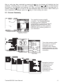
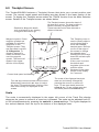
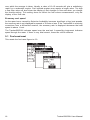
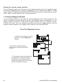
NAVMAN
Contents
1.0
Tracker500/500i Introduction ................................................................... 3
1.1
The Global Positioning System (GPS) ................................................................ 3
1.2
Commonly Used Terms ....................................................................................... 3
1.3
Operating the Tracker500/500i .......................................................................... 4
2.0
Overview .................................................................................................... 6
3.0
Man Over Board (MOB) Function .............................................................. 7
4.0
Start-up Sequence .................................................................................... 8
4.1
Satellite Status Screen ....................................................................................... 8
4.2 Acquisition Period .............................................................................................. 9
5.0
Moving Around the Screens ................................................................... 10
5.1
Menus ............................................................................................................... 10
5.2
Changing Names or Numeric Values within data fields .................................. 10
5.3
Screen Summary ............................................................................................. 11
6.0
Trackplot Screen ..................................................................................... 12
7.0
Position Screen ....................................................................................... 13
8.0
Highway Screen ...................................................................................... 14
9.0
Fuel Screen (Tracker500i only) .............................................................. 15
9.1
Fuel used reset ................................................................................................ 16
9.2
Fuel used calibration (Transducer calibration) ............................................... 17
9.3
Fuel remaining change ..................................................................................... 18
9.4
Fuel remaining low alarm ................................................................................. 18
10.0 GoTo .......................................................................................................... 19
11.0 Waypoints ................................................................................................ 20
11.1 Waypoints Screen ........................................................................................... 20
11.2 Creating Waypoints .......................................................................................... 21
Creating a New Waypoint ............................................................................. 21
Saving the current boat position ................................................................... 21
Saving the current cursor position ............................................................... 22
11.3 Viewing Waypoint Details ................................................................................ 22
11.4 Changing Waypoint Details .............................................................................. 23
11.5 Displaying a Waypoint ...................................................................................... 24
11.6 Deleting a Waypoint ......................................................................................... 24
11.7 Distance Calculations ....................................................................................... 25
Tracker500/500i User Manual
T500i/ENG/1F
1
12.0 Marks ....................................................................................................... 26
12.1 Converting Marks to Waypoints ....................................................................... 26
13.0 Routes ...................................................................................................... 27
13.1 Creating a New Route ...................................................................................... 27
13.2 Adding and Deleting Waypoints in a Route ..................................................... 28
13.3 Starting and Cancelling Routes ........................................................................ 29
13.4 Deleting a Route ............................................................................................... 30
14.0 Setup ........................................................................................................ 31
15.0 Chart Datums ........................................................................................... 33
Appendix A – Specifications ............................................................................ 36
Appendix B – Tracker500/500i Installation ..................................................... 37
Appendix C – Trouble Shooting Guide ............................................................. 39
2
Tracker500/500i User Manual
1.0 Tracker500/500i Introduction
Congratulations on purchasing a Navman Tracker500/500i track plotter. The Tracker500/
500i is a compact, ruggedly built, highly integrated navigation instrument that has been
designed for ease of use. With this instrument you will be able to display your boat’s
position, track and destination. Complex navigation functions can be performed with a few
simple key presses, taking the hard work out of navigation. Tracker500i owners have the
option of using the integrated fuel computer to keep track of their boat’s fuel usage. The fuel
computer is suitable for all petrol engine boats, either inboard or outboard, and single or
twin engine. Fuel transducers must be purchased separately.
1.1 The Global Positioning System (GPS)
The GPS constellation comprises 24 satellites orbiting the earth, providing a worldwide
system for determining position. From any one point on the earth’s surface up to 12
satellites are “visible” to the GPS receiver. The positions of these satellites are constantly
changing. The Tracker500/500i antenna tracks all visible satellites simultaneously and
selects four or more satellites that produce the optimum geometry and signal quality for
determining an accurate value of the boat’s latitude and longitude. The superior
performance achieved with the Tracker500/500i 12 channel receiver provides increased
accuracy and reduced Time to First Fix (TTFF).
Note: The USA Department of Defence introduces a varying offset,
known as Selective Availability (SA), to degrade the accuracy of the
civilian GPS signal. As an approximate guideline it is generally
assumed that the accuracy obtained with SA active causes the GPS
derived position to be within 100 metres of the true position 90% of the
time and within 50 metres of the true position 50% of the time. On brief
occasions the SA can cause the position error to exceed 300 metres.
The constantly varying SA offset causes small errors in the indicated
boat speed and heading that may be noticeable at speeds of 5 knots or
less. The position, speed and heading errors have been deliberately
designed into the system and affect all GPS receivers in the same way.
They can be eliminated by connecting a differential (DGPS) receiver to
the Tracker500/500i. This receives corrections from a fixed base
station that is able to measure the introduced SA offset.
In times of military conflict, the USA Department of Defence has been
known to turn the civilian GPS signal off. This is an extremely rare
event, but should be guarded against by always having a secondary
means of navigation to fall back on. The warning screen that appears
each time the Tracker500/500i is turned on has a reminder to this effect.
1.2 Commonly Used Terms
Waypoints Positions such as fishing spots, favourite anchorages, dive locations and trip
destinations can be saved in the Tracker500/500i memory. These are referred
to as waypoints. Up to 500 waypoints can be stored in memory. The Tracker500/
500i will automatically allocate a name to a waypoint or the user can specify a
name. Waypoints are created by saving the boat position, saving the screen
cursor position or by entering the latitude and longitude of a location.
Marks
Marks are temporary waypoints. They are created by a single press of the power
on/off key. Marks can be created at any time, regardless of the screen currently
Tracker500/500i User Manual
3
displayed. Pressing the Mark key will save the current boat position with a
temporary name in the range of MARK0 to MARK9. Marks are saved separately
from normal waypoints. They are simpler to create and display and are
intended to provide a simple method of marking temporary locations such as
fish strikes. See section 12.0 Marks for a more detailed description.
Route
Two or more waypoints can be linked in sequence to form a route. The route
has a start and end waypoint and can be traversed from start to finish or in
reverse. Up to 20 routes can be stored in memory.
Legs
Legs are the division of a route between waypoints. A route consisting of four
waypoints will have three legs.
GoTo
The Goto function allows you to navigate from your current position to any
waypoint or mark. The Tracker500/500i will guide you to your destination with
a graphical highway screen and continuously updated navigational data.
1.3 Operating the Tracker500/500i
You can use your Tracker500/500i to get you back to a good fishing spot or to sail all the way
around the world. It has been designed to be easy to use for those with no formal navigation
training, but also provides accurate navigational information for the long distance sailor. No
matter how long or short your journey, it will take you straight to where you want to go.
If your main interest is in returning to previously visited locations such as good fishing spots,
you should start by reading section 11.2 on saving the current boat position as a waypoint,
then section 10.0 on how to “goto” a waypoint. It is normally advisable to take the time to
enter a descriptive name for the waypoint as it quickly becomes difficult to remember which
is which when the number of waypoints has built up. Be sure to save the position of the
launching ramp before you start out so that you can use the Tracker500/500i to find your
way back if there is fog, rain, or it gets dark on the return journey. This also applies to any
point on your outward journey where you have to change course, such as a channel
between two islands.
Note the warning in section 1.1 on the position errors introduced by SA. If you do not have
a differential (DGPS) receiver, don’t try and navigate through narrow channels in reduced
visibility or darkness unless you have a secondary method of determining a safe course,
such as a marine chart and a depth sounder.
Working With Charts
If you want to navigate to a location that you don’t already have saved as a waypoint, you
will need to obtain its latitude and longitude from a marine chart. See section 11.2 on how
to create a new waypoint and enter Lat/Lon values. A pair of dividers is normally used to
measure latitude and longitude on a chart. To measure the latitude of a location, place one
point of the dividers on the location and then adjust the dividers until the other point is
straight above or below the first one and on the nearest horizontal grid line. Move the
dividers along the grid line to the latitude scale on the side of the chart. Put one point on
the grid line and the other on the latitude scale and read the value. It will be a number like
43°52·13´ N. A minute (´) is one sixtieth of a degree. The N indicates this location is in the
northern hemisphere. Unless you have a chart that covers a very small area, you won’t be
able to read the latitude scale more accurately than two decimal places of minutes. The
Tracker500/500i allows for three decimal places, so just put zero in the last place. The same
method is used to measure the longitude, using a vertical grid line and the longitude scale
at the top or bottom of the chart. The longitude will be a number like 010°32·95´ E. Three
4
Tracker500/500i User Manual
digits are used for the degrees as longitudes can be as large as 180°. The E indicates this
location is east of Longitude 000°, a vertical line through Greenwich (London). If you don’t
have a pair of dividers, you can use a ruler or even two pencil marks on the edge of a strip
of paper.
When entering the Lat/Lon of a waypoint from a chart, it is essential that the Tracker500/
500i is set to the same Lat/Lon datum that the chart uses (see section 15.0 Chart Datums).
This also applies if you are plotting the current boat position onto a chart. The datum will
be given in the chart’s title block.
If you use waypoints from a chart, it is a good idea to clearly mark the waypoints on the chart.
Then, before you start navigating to a waypoint, you can draw a straight line from the boat’s
current position to the waypoint and check that it doesn’t pass too close to any rocks or
shoals. A similar idea is to enter any isolated rocks in your area as waypoints with the rock
symbol ( ). When you start navigation to a waypoint, the Tracker500/500i draws a line from
the current boat position to the waypoint on its Trackplot screen. By looking at this screen
you can check whether your intended course passes too close to any isolated rocks.
Fuel Functions
The fuel computer functions available in the Tracker500i enable you to keep track of how
much fuel you have used, how much you have remaining, the rate at which fuel is being
consumed, and how far you are travelling for every litre or gallon of fuel used. All this
information is shown on one screen. The fuel used value can be cleared to zero at any time
so that you can keep track of the amount of fuel used for each trip, or for each season, or
since you bought the boat, according to your preference. The fuel remaining value, on the
other hand, must be updated each time you refuel so that you always know how much fuel
is left in the tank. There is a low fuel alarm associated with the fuel remaining value that can
be set to warn you when the fuel in the tank falls below the alarm level. You can set the
alarm level to suit the size of the boat’s engine and the distance you intend to travel.
The fuel consumption (titled FLOW on the screen) in litres or gallons per hour is shown. For
twin engine installations, the consumption for each engine is shown separately. This is
useful for checking that both engines are under the same load.
As the Tracker500i has both boat speed and fuel consumption values, it is able to calculate
the current economy rate. This is the distance the boat is travelling for every unit of fuel
used. The economy rate figure, depending on which distance unit and fuel volume unit the
Tracker500i is set to, will have units like miles per gallon or kilometres per litre. As the speed
error cause by Selective Availability becomes significant at low boat speeds, the economy
rate is not displayed for speeds of 5 knots or less. If the Tracker500i is receiving corrections
from a differential receiver, the economy rate is displayed whenever the boat speed is
above 1 knot.
Tracker500/500i User Manual
5
2.0 Overview
Display is backlit for
Night Operation
NAVMAN
Tracker500
Boat Track
Screen Cursor
Boat Symbol
Escape Key
‘Escape’ from screen or menu
Also backlighting on/off
Active Route
Power On/Off
and Marks
mark
on
Man Over Board
Reduce Trackplot Scale
zoom-in
MOB
ctr
zoom-out
Move screen cursor
and select menu
items
Increase Trackplot Scale
Centre Boat on Trackplot Screen
Power On/Off and Mark Key
The power on/off key performs a number of functions. Firstly, to switch on the
Tracker500/500i, momentarily press the Power on/off key. To switch off, press and
hold the key until the display becomes blank.
The Power on/off key also functions as the mark key. The mark key provides a quick
method of saving the current boat position. See section 12.0 Marks.
-MOB- Keys
Press the power on/off key and the zoom-in key together to activate the Man Over
Board (MOB) function. See section 3.0 Man Over Board (MOB) Function for further
details.
Escape Key
The
key is used to back out of sub screens or sub menus. When stepping through
Tracker500/500i screens you can press the
key to return to the screen previous to
the one currently displayed. Each time the
key is pressed you will ‘step back’ one
screen. The
key is also used to control backlighting level. Press and hold the
key
to automatically step through five backlight levels. Release the key when the
required backlight level is obtained.
Cursor Keys
The cursor keys control the movement of the screen cursor while in track plot mode.
Movement in eight directions is possible. The cursor keys are also used to select and
edit data such as setup information in the setup screens, waypoint data, and route
configurations. See section 5.0 for further details. In simulation mode these keys
control the simulated speed and heading.
6
Tracker500/500i User Manual
zoom-in, zoom-out keys
The Zoom In and Zoom Out functions are only active while the Track Plot screen is
displayed. The scale of the displayed track plot area can be instantly changed by
pressing the zoom-in or zoom-out key. To see more detail press the zoom-in key. To
see a larger area but less detail press the zoom-out key. When any list is displayed,
such as waypoints or datums, the zoom-in key will step down through the list a screen
at a time. The zoom-out key will step up through a list in the same manner.
-ctr- Keys
The centre function is also only active while the Track Plot screen is displayed. The
centre function positions the boat in the centre of the Trackplot screen. Momentarily
press the -ctr- keys to activate this function. This function is also an effective method
of ‘finding’ the boat when initially not displayed on the screen.
3.0 Man Over Board (MOB) Function
The MOB function allows the boat position to immediately be saved as a waypoint named
MOB, and to immediately start navigating to it. The MOB function can be activated from
any screen.
The following sequence activates this function:
1. Momentarily press the keys labelled MOB (two left most keys). The current boat
position is stored as a waypoint with the name MOB.
2. The Tracker500/500i beeps ten times to indicate that the MOB function has been
initiated.
3. A user prompt will appear asking if you are ready to start navigating to the MOB
location. This gives you the opportunity to disable the autopilot, if it is currently active.
If the autopilot is not active, press the
key to immediately start navigating to the
MOB location.
4. The display mode is automatically changed to the Highway screen, with the
Tracker500/500i navigating to the MOB waypoint.
Tracker500/500i User Manual
7
4.0 Start-up Sequence
Press the power key to switch power on.
To switch power off, press and hold the power key until the display goes blank.
Immediately after power-up the unit will display the software version number and a GPS
navigation warning.
mark
MOB
zoom-in
ctr
zoom-out
on
Press any key to proceed and start normal Tracker500/500i operation. The satellite status
screen will be displayed until the Tracker500/500i receives a valid position fix from the
key is pressed.
antenna or the
4.1 Satellite Status Screen
mark
MOB
zoom-in
ctr
zoom-out
on
During satellite acquisition the satellite status screen displays the following information.
•
The top left corner of the display indicates satellite acquisition status.
ACQ
Receiving satellite data and acquiring a position fix.
3D NAV Obtained a valid three dimensional position fix.
2D NAV Obtained a limited, two dimensional, position fix. The altitude is locked to
the last known altitude. This situation arises if the GPS receiver does not
have a clear view of the sky and is unable to track all available satellites.
8
Tracker500/500i User Manual
DIFF
Operating in differential GPS mode. Indicates that Tracker500/500i is
receiving valid RTCM 104 data and that lat/lon values provided by the
Tracker500/500i have had differential corrections applied.
Using differential GPS (DGPS) will improve receiver accuracy to 5-10 metres,
regardless of errors induced by the USA Department of Defense Selective Availability
program.
•
The top right corner indicates the geometric accuracy of the position fix. A low number
indicates a more accurate position fix.
•
The central area of the display indicates the position of each satellite. The outer circle
represents the horizon (north = top centre), while the inner circle represents 45° above
the horizon. The centre point is directly overhead. Satellites used in the current position
calculation are shown highlighted (reverse text).
•
The lower part of the display is made up of a bar graph, indicating the signal strength of
each satellite. Each of the horizontal lines is spaced 5dBHz apart with the lowest line
representing 25dBHz.
The above information will remain displayed for 5 seconds after a position fix has been
obtained. The acquisition process is fully automatic and requires no user intervention
Following the above power-up sequence the Tracker500/500i will display the main
selection screen. See section 5.0 for more details.
4.2 Acquisition Period
The time from initial power-up to the time the Tracker500/500i calculates the latitude and
longitude of the current position is known as the Time To First Fix (TTFF). The TTFF varies
in relation to a number of factors, but primarily varies due to the amount of time that has
passed since the Tracker500/500i last obtained a fix. If the Tracker500/500i has a clear view
of the sky it will typically acquire a position in 45 seconds. The TTFF may extend out to a
few minutes if the Tracker500/500i has not been used for periods longer than a few months.
If the Tracker500/500i has moved a significant distance, typically greater than 500 km,
since the last time it was used, it will automatically go into a cold start mode and “search”
the sky for satellites. This is fully automatic and requires no user intervention. In cold start
mode the TTFF may extend out to 8 minutes in the worse case. The TTFF is also influenced
by the current satellite geometry and position of the antenna. The antenna must have an
unobstructed view of the sky.
The Tracker500/500i will always do a cold start the first time it is turned on. Once it has
obtained a fix, switch to the Trackplot screen and press the -ctr- keys to initialise the
Trackplot screen boat and cursor positions.
Tracker500/500i User Manual
9
5.0 Moving Around the Screens
After the power-up sequence has completed, as described in the previous section, the Main
Selection screen will be displayed, as shown below.
All Tracker500/500i screens are accessed from this screen. Graphical screens showing boat
position and navigation data are available from this screen, along with waypoint and route
management features and instrument setup screens. The Satellite Status screen, displayed
at power-up, can also be viewed using this menu.
mark
MOB
zoom-in
ctr
zoom-out
on
5.1 Menus
The cursor keys are used to highlight menu items on screens such as the Main Selection
screen, Setup, Waypoints and Routes screens. Press the
or
key to step up/down the
menu items to highlight the item you wish to change or view. Press the
key to select the
highlighted item and move to the associated sub-screen. Press the
key to return to the
previous level.
The sub-screen selected may provide another list of related screens. The cursor keys can
then be used to select a screen from the list, stepping down to the next level. This
hierarchical approach of stepping through various levels of screens is used throughout the
Tracker500/500i. It is important to note that you are able to step back to previous screens by
pressing the
key. Each time the
key is pressed you will return to the previous screen
displayed. Eventually, by repeatedly pressing the
key, you will return to the Main
Selection screen.
5.2 Changing Names or Numeric Values within data fields
The method described above also applies when a name or multi-digit number needs to be
changed, for example waypoint names and waypoint lat/lon values. See section 11.0
Waypoints for a detailed explanation of waypoints. Once information for a particular
waypoint is displayed the
or
keys can be pressed to highlight the name or data you wish
to change (waypoint lat/lon, symbol, etc).
10
Tracker500/500i User Manual
After a value has been selected by pressing the
key, the display will highlight the first
character, indicating that you are able to change it. Press the
or
key to scroll through
the letters of the alphabet and numbers 0-9. After you have reached the required letter or
number press the
key to move to the next character within the name or data. When you
have completed all changes press the
key to finish editing the value.
5.3 Screen Summary
Two graphical screens simplify
navigation. The Trackplot Screen
provides you with a graphical
representation of your previous travel
as well as your planned route. The
Highway Screen provides graphical
birds-eye-view roadway guidance to
your destination
Trackplot Screen
Navigation Data
Highway Screen
Three data screens enable
easy access to essential
information such as
navigation data, satellite
status information, and fuel
consumption/economy/used
information.
Satellite Status
Fuel Data
Navigation functions,
waypoint and route
construction and
general setup
parameters are
accessed from five
main screens.
Tracker500/500i User Manual
11
6.0 Trackplot Screen
The Tracker500/500i features a Trackplot Screen that plots your current position and
course. The current vessel speed and heading are also shown in the lower section of the
screen. To display the Trackplot screen select the TRACK function from the Main Selection
screen. Details of the Trackplot screen are shown below.
The Trackplot screen shows the track of
the boat as it moves. The boat position is
saved in memory at regular intervals.
These intervals can be time intervals or
distance intervals.
Destination Waypoint details
such as distance to go, bearing
to waypoint and time to go.
Waypoint symbol. Seven
waypoint symbols are
available for indicating
waypoints on the
Trackplot screen. They
are described in section
11.0 Waypoints. To
display a waypoint’s
name, move the cursor
over the waypoint
symbol. The name will
appear in the upper
section of the display.
mark
Current boat speed and heading
MOB
zoom-in
on
The -ctr- keys centre the boat on the screen.
Momentarily press both -ctr- keys to centre
the boat. This method allows centring of the
boat when initially not displayed on the
screen.
ctr
zoom-out
The Trackplot cursor is
used to identify objects
on the display and to
move the viewable
trackplot area. Shift the
cursor off the edge of
the screen to change
the viewable area.
Holding the cursor keys
down will activate rapid
movement.
If the cursor is moved,
the latitude and
longitude of the cursor
position will be
displayed in the upper
section of the display
for 5 seconds.
The scale of the displayed track plot
area can be instantly changed by
pressing the zoom-in or zoom-out
keys. To see more detail press the
zoom-in key. To see a larger area but
less detail press the zoom-out key.
Scale
The scale is momentarily displayed in the upper left corner of the Track Plot display
whenever the cursor is moved or a zoom key is pressed. The scale can be adjusted from 0.1
to 500 miles/kilometres by pressing the zoom-in or zoom-out keys. The figure displayed is
the vertical distance from the top to the bottom of the displayed area.
12
Tracker500/500i User Manual
7.0 Position Screen
The Tracker500/500i’s position screen displays navigation data, speed, course, etc, along
with additional data not readily available from other screens.
The latitude and longitude of your current boat position is displayed at the top of the
display along with the chart datum currently selected.
mark
MOB
zoom-in
ctr
zoom-out
on
Tracker500/500i User Manual
13
8.0 Highway Screen
This screen provides a graphic ‘highway’ that shows your movement relative to your desired
course. The highway is drawn from your original start point to a selected destination point.
In the Highway screen the destination is positioned at the top of the display and the boat
position is automatically maintained in the central area of the display. A bird’s-eye view of
the highway is displayed on the screen. This provides a simple and effective method of
seeing exactly where you are in relation to your intended course. The width of the highway
can be set to between 0.1 and 5.0 miles or kilometres. The larger widths are mostly of
interest to sailors who may have to tack up wind towards a waypoint.
Note: With no destination (waypoint) selected, this page is of limited use.
The current speed and heading will be displayed on the lower section of
the screen, but the remainder of the page will be inactive.
The following diagram shows the information available on the Highway screen.
Bearing to
Waypoint
Destination
Waypoint Name
Distance to
Waypoint
10° Markers
Estimated Travel
Time to Waypoint
Heading Marker
(Steering Indicator)
Graphic
Highway
Destination
Waypoint Marker
Previous
Track
mark
MOB
zoom-in
ctr
Current Boat Position
Relative to Intended
Course
zoom-out
on
Boat Speed
Width of
Highway
Current Boat
Direction or Heading
Your present position relative to your intended course is shown by the diamond in the centre
of the highway. Your present heading, relative to the current direction to the waypoint, is
indicated by the cross that slides along the horizon, while the destination waypoint is
represented by the stationary box in the centre of the horizon.
If you deviate by more than 30° either side of the waypoint, the heading marker will remain
hard against the edge of the screen.
14
Tracker500/500i User Manual
9.0 Fuel Screen (Tracker500i only)
The Tracker500i has a comprehensive set of fuel management features. To utilise these
features you need only purchase a Navman fuel flow transducer. This plugs into the 5 pin
connector on the rear of the Tracker500i. For twin engine installations there is a kit
containing two fuel transducers and a ‘Y’ cable to enable both transducers to be connected
to the 5 pin connector.
The Navman fuel flow transducer has been specifically developed for use with petrol
inboard and outboard engines. It is best suited to outboards from 30 to 300hp, and inboard
engines from 45 to 450hp, but will operate outside these limits up to a maximum flow rate
of 130 litres (35 US gallons) per hour, per engine.
Running the engine without the Tracker500i turned on will result in fuel use not being
recorded. This will mean that the fuel remaining value will read higher than what is actually
in the tank. Always turn your Tracker500i on immediately after starting your engine.
To display the Fuel screen, select the FUEL function from the Main Selection screen.
Details of the Fuel screen are shown below.
The fuel used figure
indicates the volume of
fuel that the engine or
engines have consumed
in total since the figure
was last reset.
The fuel remaining
amount is reduced as
the fuel runs through
the fuel transducer(s).
Highlight this line,
to
then press
change the value or
set the low level
alarm.
Highlight this line, then
to access reset
press
and calibration functions.
This indicates the
averaged flow rate
Current boat speed
mark
MOB
zoom-in
ctr
zoom-out
The economy reading
can enable you to
see the most fuelefficient speed to
travel at. This figure
is calculated from the
speed and flow rate.
on
The units selected in the Setup screen for
distance and fuel volume will be used to display
the figures in the most useful format for you.
Flow rate averaging
An engine does not draw fuel from the tank at a steady rate. Normally it will draw fuel at a
relatively high rate for a few seconds until the carburettor bowl or fuel injection reservoir is
full, and then draw no fuel for a few seconds. If this instantaneous flow rate were displayed,
it would be too erratic to follow on screen. To improve the display, the Tracker500i averages
the fuel flow rate.
The amount of time over which the averaging is done can be changed in the Setup screen
(section 14.0 Setup). The ‘FLOW FLTR’ (flow filter) value reflects the number of seconds
Tracker500/500i User Manual
15
over which the average is taken. Usually a value of 10-15 seconds will give a satisfactory
result for a carburettor engine. Fuel injected engines may require a larger value. Too high
a flow filter value will slow down the display of real changes in flow rate when you change
the throttle setting. This setting does not affect the fuel volume measurement, only the
display of the flow rate.
Economy and speed
As the speed error caused by Selective Availability becomes significant at low boat speeds,
the economy rate is not displayed for speeds of 5 knots or less. If the Tracker500i is receiving
corrections from a differential receiver, the economy rate is displayed whenever the boat
speed is above 1 knot.
The Tracker500/500i indicates speed over the sea bed. A speed/log instrument indicates
speed through the water. If there is any tidal current, these two will be different.
9.1 Fuel used reset
This resets the fuel used figure to 0.0.
16
Tracker500/500i User Manual
9.2 Fuel used calibration (Transducer calibration)
Without calibration, accuracy can be expected to be better than 10%. By recording the
actual fuel usage of your boat over a period of time, it will be possible to adjust the
Tracker500i to give consistently accurate readings within a 2% tolerance.
In a twin engine installation you can calibrate the port and starboard transducers
independently.
To calibrate your fuel transducer you will need to accurately measure the fuel used. This is
most easily done with a small portable tank. It should be noted that, due to air pockets, it is
very difficult to fill under-floor tanks to the same level twice. At least 15 litres should be used
to ensure an accurate calibration. Each transducer in a twin engine installation must be
calibrated. This may be done at the same time with two portable tanks, or at different times
with one tank.
The procedure is as follows:
1) Reset the fuel used amount on the Tracker500i to 0.0
2) Connect the measurement tank(s) to the engine(s) via the fuel transducer(s).
3) Run the engine(s) at normal cruising speed until at least 15 litres is indicated (30 for
twin engines).
4) Check the actual amount of fuel used per engine. The easiest way to do this is to refill
the tank(s) to the original level(s) and record the value(s) shown on the fuel dispenser.
5) Select the fuel calibrate value. The amount that the Tracker500i has recorded is
displayed. Use the cursor keys to enter the actual fuel amount used. Press Esc when
the value is set. Confirm that you want to save the changes. (Repeat for other engine
in twin engine installation).
Single Engine
Twin Engine
This is an indication of the calibration factor.
It will be 1.00 as a default.
Tracker500/500i User Manual
17
9.3 Fuel remaining change
The fuel remaining value must be changed manually each time you change the amount of
fuel in the tanks (e.g. filling, swapping or syphoning tanks). If it is not, this figure will be
meaningless.
9.4 Fuel remaining low alarm
You can use this feature to warn you when your fuel remaining drops below a certain value.
The value can be set from 1-9999. When the level drops below the value set, a message box
saying “Fuel low alarm” will display, and the unit will beep until “OK” is selected. While the
remaining amount is below the alarm amount, the alarm will re-activate whenever the unit
is switched on, or the fuel remaining amount or low alarm value is changed. The fuel alarm
may be totally disabled by setting the alarm value to 0.
18
Tracker500/500i User Manual
10.0 GoTo
The GoTo function provides a simple method of navigating from the current boat position
to a waypoint or mark.
The GoTo sub-screen that can be selected from the Main
Selection screen gives the options to GoTo a waypoint or
mark, or to Go Along a route. Each of these options will
bring up the appropriate list of destinations. Selecting a
destination will start the navigation process and switch to
the Highway screen. The Tracker500/500i will display the
distance, time and bearing to the destination waypoint. It
can also guide a NMEA compatible autopilot to the
destination waypoint.
There are several other methods of activating the GoTo
function:
• From the Trackplot screen, position the cursor over a waypoint or mark. Press and hold
the zoom-out key until the waypoint or mark details are displayed. Select the GoTo
option from this screen.
mark
mob
zoom-in
ctr
zoom-out
on
• From the Waypoints or Marks sub-screens, select your destination. A waypoint or mark
details screen will be displayed. Select the GoTo option from this screen.
• From the Routes sub-screen, select the route you want to traverse. Then select the Go
Along option.
Cancel GoTo
To deactivate the GoTo function simply select STOP NAV from the Main Selection page. A
message will be displayed asking you for confirmation that you wish to stop navigating to
the current waypoint.
Tracker500/500i User Manual
19
11.0 Waypoints
The GPS receiver of the Tracker500/500i provides current position, speed and direction
information which can be viewed on the Position screen. But knowing your position is only
a small part of navigation. You also need to keep track of where you have been and where
you are going. Waypoints are electronic markers stored by the Tracker500/500i and are used
to keep track of start points, destinations, objects of interest, and any other important
position.
A waypoint is a named location with an associated latitude and longitude. You can GoTo
waypoints and include them in routes. They can be moved, deleted or renamed. A choice
of symbols are available for displaying them on the Trackplot screen.
11.1 Waypoints Screen
The Waypoints screen displays a list of waypoint functions. These functions allow you to
create a new waypoint or select an existing waypoint to examine or change. A waypoint can
be created by manually entering a lat/lon value or by saving the current boat position or
Trackplot screen cursor position.
mark
MOB
zoom-in
ctr
zoom-out
on
There are two methods of displaying the Waypoints screen.
Firstly, Waypoints can be selected from the Main Selection screen. Alternatively, a short cut
method of displaying the Waypoints screen is available. From the Trackplot screen, press
and hold the zoom-out key until the Waypoints screen is displayed.
Note: Using the short-cut method described above, the trackplot screen
cursor must not be positioned over an existing waypoint. If the Trackplot
screen cursor is positioned over an existing waypoint, the shortcut key
press will take you directly to a screen displaying the details for that
particular waypoint.
20
Tracker500/500i User Manual
11.2 Creating Waypoints
The Tracker500/500i allows you to store and use up to 500 waypoints. There are three
methods of creating waypoints as described in the following sections.
Creating a New Waypoint
You can create a new waypoint by directly entering a lat/lon value and waypoint name. To
do this you must first display the Waypoints screen. The Waypoints screen can be selected
from the Main Selection screen or entered directly from the Trackplot Screen by holding
down the zoom-out key, as described previously.
From the list displayed in the Waypoints screen, select the NEW option. A new waypoint will
be created and saved into memory, with a default lat/lon, symbol and a default name in the
range WPT00001-WPT00500. A Waypoint Details screen, as shown below, will be
displayed for the new waypoint. The options available from the screen are described later
in this section. Select EDIT to enter the required lat/lon and optionally change the name
and symbol.
mark
mob
zoom-in
ctr
zoom-out
on
Note: When a new waypoint is created the Tracker500/500i will enter
default values for the waypoint name and lat/lon. The lat/lon value will be
the position of the cursor as displayed on the Trackplot screen. For this
reason it is advisable to display the Trackplot screen and position the
cursor near the location of the new waypoint. This will simplify the
process of manually entering lat/lon values. The initial default values
will be similar to the values you require.
Saving the current boat position
From the list displayed on the Waypoints screen, select the NEW AT BOAT option. A new
waypoint will be created and saved into memory, with a default name in the range
WPT00001- WPT00500, a default symbol and the boat’s current latitude and longitude. A
Waypoint Details screen will be displayed for the new waypoint. The options available from
this screen are described later in this section. Select EDIT to change the name and/or
symbol.
Tracker500/500i User Manual
21
Saving the current cursor position
On the Trackplot screen move the cursor to the required location of the new waypoint. Press
and hold the zoom-out key to display the Waypoints screen. Selecting the NEW AT CRSR
option initiates an operation identical to NEW AT BOAT (see above), except that the current
cursor lat/lon is used instead of the current boat lat/lon.
11.3 Viewing Waypoint Details
To view waypoint details you can select an existing waypoint from the list of waypoints. This
option is available from the Waypoints screen, as described below. Alternatively, you can
display waypoint details for a particular waypoint directly from the Trackplot screen.
Position the cursor over the waypoint and press and hold the zoom-out key until the
waypoint details appear on the display. Both methods are illustrated below.
From The Waypoints Screen.
1. Use the cursor keys to choose
SELECT from the Waypoints
screen.
2. Select the required waypoint
from the list of waypoints stored in
memory
3. The waypoint name and lat/lon will
be displayed. To change waypoint
information such as name, lat/lon or
symbol, select the EDIT function from
the list of available functions.
22
Tracker500/500i User Manual
From The Trackplot Screen.
1. Use the cursor keys to
position the Trackplot cursor
over the required waypoint.
The waypoint name will
appear in the top section of
the Trackplot display.
2. Press and hold the zoom-out
key until the Waypoint Details are
displayed.
zoom-out
3. The waypoint name and
lat/lon will be displayed. To
change waypoint information
such as name, lat/lon or
symbol, select the EDIT
function from the list of
available functions.
11.4 Changing Waypoint Details
To change the lat/lon value, waypoint name or waypoint symbol, display the Waypoint Edit
screen by selecting EDIT from the Waypoint Details screen.
mark
MOB
zoom-in
ctr
zoom-out
Waypoint Symbols
on
To edit the data on this page use the cursor keys to highlight the desired item and press the
key to select it. Then use the
and
cursor keys to change the first character. These keys
are used to scroll through the letters of the Alphabet and numbers 0-9. After the changes
have been completed press the
key to move to the next character or press the
key to
Tracker500/500i User Manual
23
terminate editing of this data field. At the completion of all changes press
again and you
will be prompted with a screen asking for confirmation to save the changes to memory.
Select YES to save the changes to memory.
11.5 Displaying a Waypoint
If you are unsure of the location of an existing waypoint, you can use the Show function to
display the waypoint in the centre of the Trackplot screen. This allows you to see where it is
in relation to other waypoints and the current boat position.
1. Display the Waypoint Details
screen for the waypoint you wish
to find by selecting it from the
list of waypoints.
2. Use the cursor keys to select the
SHOW function. The Trackplot
screen will be displayed with the
waypoint located in the centre.
mark
mob
zoom-in
ctr
zoom-out
on
11.6 Deleting a Waypoint
1. To permanently delete a waypoint
from memory, display the Waypoint
Details screen for the waypoint you
wish to delete, as described in
section 11.3.
2. Use the cursor keys to select the
DELETE function. The Waypoint
will be permanently removed from
the Tracker500/500i memory.
mark
mob
zoom-in
ctr
zoom-out
on
24
Tracker500/500i User Manual
11.7 Distance Calculations
The final waypoint function available is the distance and bearing calculator. The following
diagram illustrates the method used to determine distance and bearing between waypoints.
1. Use the cursor keys to select
DISTANCE from the Waypoints
screen.
2. Select the start and end waypoints
from the list of waypoints stored in
memory
3. The Distance screen will be
displayed, showing the distance and
bearing from the start waypoint to
the end waypoint.
Tracker500/500i User Manual
25
12.0 Marks
Marks are temporary waypoints. They are saved separately from waypoints, making them
easier to find, change or delete. Marks are created by momentarily pressing the power on/
off key. This will save the current boat position with a temporary name in the range of
MARK0 to MARK9. Up to ten Marks can be saved in this manner. If more than ten Marks are
created, the oldest ones will be overwritten by the more recent ones. There is a Mark Details
screen in the same way as there is a Waypoint Details screen. The Mark Details screen can
be displayed either by positioning the cursor over the mark on the Trackplot screen and
holding down the zoom-out key, or by selecting the mark from the list displayed by the
MARKS option on the Main Selection screen.
The symbol for a Mark is:
12.1 Converting Marks to Waypoints
Marks can be converted to Waypoints by selecting the SAVE AS function from the Mark
Details screen.
From The Trackplot Screen
1. Use the cursor keys to
position the Trackplot cursor
over the required Mark. The
Mark name will appear in the
upper section of the Trackplot
display.
2. Press and hold the zoom-out
key until the Mark Details screen
is displayed.
zoom-out
3. Select SAVE AS from the
list of available functions.
4. An edit screen will be displayed, allowing
you to change the name of the waypoint and
the waypoint symbol. Use the cursor keys to
edit these.
5. Press
26
to save the changes to memory.
Tracker500/500i User Manual
13.0 Routes
A route is a sequence of waypoints that are traversed in order. A route can consist of any
number of waypoints from a minimum of two to a maximum of 20. Routes can be started
from any waypoint within the route and can be traversed in either direction.
The Routes screen can be accessed from the Main Selection screen. The Routes screen has
options for creating, editing and activating routes.
Note: While a route is active you can create new routes or edit other
existing routes in memory. However, you can not edit the current active
route or any waypoints within the active route.
13.1 Creating a New Route
A route is created by selecting the waypoints in the route from those currently in memory.
1. Use the cursor keys to
select Routes from the
Main Selection screen.
2. Select New to create a new route. A
default route name will be displayed. The
cursor will be positioned on the route
name allowing you to use the cursor keys
to change the name, if required.
Press the
key to save the route name
to memory and to continue to the next
step. A list of waypoints currently stored in
memory will be displayed.
3. To select the first waypoint in the route,
highlight it with the cursor keys and press the
key. To continue to add further waypoints to the
route see the following section titled Adding and
Deleting Waypoints in a Route.
Press
to select
waypoint
4. To exit the routes screen and save the new
route to memory, press the
key.
Creating a New Route
Tracker500/500i User Manual
27
13.2 Adding and Deleting Waypoints in a Route
Waypoints within a route can be deleted and new waypoints can be added, providing the
route is not currently active.
1. Choose Select to see
the list of routes currently
stored in memory.
2. Select the route you wish to
edit from the list.
3. Select the EDIT option.
4. The list of waypoints included in the
route will be displayed. Move the cursor
to the waypoint you wish to delete.
Alternatively, if you wish to insert a new
waypoint, move the cursor to the line
above or below the point at which you
wish to insert it. Press the cursor key
to display the possible actions.
Examples of the two possible choices:
Insert Waypoint
You have the option of
inserting the new waypoint
either above the point you
highlighted or below it.
Remove Waypoint
Adding and Deleting Waypoints in a Route
28
Tracker500/500i User Manual
13.3 Starting and Cancelling Routes
To start traversing a route, it must first be selected from the list of previously created routes.
The route can be traversed in the forward direction or in the reverse direction, allowing you
to return along the same route. You can also choose any waypoint in the route as the start
waypoint.
Note: To cancel an active route select STOP NAV from the Main
Selection screen. A message asking you to confirm that you wish to
cancel the active route will be displayed.
1. Choose Select to see the list of
routes currently stored in memory.
2. Select the route from the list.
3. Select Go Along from the list of
available functions.
4. Choose whether to traverse the
route in the forward direction or
the reverse direction.
5. The list of waypoints included in the
route will be displayed. Move the cursor
to the first waypoint you wish to head
towards. By default, the first waypoint in
the route will be highlighted. Press the
cursor key to start the route from the
highlighted waypoint.
Starting a Route
Tracker500/500i User Manual
29
13.4 Deleting a Route
The following sequence removes an existing route from memory.
1. Choose Select to see the list of
routes currently stored in memory.
2. Select the route from the list.
3. Select Delete from the list
of available functions.
4. Confirm that the route is to
be deleted.
Deleting a Route
30
Tracker500/500i User Manual
14.0 Setup
Select Setup from the Main Selection screen to access the Tracker500/500i setup functions.
See section 5.0 for a detailed description of using the cursor keys to select menu items and
changing data fields.
On the Setup screen and its sub-screens, where there is a value on the end of a highlighted
menu line, this can be changed by pressing the
or
cursor keys. The
key will step
forward through the list of available values and the
will step in the reverse direction.
TRACK
TRACK CLEAR Clears the track of the boat from the Trackplot
Screen. The Tracker500/500i will immediately start
recording a new track if Track is enabled.
TRACK ON/OFF Enable/Disable saving of boat track.
MODE
To obtain a track history, the Tracker500/500i saves
the boat position to memory at regular intervals.
These intervals can be time intervals or distance
intervals. The MODE setting allows you to select time
or distance intervals.
INTRVL
The selectable time interval range is 10 seconds to 1
hour. The selectable distance interval range is 0.1 to
5 miles/kilometres.
HIGHWAY
Highway screen road width. Range 0.1 to 5 miles/nautical miles/
kilometres.
DATUM
GPS derived positions are based on a worldwide reference (datum)
known as WGS 1984. Many charts are based on datums other than
WGS 1984. This results in an offset between a Lat/Lon plotted on the
chart and the same Lat/Lon plotted on the Tracker500/500i. To match
the Tracker500/500i with your chart you must enter the datum shown
on the chart. Alternatively, if your datum is not included in the list of
datums, you can enter an offset value to ensure the displayed lat/lon
values match the chart. Once you have entered a datum or offset
values for your chart, all latitudes and longitudes, including waypoints,
will match the chart.
USE
This option allows you to set the Tracker500/500i to
use either a datum or a position offset. The currently
selected datum and position offset values are
displayed in the bottom half of the screen. The
selected correction method has a box drawn round it.
POS.OFS. >
Position Offset edit window. Enter offset values in the
range 0.000 – 9.999 minutes.
DATUM
Select this option to choose from the list of 106
available chart datums.
Tracker500/500i User Manual
>
31
BEARINGS
The Tracker500/500i automatically calculates the magnetic variation
for the location in which it is situated. Consequently, all bearings and
course directions can be displayed either relative to true North or
magnetic North. Select TRU or MAG as required.
UNITS
The Tracker500/500i has three units of measure; Nautical miles,
Statute (land) miles and Kilometres. This setting applies to all distance
and speed readings displayed on the Tracker500/500i.
TIME
OFFSET
12/24HR
FUEL
ENGINES
VOL UNIT
FLOW FLTR
DISPLAY
This is the time offset from your time zone to
Greenwich Mean Time (GMT). Range +/- 13 hours in
steps of 30 minutes.
Sets the time display to be in either 12 hour or 24
hour format.
Choose the number of petrol engines, 1 or 2.
Select the unit of measure for volume; litres, Imperial
gallons, or U.S. gallons.
Adjust the amount of averaging of the fuel flow rate.
Range 1–60.
CONTRAST
Display Contrast. This adjustment enables you to
obtain the optimum display appearance. Set the level
for optimum display contrast. Range 0–10.
BACKLIGHT
Display backlight intensity. Range 0–15.
LANGUAGE
English, French, German, Swedish, Spanish, Dutch, Italian.
SIMULATE
Simulation mode provides a method of becoming familiar with the
Tracker500/500i functions. Boat movement is simulated and all
navigation functions are available. Setting SIMULATE to ON generates
a simulated boat with an initial position at the current position of the
Trackplot screen cursor, with zero speed and heading. To change the
speed and heading, switch to the Highway screen and use the cursor
up and down keys to change speed, and left and right to change the
boat’s heading.
32
Tracker500/500i User Manual
15.0 Chart Datums
Tanslation of Locality in the datum
table is optional but please do not
translate anything else in the table.
GPS derived positions are based on a worldwide reference (datum) known as WGS 1984.
Many charts are based on datums other than WGS 1984. This results in an offset between
a Lat/Lon plotted on the chart and the same Lat/Lon plotted on the Tracker500/500i. To
match the Tracker500/500i with your chart you must enter the datum specified on the chart.
See section 14.0 Setup for details on how to select a chart datum. Once your local datum
has been entered, all latitudes and longitudes, including waypoints, will match the chart.
Note: When using a number of charts with different datums it is important
to ensure that you change the datum to match the chart currently being
used. If the destination waypoint is on a different chart, be sure to
change to that chart’s datum before entering the latitude and longitude of
the destination waypoint.
Alternatively, you can manually enter a lat/lon offset value to bring the displayed lat/lon
values in line with the chart you are using. See the Setup screen for details on how to enter
a lat/lon offset. The lat/lon offset function is typically used to match the Tracker500/500i
with older charts where an island may have a large position error, but all points around the
island have the same error.
Tracker
abbreviation
Datum name
Datum
code
Locality
ADINAN
AFGOOYE
AINELABD 70
AMRICN SAMOA
ANNA 1 AST65
ANTIGUA
ARC 1950
Adindan
AFGOOYE
AIN EL ABD 1970
American Samoa 1962
Anna 1 Astro 1965
Antigua
ARC 1950
ADI-M
AFG
AIN-A
AMA
ANO
AIA
ARF-M
ARC 1960
ASCN IS 1958
ASTRO BCN”E”
ASTRODOS71/4
ASTR STN1952
AUST.GEO1966
AUST.GEO1984
AUST.GEO1984
BELLEVUE
BERMUDA 1957
BOGATA
CAMPO INCH
CANTON AST66
CAPE CANAV
CAPE
CARTHAGE
CHATHAM 1971
CHUA ASTRO
ARC 1960
Ascension Island 1958
Astro Beacon E
Astro DOS 71/4
Astronomic Station 1952
Australian Geodetic 1966
Australian Geodetic 1984
Ayabelle Lighthouse
Bellevue (IGN)
Bermuda 1957
Bogota Observatory
Campo Inchauspe
Canton Island 1966
Cape Canaveral
Cape Province
Carthage
Chatham 1971
Chua Astro
ARS-M
ASC
ATF
SHB
ASQ
AUA
AUG
PHA
IBE
BER
BOO
CAI
CAO
CAC
CAP
CGE
CHI
CHU
Ethiopia, Sudan
Somalia
Bahrain Island
American Samoa Islands
Cocos Islands
Leeward Islands
Botswana, Lesotho, Malawi, Swaziland, Zaire,
Zambia, Zimbabwe
Kenya, Tanzania
Atlantic Ocean
Iwo Jima
St. Helena Island
Marcus Island
Australia and Tasmania
Australia and Tasmania
Djibouti
Efate & Erromango Islands (Vanuatu)
Bermuda Islands
Colombia
Argentina
Phoenix Islands
Florida, Bahamas
South Africa
Tunisia
New Zealand
Paraguay
Tracker500/500i User Manual
33
Tracker
abbreviation
Datum name
Datum
code
Locality
CORREGO ALEG
DJAKARTA
DOS 1968
EASTER IS 67
EURO 1950
EURO 50 ENGL
Corrego Alegre
Djakarta (Batavia)
DOS 1968
Easter Island 1967
European 1950
European 1950 England
COA
BAT
GIZ
EAS
EUR-M
EUR-G
Brazil
Sumatra (Indonesia)
Gizo Island (New Georgia Islands)
Easter Island
EURO 50 WEST
EURO 1979
GAN 1970
GEO DAT 1949
GRACIOSA1948
GUAM 1963
GUX 1 ASTRO
HJORSEY 1955
HONG KONG 63
HU-TZU-SHAN
IND BNGLDSH
INDIAN 1975
INDONESIA 74
IRELAND 1965
ISTS 073ASTR
JOHNSTON IS
KANDAWALA
KERGUELEN IS
KERTAU 1948
KUSAIE ASTRO
L.C.5 ASTRO
LIBERIA 1964
LUZON PHILIP
LUZON MINDAN
MAHE 1971
MASSAWA
MERCHICH
MIDWAY AST61
MINNA NIG
NHRWN MASI
NHRWN SAUDI
NHRWN U.A.E.
NAPARIMABWI
NAD27 ALASKA
NAD27 BAHAMA
NAD27 CANADA
NAD27 CANALZ
NAD27 CARIBN
European 1950 Western
European 1979
GAN 1970
Geodetic Datum 1949
Graciosa Base SW 1948
Guam 1963
GUX 1 Astro
Hjorsey 1955
Hong Kong 1963
HU-TZU-SHAN
Indian
Indian 1975
INDONESIA 74
Ireland 1965
ISTS 073 Astro 1969
Johnston Island 1961
Kandawala
Kerguelen Island
Kertau 1948
Kusaie Astro 1951
L.C. 5 Astro
Liberia 1964
Luzon
Luzon Mindanao Island
Mahe 1971
Massawa
Merchich
Midway Astro 1961
Minna
Nahrwan
Nahrwan
Nahrwan
Naparima, BWI
North American 1927 Alaska
North American 1927 Bahamas
North American 1927 Canada
North American 1927 Canal Zone
North American 1927 Caribbean
EUR-A
EUS
GAA
GEO
GRA
GUA
DOB
HJO
HKD
HTN
IND-B
INH-A
IDN
IRL
IST
JOH
KAN
KEG
KEA
KUS
LCF
LIB
LUZ-A
LUZ-B
MIK
MAS
MER
MID
MIN-B
NAH-A
NAH-C
NAH-B
NAP
NAS-D
NAS-Q
NAS-E
NAS-O
NAS-P
34
England, Channel Islands, Scotland, Shetland
Islands
Austria, Denmark, France, Netherlands, Switzerland
Republic of Maldives
New Zealand
Faial, Graciosa, Pico, Sao Jorge, Azores
Guam
Guadalcanal Island
Iceland
Hong Kong
Taiwan
Bangladesh
Thailand
Indonesia
Ireland
Diego Carcia
Johnston Island
Sri Lanka
Kerguelen Island
West Malaysia, Singapore
Caroline Islands, Federated States of Micronesia
Cayman Brac Island
Africa
Phillipines (excluding Mindanao Island)
Mindanao Island
Mahe Island
Ethiopia
Morroco
Midway Islands
Nigeria
Masirah Island (Oman)
Saudia Arabia
United Arab Emirates
Trinidad & Tobago
Excluding Aleutian Islands
Excluding San Salvador Island
Tracker500/500i User Manual
Tracker
abbreviation
Datum name
Datum
code
Locality
NAD27 CENTRL
North American 1927 Central America
NAS-N
Belize, Costa Rica, El Salvador, Guatemala,
Honduras, Nicaragua
NAD27 CONUS
NAD27 CUBA
NAD27 GREEN
NAD27 MEXICO
NAD27 SANSAL
NAD83
NTH SAHARA59
OBSERV 1966
OLD EGYPT”07
OLD HAWAIIAN
OMAN
ORD SRVY GB
North American 1927 Conus
North American 1927 Cuba
North American 1927 Greenland
North American 1927 Mexico
North American 1927 San Salvador Island
North American 1983
North Sahara 1959
Observatorio 1966
Old Egyptian 1907
Old Hawaiian
Oman
Ordinance Survey of Great Britain
NAS-C
NAS-T
NAS-U
NAS-L
NAS-R
NAR
NSD
FLO
OEG
OHA-M
FAH
OGB-M
PICODELASNV
PITCAIRN1967
PORTO SANTO
PROV S AM 56
Pico de las Nieves
Pitcairn Astro 1967
Porto Santo 1936
Provisional South American 1956
PLN
PIT
POS
PRP-M
PROV S CH 63
PUERTO RICO
QATAR NAT
QORNOQ
REUNION
ROME 1940
SANTO DOS
SAO BRAZ
SAPP.HILL 43
SCHWARZECK
S AMERICA 69
SOUTH ASIA
TIMBALAI1948
TOKYO
TRISTAN 1968
VIT LEVU1916
WAKE IS ASTR
WAKE-ENIWET
WGS84
ZANDERIJ
Provisional South Chilean 1963
Puerto Rico
Qatar National
Qornoq
Reunion
Rome 1940
Santo (DOS)
Sao Braz
Sapper Hill 1943
Schwarzeck
South American 1969
South Asia
Timbalai 1948
Tokyo
Tristan Astro 1968
Viti Levu 1916
Wake Island Astro 1952
Wake-Eniwetok 1960
WGS-84
Zanderij
HIT
PUR
FAH
QUO
REU
MOD
SAE
SAO
SAP
SCK
SAN-M
SOA
TIL
TOY-M
TDC
MVS
WAK
ENW
Algeria
Corvo and Flores Islands (Azores)
Egypt
Hawaii
Oman
England, Isle of Man, Scotland, Shetland Islands,
Wales
Canary Islands
Pitcairn Island
Porto Santo & Madeira Islands
Bolivia, Chile, Colombia, Ecuador, Guyana, Peru,
Venezuela
Southern Chile
Puerto Rico, Virgin Islands
Qatar
South Greenland
Mascarene Islands
Sardinia (Sardegna Island)
Espirito Santo Island
Sao Miguel, Santa Maria Islands (Azores)
East Falkland Island
Namibia
Argentina, Bolivia, Brazil, Chile
Singapore
Brunei, East Malaysia
Japan, Okinawa, South Korea
Tristan da Cunha
Viti Levu Island (Fiji Islands)
Wake Atoll
Marshall Island
ZAN
Suriname
Tracker500/500i User Manual
(Hayes Peninsula)
35
Appendix A – Specifications
Tracker500 and Tracker500i
• Dimensions
500 132mm W x 133mm H x 46mm D.
500i 132mm W x 133mm H x 88mm D.
• Display Type
STN temperature compensated LCD.
• Display Matrix
100 x 64 Pixels.
• Input Voltage
11 to 16.6 Volts DC.
• Backlighting
15 levels plus off, 5 levels directly available
key.
from
• Operating Temperature
0 °C to 50 °C ambient (32 °F to 122 °F).
• Display Scales
Distance - 0.1 to 500 nautical miles/miles/
kilometres.
• Waypoints
500 plus 10 marks.
• Routes
20 reversable of up to 20 waypoints each.
• Chart Datums
106 Datums plus User Adjustable Offset.
• Navigation Method
Rumb line with perpendicular finishing line
termination.
Maximum Latitude: 75° N or S.
• NMEA0183 V2.1 Output
APB, BWR, GLL, RMC, VTG, XTE.
• DGPS Input
RTCM 104, 9600 baud, NMEA 0183 or
RS232 signal levels.
• Power Use (Tracker500i and Tracker500
including external antenna)
100mA Typical (Backlight off), 125mA
(Backlight on), plus 25mA per fuel
transducer.
• Languages
English, French, German, Swedish, Spanish,
Dutch, Italian.
Tracker500i Fuel Functions
• Volume Units
Litres, Imperial gallons or US gallons.
• Engine Types
Outboard petrol engines 30 to 300hp.
Inboard petrol engines 45 to 450hp.
• Number of Engines
One or two.
• Maximum Fuel Flow Rate
130 litres per hour (35 US gallons per hour)
per engine.
36
• Fuel Used and Fuel Remaining
Indication
0.0 to 9999.9 litres or gallons.
• Fuel Flow Rate Indication
0.0 to 130.0 litres per hour, 0.0 to 35.0 US
gallons per hour.
• Econommy Rate Indication
0.00 to 99.99 distance units per volume unit.
Tracker500/500i User Manual
Appendix B – Tracker500/500i Installation
Packing List
• GPS Tracker500/500i Display Head, including 2 mounting knobs & 2 washers
• Power/data cable
• Mounting Bracket
• User’s manual
• GPS Antenna, Tracker500 only
• GPS Antenna User’s Manual, Tracker500 only
Mounting
Choose a location for the display head that provides good visibility and protects the unit
from direct sun and excessive exposure to water.
Select a position that is:
• At least 300mm from a compass
• At least 300mm from any radio
• At least 1.5m from any radio antenna
• Easy to read by the helmsman and crew
• Protected from physical damage
• Accessible for electrical cable connections
• Tracker500i - Must have a clear view of the sky, but can “see” through glass, perspex,
fibreglass and fabric.
Once a location is selected secure the mounting bracket with the screws provided in the
mounting kit.
Tracker500/500i User Manual
37
Power Cable Connections
1. Connect the red wire to the positive
supply (11-16.6 VDC) via a 1 amp fuse or 1
amp circuit breaker. Connect the cable
shield to the negative supply. If possible,
route the antenna and power cable away
from other wiring on the boat. Electrical
noise from engine wiring, bilge pumps and
other equipment can affect the display.
For a detailed description of the
antenna installation procedure see the
separate installation guide supplied
with the antenna. Tracker500 only
2. Insert the display head, rubber washers
and mounting knobs in to the mounting
bracket. The rubber washers are located
between the bracket and the case of the
display head. See diagram.
Power/Data Cable Connections
(Green)
(Shield
& Brown)
(Red)
2
3
1
4
(White)
NMEA Output
(Brown)
RTCM 104 input
9600 baud
(Green)
Five Pin Connector
For a Tracker500, the five pin connector is
used for the external antenna.
For a Tracker500i, the five pin connector is
used for the fuel transducer. A twin engine
fuel kit contains a ‘Y’ cable to allow two fuel
transducers to be connected.
38
+(a)
(White)
-(b)
Autopilot
or
Repeater
+(a)
Differential
Receiver
-(b)
RED
1 amp fuse
+
SHIELD
12VDC
Tracker500/500i User Manual
Appendix C – Trouble Shooting Guide
PROBLEM
CAUSE – SOLUTION
Tracker500/500i will not switch on.
Power/data cable not connected or not not fully
connected into its socket.
Power supply connections reversed.
Tracker500/500i switches itself off.
Check for a poor connection in the power cable
causing intermittant loss of power.
When the Tracker500/500i detects a large supply
voltage surge, it will turn itself off to protect itself.
Check for loose battery connections.
Some previously available
navigation functions are no longer
available. ‘GPS FIX LOST’
message displayed.
GPS no longer has a fix. This may occur occasionally if the antenna does not have a clear view of the
sky. The satellite positions are constantly changing
so that their signals can come from any direction. It
is essential that the antenna has a clear view of the
sky.
Prolonged period to obtain a fix.
This will occur if theTracker500/500i has been
moved more than 500 kilometres since it was last
switched on, or if it has not been used for several
months. The Tracker500/500i will automatically
‘search’ the sky for all available satellites. this may
take a few minutes. This function is fully automatic
and requires no user intervention. Subsequent
times to first fix should typically be 45 seconds.
Position indicated on Tracker500/
500i varies by up to 100 metres
from true position.
The USA Department of Defence introduce a
varying offset known as Selective Availability (SA).
The direction and magnitude of the offset is
constantly varying. SA will cause errors typically of
0-100 metres, but can occasionally cause errors in
excess of 300 metres. The effects of SA can be
reduced with the installation of a differential
receiver, if this service is available in your area.
Indicated speed does not match
the boat’s speed/log instrument.
The constantly changing SA offset results in an
indicated speed error that is normally less than 1
knot, but occasionally exceeds 1.5 knots. A
Tracker500/500i connected to a differential receiver
will not exhibit this error.
The Tracker500/500i indicates speed over the sea
bed. A speed/log instrument indicates speed
through the water. If there is any tidal current, these
two will be different.
Speed/log instruments are often not calibrated
accurately and do not accurately show the boat’s
speed.
Tracker500/500i User Manual
39
Indicated heading does not
match the boat’s compass.
The boat must be moving before the Tracker500/
500i can determine its direction.
The Tracker500/500i BEARINGS setting must be
set to MAG before the indicated heading will match
the compass.
The constantly changing SA offset results in an
indicated heading error, usually apparent only at
low speeds.
The Tracker500/500i indicates the boat’s direction
of movement over the sea bed. External influences
such as tidal currents and wind induced leeway
mean that this may not be the same direction that
the boat is pointing in, which is what a compass
indicates.
Magnetic materials on the boat may influence a
compass but not a Tracker500/500i.
No/low fuel flow indicated.
Check that the 5 pin fuel transducer connector is
fully inserted into its socket on the back of the
Tracker500i.
Check that the fuel filter(s) in the line are clean.
Ensure that the fuel flow transducer has not been
exposed to excessive heat or vibration.
Only one flow rate value shown
for a twin engine installation.
In the Fuel sub-screen under Setup you must have
ENGINES set to two.
Erratic fuel flow readings.
The mounting position of the fuel flow transducer
must not be too close to the fuel pump(s) and not
subject to excess vibration.
Check for air leaks in the fuel hose(s) or fuel pickup(s) in the tank(s).
The filtering level (averaging) has not been set to
suit the engine(s). In the Fuel sub-screen under
Setup, increase the FLOW FLTR value until a
steady flow rate is indicated.
No fuel economy reading.
Check the fuel flow readings are not zero.
For the Tracker500i to be able to calculate an
economy reading, the boat must be travelling
above 5 knots, or above 1 knot if a differential
receiver is in use.
Fuel Remaining does not match
the amount left in the tank.
Fuel Remaining must be set to the amount of fuel
on board after every refueling.
Engine has been run without the Tracker500i
turned on to record the fuel usage.
Fuel transducer calibration is required when the
Tracker500i is first installed.
Also check all other fuel problems listed here.
40
Tracker500/500i User Manual
1950601B