1
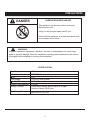
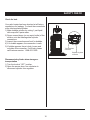
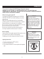
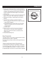
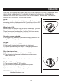
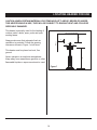
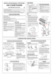
02/25/2011
Tabletop Patio
Heater
DANGER
If you smell gas:
1. Shut off gas to the appliance.
2. Extinguish any open flame.
3. If odor continues, keep away from
the appliance and immediately call
your gas supplier or fire department.
WARNING
Do not store or use gasoline or
other flammable vapors and liquids
in the vicinity of this or any other
appliance.
An LP-cylinder not connected for use
shall not be stored in the vicinity of
this or any other appliance.
WARNING
For Outdoor Use Only.
CAUTION:
Installer: Leave the manual instructions
to the user for future use.
Consumer: Please keep this manual
for future reference.
Model#: SRPT03-XXXX
Read the instructions before use.
This appliance must be installed in
accordance with such regulations as
are in force.
Standard: ANSI Z83.26-2007 / CSA 2.37-2007 ANSI Z83.26a-2008 / CSA 2.37a-2008
Gas-Fired Outdoor Infrared Patio Heaters.
Owner’s Manual
Questions, problems, missing / replacement parts? Before returning to your retailer,
call our customer service department at 1-866-814-0585, 8 a.m.-5 p.m., EST,
Monday-Friday.
PRECAUTIONS
DANGER
CARBON MONOXIDE HAZARD
This appliance can produce carbon monoxide
which has no odor.
Using it in an enclosed space can kill you.
Never use this appliance in an enclosed space such
as a camper, tent or home.
WARNING:
Improper installation, adjustment, alteration, services or maintenance can cause injury,
death or property damage. Read the installation, operating and maintenance instructions
thoroughly before installing or servicing this equipment.
SPECIFICATION
Certification
CSA
Rated Heat Input
Fuel
Gas Supply
Manifold Pressure
Injector Size(diameter)
Safety Features
10000BTU/hr
LPG
16.4oz LP-Gas cylinder
11.0" W.C.
0.91mm
Flame failure device, anti-tilt switch & Oxygen
Depletion Safety (ODS) pilot
Gas Supply Pressure
Max 250PSI, min 5PSI
2
PRECAUTIONS
NOTE:PLEASE READ THE FOLLOWING SAFETY RULES
WARNING:
Installation and repair should be done by
a qualified service person. The heater
should be inspected before use and at
least annually by a qualified service
person.
The installation must conform with local codes
or, in the absence of local codes, with the
National Fuel Gas Code, ANSI Z223.1/NFPA 54,
NFPA58 Natural Gas and Propane Installation
Code, CSA B149.1, or Propane Storage and
Handling Code, B149.2
More frequent cleaning may be required
as necessary. It is imperative that control
compartment, burners and circulating air
passageways of the heater be kept clean.
The heater, when installed, must be electrically
grounded in accordance with local codes or, in
the absence of local codes, with the National
Electrical Code, ANSI/NFPA 70, or the Canadian
Electrical Code, CSA C22.1.
Prior to use, check for damaged parts such as
tube, regulator, pilot or burner.
Keeping the appliance area clear and free from
combustible materials, gasoline and other flammable vapors and liquids.
All leak tests should be done with a soapy solution. NEVER USE AN OPEN FLAME TO
CHECK FOR LEAKAGE.
Not obstructing the flow of combustion and ventilation air.
Keeping the ventilation opening(s) of the cylinder enclosure free and clear from debris.
Children and adults should be alerted to
the hazards of high surface temperatures
and should stay away to avoid burns or
clothing ignition.
This appliance shall be used only in a wellventilated space and shall not be used in a building, garage or any other enclosed area.
Young children should be carefully
supervised when they are in the area of
the heater.
An appliance may be installed with shelter no
more inclusive than:
With walls on all sides, but with no overhead
cover.
Within a partial enclosure which includes an
overhead cover and no more than two side
walls. These side walls may be parallel, as in a
breezeway, or at right angles to each other.
Clothing or other flammable materials
should not be hung from the heater, or
placed on or near the heater.
Any guard or other protective device
removed for servicing the heater must be
replaced prior to operating the heater.
3
PRECAUTIONS
NOTE:PLEASE READ THE FOLLOWING SAFETY RULES
WARNING:
Within a partial enclosure which includes an
overhead cover and three side walls, as long as
30 percent or more of the horizontal periphery of
the enclosure is permanently open.
Do not store a spare LP-gas cylinder under or
near this appliance;
This appliance requires 16.4oz (1lb) LP_gas
supply cylinder.
Do not clean the heater with cleaners that are
combustible or corrosive.
Never fill the cylinder beyond 80 percent full;
The LP-gas supply cylinder to be used must be:
Constructed and marked in accordance with the
Specifications for LP-gas cylinders of the U.S.
Department of Transportation (DOT); or the
Standard for Cylinders, Spheres and Tubes for
Transportation of Dangerous Goods and Commission, CAN/CSA-B339, as applicable;
Place the dust cap on the cylinder valve outlet
whenever the cylinder is not in use. Only install
the type of dust cap on the cylinder valve that is
provided with the cylinder valve. Other types of
caps or plugs may result in leakage of propane.
Provided with a listed overfilling prevention
device; and provided with a cylinder connection
device compatible with the connection for the
appliance.
The cylinder be disconnected when the appliance is not is use.
Storage of an appliance indoors is permissible
only if the cylinder is disconnected and removed
from the appliance.
A cylinder must be stored outdoors in a wellventilated area out of the reach of children. A
disconnected cylinder must have dust caps
tightly installed and must not be stored in a building, garage or any other enclosed area.
4
WARNINGS AND CAUTIONS
NOTE: PLEASE READ THE FOLLOWING SAFETY RULES:
35(&$87,216
Perform a leak test with a soapy solution:
1. To check gas connections.
2. After connecting a new cylinder.
3. Upon re-assembly after disassembly.
This heater is designed to operate with a standard 1 Ib propane cylinder with Approved Cylinder
Connection.
PREPARATION
Before beginning assembly of product, make sure all parts are present. If any part is missing or
damaged, do not attempt to assemble the product. Contact customer service for replacement parts.
TOOLS NEEDED: (NOT INCLUDED)
Adjustable open end wrench
Philips screwdriver
Estimated time for assembly: 15 minutes.
5
PARTS LIST
Please check the contents of the packaging as to whether anything is missing!
1
8
1 Base
7
2
1 Housing
3
1 Burner Column
4
2 Emitter Screen Shield
5
1 Emitter Screen
6
1 Reflector Dome
11
12
12
9
7
1 Dome Cap
8
1 Decorative Dome Cap Nut
9
7 M4 x 8 Bolts
10
7 M4 x 6 Bolts
9
13
11
3
3 M6 Nuts
12
6 6mm Washers
13
1 Regulator
The fastenersused comply with ANSI/BL.1
10
6
ASSEMBLY
WARNING : ONLY AN AUTHORIZED GAS TECHNICIAN SHOULD INSTALL THIS PRODUCT.
Step 1
Step 1
Attach housing (2) to base (1) using seven
M4 x 6 bolts (10).
2
1
10
Hardware Used
10
Step 2
M4 x 6 bolt
Step 2
3
Insert the three clamps of the burner column (3)
into the three spring pieces of the housing (2)
per the picture and screw over. Make sure the
clamp and the spring piece fit together.
2
7
X7
ASSEMBLY
Step 3
Step 2
Attach emitter screen (5) to burner column (3)
using three M4 x 8 bolts (9)
Note: The ignition hole on emitter screen must
line to the control knob.
Ignition
Hole
9
ODS Hole
3
Hardware Used
9
Step 4
M4 x 8 bolt
X3
Step 4
8
Attach reflector dome (6) to emitter screen (5)
using six 6mm washers (12) and three M6 nuts
(11).
7
11
12
Then attach dome cap (7) and decorative dome
cap nut (8) to reflector dome (6).
12
5
Hardware Used
11
3
12
8
M6 nut
X3
6mm Washer
X6
ASSEMBLY
Step 5
Step 5
Attach emitter screen shield (4) to burner
column (3) using four M4 x 8 bolts (9).
4
4
4
3
9
3
4
Hardware Used
9
M4 x 8 bolt
X4
Step 6
Step 6
Open the access door. Open up the gas bottle
cover. Attach it to the regulator.
Aim at the screw thread. Turn counter clockwise
and tighten.
Regulator
Tighten
Gas bottle
9
SAFETY CHECK
Check for leak
Your patio heater has been checked at all factory
connections for leakage. To check the connections
at the tube/regulator/cylinder.
1) Make leakage solution by mixing 1 part liquid
dish soap and 3 parts water.
2) Spoon several drops (or use squirt bottle) of the
solution onto the tube/regulator/cylinder
connections.
3) Inspect the connections and look for bubbles.
4) If no bubble appears, the connection is safe.
5) If bubble appears, there is leak; loosen and
re-tighten this connection. If still leak, please
call customer service: 1-888-831-1899.
Tube & regulator
connection
Regulator & cylinder
connection
Disconnected cylinder when storage or
transportation
1) Turn the knob at “OFF” position.
2) Open the access door, turn clockwise to
disconnect cylinder from regulator.
10
OPERATION
This product is equipped with ODS (Oxygen Deprivation System)
WARNING: DO NOT ATTEMPT TO OPERATE HEATER UNTIL YOU HAVE READ AND
UNDERSTAND ALL PRECAUTION . FAILURE TO DO SO CAN RESULT IN SERIOUS PERSONAL
INJURY, DEATH, OR PROPERTY DAMAGE.
Before turning gas supply ON
Your heater was designed and approved for OUTDOOR
USE ONLY. DO NOT use it inside a building or any other
enclosed area.
Make sure surrounding areas are free of combustible
materials, gasoline, and other flammable vapors or liquids.
Ensure that there is no obstruction to air ventilation.
Be sure all gas connections are tight and there are no leaks.
Be sure the access panel is clear of debris.
Be sure any component removed during assembly or
servicing is replaced and fastened prior to starting.
Before Lighting
Heater should be thoroughly inspected before each use, and
by a qualified service person at least annually.
If relighting a hot heater, always wait at least 5 minutes.
WARNING
FOR YOUR SAFETY:
If at any time you are unable to
light burner and smell gas, wait 5
minutes to allow gas to dissipate
before attempting to light heater.
If after 1 minute, you are unable
to light burner, wait 5 minutes
and allow flammable vapors to
dissipate before attempting to
light heater.
WARNING
FOR YOUR SAFETY:
DO NOT touch or move heater
for at least 45 minutes after use.
Allow emitter and dome to cool
before touching.
Lighting instructions
1. Turn the control knob to "OFF" position.
2. Open base assembly door.
3. Turn counter-clockwise to connect cylinder with regulator
inlet.
11
OPERATION
4Push in gas control knob and turn counter clockwise to
"IGNITE" then to "PILOT" position, this will light the pilot.
If needed, keep depressing and turning control knob
counter clockwise until the pilot lights. (You will hear 1
clicking noise)
5. Once the pilot is lit, keep the control knob depressed for
approx. 30 seconds. Then release the control knob.
6. If pilot does not stay lit, repeat steps 3 and 4 after 5
minutes.
7. If pilot still does not stay lit, proceed as follows:
a) Push in gas control knob and turn counter clockwise
to the “PILOT” position.
b) Keep depressing the control knob, put a long stem
lighter into the ignition hole on the emitter screen.
To light the pilot.
c) Repeat step 5.
8. Push in and turn control knob counter clockwise to
“HIGH” position, if you want a lower temperature,
push in the control knob and turn clockwise to the
“LOW” position.
9. Close base assembly door.
Flame Characteristic
The flame pattern at the emitter screen should be visually
checked whenever heater is operated.
Normally the burner flame is blue, but little yellow flame is
acceptable.
If flames extend beyond surface of the emitter grid ,
or the phenomena of flame lift or light back, or black spot
is accumulating on the emitter grid or reflector, the heater
should be turned off immediately. The heater should not
be operated again until the unit is serviced and or repaired.
12
OPERATION
CAUTION : AVOID INHALING FUMES EMITTED FROM THE HEATER'S FIRST USE. SMOKE AND
ODOR FROM THE BURNING OF OILS USED IN MANUFACTURING WILL APPEAR. BOTH
SMOKE AND ODOR WILL DISSIPATE AFTER APPROXIMATELY 30 MINUTES. THE HEATER
SHOULD NOT PRODUCE THICK BLACK SMOKE.
NOTE:
The burner may be noisy when initially turned on. To eliminate
excessive noise from the burner, turn the Control Knob to the "LOW"
position. Then, turn the knob to the level of heater desired.
When heater is ON:
Emitter screen will become bright red due to intense heat. The color
is more visible at night. Burner will display tongues of blue flame.
These flames should not be yellow or produce thick black smoke,
indicating an obstruction of airflow through the burners.
Operation pressure checked:
If the flame is very small, this is because the supply pressure is not
enough. Please refill gas cylinder.
Re-light:
1) Turn the control knob to "OFF" position.
2) Wait five (5) minutes before attempting to relight pilot.
3) Repeat steps beginning with step 4 of the lighting instruction
above.
Shut down instructions:
1) Push in and turn control knob clockwise to "OFF" position.
2) Turn clockwise to disconnect cylinder from regulator when
heater is not in use.
Note: After use, some discoloration of the emitter screen is normal.
The Event of Gas Leakage:
1) Turn the control knob to "OFF" position.
2) Turn clockwise to disconnect cylinder from regulator.
3) Wait 5 minutes to allow gas to dissipate.
4) If odor continues, immediately call gas supplier.
WARNING : Heater will be hot after use.
Handle with extreme care.
13
LOCATING HEADER FOR USE
CAUTION: WHEN CERTAIN MATERIALS OR ITEMS ARE LEFT, ABOVE, BESIDE OR UNDER
THIS HEATER WHILE IN USE, THEY WILL BE SUBJECT TO RADIANT HEAT AND COULD BE
SERIOUSLY DAMAGED.
This heater is primarily used for the heating of
outdoor patios, decks, spas, pools and open
working areas.
CEILING/OVERHANG
12"
10"
WALL
Always make sure that adequate fresh air
ventilation is provided. Follow the spacing
tolerances shown in Figure 1 at all times.
This heater must be placed on level, firm
ground.
Never operate in an explosive atmosphere.
Keep away from areas where gasoline or other
flammable liquids or vapors are stored or used.
30"
Figure 1
14
MAINTENANCE/STORAGE
CLEANING AND MAINTENANCE :
To enjoy years of outstanding performance from your
heater make sure you perform the following maintenance
activities on a regular basis:
Keep exterior surfaces clean.
Yellow Tip
Primarily Blue
Flame
Use warm soapy water for cleaning. Never use
flammable of corrosive cleaning agents.
While washing your unit, be sure to keep the area
around the burner and pilot assembly dry at all times. If
the gas control is exposed to water in any way, do NOT
try to use it. It must be replaced.
Keep the appliance area free and clean from
combustible materials, gasoline or other flammable
vapors an liquids.
Visually check buner flames.
At least once a year, the unit should be inspected for
the presence of spiders, spider webs or other insects.
Air flow must be unobstructed. Keep controls, burner,
and circulating air passageways clean. Signs of possible
blockage include:
Gas odor with extreme yellow tipping of flame.
Heater does NOT reach the desired temperature.
Heater glow is excessively uneven.
Heater makes popping noises.
Spiders and insects can nest in burner or orifices. This
dangerous condition can damage heater and render it
unsafe for use. Clean burner holes by using a heavy-duty
pipe cleaner. Compressed air may help clear away
smaller particles.
Carbon deposits may create a fire hazard. Clean dome
and engine with warm soapy water if any carbon
deposits develop.
15
WARNING:
FOR YOUR SAFETY ;
DO NOT touch or move heater for
at least 45 minutes after use. Allow
all burner elements to cool before
touching.
NOTE:
In a salt-air environment (such as
near an ocean). corrosion occurs
more quickly than normal.
Frequently check for corroded
areas and repair them promptly.
NOTE:
wait until heater is cool before
covering.
MAINTENANCE/STORAGE
STORAGE:
NOTE:
wait until heater is cool before
covering.
Between uses:
Turn the control knob to "OFF" position.
Turn clockwise to disconnect cylinder from regulator.
Store heater upright in an area sheltered from direct
contact with inclement weather (such as rain, sleet, hail,
snow, dust and debris).
If desired, cover heater to protect exterior surfaces and
to help prevent build up in air passages.
During periods of extended inactivity or when
transporting;
Turn the control knob to "OFF" position.
Disconnect the cylinder from the regulator by turning
clockwise and move to a secure, well-ventilated
location outdoors. DO NOT store in a location that will
exceed 125 degrees F.
Store heater upright in an area sheltered from direct
contact with inclement weather (such as rain, sleet, hail,
snow, dust and debris).
If desired, cover heater to protect exterior surfaces and to
help prevent build up in air passages.
16
TROUBLESHOOTING
PROBLEM
PROBABLE CAUSE
SOLUTION
Pilot will not light
Gas valve may be OFF
Turn the gas valve ON
Tank fuel empty
Refill LP gas tank
Air in supply system
Purge air from lines
Loose connection
Check all fittings
Debris around pilot
Clean dirty area
Loose connection
Tighten connection
Thermocouple
Contact customer service
Gas leak in line
Check connections
Lack of fuel pressure
Fuel tank is near empty
Pressure is low
Fuel tank is near empty
Control valve not ON
Turn valve to ON
Thermocouple broken
Contact customer service
Pilot light assembly bent or
not in correct location
Contact customer service
Pilot will not stay on
Burner will not light
17
ONE-YEAR LIMITED WARRANTY
The appliance has been manufactured under the highest standards of quality and workmanship. We
warrant to the original consumer purchaser that all aspects of this product will be free of defects in
material and workmanship for one (1) year from the date of purchase. A replacement for any defective
part will be supplied free of charge for installation by the consumer. Defects or damage caused by the
use of other than genuine parts are not covered by this warranty. This warranty shall be effective from
the date of purchase as shown in the purchaser’s receipt.
This warranty is valid for the original consumer purchaser only and excludes industrial, commercial or
business use of the product, product damage due to shipment or failure which results from alteration,
product abuse, or product misuse, whether performed by a contractor, service company, or consumer.
We will not be responsible for labor charges and/or damage incurred in installation, repair or replacement, nor for incidental or consequential damage.
NAC Customer Care
214 Bayview Drive
Barrie, ON
Canada, L4N 4Y8
1-866-820-8686
1-705-727-4282 (fax)
[email protected]
This warranty may give you specific legal rights that vary by state or province.
18
SRPT03-XXXX
color
material & base
venthole shape
reflector
venthole shape
reflector
1. 1PC reflector
2. 2PCS reflector
3. 3PCS reflector
ʅ
ʅ
ʅ
material & base
1. Round
ʅ
ʅ
ʅ
2. Rhombic
3. Rectangle
1. Steel w/ bigger base
2. S/S w/ bigger base
3. Steel w/ smaller base
4. S/S w/ smaller base
8. Cast aluminium base
9. Cast iron base
ʅ
ʅ
ʅ
ʅ
ʅ
ʅ
SRPT03-XXXX
couleur
matériau et base
forme du trou de ventilation
réflecteur
réflecteur
1. Réflecteur 1 pièce
2. Réflecteur 2 pièces
3. Réflecteur 3 pièces
ʅ
ʅ
ʅ
forme du trou de ventilation
matériau et base
1. Rond
1. Acier avec base large
2. Losange
3. Rectangulaire
ʅ
ʅ
ʅ
ʅ
2. Acier inoxydable avec base large
ʅ
3. Acier avec base plus petite
ʅ
4. Acier inoxydable avec base plus petite ʅ
8. Base en aluminium coulé
ʅ
9. Base en fonte
ʅ
SRPT03-XXXX
color
material y base
Forma de agujero de ventilacion
reflector
reflector
forma de agujero de ventilacion
material y base
1. Reflector de 1 pieza
1. Redondo
1. Acero con base más grande
ʅ
2. Reflector de 2 piezas ʅ
3. Reflector de 3 piezas ʅ
2. Rombo
3. Rectangulo
ʅ
ʅ
ʅ
19
ʅ
2. Acero inoxidable con base más grande ʅ
3. Acero con base más pequeña
ʅ
4. Acero inoxidable con base más pequeña ʅ
ʅ
8. Base de aluminio fundido
9. Base de hierro fundido
ʅ