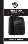
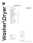
1
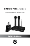
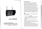
U-81 OCTAVO
SERVICE INFORMATION
Eight Discrete UHF Channels
Wireless Microphone System
(U.S.) If you are experiencing operation problem with your system, check out the support
page on the Nady website: www.nady.com for help and for contacting the Nady Service
Department. Should your wireless System require service, you must contact the Nady Service
Department at (510) 652-2411 for a Return Authorization (R/A) Number and a service quote
(if out of warranty). Make sure the R/A Number is clearly marked on the outside of the package. Cashier’s check or money is enclosed (If not prepaid with credit card), and ship the unit
prepaid to: Nady System Inc., Service Department, 6701 Shellmound Street, Emeryville, CA
94608. Include a brief description of the problem you are experiencing, for service of a unit
under warranty follow the instruction of your Warranty Card regarding Warranty Service.
(International) For service, please contact the NADY distributors in your country through the
dealer from whom you purchase this product.
The warranty card enclosed with this system contains additional valuable
warranty and service information. Keep it in a safe place for future possible
reference. Do not attempt to service this unit yourself, as it will void the warranty.
NADY SYSTEMS, INC.
6701 Shellmound Street • Emeryville, CA 94608
Tel: 510.652.2411 • Fax: 510.652.5075 • www.nady.com
OW N ER ’ S MA NUA L
NOTES
15
U-81 OCTAVO FREQUENCY PLAN
740 MHZ—764 MHz
Eight selected Frequencies in 24MHz wide Group
U8-1
740.10
U8-2
741.20
U8-3
742.70
U8-4
744.60
U8-5
747.40
U8-6
750.70
U8-7
757.60
U8-8
763.60
TABLE OF CONTENTS
TABLE OF CONTENTS ..................................................................................................3
INTRODUCTION .............................................................................................................3
USING THIS MANUAL ...................................................................................................3
SYSTEM FEATURES......................................................................................................4
U-81 OCTAVO RECEIVER OPERATION INSTRUCTIONS ...........................................5
UH-81 HANDHELD TRANSMITTER ..............................................................................7
UB-81 BODYPACK TRANSMITTER ..............................................................................8
CAUTIONS AND TROUBLESHOOTING .....................................................................11
TIPS...............................................................................................................................12
SPECIFICATIONS.........................................................................................................13
FREQUENCY PLAN .....................................................................................................14
NOTES ..........................................................................................................................15
SERVICE INFORMATION ........................................................................ BACK COVER
INTRODUCTION
Thank you for choosing the Nady U-81 OCTAVO wireless system, and congratulations
on your choice. The Nady U-81 OCTAVO wireless system is by far the best performance and price value in a professional 8 channel UHF wireless. It offers clear channel
operation on the wide-open, uncluttered UHF band for interference-free performance in
any application or locale. The Nady U-81 OCTAVO delivers eight discrete channels on
selected frequency bands from 740MHz to 764MHz. The Nady U-81 OCTAVO Wireless
system feature Nady’s proprietary companding and low noise circuit for an industry best
120dB dynamic range, and the clearest, most natural sound available in wireless today.
USING THIS MANUAL
This booklet gives instructions for the operation of the U-81 OCTAVO wireless systems:
The U-81 OCTAVO wireless microphone receiver, the UH-81 Handheld Microphone
transmitter and the UB-81 bodypack microphone/instrument transmitter.
This manual will first explain the benefits of the U-81 OCTAVO Wireless System and
then will take you step by step on how to operate your new system. Each section will
give you detailed information. Also, included in this manual are the frequency chart,
microphone-wiring guide, system specifications and servicing information.
14
3
SPECIFICATIONS
SYSTEM FEATURES
U-81 OCTAVO Wireless Receiver
• Operates on select UHF frequencies from 740MHz to 806MHz
• Eight independent single-channel UHF wireless receivers in a single housing for simultaneous operation for up to eight transmitters
• Front panel LED display indicates the RF and AF status for each channel
• Ch 1-8 individual balanced XLR MIC level outputs and Unbalanced LINE level SUM
1⁄4” jack output for 8-in-1 MIX audio output with separate volume control for each
channel
• Nady’s exclusive patented companding circuitry with 120dB dynamic range and highest
quality audio for an unsurpassed UHF performance
• Dual removable high gain antennas with TNC connector, front or back mounting
• Standard 19” 1U, all-metal rack mount housing
• Externally powered with AC/DC adapter included
• Choice of any combination of 2 transmitters: UH-81 and/or UB-81
UH-81 Handheld Microphone Transmitter
• Nady DM-50D neodymium cartridge delivers transparent vocals, maximum feedback
rejection and minimal handling noise
• ON/STDBY/OFF switch allows convenient audio muting while transmitter “ON”
• Status LED indicator flashes once for unit “ON”; lights steady for low battery alert
• 2 X AA alkaline or NiMH battery operation
• Rugged ABS and rubber-coated housing with integral antenna
UB-81 Bodypack Transmitter
• Choice of headworn or lavalier microphone operation with convenient input volume
control for proper level adjust, or instrument operation without input level control
• OFF/STDBY/ON switch allows convenient audio muting while transmitter “ON”
• Status LED indicator flashes once for unit “ON”; lights steady for low battery alert
• Single 9V alkaline or NiMH battery
• Lightweight, rugged ABS housing with integral antenna
4
OVERALL SYSTEM PERFORMANCE
RF Carrier Frequencies ............ Selected factory installed frequencies between 740MHz-806MHz
Frequency stability ......................................................................... +/-0.005% (Crystal Controlled)
Audio Deviation ..............................................................FM +/-20kHz normal, +/-50kHz maximum
Frequency Response ......................................................................................... 20Hz-20kHz, -3dB
Dynamic Range ..................................................................................................................... 120dB
Harmonic Distortion ........................................................................................... 0.5% THD, normal
Operating Range.......................................................... 250 feet normal, 500+feet max line of sight
RECEIVER
Reception ...................................................................................................Mono antenna reception
Antennas ..................................................................................10” (25.4 cm) Dual adjustable angle
Mute Threshold ....................................................................................... -95dBm (none-adjustable)
Image Rejection ..................................................................................................... -70dB, minimum
Balanced output ............................................... Audio outputs: +/-24mV variable level (600 Ohms)
Unbalanced MIX output........................................ Audio output: 360mV variable level (Open load)
Connectors........................................................... Balanced: XLR, Unbalanced: 1⁄4” TS, Antennas:
TNC connector. DC in: 2.1mm barrel type.
Indicators .............................................................................................Power On, RF and AF LEDs
Controls ...........................................................................Power ON/OFF buttons, Volume Controls
Power Requirement ................................................................................................15VDC/1000mA
Dimensions ................ 14.25” x 12” x 1.75 [W / D / H] (36.20 cm x 30.50 cm x 4.45 cm) [W / D / H]
Weight................................................................................................................... 7.20 lbs (3.37 Kg)
TRANSMITTERS
Models Available.................................................................UH-81 Handheld and UB-81 Bodypack
Input Connectors
UH-81 Handheld .......................................Integral Nady DM-50D neodymium dynamic cartridge
UB-81 Bodypack .................................................................................... 3.5mm locking mini-jack,
Controls
UH-81.......................................................................................................Power ON/STDBY/OFF
UB-81 .....ON/STDBY/OFF, Input Level Control (LT/HM), selectable inputs—GT/HM/LT switches
RF Power ........................................................... 20mW normal (50mW Maximum allowed by FCC)
Harmonics and Spurs ........................................................................................................< -50 dB
Antennas ....................................................................................... UH-81/UB-81: Internal antennas
LED Indicators
UH-81/UB-81 .............................Single LED flashes once for “ON”, lights steady for ”LOW BAT”
Battery
UH-81..........................................................................................2xAA Alkaline or NiMH batteries
UB-81 ......................................................................................Single 9V Alkaline or NiMH battery
Battery Life ......................................................................................................8-10 Hours (Alkaline)
Dimensions
UH-81.........................................................................................10.5”x 1.875” (26.7 cm x 4.8 cm)
UB-81 ................................................................... 4.25” x 2.5”x 1.0” (10.8 cm x 6.4 cm x 2.5 cm)
Weight ...............................................................................................................................................
UH-81.............................................................................................. 7.5 oz (213 g) without battery
UB-81 ................................................................................................ 3.1 oz (88 g) without battery
13
TIPS
• If the Volume Control of the receiver is set too high, it may over-driver the input of the
mixer, causing distortion. Conversely, if the output is set too low, the overall signalto-noise ratio of the system may be reduced. Adjust the output level of the receiver
such that the highest sound pressure level going into the microphone causes no input
overload in the mixer, and yet permist the mixer level control to operate in the normal
range (not too high and not too low). This provides the optimum signal-to-noise for the
entire system.
• Do not place the receiver antennas within 1 meter of another receiver or antennas.
• The receiver antennas should be kept away from any metal surface
• For the best operation, the receiver should be placed at least 1 meter above the
ground and 1 meter away from a wall or metal surfaces. All operating transmitters
should be also at least 1 meter from the U-81 OCTAVO receiver. Keep antennas away
from noise source such as motors, automobiles, neon light, signal processor, computer, as well as large metal objects.
• A single receiver cannot receive signal from two or more transmitters on the same
frequency simultaneously.
• For operation with an external antenna, low loss RF shielded cable should be used and
the length of the cable should not exceed 3m.
• Position the receiver such that it has the least possible obstructions between it and the
transmitter. Line of sight is best!
• The transmitter and the receiver should be as close as possible but never less than 1
meter.
• Before inserting the batteries, please make sure that they are inserted according to the
correct polarity.
• Use only brand new alkaline batteries. Do not use “general purpose” batteries. When
batteries are weak, replace the batteries altogether at the same time. Do not mix and
use new and old batteries together.
• Turn the transmitter off when it is not in use. Remove the batteries if it is not to be used
for a long period.
• Headset and lavalier mic users, note that the microphone element can easily be
destroyed by the buildup of salts and minerals from perspiration and saliva. It is good
practice to put a windscreen on the mic at all times to protect it.
Note: Scratchy noises can sometime occurs when some electric guitars with dirty pots
or connections are used with any wireless system. Therefore, the supplied capacitor
provides first order filtering of the RF signal from the cord into the guitar and eliminates
virtually all scratchy noises. Should your equipment still give you scratchy noises, we
suggest these steps to eliminate them:
• Make sure all guitar volume and tone pots are clean and all contacts are solid-this is
very important.
• A 47pF capacitor soldered across the pot to ground terminal of the guitar’s volume
and tone pots will provide extra filtering.
12
U-81 OCTAVO RECEIVER OPERATING INSTRUCTIONS
1. Rack-Mounting The Receiver
The U-81 OCTAVO receiver has pre-drilled holes for rackmounting. Simply attach the
Rack Mount Ears (1) on each side and fasten with supplied screws.
(Note: Do not mount the receiver in a rack directly above an amplifier or other source
of high heat. This could degrade the performance of the U-81 OCTAVO. Always ensure
adequate airflow and heat dissipation in any rack configuration.)
2. Installing Antennas
Install antennas by connecting the two antennas included with your system to the two
RF TNC connectors (2) located on the left and right backside of the U-81 OCTAVO
receiver. The optimal positions of the antennas are 45 degrees from the receiver and 90
degree from each other. For maximum range, it is always best to maintain a line of sight
(no obstruction) between the receiver antennas ant the transmitters at all time whenever
possible.
3. Powering The Receiver
Powering the receiver by plugging the provided 15VDC/1000mA adaptor into the DC INPUT jack (3) on the back of the receiver; then plug the adapter into an AC outlet. (Note:
Any 15VDC source with 1000mA capacity can also be used.) Turn volume controls of
all channels counterclockwise for minimum setting. Once the receiver is connected to
a power source, press the power switch to the ON position, Power LED indicator (4)
is ON. The TX LEDs indicator (7) and AF LEDs indicator (8) on the front panel of the
receivers will not light up at this time, but only until one or more of the eight channels is
receiving a signal from your system’s transmitters. To turn OFF, press the Power Switch
(5) to the OFF position.
4. Mute (Squelch) & RF LED Display
The U-81 OCTAVO has a preset mute (Squelch) internally for each channel for maximum range and performance. There is no need to adjust this. In normal condition,
the RF LEDs indicator (7) should be lit when a correct frequency is received from a
transmitter. However, when the RF LEDs indicator (7) is extinguished, the transmitter
is out of range for that given location, and the user should move closer to the receiver to
re-establish the radio link.
5. AF LED Display
The U-81 OCTAVO receiver is equipped with an AF LEDs indicator (8). The AF LED
indicator lights whenever an audio signal is being received from a modulated transmitter
signal. The AF LED indicator is not a peak level indicator so it can light continuously during audio signal input to the transmitter.
6. Connecting Audio Outputs
(Using the UH-81 handheld or UB-81 bodypack transmitters)
• For microphone use, the Balanced XLR out (9) or the 1⁄4” MIX out (10) can be used.
The U-81 OCTAVO audio output stage of each channel is configured for XLR balanced
microphone level, with an output loading of 600 ohms to accommodate both balanced
and unbalanced mics. Make sure the Phantom Power on your mixing board in turned
off and the volume in turn down when making the audio connections. Start the receiver
VOLUME at minimum and adjust until the level is optimal.
5
U-81 OCTAVO RECEIVER OPERATING INSTRUCTIONS
• For each channel you wish to use, insert an audio cord with a XLR female plug into its
Balanced XLR out (9) jack on the back of the receiver. Plug the other end of this cord
into your amplifier, effects or mixing board. The front panel individual receiver Volume
controls (6) can be adjusted for a suitable output level.
• The U-81 OCTAVO also has a MIX unbalanced output (10), which is a SUM line level
output of all the channels. To use it, just plug an audio cable with a 1⁄4” mono plug into
the MIX out (10) and plug the other end to your amplifier or mixing board. Turn the
volume controls on each of the channels being used clockwise to near full gain. Adjust
each volume up or down so that no audio distortion is present when the ampflier or
mixer is set at their usual levels. (Note: Turn the volume controls of any unused channel all the way off, full counter-clockwise, so that only the channels being used are in
the MIX output.)
• Your U-81 OCTAVO is now operational and ready to use. Now that you have completed
the above step, proceed to instructions for the UH-81 or UB-81 transmitters included
with your system.
Note:
• To prevent possible undesired noise during use, keep the volume controls of unused
channels (corresponding transmitter off) turned off in the amplifier or the mixer. The
audio should only be “live” if the transmitter is on.
• As when making any connection, make sure the amplifier or mixing board volume is
at the minimum level before plugging in the receiver to avoid possible sound system
damage.
• Only one transmitter can be used with one receiver. It is not possible to use two
transmitters on the same frequency and mix the output of these transmitters into one
wireless receiver.
CAUTIONS AND TROUBLESHOOTING
16. No Audio
If you are not getting audio through the U-81 OCTAVO system, slide the transmitter
POWER or MUTE (STDBY) switch to ON, carefully check all connection and system
setup. Check or replace transmitter battery. Check that the receiver is powered. The
receiver and transmitter must be set to operate on the same RF channel.
17. Audio Distorted or Unwanted Sound
Remove or turn off nearby RF sources (such as other wireless system, CB radio, CD
player, computer, digital effect, ect...) Check or replace transmitter battery.
18. Feedback
Observe care in selecting P.A. volume, transmitter location and speaker placement so
that the acoustic feedback (howling and screeching) will be avoided. Please also note
the pickup pattern characteristics of the microphone selected. Omnidirectional mics
pick up sound equally from all direction, and are prone to feedback if not used carefully.
Unidirectional mics are more resistant to feedback. However, pick up sound source
best that are directly in front of the mic. In addition, mics that are farther from the sound
source, such as lavalier, required more acoustic gain and thus are also more prone to
feed back than close-source mics such as handheld or headworn models that are used
close to the mouth.
19. RF Interference
If you encounter receiving interference (from other than an operating TV station), often
it can be checked by turning off each transmitter at a time to find the source of causing
interferences. Please note that wireless frequencies are shared with other radio services. According to FCC regulations, wireless microphone operations are unprotected from
interference from other licensed operations in the band. If any interference is received by
any Government or non-government operation, the wireless microphone must be cease
operation or change frequencies. The above statement is valid only for use in the U.S.A.
20. Signal Loss
10
9
3
Reposition the receiver and perform walk-thought test. If audio dropouts persist, locate
“dead” spots and avoid them during performance. Check receiver MUTE level setting.
Check or replace transmitter battery.
2
7
4
5
8
6
1
6
11
UB-81 BODYPACK MIC TRANSMITTER
UH-81 HANDHELD MIC TRANSMITTER
7. UH-81 Transmitter Set Up
INPUT SELECTOR
SWITCHES
Instrument
GT HM LT
GT HM LT
Headworn
Lavalier
15
GT HM LT
18
25
24
• Release the Battery cover (11) by pressing the locking tab and slide down as per arrow, exposing the Battery holder (12). Insert two fresh AA alkaline or NiMH batteries,
observing the correct polarity as marked, and slide the battery cover back on to the microphone. Make sure the cover is closed completely. Fresh alkaline batteries can last
up to 10 hours in use, but in order to ensure optimum performance, it is recommended
that you replace the battery after every 6-8 hours of use. NiMH batteries should be
replaced with fresh ones recharged fully (with separate charger, not supplied, and as
per its charging instructions) whenever low or dead battery status is indicated as per
the following.
• Turn on the UH-81 by sliding the ON/STDBY/OFF switch (13) to the STANDBY position first (transmitter on, audio muted) or the ON position (transmitter and audio both
on). The Battery indicator LED (14) will give a single quick flash, indicating usable
battery strength. In the case of dead or low batteries, the LED will either not go on
at all or will stay on continuously, indicating that the batteries should be replaced with
fresh ones. To preserve battery life, turn the transmitter off when not in use.
23
• The microphone is now ready to use. The RF Signal LED (7) on the corresponding
channel of the U-81 OCTAVO receiver should now be lit, indicating a received signal
from the same frequency transmitter. When ready to speak, slide the ON/STDBY/OFF
switch (13) to the ON position.
22
17
• Adjust the volume of the receiver as per the Connecting Audio Outputs, section 6 of the
U-81 OCTAVO receiver instructions above.
16
[Note: Observe care in selecting P.A. volume, transmitter location and speaker placement so that acoustic feedback (howling and screeching) will be avoided. Please also
note the pickup pattern characteristics of the microphone selected. Omni directional mics
pick up sound equally from all directions, and are prone to feedback if not used carefully.
Unidirectional mics, as provided with the UH-81, are more resistant to feedback, but pick
up sound sources best that are directly in front of the mic. Also, mics that are farther
from the sound source, such as lavaliers, require more acoustic gain and thus are also
more prone to feedback than close-source mics such as handheld or headworn models
that are used close to the mouth].
12
11
13
19
20
21
10
7
14
UB-81 BODYPACK MIC TRANSMITTER
8. UB-81 Transmitter Set Up
• Install by battery for the UB-81 transmitter by snap-opening the Battery door (15) and
inserting a fresh 9V alkaline or NiMH battery into the Battery compartment (16), observing the correct polarity. Close the battery door to its original position and completely cover the battery. Fresh alkaline batteries can last up to 10 hours in use, but in order
to ensure optimum performance, it is recommended that the battery be replaced after
6-8 hours of use. A NiMH battery should be replaced with another recharged fully (with
separate charger, not supplied, and as per its charging instructions) whenever low or
dead battery status is indicated as per the following.
• Selecting Audio Input Operating Mode of the UB-81. The UB-81 is equipped with two
Input selector switches (17) located under the cover on the circuit board for selecting
the type of audio input you will be supplyin g to the transmitter. Select from the choice
of three positions: INSTRUMENT (for guitar, bass, etc.), HEADWORN MIC, and LAVALIER MIC (Condenser Microphones).
• There are two switches with selectable positions GT, HM, LT together at same time.
To select inputs: (see chart on page 9)
A. Instrument — set both switches to “GT”
B. Headworn Mic — set both switches to “HM”
C. Lavalier Mic — set both switches to “LT”
(Note: Use only the input audio source as per the input selected with the internal Audio
input selector switches (17) or the audio will not be optimal–a muddy or distorted
sound may result.)
• Connection for the selected input to the UB-81 is provided with a 3.5 mm Locking jack
(18) for connecting the audio input selected. Connect either the Instrument cord (19)
or the Headworn mic (20) or Lavalier mic cord (21) as desired, according to the input
selected. To secure the connection, turn the slip ring on the plug clock wise to thread
it on the jack. To unplug, reverse the process. Slip the transmitter into a pocket or
Clip (22) it on to your clothes or instrument strap (if using the UB-81 as an instrument
transmitter).
• Turn on the UB-81 by sliding the ON/STDBY/OFF switch (23) to the STANDBY position (transmitter on, audio muted) or the ON position (transmitter and audio both on).
The Battery indicator LED (24) will give a single quick flash, indicating usable battery
strength. In the case of a dead or low battery, the LED either will not go on at all or will
stay on continuously, indicating that the battery should be replaced with a fresh one. To
conserve battery life, turn unit off when not in use.
• The U-81 transmitter is now ready to use. The RF Signal LED (7) on the corresponding channel of the U-81 OCTAVO receiver should now be lit, indicating a received
signal from the same frequency transmitter.
• Adjust the volume of the receiver as per the Connecting Audio Outputs, section 6 of
the U-81 OCTAVO receiver instructions above. [Note: Observe care in selecting P.A.
volume, transmitter location and speaker placement so that acoustic feedback (howling
8
UB-81 BODYPACK MIC TRANSMITTER
and screeching) will be avoided. Please also note the pickup pattern characteristics of
the microphone selected. Omni directional mics pick up sound equally from all directions, and are prone to feedback if not used carefully. Unidirectional mics are more
resistant to feedback, but pick up sound sources best that are directly in front of the
mic. Also, mics that are farther from the sound source, such as lavaliers, require more
acoustic gain and thus are also more prone to feedback than close-source mics such
as handheld or headworn models that are used close to the mouth].
9. Microphone Use (with either a lavalier or headworn mic)
• Secure the connection from the Lavalier (21) or Headworn mic cord (20) by turning
the slip ring on the plug into the transmitter clockwise to thread it on to the jack. To unplug, reverse the process. To use the lavalier mic, attach it at chest level. Do not place
it too close to the mouth–a distance of about six inches usually works best. To use the
headworn mic, place it on the head and adjust the boom so that the mic is about one
inch to the side of the front of the mouth. When ready to speak, slide the ON/STDBY/
OFF switch (23) to either the “STDBY or ON” position.
• For optimum performance, an Input level control (25) is provided. Adjust the gain by
turning the control with a small screwdriver. For lavalier mic use, it is recommended
that the level be set at about 1/2 maximum. For headworn mic use, it may be advisable
to turn the gain down somewhat, depending on the volume levels expected. In either
application, experiment and set for maximum possible gain without audible distortion
on the high level peaks.
(Note: Turning down the gain too much can compromise the signal-to-noise and it is not
recommended.)
10. Instrument Use (Optional)
Secure the connection from the GT cable (19) by turning the slip ring on the plug into
the transmitter clockwise to thread it on the jack. To unplug, reverse the process. Plug
the 1/4” phone plug into the instrument. When ready to play, slide the audio ON/STDBY/
OFF switch (23) to either the “STDBY or ON” position Adjust the volume of the receiver
as per the Connecting Audio Outputs, section 6 of the U-81 OCTAVO receiver instructions above.
[Note: The Input level control (25) is deactivated and not used when the UB-81 is in
Instrument (GT) mode. Levels should be adjusted with the volume control of your instrument.]
[Note: Scratchy noises can sometimes occur when some electric guitars with dirty pots
or connections are used with any wireless system. Therefore, the supplied Instrument
cord (19) has a factory-installed capacitor inside the 1/4” plug. This capacitor provides
first order filtering of the RF signal from the cord into the guitar and eliminates virtually all
scratchy noises. Should your equipment still give you scratchy noises, we suggest these
steps to eliminate them:
• Make sure all guitar volume and tone pots are clean and all contacts are solid–this is
very important.
• A 47pf capacitor soldered across the hot to ground terminals of the guitar’s volume
and tone pots will provide extra filtering.]
9