1
OWNER’S MANUAL
PRM-400
6 Channel Powered Mixer
with Internal DSP Effects
PRM-400
6-CHANNEL POWERED MIXER WITH INTERNAL DSP EFFECTS
Congratulations on your choice of powered mixers — you
have purchased one of the finest compact mixing consoles
on the market today. This unit was developed using the
expertise of professional sound engineers and working musicians. You will find that your new NADY AUDIO PRM-400
has superior performance and greater flexibility than any
other powered mixer in its price range. Please read this
manual carefully to get the most out of your new unit.
Date of Purchase
Dealer’s Name
City
State
Zip
Thanks for selecting NADY AUDIO as your choice in mixing
consoles.
Model #
Serial #
CONTENTS
WARNING ..........................................................................................................................................................3
FEATURES ...................................................................................................................................................... 4
INSTALLATION..................................................................................................................................................
1. Inspection ......................................................................................................................................................
2. Rack Mounting ..............................................................................................................................................
3. Setup and Operation ......................................................................................................................................
5
5
5
5
CONTROLS AND CONNECTIONS .................................................................................................................. 6
1. Channel Input Section ....................................................................................................................................6
2. Master Section ................................................................................................................................................8
a. Aux Sends/Returns Function and Operation .......................................................................................... 8
b. Master Mix Function and Operation ........................................................................................................8
c. Digital Echo Effects Function Operation ................................................................................................10
d. Monitor Function and Operation ............................................................................................................10
e. Power Connection, Indicators, and Switches ........................................................................................11
4. Connections ................................................................................................................................................12
SPECIFICATIONS............................................................................................................................................ 13
BLOCK DIAGRAM ..........................................................................................................................................14
2
WA R N I N G
An equilateral triangle enclosing a lightening flash/arrowhead symbol is
intended to alert the user to the presence of uninsulated “dangerous
voltage” within the product’s enclosure which may be of sufficient
magnitude to constitute a risk of electric shock.
ATTENTION: RISQUE DE CHOC ELECTRIQUE NE PAS OUVRIR
An equilateral triangle enclosing an exclamation point is intended to alert
the user to the presence of important operating and service instructions in
the literature enclosed with this unit.
IMPORTANT SAFETY INSTRUCTIONS
When using this electronic device, basic precautions should always be taken, including the following:
1. Read all instructions before using the product.
2. Do not use this product near water (e.g., near a bathtub, washbowl, kitchen sink, in a wet basement, or near a
swimming pool, etc.).
3. This product should be used only with a cart or stand that will keep it level and stable and prevent wobbling.
4. This product, in combination with headphones or speakers, may be capable of producing sound levels that
could cause permanent hearing loss. Do not operate for a long period of time at a high volume level or at a
level that is uncomfortable. If you experience any hearing loss or ringing in the ears, you should consult an
audiologist.
5. The product should be positioned so that proper ventilation is maintained.
6. The product should be located away from heat sources such as radiators, heat vents, or other devices
(including amplifiers) that produce heat.
7. The product should be connected to a power supply only of the type described in the operating instructions or
as marked on the product. Replace the fuse only with one of the specified type, size, and correct rating.
8. The power supply cord should: (1) be undamaged, (2) never share an outlet or extension cord with other
devices so that the outlet’s or extension cord’s power rating is exceeded, and (3) never be left plugged into
the outlet when not being used for a long period of time.
9. Care should be taken so that objects do not fall into, and liquids are not spilled through, the enclosure’s
openings.
10. The product should be serviced by qualified service personnel if:
A.
The power supply cord or the plug has been damaged.
B.
Objects have fallen into, or liquid has been spilled onto the product.
C. The product has been exposed to rain.
D. The product does not appear to operate normally or exhibits a marked change in performance.
E.
The product has been dropped, or the enclosure damaged.
11. Do not attempt to service the product beyond what is described in the user maintenance instructions. All
other servicing should be referred to qualified service personnel.
3
F E AT U R E S
The PRM-400 is compact desk console or rackmountable 200W/channel stereo powered mixer with 16 built-in selectable preset DSP echo and reverb effects and a comprehensive mixer section with extensive routing capability. The
PRM-400 is a versatile audio tool that combines exceptional flexibility and performance, and is ideal for many small
venue/live sound reinforcement applications.
• Superior audio performance with low noise and powerful,
full-spectrum transparent audio and natural sounding selectable echo/reverb effects
• High quality sealed pots with center detents (EQ, EFF,
PAN)
• 6 mono balanced XLR mic and balanced 1/4” line inputs,
trim controls and switchable 20dB pads, 3-band EQ’s, Peak
overload LEDs, Aux, Effects and Pan controls
• Built-in DSP (Digital Sound Processor) for ECHO
(REVERB) with 16 selectable preset level and echo intervals and separate Repeat control, Effects Return and both
individual channel and master mix Effects Send controls,
master Effects fader, separate effects PFL monitoring, and
numeric LED display
• Tape In and Record Out RCA jacks with Tape level control
• Aux/Monitor switch allows the PRM-400 to be used as
either a stereo main (FOH) or a mono main and monitors
powered mixer
• Stereo power amplifier delivers 200W/side @ 4 Ohms. Fancooled, bipolar amplifier design for longest life and maximum reliability.
• Headphone output with separate volume adjust
• Dual 7-band master graphic EQ (with bypass switch) can
be used in stereo or mono for main and monitor EQ
• Switchable global 48V phantom power
• Aux Send and Aux Return with Aux Send and Aux Return
controls
• Erasable area above all faders for notations
• PFL control for each channel allows headphone monitoring
independent of channel volume
• Dual 10-segment LED meter for L/R main and PFL
• Internal AC supply with 115/230V select switch
• Six 1/4” TRS inserts allow independent connection of
effects devices for each mono channel
• Road-tough all steel construction. Rack ears supplied.
• Dimensions & Weight: 16” x 17” x 6” (406 x 432 x 152
mm), 27.8 lbs (12.6 Kg)
• Stereo Master inserts with Pre EQ and Post EQ 1/4” TRS
jacks
• 60 mm faders on all channels and master L/R and Effect
bus mix for precise level control
4
I N S TA L L AT I O N
To ensure years of enjoyment from your NADY AUDIO PRM-400 powered mixer console, please read this manual thoroughly
before using the unit.
1. INSPECTION
Your NADY AUDIO PRM-400 was carefully packed at the factory in packaging designed to protect the units in shipment.
Before installing and using your unit, carefully examine the packaging and all contents for any signs of physical damage that
may have occurred in transit.
[Please note: Nady Systems is not responsible for shipping damage. If your unit is damaged, do not return to Nady, but
notify your dealer and the shipping company (if shipped to you) immediately to make a claim. Such claims must be made by
the consignee in a timely manner.]
2. RACK MOUNTING
Enclosed in the shipping box you will find a rackmount kit. If you want to make your PRM-400 a rack mixer, remove the
screws from the side panels and use them to attach the rack ears.
(Note: The rack ears are supplied as “left” and “right” and must be attached as such.)
3. SETUP AND OPERATION
Parts of the unit can become very warm during use. This is normal during operation. Care should be taken to ensure that
there is enough space around the unit for cooling (at least 12” or 30cm). Do not place the PRM-400 on high temperature
devices such as power amplifiers, etc., or the unit may overheat in operation. Also, do not place the unit on speakers as this
may cause them to move and/or fall due to speaker vibrations.
Although the unit’s chassis is shielded against radio frequency (RF) and electromagnetic interference (EMI), extremely high
fields of RF and EMI should be avoided.
The PRM-400 has an internal power supply and is designed to operate from an external AC source. Power requirements
for electrical equipment differ from area to area. Be sure to confirm that the voltage selected by the voltage selector switch
on the back panel is proper for your area (120VAC/60 Hz or 230VAC/50Hz) per the information below:
Europe (except UK): 230V, 50Hz
UK and Australia: 240V, 50Hz
USA and Canada: 120V, 60 Hz
For other areas, please check with local authorities.
When ready to operate, plug the AC cord into the power source. Make sure that the unit is turned off before connecting to
the AC power source to avoid possible loud transients which can damage your speakers or your ears, especially when monitoring with headphones. Set the noted controls to the positions indicated below to further minimize the chance of undesired
noise when first powering up your PRM-400 :
LEVEL FADERS (11,27A,27B,28) ................................................................................................................SET TO MINIMUM
HI, MID & LOW EQ’S (6) AND PAN CONTROLS (9)..................................TURNED TO THE CENTER DETENT POSITION
AUX , EFF CONTROLS & PHONES LEVEL CONTROLS (7,8,36) ..........TURNED COMPLETELY COUNTERCLOCKWISE
ALL OTHER CONTROLS SHOULD ALSO BE TURNED COMPLETELY COUNTERCLOCKWISE.
Power up the unit as noted in Power Connections, Indicators, and Switches (Section 3e in CONTROLS AND
CONNECTIONS).
5
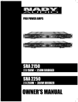
CONTROLS AND CONNECTIONS
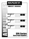
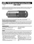
1. CHANNEL INPUT SECTION
which are usually added to the dry signal, dynamic processing is normally applied across an entire signal. Here an Aux
Send would be inappropriate. Instead, the signal is intercepted somewhere along the channel, fed through the dynamics
processor and/or EQ, then returned to the console at the
same point where it left. The insert point is normalized, i.e.,
the signal is only interrupted when a plug is plugged into it.
The insert jack is located post EQ in the channel and is configured as: Tip = send, Ring = return, Sleeve = ground. The
Insert can also be used as a channel direct output by sending
the signal from the ring. To use the Insert as a direct output,
insert a 1/4” phone plug halfway into the Insert jack so the tip
of the plug connects with the ring of the insert jack. The jack
will click into place when the connection to the ring is made.
(1) MIC INPUT
The Mic input is an electronically balanced XLR
type designed to accept
from any bal(1) signals
anced low impedance
(Low Z) microphone. To
accommodate condenser
microphones, this input is
also equipped with
(2) +48VDC phantom power
globally switchable to all
XLR input jacks with the
Phantom Power switch
(23) on the master
(3)
Section of the front panel.
Dynamic or ribbon-type
microphones do not
require phantom powering. It will be necessary to
adjust the channel gain with the input Trim control (4) and/or
Pad switch (5) to achieve a nominal operating level. The
XLR jack is configured for: Pin1 = ground, Pin2 = positive (+),
Pin3 = negative (-).
(4) TRIM
The trim control adjusts the input sensitivity (channel gain) of
the Mic and Line inputs on the input channels. This control
can be adjusted to accommodate input signals from a wide
variety of sources, from the high outputs from keyboards or
drum machines to the small signal outputs of microphones.
The trim control adjusts the input sensitivity from -20dB to
-60dB with the -20dB Pad
switch (5) in the OUT
position, and -40dB to 0dB
(4A)
with the pad in the IN (button depressed) position.
The best balance of S/N
(4)
and dynamic range will be
achieved if you adjust the
TRIM control on each
channel separately so that
the Peak Indicator LED
(5)
(4A) for that channel lights
occasionally.
[Note: The Mic inputs are more sensitive than the Line inputs.
Also, do not connect mics with the phantom power switched
on, as indicated by the Phantom Power On LED (24) in the
Master Section of the front panel. Never use unbalanced mic
cables with the Phantom Power switched on. Never short the
+48VDC to ground, as that can cause serious damage to
your mixer. Also, turn down the Stereo Master faders (27A,
27B) to prevent possible sharp transient noise from damaging
the speakers when turning the phantom power on or off.]
(2) LINE INPUT
The Line input is designed to accept balanced or unbalanced
line-level signals such as those from keyboards, drum
machines, or samplers. There is enough gain available on the
line input to accept even lower level signals, such as those
from an unbalanced microphone or guitar output. Use the
Trim control (4) and/or Pad switch (5) to adjust for the
desired level. If a balanced signal is to be connected to the
line input, then a 1/4” TRS (stereo) phone plug should be
wired for: Tip = positive (+), Ring = negative (-), Sleeve =
ground.
(4A) PEAK LED INDICATOR
The Peak LED illuminates
when a channel is going
into overload. It detects
the peak level after the EQ
and will light at approximately 5dB before clipping
to warn that the signal is
approaching overload. You
do not want the Peak LED
to light except very intermittently during a take or a
mix. If it does light persistently, reduce input gain
with the TRIM control (4)
or PAD (5).
(Note: Only the Mic or the Line input of a given channel can
be connected at one time. Never connect both simultaneously
to the same channel.)
(3) INSERT
All 6 channels are equipped with insert jacks to connect
external signal processors such as compressors, noise reduction systems, or effects devices to the individual input channels. Insert points are useful for adding dynamic processing
or equalization to a channel or the mix. Unlike reverbs, etc.,
6
(6)
CONTROLS AND CONNECTIONS
(7)
(5) PAD
This control attenuates the
input signal -20dB when
set to the IN (button
depressed) position.
The key to successful equalization is to avoid excess. Too
much equalization on the input channels will result in a mix
that is smeared together with nothing specifically defined.
During rehearsals, experiment with the equalizer controls on
various instruments, vocals and combinations of these mixed
together to become familiar with various equalizer settings.
(6) EQUALIZER CONTROLS
(8) All input channels are fitted with a three-band EQ.
All three bands have up to
15 dB of cut and boost,
with a center detent for
“off”. The frequency
(9) response is flat when all
three EQ knobs are in the
center detent position. The
upper and lower shelving
have their fre(10) controls
quencies fixed at 12 kHz
and 80 Hz respectively.
The midrange control has
a peaking response at
2.5KHz (Q fixed at 1
octave). The channel EQ
is a valuable feature of the
mixer as it allows the user
to control the tonal characteristics of each instrument
separately. For example,
boosting the LOW can fatten the sound and add
punch to the bass or
drums; the MID control
(11) can be used to define the
midrange or bring out the
vocals; and adjusting the
HIGH control can provide
a crisp sounding high end.
Another very important,
yet often overlooked technique is to use the EQ to
subtract from the mix.
Cutting the HIGH control
can reduce unwanted hiss
during multi-track recording, while attenuating the
MID or LOW can eliminate
feedback in a live performance or clear up a muddy sounding mix. Cutting away the top
and bottom, then pushing up the Gain is equivalent to mid
range boost!
(7) AUX (POST) SEND CONTROLS
The Aux send controls are mono and post-EQ and pre-fader
and the signal level sent to the AUX bus will be unaffected by
the channel fader setting. This configuration is ideal for
almost all monitoring purposes, for example, for a separate
stage monitor mix in live performances or a studio room monitor in recording applications, such as for a headphone cue
system.
(8) EFF (EFFECTS) CONTROLS
The EFF control are mono, post-EQ and pre-fader and the
signal level sent to the EFFECTS bus will be unaffected by
the channel fader setting. These controls adjust the level sent
by each channel to the internal DSP (Digital Sound
Processor). (See also Digtal Echo Effects Function and
Operation)
(9) PAN
The Channel Pan positions the output of the channel in the
stereo field of the main mix. Its constant-power design
ensures there are no level discrepancies whether a signal is
hard-panned, center-stage, or somewhere in between.
(10) PFL SELECT SWITCH
The PFL (pre-fader listen) switch enables monitoring the signal of any channel(s) selected (button depressed) at nominal
levels through the headphone output. The signal is post EQ
and independent of channel fader position. Selecting the PFL
never interrupts the main stereo out or the AUX sends.
(11) CHANNEL FADER
The channel faders determine the output signal level to the
Master Mix Left, Right busses. They offer a smooth logarithmic taper for optimum control of the signal, more often associated with much more expensive consoles.
[Note: Always reset a channel’s input Gain (or external
device’s output level) after altering the amount of mixer equalization cut or boost applied.]
7
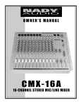
CONTROLS AND CONNECTIONS
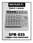
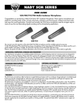
2. MASTER SECTION
(13)
(16)
(17)
(12)
(14)
(18)
(15)
(22) 7 BAND MASTER MIX GRAPHIC EQUALIZER
(25) EQ BYPASS SWITCH
(26) AUX/MON SELECT SWITCH
(14) STEREO MASTER INSERTS-PRE EQ
(15) STEREO MASTER INSERTS-POST EQ
The final Master Mix is output directly to the Main Speaker
outputs (42). These L/R outputs provide 200W at 4 ohms for
powering P.A. speakers rated for this power or more. Channel
A and B parallel outputs allow multiple speaker setups. You
can also access this Master Mix by utilizing the send function
of the Stereo Master Inserts (see below). The Record Out
(17) jacks output the Master Mix post-Stereo Master faders
(27A, 27B) and are pre-Master EQ (22) and pre-Stereo
Master Inserts (14,15). These outputs are RCA jacks, and
designed primarily for inputs to tape recorders, etc.
a. AUX Send/Return Function and Operation
(13) AUX RETURN
(31) AUX RETURN CONTROL
The Aux Return jack enables a convenient input to the left
and right Master Mix busses. If you connect a signal to the
Return jack, the Aux Return will operate in mono and the signal will be routed to the Aux Return Control (31) and then
mixed into the left and right Master Mix bus. The Aux Return
is multi-functional. It may be used for returning the outputs of
effect units such as Tape Returns from a multi-track recorder,
or as extra instrument inputs such as from a MIDI keyboard.
(12) AUX SEND
(30) MASTER AUX SEND CONTROL
The Aux Send jack is the unbalanced output for the signals
from the Aux bus. It is pre-fader. This signal can be sent to
the input of an effects processor, multi-track recorder, or used
for any other line-level auxiliary purpose, such as monitor
feeds. The Aux Send level is adjusted by the channel Aux
Send controls (7) and the Master Aux Send control (30).
When the Aux/Mon switch (26) is in the depressed IN position, the Aux send also functions as the mono output of the
Master Right Channel bus. (See also Master Mix Function
and Operation below)
The output level routed to the Speaker outputs and REC outputs is determined ultimately by the setting of the Stereo
Master faders (27A, 27B). The Master Mix (signal on the
L/R main busses) is the sum of the signals routed from all the
channels and also the inputs from the EFFECTS and AUX
busses and the TAPE Input (16). The level input from the
Tape In (16) is adjusted with the Tape In Level control (29).
The level of signal routed to the Stereo Master faders
(27A,27B) from DAT, tape decks, CD players, etc., input to
the Tape Input (16) is determined by the setting of the output
volume control of the audio device being connected and the
Tape In Level Control (29), so care must be taken in adjusting these levels so as to achieve proper balance in the final
mix and to prevent overload distortion. The 10-stage LED
Output Meter (19) can be used to maintain proper levels in
the master mix.
b. Master Mix Function and Operation
(42) MAIN SPEAKER OUTPUTS
(16) TAPE INPUTS
(29) TAPE IN LEVEL CONTROL
(17) REC OUTPUTS
(27A,27B) STEREO MASTER MIX FADERS
(19) LED OUTPUT METER DISPLAY
8
CONTROLS AND CONNECTIONS
The PRM-400 is equipped with a 7band Stereo Graphic Equalizer
(22), allowing final tonal adjustments
on the Master Mix. This master EQ
is post-Stereo Master faders
(27A,27B) so you must exercise
care in the proper use of these EQs
for best overall sound [see also
INPUT SECTION, (6) EQ above].
The EQ Bypass switch (25) can be
used to add or eliminate the Stereo
EQ from the Master Mix (button
depressed=EQ bypassed).
Further processing of the Master
Mix can be done by utilizing the
stereo Master Inserts (14,15). The
PRE EQ insert (14) inserts a signal
from an outboard processor, as
desired, between the Stereo Master
faders (27A,27B) and the Stereo
Graphic Equalizer (22), while the
POST EQ insert(15) inserts it POST
EQ and before the PRM-400 internal
power amp. The insert points are
normalized, i.e., the signal is only
interrupted when a jack is plugged
into it. The insert jacks are configured as: Tip = send, Ring = return,
Sleeve = ground.
The Inserts can also be used as
Master Mix pre or post-EQ direct
outputs by sending the signal from
the ring. To use an insert as a direct
output, insert a 1/4” phone plug
halfway into the insert jack so the tip
of the plug connects with the ring of
the insert jack. The jack will click
into place when the connection to
the ring is made. Such outputs can
thus serve as feeds for external
amplifiers or recording devices, for
example.
The Aux/Mon Select switch (26)
can be used to switch between normal stereo L/R to dual mono operation, such as for powering separate
mains and monitor speakers with
the PRM-400. The UP position is for
stereo operation as described
above, and the DOWN (depressed)
position enables dual mono operation as follows: The Left speaker
output is a mono mix of both the
Left and Right signals as controlled
(20)
(19)
(21)
(19A)
(24)
(23)
(22)
(25)
(26)
(27A)
(28)
(27B)
9
CONTROLS AND CONNECTIONS
by the Channel faders, and the Right speaker output is the
signal controlled by the Channel AUX controls (7).
Therefore the Main speakers, for example, can be controlled
by the individual Channel faders (11) and the Left Master
fader (27A), and the Monitor speakers by the Channel AUX
controls (7) and the Right Master fader (27B). In this
mode, any Master EQ (22) or Effects (8,28,32) selected on
the EFECTS bus will be output on both the Left and Right
Speaker outputs. The Left and Right Master inserts (14,15)
operate individually on either channel as in normal stereo
operation.
(29)
(30)
c. Digital Echo Effects Function and Operation
(20) EFFECTS DISPLAY
(21) ECHO EFFECT SELECT BUTTONS
(32) EFFECT SEND
(33) EFFECT (ECHO) REPEAT
(34) EFFECT PAN
(35) EFFECT PFL
(28) EFFECT FADER
The built-in DSP (Digital Sound Processor) offers 16 different
preset level and echo intervals selectable by the Echo Effect
Select UP/DOWN buttons (21). Press either button to scroll
in either direction through the 16 presets. The numeric
Effects Display (20) will indicate which of the 16 effect presets has been selected. The DSP processes the signal on the
EFFECTS bus, which is the sum of the 6 individual channel
inputs controlled by the EFF control (8). The EFFECT SEND
control (32) adjusts the level of the signal on the EFFECTS
bus fed to the DSP. The EFFECT (ECHO) REPEAT control
(33) adjusts the number of repeats of the echo effect selected
with the UP/DOWN buttons (21) and the EFFECTS fader
(28) controls the signal level sent to the Master Mix busses.
The output of the DSP is sent proportionately to the Left and
Right Master Mix busses as adjusted by the EFFECT PAN
control (34). The EFFECT PFL button (35) can be
depressed to monitor the pre-EFFECTS fader (28) DSP output through the Monitor Headphones jack (37).
(31)
(32)
(33)
(34)
d. Monitor Function and Operation
(37) HEADPHONES OUTPUT
(36) PHONES LEVEL CONTROL
(18) MONO MONITOR OUTPUT
(35)
The PRM-400 allows you to monitor the Stereo Master Mix or
any signals selected by the channel PFL (10) or EFFECTS
PFL (35). The signal level is adjusted with the Phones Level
control (36) and routed to the Headphones (37) output. The
Phones Output (37) will feed headphones and is a 1/4” TRS
jack, wired: tip = left signal, ring = right signal, sleeve =
ground. (Note: Use only headphones with an impedance
>50 Ω or you may experience some distortion.)
If desired, this output can also be connected instead to an
amplifier and speakers for control room or stage monitoring.
The MONO Monitor Out Jack (18) is another useful output
which can be used to feed a signal to a monitor amp or other
mixer. The signal on this output is taken from the AUX bus
(36)
(37)
10
CONTROLS AND CONNECTIONS
(38)
(40)
(39)
(42)
(41)
BACK PANEL
The PRM-400 is fused for your (and its own) protection. If a
fuse blows, disconnect the AC cord, and replace the fuse
with a 6.0A (5x20mm, 250V) type, available at electronics
stores or through your dealer. If the fuse blows continuously
upon replacement, unplug the unit and refer to qualified personnel for servicing before further use.
and is pre the master AUX send control (30). When the
AUX/MON switch (26) button is depressed, this output
serves as the monitor output for the Right bus (see also
Master Mix Function and Operation).
e. Power Connection, Indicators, and Switches
(39) AC POWER CORD
(38) MAIN POWER SWITCH
(40) 115/230VAC POWER SELECTOR SWITCH
(19A) POWER ON LED INDICATORS
(41) FUSE HOLDER
(23) PHANTOM POWER SWITCH
(24) PHANTOM POWER ON LED INDICATOR
When using condenser mics, +48VDC can be switched globally on or off to the XLR mic inputs for all six channels (also
see INPUT SECTION, MIC INPUTS). When this switch is in
the ''ON'' position (button depressed), the Phantom Power
On LED Indicator (24) will light, and +48VDC will be provided between pins 2 and 3 of all the Mic input XLR connectors. If you don’t need phantom power, be sure to turn this
switch to the ''OFF'' position.
Check the power source for the voltage (115VAC or 230VAC)
in your area and switch the Power Selector switch (40) to
select the proper voltage. Once you have connected the AC
power cord (39) to the AC power source, switch on your
mixer with the Power On switch (38). The Power ON LED
Indicators (19A) will light up. Allow 1 minute after powering
up for the system to reach equilibrium before setting input
gains and other levels. You can leave the PRM-400 on all the
time. It is conservatively designed, so heat build-up isn’t a
problem even in 24-hour-a-day operation. There’s nothing that
will burn out or get used up. Alternatively, you can just plug
every unit in your total system into a Nady Power
Conditioner PCL-800/810/815 or a good quality power strip,
for one-button turn-on.
[Note: It is safe to connect balanced dynamic mics or line
level devices even if this switch is on, but connecting unbalanced devices or devices whose transformers are centergrounded will cause hum or malfunctions. Shorting the
+48VDC can also damage your mixer. Also, turn down the
Stereo Master faders (27A, 27B) to prevent possible sharp
transient noise from damaging the speakers when turning
the phantom power on or off.]
11
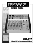
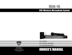
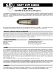
CONNECTIONS
This NADY AUDIO powered mixer uses 4 different types of audio connectors for the various input/output connections: (1) XLR
balanced; (2) 1/4” TRS phone jacks for balanced, unbalanced, stereo, or in/out inserts; (3) 1/4” TS unbalanced;
(4) RCA pin unbalanced
Figures
1. Balanced XLR input/output connections
2. Stereo headphone connection with 1/4" TRS
plug
GROUP & MIX OUTPUTS
MICROPHONE INPUTS
3. 1/4" mono (TRS) plug used as unbalanced
input/output
2
1
2
1
Ground (Screen)
3
3
4. 1/4" stereo (TRS) plug used as balanced
input/output
Cold
(Out of Phase Signal)
5. 1/4" TRS plug used as Insert Send/Return
Hot
(In Phase Signal)
6. RCA pin plug for unbalanced input/ouput
HEADPHONES
Socket (female)
UNBALANCED USE OF
MONO 1/4” PLUGS
Tip =
Left signal
Tip =
Signal
Plug (male)
BALANCED USE OF
STEREO 1/4” PLUGS
Tip =
hot (+ve)
Ring =
Right signal
Ring =
cold (-ve)
Sleeve =
Ground/Shield
Sleeve =
Ground/Shield
Tip
Ring
Sleeve =
Ground/Shield
Tip
Tip
Ring
Sleeve
Sleeve
Strain relief
clamp
Strain relief
clamp
2.
Sleeve
3.
1/4” STEREO PLUG USED AS INSERT SEND/RETURN
TIP
Send to External
Device
SLEEVE
Ground (Screen)
Strain relief
clamp
4.
RCA PIN PLUG
Strain relief clamp
Sleeve =
Ground
(Shield)
RING
Return from External Device
Ring
Sleeve
Tip
12
5.
Pin =
Signal
6.
1.
S P E C I F I C AT I O N S
1. POWER OUTPUTS (R.M.S)
9. HEADPHONE OUTPUTS
200 Watts (35W + 35W) /4Ω x 2
0.1% (T.H.D) @ 1KHz
40mW x 2
10. PROTECTION
2. TOTAL HARMONIC DISTORTION
Main Amp ≤ 0.05% @1KHz
Mic Ch ~ Main Amp ≤ 0.1% @1KHz
TURN ON MUTING .................................................... ~ 1 SEC
TURN OFF MUTING ..................................................INSTANT
11. VU METERS
3. FREQUENCY RESPONSE
10-segment LED x 2
± 3dB, 20Hz ~ 20KHz @ 1W/4Ω (Speaker Output)
± 3dB, 20Hz ~ 20KHz @ +4dB/10Ω (Mixer Stereo Output)
12. PHANTOM POWER
+48VDC, globally selected
4. INPUT LEVEL SENSITIVITY
MIC CH ..........................................................................-60dBv
LINE CH ........................................................................-40dBv
TAPE IN ........................................................................ -40dBv
AUX RETURN .............................................................. -20dBv
EFF SEND .................................................................. -20dBv
EFF RETURN .............................................................. -20dBv
13. POWER REQUIREMENTS
Voltage Selectable ......................115VAC/60Hz, 230VAC/50Hz
14. POWER CONSUMPTION
600W
5. HUM & NOISE
≤ -80dB ("A" FILTER)
15. FUSE
115VAC Operation ......................................6A, 5x20mm, 250V
230VAC Operation ......................................3A, 5x20mm, 250V
6. REMAINING NOISE
≤ -85dB ("A" FILTER)
16. DIMENSIONS (W x H X D)
16” x 17” x 6” (406 x 432 x 152 mm)
7. INPUT CHANNEL EQUALIZATION
MIC, LINE, & PHONO INPUTS:
EQ
HIGH (Shelving) ......................................10KHz / ±15dB
MID (Bell) ................................................2.5KHz / ±15dB
LOW (Shelving) ..........................................60Hz / ±15dB
17. WEIGHT
27.8 lbs (12.6 Kg)
8. MASTER MIX EQUALIZATION
7 band (63Hz, 150Hz, 400Hz, 1KHz, 2.5KHz, 6.4KHz,
15KHz) +/-12dB
The specifications above are correct at the time of printing of this manual. For improvement purposes, all specifications for this unit,
including design and appearance, are subject to change without prior notice.
13
BLOCK DIAGRAM
14
SERVICE FOR YOUR NADY AUDIO PRODUCT
(U.S.) Should your NADY AUDIO product require service, please contact the Nady Service Department via telephone at (510) 652-2411, or e-mail at [email protected].
(International) For service, please contact the NADY AUDIO distributor in your country through the dealer from
whom you purchased this product.
DO NOT ATTEMPT TO SERVICE THIS UNIT
YOURSELF AS IT CAN BE DANGEROUS
AND WILL ALSO VOID THE WARRANTY.
NADY SYSTEMS, INC. • 6701 SHELLMOUND STREET, EMERYVILLE, CA 94608
Tel: 510.652.2411 • Fax: 510.652.5075 • www.nadywireless.com