1
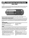
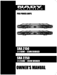
INPUT/OUTPUT LEVEL(dB)
-30
-24
-18
-12
-6
0
PEQ-5B
5 Band
Parametric
Equalizer
-3
0
+10
+15
dB
INPUT
OUT
IN
AUDIO
+9
400
Hz
LOW CUT
BAND 1
+18
0
-5
2.5
30
-15
+15
OUT
KHz
dB
IN
HIGH CUT
LEVEL
AUDIO
0
110
150 -5
1.2 80
-10
1.6
22
0.03
2
OCTAVE
BANDWIDTH
-5
20
400
Hz
FREQUENCY
+10
-10
+15
dB
IN
AUDIO
-10
1.6
0.03
2
OCTAVE
BANDWIDTH
-5
60
1k
Hz
FREQUENCY
BAND 4
-10
-15
+15
dB
LEVEL
OUT
IN
AUDIO
900 -5 -5
1.2 400
-10
1.6
22
0.03
2
OCTAVE
BANDWIDTH
Hz
-15
+15
OUT
dB
IN
LEVEL
AUDIO
2.7 -5 -5
110 1.5
-10
1.6
0.03
2
OCTAVE
BANDWIDTH
2.5
30
kHz
FREQUENCY
4
0.8
1.2 7
0.4
+5
4.6
0.7
22
1kHZ-20kHz
0
1.8
0.8
0.1
+10
-10
2.5k
150
FREQUENCY
BAND 5
500HZ-8kHz
0.4
+5
1.4k
22
200
0.1
+10
0
600
0.8
0.4
+5
550
80
OUT
LEVEL
350 -5
1.2 160
150HZ-2.5kHz
0
250
0.8
0.1
-15
BAND 3
60HZ-1kHz
0.4
+5
250
40
0.1
+10
BAND 2
20kHZ-400kHz
0.8
0.4
+5
22
-10 -10
3.5
22
10
+12
15
200
25
-10
+6
10
110 7
50
+5
-15
+3
75
-5
-10
-15
OUT
+15
IN
AUDIO
PEQ-5B
5-BAND PARAMETRIC EQUALIZER
OWNER’S MANUAL
10
-10
1.6
22
0.03
dB
LEVEL
POWER
6.5
1.5
0.1
+10
2
OCTAVE
BANDWIDTH
2.5
20
KHz
FREQUENCY
PEQ-5B
5-BAND PARAMETRIC EQUALIZER
Congratulations!
Date of Purchase__________________________
You have purchased one of the finest professional parametric equalizers on the market today. This unit was
developed using the expertise of professional sound
engineers and working musicians. You will find your new
NADY AUDIO PEQ-5B has superior performance and
greater flexibility than any other parametric equalizer in
its price range. Please read this manual carefully to get
the most out of your new unit. Thanks for selecting NADY
AUDIO as your choice in parametric equalizers.
Dealer’s Name____________________________
City_____________________________________
State___________ Zip______________________
Model#__________________________________
Serial #__________________________________
Contents
CONTENTS .......................................................................................................................................... 2
WARNING.............................................................................................................................................. 3
FEATURES .......................................................................................................................................... 4
INSTALLATION ...................................................................................................................................... 5
1. Inspection ........................................................................................................................................ 5
2. Rackmounting .................................................................................................................................. 5
3. Input/Output Connections ................................................................................................................ 5
4. Power Connection ............................................................................................................................ 5
5. Signal Levels .................................................................................................................................... 5
6. Chassis Grounding .......................................................................................................................... 5
CONTROLS AND CONNECTIONS ...................................................................................................... 6
1. Front Panel ...................................................................................................................................... 6
2. Rear Panel........................................................................................................................................ 7
OPERATION .......................................................................................................................................... 8
1. Parametric and Graphic Equalizers.................................................................................................. 8
2. Basic Operation of the PEQ-5B Parametric Equalizer .................................................................... 8
APPLICATIONS .................................................................................................................................... 9
1. Typical Uses .................................................................................................................................... 9
2. Use in Sound Reinforcement .......................................................................................................... 10
3. Inserting the PEQ-5B in the Signal path .......................................................................................... 10
SPECIFICATIONS ................................................................................................................................ 11
2
Warning
An equilateral triangle enclosing a lightning flash/arrowhead symbol is
intended to alert the user to the presence of uninsulated “dangerous
voltage” within the product’s enclosure which may be of sufficient
magnitude to constitute a risk of electric shock.
ATTENTION: RISQUE DE CHOC ELECTRIQUE NE PAS OUVRIR
An equilateral triangle enclosing an exclamation point is intended to alert
the user to the presence of important operating and service instructions in
the literature enclosed with this unit.
IMPORTANT SAFETY INSTRUCTIONS
When using electronic device, basic precautions should always be taken, including the following:
1. Read all instructions before using the product.
2. Do not use this product near water (e.g., near a bathtub, washbowl, kitchen sink, in a wet basement, or near a
swimming pool, etc.).
3. This product should be used only with a cart or stand that will keep it level and stable and prevent wobbling.
4. This product, in combination with headphones or speakers, may be capable of producing sound levels that
could cause permanent hearing loss. Do not operate for a long period of time at a high volume level or at a
level that is uncomfortable. If you experience any hearing loss or ringing in the ears, you should consult an
audiologist.
5. The product should be positioned so that proper ventilation is maintained.
6. The product should be located away from heat sources such as radiators, heat vents, or other devices
(including amplifiers) that produce heat.
7. The product should be connected to a power supply only of the type described in the operating instructions or
as marked on the product. Replace the fuse only with one of the specified type, size, and correct rating.
8. The power supply cord should: (1) be undamaged, (2) never share an outlet or extension cord with other
devices so that the outlet’s or extension cord’s power rating is exceeded, and (3) never be left plugged into
the outlet when not being used for a long period of time.
9. Care should be taken so that objects do not fall into, and liquids are not spilled through, the enclosure’s
openings.
10. The product should be serviced by qualified service personnel if:
A.
The power supply cord or the plug has been damaged.
B.
Objects have fallen into, or liquid has been spilled onto the product.
C. The product has been exposed to rain.
D. The product does not appear to operate normally or exhibits a marked change in performance.
E.
The product has been dropped, or the enclosure damaged.
11. Do not attempt to service the product beyond what is described in the user-maintenance instructions. All
other servicing should be referred to qualified service personnel.
3
FEATURES
PEQ-5B Parametric Equalizer
With its advanced state-of-the-art features and versatile utility, the PEQ-5B five-band parametric equalizer is a rugged workhorse, designed for long-haul reliability in the studio and live sound reinforcement applications.
•15dB boost/cut per band
• Constant-Q, state-variable filter circuitry for precision control of tone coloration
• Parallel phase filters for minimal phase shifting
• Tunable high and low-cut filters for removing floor rumble, tape hiss, etc..
• Each band independently switchable and adjustable in bandwidth (.03 to 2 octaves wide), allowing a range of adjustment
from tight notching to extreme boost/attenuation by band overlapping
• Constant-Q state variable filters for maximum filter stability
• Servo-balanced XLR and 1/4" TRS inputs and outputs
• Bypass switches on each channel with LED status indicators
• Highly accurate 12-segment LED switchable Input/Output meter
• Failsafe relay with auto-bypass during power failure
• Single rack space (1U) rugged metal housing for reliability
• IEC power cord socket for AC operation with internal shielded power supply, external fuse, and ~115V (60Hz) / ~230V
(50Hz) AC select switch
4
INSTALLATION
To ensure years of enjoyment from your NADY AUDIO PEQ-5B
Parametric Equalizer, please read and understand this manual
thoroughly before using the unit.
1. Inspection
Your NADY AUDIO PEQ-5B was carefully packed at the factory in packaging designed to protect the units in shipment.
Before installing and using your unit, carefully examine the
packaging and all contents for any signs of physical damage
which may have occurred in transit.
(Note: Nady Systems is not responsible for shipping damage.
If the unit is damaged, do not return to us, but notify your
dealer and the shipping company immediately to make a
claim. Such claims must be made by the consignee in a timely
manner.)
2. Rack Mounting
This model is designed for mounting in a standard 19" equipment rack or one of the many rack type portable cases available on the market. The unit fits in a standard 19" single
rack (1.75"). Install the equalizer in a rack with the rack
screws provided. Please allow at least an additional 4" depth
for the connectors on the back panel. Route the A.C. power
cord to a convenient power outlet away from audio lines. The
unit may be turned on and off from the front panel power
switch or a master equipment power switch. Since the unit
draws a relatively small amount of current during idle, the unit
may be left on continuously. The PEQ-5B does not generate
an unduly large amount of heat and does not need to be specially ventilated or cooled. The unit should not be subjected,
however, to high heat environments. Although the unit's chassis is shielded against radio frequency (RF) and electromagnetic interference (EMI), extremely high fields of RF and EMI
should be avoided.
3. Input/Output Connections
The 1/4" TRS phone jack and XLR connector inputs and outputs can be used for balanced and unbalanced connections.
For balanced connection,
wire the connectors as follows:
XLR JACK
PIN 1
CONNECTION
GROUND
(optional, use as shielding to prevent hum)
For unbalanced operation,
wire the connectors as follows:
XLR JACK
CONNECTION
PIN 1
GROUND
PIN 2
PIN 3
HIGH (+)
LOW (-)
PIN 2
HIGH (+)
1/4” TRS JACK
TIP
RING
SLEEVE
CONNECTION
HIGH (+)
LOW (-)
GROUND
1/4” TRS JACK
CONNECTION
(optional, use as shielding to prevent hum)
TIP
HIGH (+)
SLEEVE
GROUND
CAUTION: Using more than one connector at a time for the
INPUT/OUTPUT pair could unbalance balanced lines, cause
phase cancellation, short a conductor to ground, or cause
damage to the other equipment connected to the equalizer.
4. Power Connection
The PEQ-5B is designed for operation from 120-240 volts,
50-60 Hz AC supplies. Power requirements for electrical
equipment differ from area to area. In new installations and
portable sound systems, or any situation in which the AC
power is in question, it is wise to confirm the voltage and
select the appropriate line voltage switch before connecting
the instrument to power sources.
Check to see that the unit is set to the voltage for your area by
referring to the table below:
Europe (except UK): 230V, 50Hz
UK and Australia: 240V, 50Hz
USA and Canada: 120V, 60 Hz
For other areas, please check with local authorities.
If the voltage selector is not set for your area:
Confirm that the power cord is not plugged into a wall outlet.
Move the voltage selector switch with a small screwdriver so
that the marker is set to the voltage for your area.
5. Signal Levels
Signal levels from -21dBu to +21dBu are considered normal.
Do not directly connect microphones into the equalizer’s
inputs. Microphones require a pre-amp.
6. Chassis Grounding
The PEQ-5B is equipped with a rear panel Ground Screw.
This is generally connected with a short piece of wire to the
chassis ground shared by the other connected equipment in
the rack. If, after setting up your system, the system exhibits
excessive hum or buzzing, the problem may be that there is a
ground incompatibility between your equalizer the other
equipment in the same system. There are several combinations that can be attempted.
Note: ALWAYS TURN YOUR AMPLIFIERS DOWN BEFORE
CHANGING YOUR GROUNDS AROUND.
Try different combinations of lifting ground wires or make
sure all chassis are connected to earth ground, either through
the A.C. power cord ground or by the front panel rack mount
screws.
5
CONTROLS AND CONNECTIONS
2
INPUT/OUTPUT LEVEL(dB)
-30
-24
-18
-12
-6
0
PEQ-5B
5 Band
Parametric
Equalizer
-3
0
+10
+15
dB
OUT
IN
INPUT
AUDIO
4
3
+9
+12
15
-5
22
10
400
Hz
LOW CUT
5
2.5
30
+10
-15
+15
OUT
dB
IN
HIGH CUT
LEVEL
AUDIO
6
7
8
0
110
150 -5
1.2 80
-10
1.6
22
0.03
2
OCTAVE
BANDWIDTH
9
-5
20
400
Hz
FREQUENCY
+10
-10
+15
IN
LEVEL
AUDIO
-10
1.6
0.03
2
OCTAVE
BANDWIDTH
-5
60
+10
FREQUENCY
10
-15
+15
dB
LEVEL
OUT
IN
AUDIO
900 -5 -5
1.2 400
-10
1.6
22
0.03
2
OCTAVE
BANDWIDTH
Hz
FREQUENCY
+10
+15
OUT
dB
IN
LEVEL
AUDIO
-10
1.6
22
0.03
2
OCTAVE
BANDWIDTH
2.5
30
kHz
FREQUENCY
4
0.8
1.2 7
0.4
+5
4.6
0.7
0.1
-15
2.7 -5 -5
110 1.5
1kHZ-20kHz
0
1.8
0.8
-10
2.5k
150
BAND 5
500HZ-8kHz
0.4
+5
1.4k
22
200
0.1
-10
1k
Hz
BAND 4
0
600
0.8
0.4
+5
550
80
OUT
dB
350 -5
1.2 160
150HZ-2.5kHz
0
250
0.8
0.1
-15
BAND 3
60HZ-1kHz
0.4
+5
250
40
0.1
KHz
BAND 2
20kHZ-400kHz
0.8
0.4
+5
-10 -10
3.5
22
BAND 1
+18
0
200
25
-10
+6
10
110 7
50
+5
-15
+3
75
-5
+10
-10
-15
OUT
+15
IN
LEVEL
AUDIO
10
-10
1.6
22
0.03
dB
POWER
6.5
1.5
0.1
2
OCTAVE
BANDWIDTH
2.5
20
KHz
FREQUENCY
1
FRONT PANEL
The Nady PEQ-5B has five parametric filters organized in five
different frequency bands. A 12-segment LED display shows
the input or output level, and there is both a master low-cut
and high-cut filter.
1. POWER SWITCH
To turn the unit ON or OFF, press the upper or lower portion
of this button.
2. MASTER INPUT/OUTPUT LEVEL METER DISPLAY
This 12-segment LED meter is used to monitor the signal levels, so as to avoid overload distortion. The display shows the
input or output level as selected by the AUDIO IN/OUT switch
(INPUT is selected with the switch pressed in). The top red LED
lights at a level of about +18 dB, which is about 3 dB below
clipping.
(Note: Extreme boost settings in combination with a high input
level can cause overload clipping. If this happens, reduce the
input level as necessary with the INPUT control.)
3. MASTER AUDIO IN/OUT SWITCH WITH LED INDICATOR
This is used to enable/disable the entire equalizer section in
the audio path, allowing A/B comparisons between the
processed and unprocessed signals. The switch uses a relaycontrolled hard-bypass function, so that if it is not pressed in
or if the unit is switched off, the inputs are directly connected
to the outputs. The switch also selects the input or output signal for display on the INPUT/OUTPUT LEVEL meter. The LED
lights when the switch is IN.
6
4. MASTER INPUT CONTROL
Use this CONTROL TO DETERMINE THE INPUT LEVEL TO THE
UNIT. It can be set from -15 to + 15dB.
5. MASTER LOW CUT CONTROL
Use this control to adjust the lower cutoff frequency of the
PEQ-5B. The high pass filter can be tuned from 10 to 400 Hz.
In the 10 Hz position the signal passes unchanged.
6. MASTER HIGH CUT CONTROL
Use this control to adjust the upper cutoff frequency of the
unit. The low-pass filter can be tuned from 2.5 to 30 KHz. In
the 30 KHz position the signal passes unchanged.
7. BAND LEVEL CONTROLS
Use this control to determine the amount of level boost/cut for
each band. The setting ranges from -15 to + 15 dB.
8. BAND IN/OUT SWITCHES WITH LED INDICATORS
Use these switches to enable/disable specific bands in the
audio path. The LED lights when the switch is IN.
9. BANDWIDTH CONTROLS
Use these controls to determine the "Q" or slope of the filter in
each band. Settings range from 0.03 (Q=43) to 2 octaves
(Q=0.67).
10. BAND FREQUENCY CONTROLS
Use these controls to select the filter's center frequency in each
band. This can be any frequency within that band's frequency
range.
15
14
12
OUTPUTS
115~230V
FUSE
T250mAL 250V
CAUTION:
TO REDUCE THE RISK OF FIRE,
REPLACE ONLY WITH THE SAME
TYPE AND RATING OF FUSE
ATTENTION:
UTILISER UN FUSIVLE DE
RECHANGE DE NENE TYPE
AC INPUT
TIP/PIN 2
RING/PIN 3
SLEEVE/PIN 1
11
INPUTS
TIP/PIN 2
RING/PIN 3
SLEEVE/PIN 1
NADY SYSTEMS, INC.
Emeryville, CA USA
MADE IN TAIWAN
16
13
REAR PANEL
11. BALANCED SIGNAL INPUT JACKS (1/4" TRS & XLR)
These 1/4" TRS (Tip/Ring/Sleeve) and XLR jacks are wired
for balanced input signals (0.775V=0dBm, 15K Ohms)
and signal polarity is Tip/Pin 2 = Cold (+), Ring/Pin 3 =
Hot (-), and Sleeve/Pin 1 = Ground.
12. BALANCED SIGNAL OUTPUT JACK (1/4" TRS & XLR)
These 1/4" TRS and XLR jacks provide a balanced signal output (600 Ohms) and are wired with the same signal polarity
as the Input Jacks above.
13. POWER CONNECTOR
The IEC cord connector is used to connect the AC power
source to your power amplifier.
CAUTION: DO NOT REMOVE THE CENTER GROUNDING PIN.
14. AC FUSE HOLDERS
This fuse holder contains an AC primary fuse. When this fuse
blows, replace it with the same type fuse, size and power rating (120 VAC: 250mA/250V; 230 VAC: 125mA/250V). If it
continuously blows, stop replacing the fuse and refer servicing
to qualified personnel.
CAUTION: After checking the AC supply voltage, be sure that
the correct fuse is in the fuse holder.
15. AC VOLTAGE SELECTOR SWITCH
Before plugging in the power cord, check to see that the unit
is set for the proper voltage for your area: ~115V (60Hz) or
~230V (50Hz).
16. GROUND WIRE SCREW
Connect a short ground wire from this screw to the grounding
point for all connecting equipment in your rack (see also section A 6 above: Chassis Grounding).
7
APPLICATIONS
1. Parametric and Graphic Equalizers
Parametric equalizers are extremely useful, versatile tools in
both live sound and recording applications. They can enable
a wide variety of tasks, from gentle contouring and audio
sweetening in the studio, to room equalization and feedback
notching in sound reinforcement. The most advanced form of
equalization system available, the parametric equalizer allows
adjustment of all three parameters required for complete control of equalization: bandwidth, frequency and amplitude
boost/cut. While graphic equalizers only provide a series of
adjacent bands for control of a specific frequency, parametric
equalizers allow for selecting a specific frequency directly.
Thus, they can be used to realize complex frequency curves
with highest precision. Since the acoustic results obtained with
parametric equalizers are not as predictable as those of
graphic equalizers, it is necessary to work with parametric
equalizers for a while to get a feeling for the functions and
the results they can achieve.
2. Basic Operation of the PEQ-5B Parametric EQ
The Nady PEQ-5B provides all the advantages of both parametric equalizers and narrow-band notch filters. Its advanced
design and high performance enable equalization flexibility
limited only by the imagination. With a variable bandwidth
ranging from 0.03 to 2 octaves, the PEQ-5B is the most flexible equalizer available. It is totally superior to graphic equalizers in all ways, and for almost all applications, from postproduction in audio, video and broadcast studios to on stage use.
Each of the PEQ-5B's 5 bands can be adjusted from extremely narrow to broadband. Its additional low and high-cut filters
have a slope of 6 dB/octave and can be varied over a wide
frequency range and enable control of the entire frequency
response for your specific application. With all this equalization available, it is easy to modify the entire spectrum of the
signal being processed at once. The added filters allow both
high and low broadband corrections, while the parametric filters process hum, feedback, and other narrow frequency
band problems.
The PEQ-5B utilizes Constant -Q filters which prevent the
parameters frequency, bandwidth and amplitude from affecting each other. Such independence allows more clearly
defined and repeatable filter settings. When several filters are
used simultaneously, the resulting overall filter curve can be
calculated by adding/subtracting the single band-specific filter curves.
8
TYPICAL APPLICATIONS
OPERATION
Conventional parametric equalizers typically employ series
filters, which can introduce noticeable phase shifts and
delays. The advanced-design PEQ-5B features parallel filters,
which are a marked improvement and provide optimized
audio free of such undesirable artifacts. Parallel filter design
thus allows for more "musicality" in the audio processing.
It should be noted, however, that while extreme boost/cut of
frequencies can be realized by overlapping the frequencies
of individual bands, this technique must be exercised with
care when using the PEQ-5B so that the "musicality" of the
final sound image is retained.
The PEQ-5B enables both notching/peaking and rolling-off
frequency bands. Notching and peaking refer to specific
attenuation or boosting respectively of single frequencies or
bands. Peaking is achieved by band-pass filters and notching
by notch filters. Although similar in concept, these two filter
types achieve the exact opposite effect. Rolling off is done by
either high or low pass filters. In the PEQ-5B, these filters
have a slope of 6 dB/octave and can be varied within a
wide frequency range.
amplitude
+15 dBu
BW=.03
BW=2
f3
f4
0
-15 dBu
BW=.03
BW=2
f1
f2
frequency
Fig. 1: Narrow (BW=.03) and Wide (BW=2)
notch (f1, f2) and peak (f3, f4) filters
Fig. 1: Narrow (BW=.03) and Wide (BW=2)
notch (f1, f2) and peak (f3, f4) filters
amplitude
0 dBu
-15 dBu
f low
f
Fig. 2: Roll-off function
Fig. 2: Roll-off function
high
frequency
APPLICATION
1. Typical Uses
The PEQ-5B allows creative audio processing previously not
possible with graphic or less advanced parametric equalizers
by enabling the user to set all filter parameters center frequency, bandwidth and amplitude) in five separate bands. These
bands cover the entire 20 Hz to 20 KHz audio range and the
frequency ranges of the individual bands overlap, allowing
two bands to be set to one center frequency for added
boost/cut capability. The PEQ-5B can be used both by itself
or in conjunction with conventional graphic 31 or 15 band
equalizers. In live sound situations, for example, the graphic
EQ can be used for the rough mix and the PEQ-5B can be
used to help fine tune the overall sound.
One of the PEQ-5B's most useful capabilities is notching out
troublesome frequencies caused by feedback in live mixing,
for example, or hum or appliance noises in recording applications. When such problems require extra cut than can be
achieved by a single filter, simply adjust two filters to the same
center frequency and bandwidth. Setting both LEVEL controls
then to the left stop position doubles the amount of notching.
Similarly you can also achieve doubled boosting (peaking)
when needed, by adjusting both LEVEL controls to the right
stop position.
(Notes:
a. Since all narrow-band filters produce a slight phase shift
and thus time delay of the signal, care must be taken with
extremely narrow and high gain settings to avoid annoying
"ringing" sounds. Always set all filters not in use to mid-travel
position or switch them off to minimize such effects.
b. To avoid damaging connected equipment and cause undesirable effects such as distortion or feedback, always start
with all controls set to mid-travel position and all IN/OUT
switches OUT.)
TYPICAL APPLICATIONS
(Note: If feedback notching is the only task you have planned
for the PEQ-5B, you should consider also the Nady FS-4N
Feedback Suppressor, which features 4 notching bands and a
built-in audio spectrum analyzer for the quickest, most effective feedback suppression possible.)
If a spectrum analyzer is not available to help identify troublesome frequencies, it is most effective to do so by actually raising the gain in the narrow-band filter at first to make them
heard, and then simply eliminating the undesirable frequencies by subsequently lowering the level.
The PEQ-5B can also be used for a wide variety of other
applications other than narrow-band notching. For example:
to simulate speaker crossover networks, or simple tone circuits, or even for drastic modifications such as "telephone
voice". Since broad band frequency corrections are the most
common type of equalization in live sound applications, the
PEQ-5B can be easily utilized for this purpose by 2 or 3
broad-band parametric filters in combination with the low
and high-cut filters to achieve the required overall frequency
equalization. Then the remaining 2 or 3 bands can be used to
eliminate feedback and correct room resonances. The PEQ-5B
can also be useful to help compensate for problems of poor
microphone positioning and/or increased intelligibility.
Room acoustics can also be corrected for poor speaker placement dictated by other than pure acoustic considerations.
Once all the equalization has been adjusted as required by
the application, the INPUT control is used to set the overall
level of the PEQ-5B's processed signal. The signal can be
raised or lowered as desired. Use the IN/OUT switch for a
direct A/B
comparison as a guide for proper level adjustment.
Troublesome frequencies that are to be notched out can be
identified by ear (although that requires some trial and error
and a bit of patience, or more effectively by the use of an
audio spectrum analyzer. Resonance frequencies can then be
quickly identified, enabling quick tuning of the required filters
on the PEQ-5B.
9
2. Use in Sound Reinforcement
In typical live sound applications, EQ's are used to increase
the overall volume or "punch" of the sound (while eliminating
feedback), enhance the natural "musicality" of the mix, and
improve the intelligibility of speech. Understanding that there
are always compromises that must be made, care must be
taken so that the overall effect of the equalization is an
improvement, not deterioration, of the overall sound.
Sometimes, hard decisions must be made between priorities
for achieving the desired result. For example, it may not be
possible to have a natural sound and acoustic power or
speech intelligibility at the same time.
Although pink noise or swept sine waves are often the best
way to identify problems of room acoustics and system deficiencies (especially in the critical range of 2 to 4 KHz), the
ear can also be used with great effect, especially if care is
taken to train it to serve as a sound evaluation diagnostic
tool. Start by playing music or speech program material without equalization, and add it slowly so you can gauge the
effects on the sound you can hear from the different settings.
Ultimately, there is no substitute for experience in utilizing the
PEQ-5B to its fullest potential.
Often, you will find that room acoustics problems must be
dealt with at the source, as they cannot be fixed as effectively
by using an equalizer. To check out room acoustics most accurately, use either a pink noise or swept sine wave generator
and a real-time analyzer (RTAS) with a calibrated microphone
and verify that the measured frequency response, at various
points in the room, are all about the same. If they are not,
then you may need to make corrections to your setup, check
system and speaker phasing, etc., to minimize the variations
you are measuring. This can also be done with a trained ear
but requires very careful concentration and considerable ear
training for most effectiveness. Once you have made all the
improvements you can to your basic setup, you can fine tune
the system with the PEQ-5B.
(Note: Although equalizers are the most important accessories in your audio system, and can often deliver amazing
results in improving the overall punch and sound quality of
your system, they cannot work miracles. Ultimately the rest of
your system and setup must also operate at top efficiency for
the PEQ-5B to be most effective.)
10
3. Inserting the PEQ-5B in the Signal Path
The PEQ-5B can be inserted in the signal path at different
points, depending on the setup and application of your system. For example, it can be inserted in the line inserts of your
mixer, sub-group inserts, effects paths, or between signal
processors and mixer or power amps, and so on.
(Note: In the event of a power supply disconnection or failure,
a relay built into the PEQ-5B automatically silently bypasses
the unit. This relay also prevents bothersome "thumps" when
first turning on the unit.)
For use with more complex systems, such as complex sound
reinforcement applications with speakers located in varying
acoustic environments and utilizing delay line units for runtime difference compensation, it is recommended that you
consult with experienced audio sound technicians or read
more extensive written material on this subject, as it is beyond
the scope of this manual to provide more than introductory
information on the use of the PEQ-5B.
SPECIFICATIONS
AUDIO INPUT
CONNECTORS:
NOMINAL SENSITIVITY:
IMPEDANCE:
MAX. INPUT LEVEL:
AUDIO OUTPUT
CONNECTORS:
Servo-balanced input 1/4" TRS
and XLR jacks
0.775 (0dBm)
50 K Ω balanced
+21 dBU balanced
Servo-balanced output 1/4" TRS
and XLR jacks
NOMINAL LEVEL:
0.775 (0 dBm)
MAX. OUTPUT LEVEL:
+21 dBu balanced
IMPEDANCE:
60 Ω Balanced
FREQUENCY RESPONSE:
16Hz~30KHz, < ±3.0 dB
SIGNAL-TO-NOISE RATIO: > 96 dB w/ABP filter
T.H.D.:
< 0.004%, @ +4 dBU, 1 KHz,
Gain 1
LOW-CUT FILTER:
10 Hz to 400 Hz, variable, 6
dB/octave
HIGH-CUT FILTER:
2.5 KHz to 30 KHz, variable, 6
dB/octave
PARAMETRIC FILTERS
TYPE:
State-variable parametric filter
LEVEL:
-15 dB to +15 dB, variable
FREQUENCY RANGE:
Band 1:
20-400 Hz
Band 2:
60 Hz-1 Khz
Band 3:
150 Hz to 2.5 KHz
Band 4:
500 Hz to 8 KHz
Band 5:
1 KHz to 20 KHz
FUNCTION SWITCHES:
Master Audio In/Out, Band
In/Out (for each band),
115/230 VAC power select
INDICATORS:
INPUT/OUTPUT LEVEL:
12-segment LED display: -30/-24/-18/-12/-6/3/0/
+3/+6/+9/+12/+18 dB
FUNCTION SWITCH:
LED Indicator for every switch,
IN=LED on
POWER CONSUMPTION:
POWER SOURCE:
FUSE REQUIREMENTS:
POWER CONNECTOR:
DIMENSIONS:
WEIGHT:
7 Watts
AC: 120V/230V, 50/60 Hz
(voltage selectable)
120 VAC: 250 mA / 250V
(slow-blow);
230 VAC: 125 mA / 250V
(slow-blow)
standard IEC receptacle
19" X 1.75" X 7.25"
(483 X 44 X 184 mm), 1U rack
height
6.6 lbs (3.0 Kg)
Note: For improvement purposes, specifications, design and
appearance are subject to change without prior notice.
11
SERVICE FOR YOUR NADY AUDIO PRODUCT
(U.S.) Should your NADY AUDIO product require service, please contact
the Nady Service Department via telephone at (510) 652-2411 or E-mail
at [email protected].
(International) For service, please contact the NADY AUDIO distributor in
your country through the dealer from whom you purchased this product.
DO NOT ATTEMPT TO SERVICE THIS UNIT
YOURSELF AS IT CAN BE DANGEROUS
AND ALSO WILL VOID THE WARRANTY.
NADY SYSTEMS, INC. • 6701 SHELLMOUND STREET, EMERYVILLE, CA 94608
Tel: 510.652.2411 • Fax: 510.652.5075 • www.nadywireless.com