1
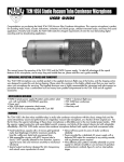
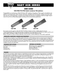
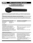
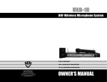
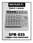
SRA SERIES
Professional Power Amplifiers
Contents
Features ............................................... 1
Warning ................................................ 2
Controls and Connections ................ 3, 4
Typical Set-up ....................................... 5
Specifications ........................................ 6
1
INSTRUCTIONS PER TAINING TO A RISK OF FIRE,
ELECTRIC SHOCK, OR INJURY TO PERSONS.
An equilateral triangle enclosing a lightening flash/
arrowhead symbol is intended to alert the user to
the presence of uninsulated “dangerous voltage”
within the product’s enclosure, which may be of
sufficient magnitude to constitute a risk of electric shock.
An equilateral triangle enclosing an exclamation
point is intended to alert the user to the presence
of important operating and service instructions in
the literature enclosed with this unit.
IMPOR TANT SAFETY INSTRUCTIONS
SA VE THESE INSTRUCTIONS
W ARNING – When using electric products, basic precautions should always be followed, including the following:
1. Read all the instructions before using the product.
2. Do not use this product near water (e.g., near a bathtub, washbowl, kitchen sink, in a wet basement, or near a swimming pool, etc.)
3. This product should be used only with a cart or stand that will keep it level and stable and prevent wobbling.
4. This product, in combination with headphones or speakers, may be capable of producing sound levels that could cause
permanent hearing loss. Do not operate for a long period of time at a high volume level or at alevel that is uncomfortable. If you experience any hearing loss or ringing in the ears, you should consult aaudiologist.
5. The product should be located so that its location or position does not interfere with its proper ventilation.
6. The product should be located away from heat sources such as radiators, heat vents, or other devices ( including
amplifiers) that produce heat.
7. The product should be connected to a power supply only of the type described in the operating instructions or as marked on
the product. Replace the fuse only with one of the specified type and size and with the correct rating.
8. The power-supply cord should : (1) be undamaged, (2) never share an outlet or extension cord with other devices so that
the outlet’s or extension cord’s power rating is exceeded, or (3) be left plugged into the outlet when left unused for a long
period of time.
9. Care should be taken so that objects do not fall into and liquids are not spilled through the enclosure ‘s openings.
10. The product should be serviced by qualified service personnel when:
A. The power-supply cord or the plug has been damaged; or
B. Objects have fallen, or liquid has been spilled onto the product; or
C. The product has been exposed to rain; or
D. The product does not appear to operate normally or exhibits a marked change in performance; or
E. The product has been dropped, or the enclosure damaged.
11. Do not attempt to service the product beyond that described in the user-maintenance instructions. All other servicing
should be referred to qualified service personnel.
This product may be equipped with a polarized line plug (one blade wider than the other). This is a safety feature.
If you are unable to insert the plug into the outlet, contact an electrician to replace your obsolete outlet. Do not defeat
the safety purpose of the plug.
(For use in the U.S.A.)
IMPOR TANT : THE WIRES IN THIS MAINS LEAD ARE COLORED IN ACCORDANCE WITH THE FOLLOWING CODE.
BLUE : NEUTRAL
BROWN : LIVE
As the colors of the wires in the mains lead of this apparatus may not correspond with the colored markings identifying
the terminals in your plug proceed as follows: The wire which is colored BLUE must be connected to the terminal which
is marked with the letter N or colored BLACK. The wire which is colored BROWN must be connected to the terminal which
is marked with the letter L or colored RED. Under no circumstances must either of the above wires be connected to the
earth terminal of a three-pin plug.
(For use in Europe)
2
Controls
&
Connections:
14
REAR PANEL
14
15
Speaker
Output
Channel 2
Speaker
Output
+
Channel 1
+
Voltage
120V
Mode
240V
Impedance
Ground
Unbalanced
Input
9
2
Balanced
Input
11
12
4
Impedance
-
8
13
-
2
4
8
13
16
Stereo
Bridged
Unbalanced
Input
Balanced
Input
11 10
12
FRONT PANEL
VOLUME.R
VOLUME.L
20
18
16
14
20
12
24
8
L/MONITOR
6
40
4
50
POWER
&
PROTECT
3
60
18
16
2
H.P.F
H.P.F
PEAK
SG.IN
ON
OFF
ON
OFF
POWER
&
PROTECT
ON
OFF
1
12
10
28
8
60
2
34
PEAK
6
40
4
50
3
1
70
0
-dB
1.
14
24
10
28
34
0
-dB
POWER SWITCH:
To turn the unit ON or OFF, press the upper or lower portion of this button. The LED in the switch will light to indicate
that the unit is ON.
CAUTION: Always turn on your power amplifier last, after all your other connected equipment, and always turn off
your power amplifier before your other connected equipment.
2.
MONITOR JACK:
This 1/4” TRS phone jack allows monitoring of the amplifier with stereo headphones.
3.
SPEAKER ON/OFF SWITCHES:
Turn off the main speakers with this switch for private amplifier output monitoring via the MONITOR JACK.
4.
SUB FILTER ON/OFF SWITCHES:
Use this to eliminate the lowest frequencies from your output signal. This steep low-cut filter will help eliminate
common low frequency problems in your signal such as hum and other signal components that can cause speaker
rumble and/or resonance, without noticeably degrading the integrity of the audio.
5.
PEAK LED INDICATORS:
These LEDs illuminate if any section of the power amplifier’s output is within 3dB of clipping. Occasional blinking of
these LEDs is acceptable, but if they remain on more than intermittently you should turn down either the amplifier’s
level control or reduce the output level of the preceding component to avoid audible distortion.
6.
PROTECTION LED INDICATORS:
These LEDs illuminate when the unit is overheated, or when a shorted load or DC is detected in the amplifier output.
When either of these LEDs is lit up, turn OFF the power and check the output’s connection to verify that it is correct,
then turn ON the power again. The amplifier will reset itself when the problem is corrected.
7.
SIGNAL LEDS:
These LEDs illuminate to confirm the presence of an input audio signal at that channel of the amplifier.
8.
LEVEL CONTROLS:
These control the level of signal coming into each channel. Turn these controls counterclockwise if the peak LEDs
illuminate steadily (indicating too strong an input signal).
9.
GROUND:
For safety, and to help eliminate ground loop hum, connect a properly grounded ground wire here.
3
Controls
&
Connections:
10. STEREO/BRIDGE SELECT SWITCH:
This is used to select "STEREO" or "BRIDGE" mode operation. Before switching, verify that the output’s connection
is correct. The connections should be as follows:
STEREO MODE:
a. Mixer or EQ right channel line output to amplifier right channel line input
b. Mixer or EQ left channel line output to amplifier left channel line input
c. Amplifier right channel speaker output (+) to speaker (+) and right channel speaker (-) to speaker (-)
d. Amplifier left channel speaker output (+) to speaker (+) and left channel speaker (-) to speaker (-)
MONO BRIDGED MODE:
a. Mixer or EQ right channel line output to amplifier right channel line input
b. Amplifier right channel speaker output (+) to speaker (+) and left channel speaker output (+) to speaker (-)
c. (Optional) Connect a second speaker as above: amplifier right channel speaker output (+) to speaker (+) and
left channel speaker output (+) to speaker (-)
11. UNBALANCED INPUT JACKS (RCA):
These jacks are compatible with unbalanced input from components with RCA output jacks.
12. BALANCED INPUT CONNECTORS (1/4” TRS & XLR):
These 1/4” TRS (Tip Ring Sleeve) phone jacks and XLR jacks are compatible with balanced input and are wired as
Tip/Pin 3 = Cold (+), Ring/Pin 2 = Hot (-), and Sleeve/Pin 1 = Ground.
13. IMPEDANCE SWITCHES:
Use these switches to select the proper speaker load impedance for each channel: 2, 4, or 8 Ohms
14. OUTPUT CONNECTORS (1/4” Phone Jack & Binding Posts):
The speakers for each channel output can be connected either to the 1/4” phone jack or to the screw terminal binding
posts (banana jacks).
15. AC VOLTAGE SELECTOR SWITCH:
Before plugging in the power cord, check to see that the unit is set for the proper voltage for you area: ~115V (60Hz)
or ~230V (50Hz).
16. FUSE HOLDER & POWER CORD CONNECTOR:
This fuse holder contains an AC primary fuse. When this fuse blows, replace it with the same type fuse, size and
power rating (see SPECIFICATIONS). If it continuously blows, stop replacing the fuse and refer servicing to qualified
personnel.
CAUTION: After checking the AC supply voltage, be sure that the correct fuse is in the fuse holder.
The cord connector is used to connect the AC power source to your power amplifier.
CAUTION: DO NOT REMOVE THE CENTER GROUNDING PIN.
4
Typical
STEREO
Set-up
SPEAKER
SPEAKER
-
+
STEREO
+
Speaker
Output
Speaker
Output
Channel 2
+
Channel 1
+
Voltage
Mode
240V
120V
Impedance
Ground
Unbalanced
Input
-
Impedance
-
Balanced
Input
-
2
4
8
Balanced
Input
Unbalanced
Input
Stereo
Bridged
SET TO STEREO
MIXER
OR
EQUALIZER
L
R
LINE OUT
SPEAKER 2
SPEAKER 1
MONO
BRIDGED
MONO
BRIDGED
-
+
2 SPEAKERS
-
+
Speaker
Output
Speaker
Output
Channel 2
+
Channel 1
+
Voltage
Mode
240V
120V
Impedance
Ground
Unbalanced
Input
Impedance
-
Balanced
Input
-
2
4
8
Balanced
Input
Unbalanced
Input
SPEAKER
SET TO MONO
-
+
1 SPEAKER
Speaker
Output
Speaker
Output
+
Channel 2
+
Voltage
120V
Channel 1
Mode
240V
Impedance
Ground
Unbalanced
Input
Stereo
Bridged
Impedance
2
Balanced
Input
4
8
Balanced
Input
Unbalanced
Input
Stereo
Bridged
SET TO MONO
MIXER
OR
EQUALIZER
R
LINE OUT
5
L
Specifications
INPUTS:
ONE XLR JACK & ONE 1/4” TRS PHONE JACK FOR EACH CHANNEL
47 KOHM BALANCED & 40 KOHMS UNBALANCED
OUTPUTS:
ONE 1/4” PHONE JACK & ONE PAIR BINDING POST SCREW TERMINALS FOR EACH
CHANNEL
SRA 2150: RMS 150W X 2 @ 4 OHMS / BRIDGED RMS 250W @ 8 OHMS
SRA 2250: RMS 250W X 2 @ 4 OHMS / BRIDGED RMS 350W @ 8 OHMS
LOWEST OUTPUT LOAD IMPEDANCES:
STEREO: 2 OHMS, BRIDGED: 4 OHMS
FREQUENCY RESPONSE:
5Hz~40KHz, +/- 0.5dB
SIGNAL-TO-NOISE RATIO (IEC-A):
> 94dB
T.H.D.:
< 0.05%
INDICATORS:
POWER/ON, SIGNAL, PEAK, PROTECT
COOLING:
CONVECTION (NO FAN)
FUSE REQUIREMENTS (115V/230V):
SRA 2150:
5X20mm GLASS TUBE, 5A SLOW BLOW
SRA 2250:
5X20mm GLASS TUBE, 5A SLOW BLOW
DIMENSIONS:
SRA 2150/2250:
WEIGHT:
SRA 2150:
SRA 2250:
19” x 1.75” x 11.8” (481 X 44 X 300mm),
1U RACK HEIGHT
14.3 lbs (6.5 Kg)
16.5 lbs (7.5 Kg)
For improvement purposes, specifications and design subject to change without prior notice
6
SERVICE FOR YOUR NADY AUDIO PRODUCT
(U.S.) Should your NADY AUDIO Product require service,
please contact the Nady Service Department via phone
at (510) 652-2411 or E-mail at [email protected].
(INTERNATIONAL) For service, please contact the
NADY AUDIO distributor in your country through the
dealer from whom you purchased this product.
DO NOT ATTEMPT TO SERVICE
THIS UNIT YOURSELF AS IT CAN
BE DANGEROUS AND ALSO WILL
VOID THE WARRANTY.