1
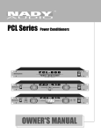
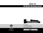
FS-4N
FEEDBACK SUPPRESSOR
Congratulations!
You have purchased one of the finest professional feedback suppressors on the market today. This unit was
developed using the expertise of professional sound
engineers and working musicians. You will find your new
NADY AUDIO FS-4N has superior performance and
greater flexibility than any other feedback suppressor in
its price range. Please read this manual carefully to get
the most out of your new unit. Thanks for selecting NADY
AUDIO as your choice in feedback suppressors.
Date of Purchase
Dealer’s Name
City
State
Zip
Model#
Serial #
Features
Offering the ultimate ease of operation, the FS-4N is the straightforward solution to feedback and hum problems in
live sound applications.
• Single rack space (1U) rugged metal housing for reliability
• Four extremely narrow (1/60 octave) notch filters, each independently adjustable from 60 to 6,000 Hz,
allow quick elimination of unwanted problem frequencies without affecting the integrity of the overall sound.
• A control for adjusting the notch depth on each filter enables precise attenuation (up to -20 dB) at each
selected frequency.
• A push button bypass switches all four notches in and out simultaneously for fast monitoring of results
during use.
• An in-line 8-band audio spectrum analyzer LED display enables quick identification of the frequency
range of any problem frequency, facilitating immediate reaction and suppression by the operator.
• 1/4" TRS balanced jacks for both SIGNAL IN and OUT
• Internal shielded power supply with external fuse and ~115V (60Hz) / ~230V (50Hz) AC select switch
• IEC power cord socket for AC operation and screw terminals for optional +24 VDC input powering
2
CONTENTS
FEATURES ........................................................................................................................................... 2
WARNING .......................................................................................................................................... 4
CONTROLS AND CONNECTIONS ...................................................................................................... 5
TYPICAL SETUP ................................................................................................................................... 7
SPECIFICATIONS ................................................................................................................................. 8
ATTENTION:
An equilateral triangle enclosing a lightening flash/arrowhead symbol is
intended to alert the user to the presence of uninsulated “dangerous
voltage” within the product’s enclosure which may be of sufficient
magnitude to constitute a risk of electric shock.
RISQUE DE CHOC ELECTRIQUE NE PAS OUVRIR
An equilateral triangle enclosing an exclamation point is intended to alert
the user to the presence of important operating and service instructions in
the literature enclosed with this unit.
IMPORTANT SAFETY INSTRUCTIONS
WARNING — When using electric products, basic precautions should always be followed, including the following:
1.
2.
3.
4.
5.
6.
7.
8.
9.
10.
11.
4
Read all the instructions before using the product.
Do not use this product near water (e.g., near a bathtub, washbowl, kitchen sink, in a wet basement, or
near a swimming pool, etc.).
This product should be used only with a cart or stand that will keep it level and stable and prevent
wobbling.
This product, in combination with headphones or speakers, may be capable of producing sound levels
that could cause permanent hearing loss. Do not operate for a long period of time at a high volume level
or at a level that is uncomfortable. If you experience any hearing loss or ringing in the ears, you should
consult aaudiologist.
The product should be located so that its location or position does not interfere with its proper ventilation.
The product should be located away from heat sources such as radiators, heat vents, or other devices
( including amplifiers) that produce heat.
The product should be connected to a power supply only of the type described in the operating
instructions or as marked on the product. Replace the fuse only with one of the specified type and size
and with the correct rating.
The power supply cord should : (1) be undamaged, (2) never share an outlet or extension cord with other
devices so that the outlet’s or extension cord’s power rating is exceeded, and (3) be left plugged into the
outlet when left unused for a long period of time.
Care should be taken so that objects do not fall into, and liquids are not spilled through, the enclosure's
openings.
The product should be serviced by qualified service personnel when:
A. The power supply cord or the plug has been damaged; or
B. Objects have fallen into, or liquid has been spilled onto the product; or
C. The product has been exposed to rain; or
D. The product does not appear to operate normally or exhibits a marked change in performance; or
E. The product has been dropped, or the enclosure damaged.
Do not attempt to service the product beyond what is described in the user-maintenance instructions. All
other servicing should be referred to qualified service personnel.
CONTROLS AND CONNECTIONS
FRONT PANEL
5
4
3
2
1
1. POWER SWITCH
To turn the unit ON or OFF, press the upper or lower portion of this button.
2. POWER LED INDICATOR
This LED illuminates when the power is turned "ON".
3. AUDIO SPECTRUM ANALYZER DISPLAY
This in-line 8-band audio spectrum analyzer enables quick identification of the frequency range of any
problem frequency and allows monitoring of the amount of reduction selected in any of the notches.
The display monitors both the input and output levels as selected by the Bypass switch (5). It monitors the output
when the switch is IN (down), and the input when the switch is OUT (up) for bypass mode. The audio spectrum
display has a range of 25Hz to 16 KHz in 8 frequency bands, with 6 LEDs in each tree indicating levels
from +3 to –20dB.
4. NOTCH FILTERS
Use these notch filters to control up to four different feedback (howling or screeching resonances) frequencies
independently.
a. FREQUENCY SELECT CONTROL
Adjust the desired suppression frequency for each notch independently with this control. The filters are
extremely narrow (1/60 octave) so take care in properly tuning out the desired feedback.
b. SCALE FREQUENCY MULTIPLIER SWITCH
Use this switch to select either X1 (up) or X10 (down) multiplier of the frequency scale on the Frequency
Select Control as needed to "tune in" on the desired suppression frequency.
c. NOTCH DEPTH CONTROL
Use this control for precise adjustment of the amount of attenuation (up to -20dB) necessary to suppress the
selected feedback frequency. For the least effect on your overall sound, adjust the attenuation to just below
the amount needed to suppress feedback.
5. BYPASS IN/OUT SWITCH
Use this switch to select all 4 notches simultaneously either IN (down) or bypassed OUT (up) for fast monitoring
of results during use.
5
REAR PANEL
10
9
11
8
7
6
6. BALANCED SIGNAL INPUT JACK (1/4" TRS)
This 1/4" TRS (Tip/Ring/Sleeve) phone jack is wired for balanced input signals (0.775V=0dBm, 15K Ohms)
and signal polarity is Tip = Cold (+), Ring = Hot (-), and Sleeve = Ground.
7. BALANCED SIGNAL OUTPUT JACK (1/4" TRS)
This 1/4" TRS jack provides a balanced signal output (600 Ohms) and is wired with the same signal polarity
as the Input Jack above.
8. 24 VDC TERMINAL
Use this screw terminal to operate the unit with external 24 VDC powering, either from a power supply or a
battery. Observe the correct polarity (+ and -) when making connections as marked on the terminal. The power
requirement is 250 mA.
9. AC FUSE HOLDERS
This fuse holder contains an AC primary fuse. When this fuse blows, replace it with the same type fuse, size
and power rating (120 VAC: 0.315A/250V; 230 VAC: 0.2A/250V). If it continuously blows, stop replacing
the fuse and refer servicing to qualified personnel.
CAUTION: After checking the AC supply voltage, be sure that the correct fuse is in the fuse holder.
10. POWER CONNECTOR
The IEC cord connector is used to connect the AC power source to your power amplifier.
CAUTION: DO NOT REMOVE THE CENTER GROUNDING PIN.
11. AC VOLTAGE SELECTOR SWITCH
Before plugging in the power cord, check to see that the unit is set for the proper voltage for your area:
~115V (60Hz) or ~230V (50Hz).
6
TYPICAL SETUP
The FS-4N Feedback Suppressor is typically connected between the mixer and other effects or processors and/or the
power amplifier in live sound applications. The entire audio in a given setup should feed through the FS-4N so that
you may control all hum, noises and feedback appearing anywhere in the signal you are amplifying. Since both
monitor (if used) and FOH (Front-of-House) amplification may cause feedback, it may be necessary to suppress
frequencies in each loop. Furthermore, you may also be using a stereo FOH mix. Since the FS-4N is a mono unit,
up to three units may be needed in stereo live sound setups for total control of the monitor and each side of the
stereo FOH amplification.
F.O.H. MIX
STEREO AMP
VOL
VOL
FRONT-OF-HOUSE
STEREO AMP
F.O.H. SPEAKERS
MONITOR MIX
MONO AMP
VOL
MONITOR
MONO AMP
STAGE MONITOR
SPEAKERS
NOTE: Insert any processors, EQ’s, etc. between the mixer and the FS-4N. The Feedback Suppressor should be the
last processor in line before connecting the audio to the amplifier.
7
SPECIFICATIONS
INPUT CONNECTOR:
INPUT SENSITIVITY:
INPUT IMPEDANCE:
OUTPUT CONNECTOR:
OUTPUT LEVEL:
OUTPUT IMPEDANCE:
FREQUENCY RESPONSE:
SIGNAL-TO-NOISE RATIO:
T.H.D.:
NOTCH FILTER FREQUENCY RANGE:
NOTCH DEPTH:
POWER CONSUMPTION:
POWER SOURCE:
FUSE REQUIREMENTS:
DIMENSIONS:
WEIGHT:
One 1/4" TRS phone jack
0.775 (0dBm)
15 K ohm balanced
One 1/4" TRS phone jack
0.775 (0 dBm)
600 OHM BALANCED
20Hz~20KHz, < ±1.0 dB
> 68 dB
< 0.4%
60 HZ ~ 6 KHz, continuously variable
0 ~ -20 dB
5.5 Watts
AC: 120V/230V, 50/60 Hz; DC: 24V
120 VAC: 0.315 A / 250V;
230 VAC: 0.2A / 250V
19" X 1.75" X 8.3"
(483 X 44 X 210mm), 1U rack height
6.6 lbs (3.0 Kg)
Note: For improvement purposes, specifications, design and appearance are subject to change without
prior notice.
8