1
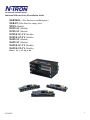
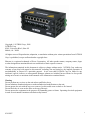
900 Series
Industrial Ethernet
Switch
Installation
& User’s Guide
Industrial Ethernet Switch Installation Guide
900B/900N (3 Slot Enclosure and Backplane)
900B-FP (Filler Panel for empty slots)
908TX (Module)
902FX-SC (Module)
902FX-ST (Module)
902FXE-SC-YY (Module)
902FXE-ST-YY (Module)
904FX-SC (Module)
904FX-ST (Module)
904FXE-SC-YY (Module)
904FXE-ST-YY (Module)
Where: YY = -15, -40, or -80
4/26/2007
2
Copyright, © N-TRON Corp., 2006
N-TRON Corp.
820 S. University Blvd., Suite 4E
Mobile, AL 36609
All rights reserved. Reproduction, adaptation, or translation without prior written permission from N-TRON
Corp. is prohibited, except as allowed under copyright laws.
Ethernet is a registered trademark of Xerox Corporation. All other product names, company names, logos
or other designations mentioned herein are trademarks of their respective owners.
The information contained in this document is subject to change without notice. N-TRON Corp. makes no
warranty of any kind with regard to this material, including, but not limited to, the implied warranties of
merchantability or fitness for a particular purpose. In no event shall N-TRON Corp. be liable for any
incidental, special, indirect or consequential damages whatsoever included but not limited to lost profits
arising out of errors or omissions in this manual or the information contained herein.
Warning
Do not perform any services on the unit unless qualified to do so.
Do not substitute unauthorized parts or make unauthorized modifications to the unit.
Do not operate the unit with the top cover removed, as this could create a shock or fire hazard.
Do not block the air vents on the sides or the top of the unit.
Do not operate the equipment in the presence of flammable gasses or fumes. Operating electrical equipment
in such an environment constitutes a definite safety hazard.
4/26/2007
3
Safety Warnings
ELECTRICAL SAFETY
WARNING: Disconnect the power cable before removing the enclosure top.
WARNING: Do not operate the unit with the top cover removed.
WARNING: Do not work on equipment or cables during periods of lightning activity.
WARNING: Do not perform any services on the unit unless qualified to do so.
WARNING: Do not block the air vents.
WARNING: Observe proper DC Voltage polarity when installing power input cables. Reversing
voltage polarity can cause permanent damage to the unit and void the warranty.
LASER SAFETY (904FXE and 902FXE Only)
WARNING: CLASS 1 Laser Product. Do not stare into the Laser Beam.
4/26/2007
4
900 Series Hazardous Location Installation Requirements
1. WARNING: EXPLOSION HAZARD. DO NOT DISCONNECT UNIT WHILE CIRCUIT IS LIVE,
UNLESS KNOWN TO BE NON-HAZARDOUS.
2. AVERTISEMENT: RISQUE D’EXPLOSION. NEPAS DE’BRANCHER TANT QUE LE CIRCUIT
EST SOUS TENSION, A’MOINS QU’IL S’ A GISSE D’UN EMPLACEMENT NON DANGEREUX.
3. WARNING: Install only in accordance with Local & National Codes of Authorities Having Jurisdiction.
4. Power must be supplied by an isolating source, and a 3.3A max rated UL recognized fuse must be
installed immediately before the unit.
5. Class I, Div 2 installations require that all devices connected to this product must be UL listed for the area in
which it is installed.
6. Only UL listed wiring with temperature ratings greater than 90OC permitted for Class I, Div 2 installations
operating at temperatures up to 70OC ambient.
7. Limited Operating Voltage: 12-30V for Class I, Div 2 installations.
4/26/2007
5
900 Series Industrial Ethernet Switches
The 900 Series Modular Industrial Ethernet Switches support high speed layer 2 switching between ports.
The 900B and 900N enclosures contain a three slot backplane that supports up to three modules. The
908TX, 902FX and 904FX modules are the available modules. The N-TRON Corp. 900B is housed in a
ruggedized steel enclosure, and can withstand industrial temperatures, as well as extreme shock & vibration.
The 908TX is an 8 port module that is capable of auto negotiating 10/100 Mb and half/full duplex
communications. The N-TRON 908TX also supports MDIX auto sensing (for auto connector of straight
through or crossover cables) and provides 8 Category 5 compliant 10/100-BaseT connections for high
performance network design, and hub/repeater upgrades.
The 902FX is a two port 100Mb module that supports multimode fiber. ST and SC connectors are
available.
The 902FXE is a single mode (laser) version of the 902FX, and can support distances of up to 80km.
The 904FX and 904FXE are four port versions of the 902FX and 902FXE respectively.
Key Features
•
Full IEEE 802.3 & 100BASE-FX Compliance
•
Extended Environmental Specifications
•
Support for Full/Half Duplex Operation
•
LED Link/Activity Status Indication
•
Auto Sensing Speed and Flow Control
•
Auto MDIX (908TX only)
•
Up to 4.8 Gb/s Maximum Throughput
•
Industry Standard DIN-Rail Enclosure
4/26/2007
6
PACKAGE CONTENTS
Please make sure the Ethernet Switch package contains the following items:
1. 900 Series Ethernet Switch
2. Installed Modules
3. This Installation Guide
Contact your carrier if any items are damaged.
INSTALLATION
Read the following warning before beginning the installation:
WARNING
The 902FXE and 904FXE unit contain a class 1 laser. Do not stare into the laser beam (fiber optic
connector) when installing or operating the product.
Never install or work on electrical equipment or cabling during periods of lightning activity.
Disconnect the power cable before removing the enclosure top.
Do not operate the unit with the top cover removed
UNPACKING
Remove all the equipment from the packaging, and store the packaging in a safe place.
File any damage claims with the carrier.
4/26/2007
7
902FX/FXE & 904FX /FXE HALF DUPLEX SETUP
All 900 series fiber modules are factory configured for full duplex operation. The setting is controlled
by jumper JP1 on the backplane.
Note: Most 100Mbit fiber systems will be compatible with this Full Duplex setting. If Half Duplex
operation is desired, then follow these steps using proper wrist strap grounding techniques:
1.
2.
3.
4.
5.
6.
Remove the power & power plugs from the unit.
Loosen all thumbscrews & remove all modules.
Remove the six screws holding the backplane
Remove the backplane.
Move the jumper JP1 from position 1-2 to 3-4
Re-install the backplane & modules & power plugs.
JP1
902/904 Note:
Rev. C & D boards are hard wired for Port1 = HDPLX,
Rev. B & E boards are hard wired for Port1 = FDPLX.
4/26/2007
8
DIN-Rail Mounting
Install the unit in a standard DIN-Rail. Recess the unit to allow at least 5” of horizontal clearance for
fiber optic cable bend radius (2” for TX models). Note: This unit may be mounted horizontally or
vertically.
To install the unit to 35mm industrial DIN-Rail - Place the top edge of the included mounting bracket on
the back of the unit against the top flange of the DIN-Rail at a 15° angle. Rotate the bottom of the unit to
the back (away from you) until it snaps into place.
To remove the unit from the 35 mm industrial DIN-Rails - Apply downward force to the unit until it
disengages from the bottom of the unit from the DIN-Rail. Then, rotate the unit approximately 15°
upward and towards you to completely remove it.
Optional Mounting
The 900 Series Ethernet switches were designed to be mounted on industry standard 35mm DIN-Rail.
However, DIN-Rail mounting may not be suitable for all applications. We offer two alternative
mounting solutions.
Our 900 Panel Mount Assembly (P/N: 900-PM) may be used to securely mount the 900 Series products
to a panel or other flat surface.
Our Rack Mount Assembly (P/N: 900-RM) may be used to mount our products to standard 19" racks.
4/26/2007
9
MODULE CONFIGURATION SETTINGS
In order for the 900 Series modules to communicate properly the chassis must be populated with modules from the top
slot down as shown below. In addition, JP1 and JP2 jumpers (located on top side of all modules) must be configured as
indicated below.
Note: The power source must be disconnected from the 900B chassis prior to removing and inserting modules. This
unit is not hot swappable.
One Slot Configuration - When installing a single 902FX, 904FX, or 908TX module in
the top slot of the 900B chassis… Configure the module as follows:
JP1: pins 1 & 2 shorted
JP2: pins 1 & 2 shorted
Two Slot Configuration - When installing two 902FX, 904FX, and/or 908TX modules
in the top two slots of the 900B chassis… Configure both modules as follows:
JP1: pins 1 & 2 shorted
JP2: pins 3 & 4 shorted
Three Slot Configuration - When installing three 902FX, 904FX, and/or 908TX
modules in all three slots of the 900B chassis… Configure all modules as follows:
JP1: pins 3 & 4 shorted
JP2: pins 3 & 4 shorted
908TX Module - At power cycle, all LED’s flash on for approximately two seconds, and
then return to proper state.
Green LED will light when Power is connected.
902FX & 904FX Modules - At power cycle, only the LED’s on the first port flash on to
indicate the reset condition, and then return to their proper state. All other reports remain
off during reset. This is normal behavior.
Green LED will light when Power is
connected.
4/26/2007
10
908TX Module
From Left to Right:
RJ45 Ports
Upper Left LED
Upper Right LED
Ports 1-8 Auto sensing 10/100BaseT Ports
Port Link Status
Port Activity Status
Green LED lights when Power is connected
Note: At power cycle, all LED’s flash on for approximately two seconds, and then return to proper
state.
LED’s: The table below describes the operating modes:
LED
Color
GREEN
OFF
LNK
GREEN
OFF
GREEN
ACT
OFF
Description
Power is Applied
Power is OFF
Link between ports
established
No Link between ports
Data is active between
ports
Data is inactive between
ports
908 Module Jumper Settings
JP1
install jumper in location 1-2 when 1 or 2 modules installed
install jumper in location 3-4 when 3 modules installed
JP2
install jumper in location 1-2 when 1 module installed
install jumper in location 3-4 when 2 or 3 modules installed
4/26/2007
11
902/904 FX & FXE Module
From Left to Right:
TX
RX
LNK
ACT
Fiber Optic Transmit Port
Fiber Optic Receive Port
Link LED (top LED) for Fiber Optic Port
Activity LED (bottom LED) for Fiber Optic Port
Green LED lights when Power is connected
Note: At power cycle, only the LED’s on the first port flash on to indicate the reset condition, and then
return to their proper state. All other reports remain off during reset. This is normal behavior.
LED’s: The table below describes the operating modes:
LED
LNK
Color
Description
GREEN
Power is Applied
OFF
Power is OFF
GREEN
Link between ports established
OFF
No Link between ports
GREEN
Data is active between ports
OFF
Data is inactive between ports
ACT
902/904 Module Jumpers Settings
JP1
install jumper in location 1-2 when 1 or 2 modules are installed
install jumper in location 3-4 when 3 modules are installed
JP2
install jumper in location 1-2 when 1 module are installed
install jumper in location 3-4 when 2 or 3 modules are installed
4/26/2007
12
APPLYING POWER
1.
2.
3.
4.
Unscrew the flange & Remove the DC Voltage Input Plug(s) from the side headers.
Install the DC Power Cables into the Plug(s) (observing polarity).
Tightening torque for the terminal block power plug is 0.22 Nm/0.162 Pound Foot.
Plug the Voltage Input Plug(s) back into the side header. All 10/100BaseT LED’s will flash ON
Momentarily. For fiber optic ports, only port 1 will flash momentarily.
5. Verify the Power LED stays ON (GREEN).
Note: Only 1 plug must be connected to power for minimal operation. For redundant power operation,
V1 and V2 plugs must be connected to separate DC Voltage sources. Use wire sizes 16-28 guage.
Recommended 24V DC Power Supplies, similar to
120/240VAC:
NTPS-24-3, 24VDC at 3A
4/26/2007
13
N-TRON SWITCH GROUNDING TECHNIQUES
The grounding philosophy of any control system is an integral part of the design. N-Tron switches are designed
to be grounded, but the user has been given the flexibility to float the switch when required. The best noise
immunity and emissions (i.e. CE) are obtained when the N-Tron switch chassis is connected to earth ground via
a drain wire. Some N-Tron switches have metal din-rail brackets that can ground the switch if the din-rail is
grounded. In some cases, N-Tron switches with metal brackets can be supplied with optional plastic brackets if
isolation is required.
Both V- legs of the power input connector are connected to
chassis internally on the PCB. Connecting a drain wire to
earth ground from one of the V- terminal plugs as shown here
will ground the switch and the chassis. The power leads from
the power source should be limited to 3 meters or less in
length.
As an alternate, users can run a drain wire & lug from any of the Din-Rail
screws or empty PEM nuts on the enclosure. When using an unused PEM
nut to connect a ground lug via a machine screw, care should be taken to
limit the penetration of the outer skin by less than 1/4 in. Failure to do so
may cause irreversible damage to the internal components of the switch.
Note: Before applying power to the grounded switch, you must use a volt
meter to verify there is no voltage difference between the power supply’s
negative output terminal and the switch chassis grounding point.
The use of shielded cables between devices is not required for most N-Tron devices (please consult the user
manuals for specific details). If the use of shielded cables is required, it is generally recommended to only
connect the shield at one end to prevent ground loops and interfere with low level signals (i.e. thermocouples,
RTD, etc.). Cat5e cables manufactured to EIA-568A or 568B specifications are required for use with N-Tron
Switches.
In the event all Cat5e patch cable distances are small (i.e. All Ethernet devices are located the same local
cabinet and/or referenced to the same earth ground), it is permissible to use fully shielded cables terminated to
chassis ground at both ends in systems void of low level analog signals.
4/26/2007
14
CONNECTING THE UNIT
For 902 & 904 FX & FXE units, remove the dust cap from the fiber optic connectors and connect the
fiber optic cables. The TX port on the 902 and/or 904 units should be connected to the RX port of the
far end station. The RX port on the 902 and/or 904 units should be connected to the TX port of the far
end station.
For 10/100 Base-TX ports, plug a Category 5 twisted pair cable into the RJ45 connector. Connect the
other end to the far end station. Verify that the LNK LED’s are ON once the connection has been
completed. For Switch to Switch or Switch to Repeater connections, since the 908TX supports the
advanced MDIX function, there is no need to use crossover cables. The 908TX will sense & adapt
accordingly.
TROUBLESHOOTING
1. Make sure the
(Power LED) is ON.
2. Make sure the ! (Error LED) remains OFF 3 seconds after initial power up.
3. Verify that Link LED’s are ON for connected ports.
4. Verify straight through cabling used between stations.
5. Verify cabling (pin-outs & integrity).
6. Verify that cabling is Category 5 (or higher) for 100Mbit Operation.
7. Verify TX is connected to far end RX and vise versa
(902 and 904 FX/FXE only).
SUPPORT
Contact N-TRON Corp. at:
TEL: 251-342-2164
FAX: 251-342-6353
Website: www.n-tron.com
E-Mail: [email protected]
FCC STATEMENT
This product complies with Part 15 of the FCC-A Rules.
Operation is subject to the following conditions:
(1) This device may not cause harmful Interference
(2) This device must accept any interference received, including interference that may cause undesired
operation.
4/26/2007
15
Key Specifications
Physical
Height:
3.2" (8.13 cm)
Width:
7.1" (18.03 cm)
Depth:
4.1" (10.41 cm)
Weight:
~3.0 lbs (2.3 kg)
(Note: This unit may be mounted horizontally or vertically)
Electrical
Input Voltage:
Input Current:
Inrush Current:
Inrush Current:
10-30 VDC (Regulated)
390 mA @ 24VDC (Steady State)
13.7 Amp / 1.9 ms @ 24VDC with (3) 908TX modules
13.9 Amp / 1.9 ms @ 24VDC with (3) 904FX modules
Environmental
Operating Temperature:
Storage Temperature:
Operating Humidity:
(Non-Condensing)
Operating Altitude:
-20oC to 70oC (-4°F to 158oF)
-20oC to 85oC (0°F to 185oF)
10% to 90%
0 to 10,000 ft.
Shock and Vibration (Bulkhead Mounting)
Shock:
200g @ 10ms
Vibration:
1g, 10-500Hz, 3 axis
Seismic:
20g, 5-200Hz, 15s
Reliability
MTBF:
Network Media
10BaseT:
100BaseT:
100BaseFX:
>1M Hours (measured)
> Cat-3 Cable
> Cat-5 Cable
Multimode: 50-62.5/125µm Fiber
Singlemode: 7-9/125µm Fiber
Fiber Transceiver Characteristics
Fiber Length:
2km*
15km**
40km**
80km**
TX Power Min/Max
-19dBm/-14dBm
-15dBm/-7dBm
5dBm/0dBm
-5dBm/0dBm
RX Sensitivity Max: -32dBm
-34dBm
-34dBm
-34dBm
Wavelength:
1310nm
*=Multimode ** =Singlemode
1310nm
1310nm
1550nm
Recommended Wiring Clearance:
Front:
2" (5.08 cm)
Side:
1" (2.54 cm)
4/26/2007
16
Regulatory Approvals:
Safety: UL 1604 (US and Canada) Hazardous Locations, Class I, Zone 2, Group IIC, T4A
EMI: EN50081-1:1992, EN55022 – Class A
FCC Part 15 Class A
EMS: EN55024:1998
EN61000-4-2:1995
EN61000-4-3:1995
EN61000-4-4:1995
EN61000-4-5:1995
EN61000-4-6:1995
Note: Shielded cables must be used to meet emission standards
.
Ordering Information
PN
Description
900B
900-RM
900-PM
908TX
902FX-XX
902FXE-XX-YY
904FX-XX
904FXE-XX-YY
Industrial Ethernet switch chassis with 3 slots for optional expansion modules
19" Rack Mount Kit
Panel Mount Kit
Eight ports 10/100BaseTX (RJ45)
Two ports 100BaseFX multimode fiber
Two ports 100BaseFX singlemode fiber
Four ports 100BaseFX multimode fiber
Four ports 100BaseFX singlemode fiber
Where "XX" is:
ST for ST style fiber connector
SC for SC style fiber connector
Where "YY" is:
15 for 15km max. fiber segment length
40 for 40km max. fiber segment length
80 for 80km max. fiber segment length
Warranty
One Year Parts & Labor
Contact/Support Information
N-TRON Corp.
820 S. University Blvd., Suite 4E
Mobile, AL 36609
TEL (251) 342-2164
FAX (251) 342-6353
Website: www.n-tron.com
E-Mail: [email protected]
4/26/2007
17
N-TRON Limited Warranty
N-TRON, Corp. warrants to the end user that this hardware product will be free from defects in workmanship and materials, under normal use
and service, for the applicable warranty period from the date of purchase from N-TRON or its authorized reseller. If a product does not operate
as warranted during the applicable warranty period, N-TRON shall, at its option and expense, repair the defective product or part, deliver to
customer an equivalent product or part to replace the defective item, or refund to customer the purchase price paid for the defective product. All
products that are replaced will become the property of N-TRON. Replacement products may be new or reconditioned. Any replaced or repaired
product or part has a ninety (90) day warranty or the remainder of the initial warranty period, whichever is longer. N-TRON shall not be
responsible for any custom software or firmware, configuration information, or memory data of customer contained in, stored on, or integrated
with any products returned to N-TRON pursuant to any warranty.
OBTAINING WARRANTY SERVICE: Customer must contact N-TRON within the applicable warranty period to obtain warranty service
authorization. Dated proof of purchase from N-TRON or its authorized reseller may be required. Products returned to N-TRON must be preauthorized by N-TRON with a Return Material Authorization (RMA) number marked on the outside of the package, and sent prepaid and
packaged appropriately for safe shipment. Responsibility for loss or damage does not transfer to N-TRON until the returned item is received by
N-TRON. The repaired or replaced item will be shipped to the customer, at N-TRON’s expense, not later than thirty (30) days after N-TRON
receives the product. N-TRON shall not be responsible for any software, firmware, information, or memory data of customer contained in,
stored on, or integrated with any products returned to N-TRON for repair, whether under warranty or not.
ADVANCE REPLACEMENT OPTION: Upon registration, this product qualifies for advance replacement. A replacement product will be
shipped within three (3) days after verification by N-TRON that the product is considered defective. The shipment of advance replacement
products is subject to local legal requirements and may not be available in all locations. When an advance replacement is provided and
customer fails to return the original product to N-TRON within fifteen (15) days after shipment of the replacement, N-TRON will charge
customer for the replacement product, at list price.
WARRANTIES EXCLUSIVE: IF AN N-TRON PRODUCT DOES NOT OPERATE AS WARRANTED ABOVE, CUSTOMER'S SOLE
REMEDY FOR BREACH OF THAT WARRANTY SHALL BE REPAIR, REPLACEMENT, OR REFUND OF THE PURCHASE PRICE
PAID, AT N-TRON'S OPTION. TO THE FULL EXTENT ALLOWED BY LAW, THE FOREGOING WARRANTIES AND REMEDIES
ARE EXCLUSIVE AND ARE IN LIEU OF ALL OTHER WARRANTIES, TERMS, OR CONDITIONS, EXPRESS OR IMPLIED, EITHER
IN FACT OR BY OPERATION OF LAW, STATUTORY OR OTHERWISE, INCLUDING WARRANTIES, TERMS, OR CONDITIONS OF
MERCHANTABILITY, FITNESS FOR A PARTICULAR PURPOSE, SATISFACTORY QUALITY, CORRESPONDENCE WITH
DESCRIPTION, AND NON-INFRINGEMENT, ALL OF WHICH ARE EXPRESSLY DISCLAIMED. N-TRON NEITHER ASSUMES NOR
AUTHORIZES ANY OTHER PERSON TO ASSUME FOR IT ANY OTHER LIABILITY IN CONNECTION WITH THE SALE,
INSTALLATION, MAINTENANCE OR USE OF ITS PRODUCTS. N-TRON SHALL NOT BE LIABLE UNDER THIS WARRANTY IF
ITS TESTING AND EXAMINATION DISCLOSE THAT THE ALLEGED DEFECT OR MALFUNCTION IN THE PRODUCT DOES NOT
EXIST OR WAS CAUSED BY CUSTOMER'S OR ANY THIRD PERSON'S MISUSE, NEGLECT, IMPROPER INSTALLATION OR
TESTING, UNAUTHORIZED ATTEMPTS TO OPEN, REPAIR OR MODIFY THE PRODUCT, OR ANY OTHER CAUSE BEYOND THE
RANGE OF THE INTENDED USE, OR BY ACCIDENT, FIRE, LIGHTNING, POWER CUTS OR OUTAGES, OTHER HAZARDS, OR
ACTS OF GOD.
LIMITATION OF LIABILITY: TO THE FULL EXTENT ALLOWED BY LAW, N-TRON ALSO EXCLUDES FOR ITSELF AND ITS
SUPPLIERS ANY LIABILITY, WHETHER BASED IN CONTRACT OR TORT (INCLUDING NEGLIGENCE), FOR INCIDENTAL,
CONSEQUENTIAL, INDIRECT, SPECIAL, OR PUNITIVE DAMAGES OF ANY KIND, OR FOR LOSS OF REVENUE OR PROFITS,
LOSS OF BUSINESS, LOSS OF INFORMATION OR DATA, OR OTHER FINANCIAL LOSS ARISING OUT OF OR IN CONNECTION
WITH THE SALE, INSTALLATION, MAINTENANCE, USE, PERFORMANCE, FAILURE, OR INTERRUPTION OF ITS PRODUCTS,
EVEN IF N-TRON OR ITS AUTHORIZED RESELLER HAS BEEN ADVISED OF THE POSSIBILITY OF SUCH DAMAGES, AND
LIMITS ITS LIABILITY TO REPAIR, REPLACEMENT, OR REFUND OF THE PURCHASE PRICE PAID, AT N-TRON'S OPTION. THIS
DISCLAIMER OF LIABILITY FOR DAMAGES WILL NOT BE AFFECTED IF ANY REMEDY PROVIDED HEREIN SHALL FAIL OF
ITS ESSENTIAL PURPOSE.
DISCLAIMER: Some countries, states, or provinces do not allow the exclusion or limitation of implied warranties or the limitation of incidental
or consequential damages for certain products supplied to consumers, or the limitation of liability for personal injury, so the above limitations
and exclusions may be limited in their application to you. When the implied warranties are not allowed to be excluded in their entirety, they will
be limited to the duration of the applicable written warranty. This warranty gives you specific legal rights which may vary depending on local
law.
GOVERNING LAW: This Limited Warranty shall be governed by the laws of the State of Alabama, U.S.A.
4/26/2007
18